EP2798143B1 - Connector device for use in wireline intervention operations - Google Patents
Connector device for use in wireline intervention operations Download PDFInfo
- Publication number
- EP2798143B1 EP2798143B1 EP12821176.0A EP12821176A EP2798143B1 EP 2798143 B1 EP2798143 B1 EP 2798143B1 EP 12821176 A EP12821176 A EP 12821176A EP 2798143 B1 EP2798143 B1 EP 2798143B1
- Authority
- EP
- European Patent Office
- Prior art keywords
- piston sleeve
- collet
- housing
- wireline
- restrictor
- Prior art date
- Legal status (The legal status is an assumption and is not a legal conclusion. Google has not performed a legal analysis and makes no representation as to the accuracy of the status listed.)
- Active
Links
Images


Classifications
-
- E—FIXED CONSTRUCTIONS
- E21—EARTH OR ROCK DRILLING; MINING
- E21B—EARTH OR ROCK DRILLING; OBTAINING OIL, GAS, WATER, SOLUBLE OR MELTABLE MATERIALS OR A SLURRY OF MINERALS FROM WELLS
- E21B17/00—Drilling rods or pipes; Flexible drill strings; Kellies; Drill collars; Sucker rods; Cables; Casings; Tubings
- E21B17/02—Couplings; joints
- E21B17/04—Couplings; joints between rod or the like and bit or between rod and rod or the like
-
- E—FIXED CONSTRUCTIONS
- E21—EARTH OR ROCK DRILLING; MINING
- E21B—EARTH OR ROCK DRILLING; OBTAINING OIL, GAS, WATER, SOLUBLE OR MELTABLE MATERIALS OR A SLURRY OF MINERALS FROM WELLS
- E21B17/00—Drilling rods or pipes; Flexible drill strings; Kellies; Drill collars; Sucker rods; Cables; Casings; Tubings
- E21B17/02—Couplings; joints
- E21B17/04—Couplings; joints between rod or the like and bit or between rod and rod or the like
- E21B17/046—Couplings; joints between rod or the like and bit or between rod and rod or the like with ribs, pins, or jaws, and complementary grooves or the like, e.g. bayonet catches
- E21B17/0465—Couplings; joints between rod or the like and bit or between rod and rod or the like with ribs, pins, or jaws, and complementary grooves or the like, e.g. bayonet catches characterised by radially inserted locking elements
-
- E—FIXED CONSTRUCTIONS
- E21—EARTH OR ROCK DRILLING; MINING
- E21B—EARTH OR ROCK DRILLING; OBTAINING OIL, GAS, WATER, SOLUBLE OR MELTABLE MATERIALS OR A SLURRY OF MINERALS FROM WELLS
- E21B33/00—Sealing or packing boreholes or wells
- E21B33/02—Surface sealing or packing
- E21B33/03—Well heads; Setting-up thereof
- E21B33/068—Well heads; Setting-up thereof having provision for introducing objects or fluids into, or removing objects from, wells
- E21B33/072—Well heads; Setting-up thereof having provision for introducing objects or fluids into, or removing objects from, wells for cable-operated tools
-
- F—MECHANICAL ENGINEERING; LIGHTING; HEATING; WEAPONS; BLASTING
- F16—ENGINEERING ELEMENTS AND UNITS; GENERAL MEASURES FOR PRODUCING AND MAINTAINING EFFECTIVE FUNCTIONING OF MACHINES OR INSTALLATIONS; THERMAL INSULATION IN GENERAL
- F16L—PIPES; JOINTS OR FITTINGS FOR PIPES; SUPPORTS FOR PIPES, CABLES OR PROTECTIVE TUBING; MEANS FOR THERMAL INSULATION IN GENERAL
- F16L37/00—Couplings of the quick-acting type
- F16L37/08—Couplings of the quick-acting type in which the connection between abutting or axially overlapping ends is maintained by locking members
- F16L37/12—Couplings of the quick-acting type in which the connection between abutting or axially overlapping ends is maintained by locking members using hooks, pawls, or other movable or insertable locking members
- F16L37/121—Couplings of the quick-acting type in which the connection between abutting or axially overlapping ends is maintained by locking members using hooks, pawls, or other movable or insertable locking members using freely rocking hooks
-
- F—MECHANICAL ENGINEERING; LIGHTING; HEATING; WEAPONS; BLASTING
- F16—ENGINEERING ELEMENTS AND UNITS; GENERAL MEASURES FOR PRODUCING AND MAINTAINING EFFECTIVE FUNCTIONING OF MACHINES OR INSTALLATIONS; THERMAL INSULATION IN GENERAL
- F16L—PIPES; JOINTS OR FITTINGS FOR PIPES; SUPPORTS FOR PIPES, CABLES OR PROTECTIVE TUBING; MEANS FOR THERMAL INSULATION IN GENERAL
- F16L37/00—Couplings of the quick-acting type
- F16L37/62—Couplings of the quick-acting type pneumatically or hydraulically actuated
Definitions
- the present invention relates to a connector device for use in wireline intervention operations, used in the field of oil and gas production.
- Collet connectors are used in the oil and gas production industry to connect two pipes or pipelines together. They comprise a generally cylindrical body with a frustum shaped gripping section.
- the gripping section will usually comprise a number of "fingers”, which are splayed outward to form the generally frustum shaped section. This defines a bore or socket at its centre to receive an item to be connected.
- a locking ring or similar device may be selectively moved over these fingers to force them inwardly and thereby clamp over an item to be connected, such as a pipeline.
- Collet connectors may be used in a variety of locations and applications within the oil and gas production industry. For example, they may be used to connect pipelines together and onto wellheads.
- US4693497 shows a known collet connector, which is useful for understanding the invention.
- the second configuration of the restrictor locks the piston sleeve in the second position when the collet fingers are in the clamping position.
- the restrictor includes at least one indicator rod which typically projects from the housing.
- the piston sleeve engages the indictor rod in the second position.
- the restrictor comprises a threaded flange axially movable on a thread relative to the piston sleeve.
- the indicator rod is typically disposed between the flange and the piston sleeve, and the flange can be screwed down the thread to urge the indicator rod against the piston sleeve and lock it in position.
- the housing can be connected to one of the conduits, typically being formed separately and then attached, or optionally can be formed integrally with one of the conduits.
- the housing can be provided on an adapter that is connected to one of the conduits, although it is also envisaged within the scope of the invention that the housing can be formed directly on the conduit.
- the connector may be compatible with an adapter attachable to a suitable item to be connected, e.g. the wireline conduits.
- the collet fingers and adapter may have cooperating profiles to enable an interference fit to be formed.
- the restrictor may be in the form of a movable flange on the adapter. It may be provided by a threaded portion of adapter and a lock ring moveable on said threaded portion.
- the piston sleeve may have a non-linear inner surface. It may be formed from four discontinuous sections. The four sections may be arranged with a narrowest mean diameter section at a first end of said piston, followed by a larger diameter section, followed by a narrower section followed lastly by a greatest mean diameter section.
- the piston sleeve may have a piston flange projecting outwardly from its outer surface.
- the piston flange may be located within a piston recess located on the inner surface of the housing.
- the outer surface of the collet fingers may form a generally frustum shape in the receiving position.
- the outer surface of the collet fingers may form a more cylindrical shape in the clamping position.
- the outer surface may include a recess or lesser diameter around the outer surface.
- the housing may comprise an upper housing section and a lower housing section. Hydraulic bore(s) may be provided in the housing. The hydraulic bores may be used to provide a conduit for pressurised fluid to urge the piston sleeve from its first position to its second position.
- the connector can optionally incorporate a test port, typically accessible from an external wall of the device, and ported to the external wall.
- the test port is in communication with the seal between the first and second conduits, whereby pressure in the test port can be representative of the pressure at the seal, thereby allowing a user to monitor pressure at the port as a measure of the loading, integrity and functionality of the seal.
- the test port allows injection of pressure behind the seal.
- the connector may be adapted to be used in a surface environment, as opposed to a subsea environment.
- compositions, an element or a group of elements are preceded with the transitional phrase "comprising”, it is understood that we also contemplate the same composition, element or group of elements with transitional phrases “consisting essentially of”, “consisting”, “selected from the group of consisting of”, “including”, or “is” preceding the recitation of the composition, element or group of elements and vice versa.
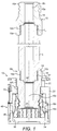
- a collect connector 10 is depicted in section in Fig. 1 .
- the connector 10 is shown attached to a wireline conduit in the form of a lubricator tube L.
- the lubricator tube L is a cylindrical low alloy steel tube which in this case has an internal diameter of 3.563" (90.5mm) and an external diameter of 10" (254.0mm).
- the lubricator tube L has threaded ends L T and L B .
- Two adapters 12,14 are attached to threaded ends L T and L B respectively, although in other examples of the invention, the features of the adapters 12,14 could be integral to the lubricator tube L and the adapters could be omitted.
- the adapters 12,14 comprise substantially cylindrical bodies 16,18 formed from an INCONEL ® alloy. At first ends 16a,18a of the cylindrical bodies 16,18 are provided threaded sockets 16b,18b. As can be seen from Fig. 1 , these threaded sockets 16b,18b receive and allow the connection of the adapters 12,14 to the lubricator tube L. It will be understood that connection is not limited to a lubricator tube L, but that any suitable device may be attached.
- the adapters 12,14 have inner adapter bores 16c,18c provided within them, the inner adapter bores 16c,18c communicating with the threaded sockets 16b,18b. A fluid path right through the adapters 12,14 is therefore provided.
- a metal seal 19 is located adjacent the junction between threaded socket 18b and the inner adapter bore 18c.
- annular toothed profiles 16e,18e are substantially sawtooth-shaped i.e. they are angled recesses within the outer surface of the adapters 16d,18d that have two surfaces at differing angles, one surface being more acute than the other.
- Two annular recesses are provided per profile 16e,18e in the present embodiment, but the number of recesses could be varied in different embodiments without departing from the scope of the invention.
- a further metal seal 21 is located around the inner adapter bore 18c adjacent the second 18d.
- Lower adapter 14 has two external threads located between its first end 18a and second end 18d. Towards the first end 18a (uppermost from the perspective of both Figs) is a lock ring thread 18f. Toward the second end 18d is a main housing thread 18g. Both threads 18f,18g are provided around the outer surface of the lower adapter 14, such that they allow the lower adapter 14 to be a "male” to subsequently described “female” pieces. Both threads 18f,18g are adjacent one another, with the lock ring thread 18f being of greater diameter than the main housing thread 18g, creating a step-wise change in the external diameter of the cylindrical body 18 of the lower adapter 14.
- An upper housing 20 attaches to the lower adapter 14 via the main housing thread 18g of the lower adapter and a threaded orifice 22 of the upper main housing 20.
- the upper housing 20 comprises a flange 24 at the centre of which is defined the threaded orifice 22.
- a cylindrical sidewall 26 extends from the flange 24, the flange 24 and cylindrical sidewall 26 having substantially equivalent outermost diameters.
- An outer chamfer 28 is provided on the outer surface of the upper housing 20 at the junction of flange 24 and sidewall 26.
- a corresponding fillet 30 is provided on the inner surface of the upper housing 20 at the junction of flange 24 and sidewall 26.
- a lower housing thread 32 is provided on the inner surface of the sidewall 26 at the distal end of the upper housing 20 from flange 24.
- a lower housing 34 attaches to the upper housing 20 via the lower housing thread 32 of the upper housing 20 and an exterior housing thread 36 provided on the lower housing 34.
- the lower housing 34 comprises a cylindrical sidewall 38, a lower inner housing flange 39 and a lower outer housing flange 40.
- the lower inner housing flange 39 defines a lower housing orifice 42 at its centre.
- the cylindrical sidewall 38 of the lower housing 34 is of a lesser diameter than the diameter of the cylindrical sidewall 26 of the upper housing 20. This allows the lower housing 34 to fit within and form a mating connection with the upper housing 20.
- the cylindrical sidewall 26 of the upper housing 20 is of a uniform diameter on the outermost surface, but comprises two discrete regions of different wall thickness. These two regions create a stepwise change in diameter on the innermost surface.
- a greater thickness first section 26a extends from the flange 24 transitioning to a lesser thickness second section 26b.
- the lower housing thread 32 is located on the distal portion of the lesser thickness second section 26b.
- a hydraulic bore 25 runs through the greater thickness first section 26a of the sidewall 26 and flange 24 of the upper housing 20, and terminates at the junction of the greater thickness first section 26a and the lesser thickness second section 26b.
- the hydraulic bore 25 branches at that point perpendicularly both to communicate with the interior and exterior of the upper housing 20.
- the hydraulic bore 25 commences on the upper surface of the flange 24 with a mechanical connection point, in this embodiment a female quick connect fitting 25a, to allow hydraulic supplies to be fitted to it.
- the male quick connect fitting 25b is fitted with a blanking plug 25c, to provide a removable seal to the hydraulic bore 25.
- the lesser thickness second section 26b has a greater axial length than the cylindrical sidewall 38 of the lower housing 34, and thus an inner piston recess 44 is formed between the cylindrical sidewall 38 of the lower housing 34, the lesser thickness second section 26b and the greater thickness first section 26a.
- the hydraulic bore 25 is in fluid communication with the piston recess 44.
- a piston sleeve 46 is located within the conjoined housing 49 (the conjoined housing 49 being the combined arrangement of upper housing 20 and lower housing 34).
- Piston sleeve 46 is substantially cylindrical. It comprises a substantially cylindrical piston body 48 with a piston flange 50 extending outwardly from the cylindrical piston body 48 at the approximate mid-point of the cylindrical piston body 48.
- the piston flange 50 is housed within the inner piston recess 44, the cylindrical sidewall 38 of the lower housing 34, the lesser thickness second section 26b and the greater thickness first section 26a restricting its movement, as will subsequently be described.
- Housing O-rings 27 are provided on the upper and lower housing to enable sealing.
- First housing O-ring 27a is mounted around the lower edge of the greater thickness first section 26a on the inner surface of the upper housing 20, to enable a seal to be formed between the upper housing 20 and the piston sleeve 46.
- the second housing O-ring 27b is mounted around the outer surface of an upper portion of the cylindrical sidewall 38 of the lower housing 34, enabling a seal to be formed between the lower housing 34 and the upper housing 20.
- the third housing O-ring 27c is mounted adjacent the second housing O-ring 27b on the inner surface of the upper portion of the cylindrical sidewall 38 of the lower housing 34, allowing a seal to be formed between the lower housing 24 and the piston sleeve 46.
- the piston sleeve 46 although substantially cylindrical, has a non-linear inner surface 52 and non-linear outer surface 54.
- the inner surface 52 comprises four varying diameter sections.
- Uppermost section 52a is located at the end of the piston sleeve 46 adjacent the upper housing flange 24. It has the smallest mean internal diameter and therefore the greatest mean wall thickness of the piston sleeve 46 is located at the uppermost section 52a. Both axial ends of the uppermost section 52a are chamfered. It should be noted that in the example of Figs. 1 and 2 , the uppermost section 52a does not have a constant diameter but rather a linear varying diameter to form a slightly frustum-shaped internal diameter section.
- a first intermediate section 52b is located adjacent the uppermost section 52a.
- First intermediate section 52b has approximately equal axial length to the uppermost section 52a.
- First intermediate section 52b has a greater internal diameter than the uppermost section 52a, and does not have a frustum shape; rather it has a more regular cylindrical shape, typically with substantially parallel sides typically parallel to the inner surfaces of the housing 49.
- a second intermediate section 52c is located adjacent (e.g. below) the first intermediate section 52b, and below it from the perspective of the Figs.
- the second intermediate section 52c is similar in appearance to the uppermost section 52a in that it does not have a constant diameter but rather a linear varying diameter to form a slightly frustum-shaped internal diameter section.
- the innermost surface of the second intermediate section 52c and the uppermost section 52a share a common plane. This is 4° from vertical in the present example. This angle may be varied in other examples, but will typically be between 3° and 6° from vertical, typically diverging towards the lower housing 24 when the collet connector is in its open configuration shown in Fig 1 and 2 .
- a lowermost section 52d projects from the lower end of the second intermediate section 52c. It is generally cylindrical, albeit with chamfered edges on its innermost and outermost surfaces at its lower extent, located distally from the second intermediate section 52c. It has the least axial dimension of the four sections.
- the outer surface comprises three discrete sections: an upper section 54a, the piston flange 50 and a lower section 54b. All three have a cylindrical outer surface: the upper section 54a abutting and forming a sliding fit with the cylindrical sidewall 26 of the upper housing 20; the piston flange 50 abutting and forming a sliding fit with the piston recess 44; and the lower section 54b abutting and forming a sliding fit with the cylindrical sidewall 38 of the lower housing 34.
- the piston flange 50 has the greatest outermost diameter of the three sections, as its movement (as will subsequently be described) is restricted by the cylindrical sidewall 38 of the lower housing 34 and the cylindrical sidewall 26 of the upper housing 20 within the piston recess 44.
- a piston flange O-ring 50a is mounted around the outer circumference of the piston flange 50 enabling a seal to be formed between the piston flange 50 and the piston recess 44.
- the lower section 54b has the least outermost diameter of the three sections, to match the inner diameter of the cylindrical sidewall 38 of the lower housing 34.
- the upper section 54a has a slightly greater outermost diameter than the lower section 54b, to match the inner diameter of the cylindrical sidewall 26 of the upper housing 20, which itself is slightly greater than the inner diameter of the cylindrical sidewall 38 of the lower housing 34.
- An indicator rod 55 is mounted on top of the piston sleeve 46. It projects through an indicator rod bore (not shown) which extends through the flange 24 of the upper housing 20.
- the indicator rod 55 is a generally cylindrical member made of low alloy steel.
- a lock ring 57 is mounted around this lock ring thread 18f.
- the lock ring 57 can traverse the lock ring thread 18f and may bear against indicator rod 55, as shown in the Figs.
- a collet ring 56 is arranged within the piston sleeve 46. It is formed from a solid cylindrical ring of material which is then machined into a plurality of individual collet fingers 58.
- the collet fingers 58 project (downwardly from the perspective of the Figs) from a solid ring member 60.
- the ring member 60 maintains the position of one end of the collet fingers 58 in a constant position, and the collet fingers 58 splay radially outwardly forming a generally frusto-conical shape.
- the collet fingers 58 and therefore the collet ring 56 also, although forming a substantially frusto-conical shape, have non-linear inner surfaces 62 and non-linear outer surfaces 64.
- the inner surfaces 62 are machined with annular toothed profiles 62a, 62b.
- the uppermost annular toothed profile 62a is substantially sawtooth-shaped and corresponds in shape and arrangement to the annular toothed profile 18e of lower adapter 14.
- the annular toothed profile 18e of lower adapter 14 forms an interference fit with the uppermost annular toothed profiles 62a preventing relative axial displacement of the two.
- the lowermost annular toothed profile 62b has a similar profile, albeit reversed, such that the more acute angles of the recesses are spaced distally opposite from one another.
- the outer surfaces 64 of the collet fingers 58 are typically non-linear in shape.
- a generally frustum outer shape is formed when the fingers 58 splay radially outwards, approximately halfway down and encompassing approximately 25% of the axial length of the collet fingers 58 there is a collet recess 58a which is in the form of a section with a lesser outer diameter.
- the recess has an outer surface with a plane approximately parallel to a plane of the outer surface of the general frustum shape of the remainder of the outer surfaces 64.
- a further section of lubricator tube L' may optionally have an adapter attached.
- the adapter being similar to that of the upper adapter 12 can be introduced into the lower housing orifice 42 until its annular toothed profiles are located within the space between the splayed collet fingers 58 and adjacent the lowermost annular toothed profile 62b on the inner surface of the collet fingers 58, as is best shown in Figs 5 and 6 .
- the profiles can be formed on the lubricator L' and the adapter can be omitted.
- a hydraulic supply can then attached to the hydraulic bore 25 via either the female quick connect fitting 25a or the male quick connect fitting 25b. Hydraulic fluid will be pumped into the bore 25 and be forced into the piston recess 44 and bear against the upper surface of the piston flange 50. The pressure will cause the piston flange 50 to move downwardly, and thus the piston sleeve 46 will also descend.
- the non-linear inner surface 52 of the piston sleeve will slide over the outer surfaces 64 of the collet fingers 58.
- the tapered and axially spaced sections 52a and 52c of the inner surface of the piston sleeve engage on the tapered and axially spaced sections of the outer surface 64 of the collet fingers, which are typically tapered at the same non-aligned angle with respect to the axis of the connector.
- the axial spacing between the engaging tapered faces on the inner surface of the piston sleeve 46 and the outer surface of the collet fingers 58 are also matched, so that the tapered surfaces engage throughout the stroke of the piston sleeve 46.
- the tapered varying diameter sections 54a,54b,54c,54d descend over the general frustum shape of the collet device, they urge the collet fingers 58 radially inwards from their splayed position shown in Figs 1 and 2 to a radially compressed configuration shown in Figs 3-6 , in which the collet fingers 58 are have moved radially inwards towards the axis of the lubricator tube, but as can be seen in Figs 3-6 , the outer surface of the collet fingers 58 is typically still tapered in the final closed configuration, which allows the piston to continue the compressive force applied to the collet fingers 58 throughout the length of its axial stroke, and thus energises the connection even in the fully closed configuration.
- the lowermost annular toothed profile 62b on the inner surface of the collet finger 58 engages the annular toothed profiles of the outer surface of the second adapter forming an interference fit similar to that of the annular toothed profile 18e of lower adapter 14 with the uppermost annular toothed profiles 62a.
- the toothed profiles are not symmetrical and that when the profiles are fully engaged, the teeth 62 on the inner surfaces of the collet fingers 58 have not yet travelled to the radially innermost point of the recess, yet, the teeth 18e on the outer surface of the adapter 18 have engaged fully in the recesses on the inner surface of the collet fingers 58.
- the two sides of the recess are set at different angles, so that when the profiles are fully engaged, the force is applied to the inner faces of the recess and in preference to the outer faces of the recesses, thereby converting most of the radial compressive forces back into axial forces to compress the seal between the two conduits L and L', as is best seen in Fig 6 .
- a connection between the introduced further section of lubricator tube L' and the first lubricator tube L is formed.
- the adapters 12 and 14 are driven together axially by the angular differences between the collet fingers 58 and the toothed profiles. This movement energises the metal seal 21 between the two sections of lubricator tube.
- the lock ring 57 may be rotated around lock ring thread 18f, to axially traverse the lock ring thread 18f and move it down to bear against the upper surface of the indicator rod(s) 55.
- the lock ring 57 therefore forms an abutment preventing the piston sleeve 46 ascending and thereby releasing the introduced further section of lubricator tube from its connection with lubricator tube L. Contrast the two positions of the lock ring 57 in the open configurations in Figs 1 and 2 and the closed configurations in Figs 3-6 .
- One or more than one indicator rod 55 can be provided in different examples, but only one is in section in the drawings shown.
- the movement of the piston flange 50 is restricted by the cylindrical sidewall 38 of the lower housing 34 and the cylindrical sidewall 26 of the upper housing 20 within the piston recess 44. Since the movement of the piston flange 50 is restricted so too is the movement of the piston sleeve 46, and so when the piston sleeve 46 has moved into the second closed configuration as shown in Figs 3-6 , the lock ring 57 and indicator rod(s) 55 lock it in position and prevent loosening of the connection from the closed configuration.
- Fig 6 shows a different section of the connector, showing a test port 70 exposed to an outer wall of the second (lower) conduit L', typically formed in the adaptor of the second conduit L', and having a bore 71 connecting the test port 70 to a space behind the seal 21 between the conduits L, L'.
- This test port 70 is typically closed by a removable cap and may optionally have a valve, and permits the pressure in the chamber behind the seal 21 to communicate with the test port, thereby allowing connection of monitoring equipment to the port 70 to determine and optionally record the prevailing pressure in the space radially outside the seal 21. This can be used to report and measure any pressure changes that may indicate loss of integrity of the seal 21, without requiring dis-assembly of the connection.
- the port 70 is provided in the adaptor, but could be provided in the body of the conduit L' or in another part of the apparatus. Similar ports can be provided in the first conduit L, but are not shown in section in the drawings.
- the upper end of the collet device 60 typically has a heel 67 with a taper that extends radially outward from the fingers 58, and with an inner surface 65, which is also tapered radially outwards.
- the heel 67 interacts with the piston sleeve 46 in the open configuration shown in Figs 1 and 2 , so that when the piston sleeve 46 retracts fully upwards in the housing 49, the heel 67 is forced radially inwards to press the tapered inner surface 65 against the parallel outer surface of the adapter 14, with the result that the collet fingers 58 pivot around the fulcrum created by the end of the tapered inner surface 65 to spring open at the lower end and release the engaged profiles connecting the two conduits L, L1. This feature facilitates disengagement of the collet fingers 58 to release the connection.
- the invention is not limited to the specific materials such as INCONEL ® for the adaptor bodies or low alloy steel for the indicator rod. Suitable materials and alloys may be used, such as, for example, stainless steel for the indicator rod.
- the present invention may find utility in wireline intervention equipment.
- Such equipment is temporary, quick rigup/rigdown gear, and so commonly uses manual quick union collars with elastomeric seals.
- the present invention enables quick disconnection of such unions while being capable of energising metal seals which may be primary joint seals between temporary pressure equipment.
Landscapes
- Engineering & Computer Science (AREA)
- Mining & Mineral Resources (AREA)
- Life Sciences & Earth Sciences (AREA)
- Geology (AREA)
- General Engineering & Computer Science (AREA)
- Mechanical Engineering (AREA)
- Fluid Mechanics (AREA)
- Environmental & Geological Engineering (AREA)
- Physics & Mathematics (AREA)
- General Life Sciences & Earth Sciences (AREA)
- Geochemistry & Mineralogy (AREA)
- Quick-Acting Or Multi-Walled Pipe Joints (AREA)
- Manufacturing Of Electrical Connectors (AREA)
- Flexible Shafts (AREA)
Description
- The present invention relates to a connector device for use in wireline intervention operations, used in the field of oil and gas production.
- Collet connectors are used in the oil and gas production industry to connect two pipes or pipelines together. They comprise a generally cylindrical body with a frustum shaped gripping section. The gripping section will usually comprise a number of "fingers", which are splayed outward to form the generally frustum shaped section. This defines a bore or socket at its centre to receive an item to be connected.
- A locking ring or similar device may be selectively moved over these fingers to force them inwardly and thereby clamp over an item to be connected, such as a pipeline.
- Collet connectors may be used in a variety of locations and applications within the oil and gas production industry. For example, they may be used to connect pipelines together and onto wellheads.
-
US4693497 shows a known collet connector, which is useful for understanding the invention. - According to a first aspect of the present invention there is provided a connector device according to claim 1.
- Optionally the second configuration of the restrictor locks the piston sleeve in the second position when the collet fingers are in the clamping position. Typically the restrictor includes at least one indicator rod which typically projects from the housing. Typically the piston sleeve engages the indictor rod in the second position.
- Optionally the restrictor comprises a threaded flange axially movable on a thread relative to the piston sleeve. The indicator rod is typically disposed between the flange and the piston sleeve, and the flange can be screwed down the thread to urge the indicator rod against the piston sleeve and lock it in position.
- Optionally the housing can be connected to one of the conduits, typically being formed separately and then attached, or optionally can be formed integrally with one of the conduits. In certain examples, the housing can be provided on an adapter that is connected to one of the conduits, although it is also envisaged within the scope of the invention that the housing can be formed directly on the conduit.
- The connector may be compatible with an adapter attachable to a suitable item to be connected, e.g. the wireline conduits.
- The collet fingers and adapter may have cooperating profiles to enable an interference fit to be formed.
- The restrictor may be in the form of a movable flange on the adapter. It may be provided by a threaded portion of adapter and a lock ring moveable on said threaded portion.
- The piston sleeve may have a non-linear inner surface. It may be formed from four discontinuous sections. The four sections may be arranged with a narrowest mean diameter section at a first end of said piston, followed by a larger diameter section, followed by a narrower section followed lastly by a greatest mean diameter section.
- The piston sleeve may have a piston flange projecting outwardly from its outer surface. The piston flange may be located within a piston recess located on the inner surface of the housing.
- The outer surface of the collet fingers may form a generally frustum shape in the receiving position. The outer surface of the collet fingers may form a more cylindrical shape in the clamping position. The outer surface may include a recess or lesser diameter around the outer surface.
- The housing may comprise an upper housing section and a lower housing section. Hydraulic bore(s) may be provided in the housing. The hydraulic bores may be used to provide a conduit for pressurised fluid to urge the piston sleeve from its first position to its second position.
- The connector can optionally incorporate a test port, typically accessible from an external wall of the device, and ported to the external wall. Typically the test port is in communication with the seal between the first and second conduits, whereby pressure in the test port can be representative of the pressure at the seal, thereby allowing a user to monitor pressure at the port as a measure of the loading, integrity and functionality of the seal. Typically the test port allows injection of pressure behind the seal.
- The connector may be adapted to be used in a surface environment, as opposed to a subsea environment.
- According to a second aspect of the present invention there is provided a method of coupling a first wireline conduit to a second wireline conduit according to
claim 22. - The various aspects of the present invention can be practiced alone or in combination with one or more of the other aspects, as will be appreciated by those skilled in the relevant arts. The various aspects of the invention can optionally be provided in combination with one or more of the optional features of the other aspects of the invention. Also, optional features described in relation to one embodiment can typically be combined alone or together with other features in different embodiments of the invention.
- Various embodiments and aspects of the invention will now be described in detail with reference to the accompanying figures. Still other aspects, features, and advantages of the present invention are readily apparent from the entire description thereof, including the figures, which illustrates a number of exemplary embodiments and aspects and implementations. Accordingly, the drawings and descriptions are to be regarded as illustrative in nature, and not as restrictive. Furthermore, the terminology and phraseology used herein is solely used for descriptive purposes and should not be construed as limiting in scope. Language such as "including," "comprising," "having," "containing," or "involving," and variations thereof, is intended to be broad and encompass the subject matter listed thereafter, equivalents, and additional subject matter not recited, and is not intended to exclude other additives, components, integers or steps. Likewise, the term "comprising" is considered synonymous with the terms "including" or "containing" for applicable legal purposes.
- Any discussion of documents, acts, materials, devices, articles and the like is included in the specification solely for the purpose of providing a context for the present invention. It is not suggested or represented that any or all of these matters formed part of the prior art base or were common general knowledge in the field relevant to the present invention.
- In this disclosure, whenever a composition, an element or a group of elements is preceded with the transitional phrase "comprising", it is understood that we also contemplate the same composition, element or group of elements with transitional phrases "consisting essentially of", "consisting", "selected from the group of consisting of", "including", or "is" preceding the recitation of the composition, element or group of elements and vice versa.
- All numerical values in this disclosure are understood as being modified by "about". All singular forms of elements, or any other components described herein are understood to include plural forms thereof and vice versa.
- In the accompanying drawings:
-
Fig. 1 is a sectional elevation of a connector in an open configuration on a first wireline conduit; -
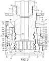
Fig. 2 is a detailed view ofFig. 1 ; -
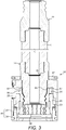
Figs 3 and4 show similar views toFig 1 and2 with the same connector in a closed configuration; and -
Figs 5 and6 show similar views toFigs 3 and4 with a second wireline conduit connected to the first. - An embodiment of the invention will now be described, by way of example only, with reference to the drawings.
- A
collect connector 10 is depicted in section inFig. 1 . Theconnector 10 is shown attached to a wireline conduit in the form of a lubricator tube L. The lubricator tube L is a cylindrical low alloy steel tube which in this case has an internal diameter of 3.563" (90.5mm) and an external diameter of 10" (254.0mm). - The lubricator tube L has threaded ends LT and LB. Two
adapters adapters adapters cylindrical bodies cylindrical bodies sockets Fig. 1 , these threadedsockets adapters - The
adapters sockets adapters - A
metal seal 19 is located adjacent the junction between threadedsocket 18b and theinner adapter bore 18c. - At second ends 16d,18d on the outer surface of the
adapters toothed profiles toothed profiles adapters profile - A
further metal seal 21 is located around the inner adapter bore 18c adjacent the second 18d. -
Lower adapter 14 has two external threads located between itsfirst end 18a andsecond end 18d. Towards thefirst end 18a (uppermost from the perspective of both Figs) is alock ring thread 18f. Toward thesecond end 18d is amain housing thread 18g. Boththreads lower adapter 14, such that they allow thelower adapter 14 to be a "male" to subsequently described "female" pieces. Boththreads lock ring thread 18f being of greater diameter than themain housing thread 18g, creating a step-wise change in the external diameter of thecylindrical body 18 of thelower adapter 14. - An
upper housing 20 attaches to thelower adapter 14 via themain housing thread 18g of the lower adapter and a threadedorifice 22 of the uppermain housing 20. Theupper housing 20 comprises aflange 24 at the centre of which is defined the threadedorifice 22. Acylindrical sidewall 26 extends from theflange 24, theflange 24 andcylindrical sidewall 26 having substantially equivalent outermost diameters. Anouter chamfer 28 is provided on the outer surface of theupper housing 20 at the junction offlange 24 andsidewall 26. A correspondingfillet 30 is provided on the inner surface of theupper housing 20 at the junction offlange 24 andsidewall 26. - A
lower housing thread 32 is provided on the inner surface of thesidewall 26 at the distal end of theupper housing 20 fromflange 24. - A
lower housing 34 attaches to theupper housing 20 via thelower housing thread 32 of theupper housing 20 and anexterior housing thread 36 provided on thelower housing 34. - The
lower housing 34 comprises acylindrical sidewall 38, a lowerinner housing flange 39 and a lowerouter housing flange 40. The lowerinner housing flange 39 defines alower housing orifice 42 at its centre. Thecylindrical sidewall 38 of thelower housing 34 is of a lesser diameter than the diameter of thecylindrical sidewall 26 of theupper housing 20. This allows thelower housing 34 to fit within and form a mating connection with theupper housing 20. - The
cylindrical sidewall 26 of theupper housing 20 is of a uniform diameter on the outermost surface, but comprises two discrete regions of different wall thickness. These two regions create a stepwise change in diameter on the innermost surface. A greater thicknessfirst section 26a extends from theflange 24 transitioning to a lesser thicknesssecond section 26b. Thelower housing thread 32 is located on the distal portion of the lesser thicknesssecond section 26b. - A
hydraulic bore 25 runs through the greater thicknessfirst section 26a of thesidewall 26 andflange 24 of theupper housing 20, and terminates at the junction of the greater thicknessfirst section 26a and the lesser thicknesssecond section 26b. The hydraulic bore 25 branches at that point perpendicularly both to communicate with the interior and exterior of theupper housing 20. - The
hydraulic bore 25 commences on the upper surface of theflange 24 with a mechanical connection point, in this embodiment a female quick connect fitting 25a, to allow hydraulic supplies to be fitted to it. A further mechanical connection point, in this example a male quick connect fitting 25b, is provided on the outer surface of thesidewall 26, also to allow hydraulic supplies to be fitted to it. The male quick connect fitting 25b is fitted with a blanking plug 25c, to provide a removable seal to thehydraulic bore 25. - As can be seen from the Figs, the lesser thickness
second section 26b has a greater axial length than thecylindrical sidewall 38 of thelower housing 34, and thus aninner piston recess 44 is formed between thecylindrical sidewall 38 of thelower housing 34, the lesser thicknesssecond section 26b and the greater thicknessfirst section 26a. Thehydraulic bore 25 is in fluid communication with thepiston recess 44. - A
piston sleeve 46 is located within the conjoined housing 49 (theconjoined housing 49 being the combined arrangement ofupper housing 20 and lower housing 34). -
Piston sleeve 46 is substantially cylindrical. It comprises a substantiallycylindrical piston body 48 with apiston flange 50 extending outwardly from thecylindrical piston body 48 at the approximate mid-point of thecylindrical piston body 48. Thepiston flange 50 is housed within theinner piston recess 44, thecylindrical sidewall 38 of thelower housing 34, the lesser thicknesssecond section 26b and the greater thicknessfirst section 26a restricting its movement, as will subsequently be described. - Housing O-rings 27 are provided on the upper and lower housing to enable sealing. First housing O-
ring 27a is mounted around the lower edge of the greater thicknessfirst section 26a on the inner surface of theupper housing 20, to enable a seal to be formed between theupper housing 20 and thepiston sleeve 46. The second housing O-ring 27b is mounted around the outer surface of an upper portion of thecylindrical sidewall 38 of thelower housing 34, enabling a seal to be formed between thelower housing 34 and theupper housing 20. The third housing O-ring 27c is mounted adjacent the second housing O-ring 27b on the inner surface of the upper portion of thecylindrical sidewall 38 of thelower housing 34, allowing a seal to be formed between thelower housing 24 and thepiston sleeve 46. - The
piston sleeve 46, although substantially cylindrical, has a non-linearinner surface 52 and non-linearouter surface 54. - The
inner surface 52 comprises four varying diameter sections.Uppermost section 52a is located at the end of thepiston sleeve 46 adjacent theupper housing flange 24. It has the smallest mean internal diameter and therefore the greatest mean wall thickness of thepiston sleeve 46 is located at theuppermost section 52a. Both axial ends of theuppermost section 52a are chamfered. It should be noted that in the example ofFigs. 1 and2 , theuppermost section 52a does not have a constant diameter but rather a linear varying diameter to form a slightly frustum-shaped internal diameter section. - A first
intermediate section 52b is located adjacent theuppermost section 52a. Firstintermediate section 52b has approximately equal axial length to theuppermost section 52a. Firstintermediate section 52b has a greater internal diameter than theuppermost section 52a, and does not have a frustum shape; rather it has a more regular cylindrical shape, typically with substantially parallel sides typically parallel to the inner surfaces of thehousing 49. - A second
intermediate section 52c is located adjacent (e.g. below) the firstintermediate section 52b, and below it from the perspective of the Figs. The secondintermediate section 52c is similar in appearance to theuppermost section 52a in that it does not have a constant diameter but rather a linear varying diameter to form a slightly frustum-shaped internal diameter section. It will be noted that in the present example, the innermost surface of the secondintermediate section 52c and theuppermost section 52a share a common plane. This is 4° from vertical in the present example. This angle may be varied in other examples, but will typically be between 3° and 6° from vertical, typically diverging towards thelower housing 24 when the collet connector is in its open configuration shown inFig 1 and2 . - Lastly, a
lowermost section 52d projects from the lower end of the secondintermediate section 52c. It is generally cylindrical, albeit with chamfered edges on its innermost and outermost surfaces at its lower extent, located distally from the secondintermediate section 52c. It has the least axial dimension of the four sections. - The outer surface comprises three discrete sections: an
upper section 54a, thepiston flange 50 and alower section 54b. All three have a cylindrical outer surface: theupper section 54a abutting and forming a sliding fit with thecylindrical sidewall 26 of theupper housing 20; thepiston flange 50 abutting and forming a sliding fit with thepiston recess 44; and thelower section 54b abutting and forming a sliding fit with thecylindrical sidewall 38 of thelower housing 34. - The
piston flange 50 has the greatest outermost diameter of the three sections, as its movement (as will subsequently be described) is restricted by thecylindrical sidewall 38 of thelower housing 34 and thecylindrical sidewall 26 of theupper housing 20 within thepiston recess 44. A piston flange O-ring 50a is mounted around the outer circumference of thepiston flange 50 enabling a seal to be formed between thepiston flange 50 and thepiston recess 44. - The
lower section 54b has the least outermost diameter of the three sections, to match the inner diameter of thecylindrical sidewall 38 of thelower housing 34. - The
upper section 54a has a slightly greater outermost diameter than thelower section 54b, to match the inner diameter of thecylindrical sidewall 26 of theupper housing 20, which itself is slightly greater than the inner diameter of thecylindrical sidewall 38 of thelower housing 34. - An
indicator rod 55 is mounted on top of thepiston sleeve 46. It projects through an indicator rod bore (not shown) which extends through theflange 24 of theupper housing 20. Theindicator rod 55 is a generally cylindrical member made of low alloy steel. - Around the approximate mid-section of the
lower adapter 14 there is alock ring thread 18f. Alock ring 57 is mounted around thislock ring thread 18f. Thelock ring 57 can traverse thelock ring thread 18f and may bear againstindicator rod 55, as shown in the Figs. - A
collet ring 56 is arranged within thepiston sleeve 46. It is formed from a solid cylindrical ring of material which is then machined into a plurality ofindividual collet fingers 58. Thecollet fingers 58 project (downwardly from the perspective of the Figs) from asolid ring member 60. Thering member 60 maintains the position of one end of thecollet fingers 58 in a constant position, and thecollet fingers 58 splay radially outwardly forming a generally frusto-conical shape. In the presently described example there are sixteencollet fingers 58 on thecollet ring 56. - The
collet fingers 58 and therefore thecollet ring 56 also, although forming a substantially frusto-conical shape, have non-linearinner surfaces 62 and non-linear outer surfaces 64. - The
inner surfaces 62 are machined with annulartoothed profiles toothed profile 62a is substantially sawtooth-shaped and corresponds in shape and arrangement to the annulartoothed profile 18e oflower adapter 14. As depicted by the Figs, the annulartoothed profile 18e oflower adapter 14 forms an interference fit with the uppermost annulartoothed profiles 62a preventing relative axial displacement of the two. - The lowermost annular
toothed profile 62b has a similar profile, albeit reversed, such that the more acute angles of the recesses are spaced distally opposite from one another. - The
outer surfaces 64 of thecollet fingers 58 are typically non-linear in shape. A generally frustum outer shape is formed when thefingers 58 splay radially outwards, approximately halfway down and encompassing approximately 25% of the axial length of thecollet fingers 58 there is acollet recess 58a which is in the form of a section with a lesser outer diameter. The recess has an outer surface with a plane approximately parallel to a plane of the outer surface of the general frustum shape of the remainder of the outer surfaces 64. - In use, a further section of lubricator tube L' may optionally have an adapter attached. The adapter, being similar to that of the
upper adapter 12 can be introduced into thelower housing orifice 42 until its annular toothed profiles are located within the space between the splayedcollet fingers 58 and adjacent the lowermost annulartoothed profile 62b on the inner surface of thecollet fingers 58, as is best shown inFigs 5 and6 . Alternatively the profiles can be formed on the lubricator L' and the adapter can be omitted. - A hydraulic supply can then attached to the
hydraulic bore 25 via either the female quick connect fitting 25a or the male quick connect fitting 25b. Hydraulic fluid will be pumped into thebore 25 and be forced into thepiston recess 44 and bear against the upper surface of thepiston flange 50. The pressure will cause thepiston flange 50 to move downwardly, and thus thepiston sleeve 46 will also descend. - The non-linear
inner surface 52 of the piston sleeve will slide over theouter surfaces 64 of thecollet fingers 58. As is most easily seen inFigs 3-6 , the tapered and axially spacedsections outer surface 64 of the collet fingers, which are typically tapered at the same non-aligned angle with respect to the axis of the connector. Typically the axial spacing between the engaging tapered faces on the inner surface of thepiston sleeve 46 and the outer surface of thecollet fingers 58 are also matched, so that the tapered surfaces engage throughout the stroke of thepiston sleeve 46. Therefore, a wedge effect is created by the opposed tapered surfaces of thepiston sleeve 46 and thecollect fingers 58, which converts the axial movement of thepiston sleeve 46 under the force of the hydraulic fluid into a radial force that compresses thecollet fingers 58 radially inwards against the conduits. As the tapered varyingdiameter sections collet fingers 58 radially inwards from their splayed position shown inFigs 1 and2 to a radially compressed configuration shown inFigs 3-6 , in which thecollet fingers 58 are have moved radially inwards towards the axis of the lubricator tube, but as can be seen inFigs 3-6 , the outer surface of thecollet fingers 58 is typically still tapered in the final closed configuration, which allows the piston to continue the compressive force applied to thecollet fingers 58 throughout the length of its axial stroke, and thus energises the connection even in the fully closed configuration. - Eventually, the lowermost annular
toothed profile 62b on the inner surface of thecollet finger 58 engages the annular toothed profiles of the outer surface of the second adapter forming an interference fit similar to that of the annulartoothed profile 18e oflower adapter 14 with the uppermost annulartoothed profiles 62a. It should be noted from the closed configurations shown inFigs 3-6 , that the toothed profiles are not symmetrical and that when the profiles are fully engaged, theteeth 62 on the inner surfaces of thecollet fingers 58 have not yet travelled to the radially innermost point of the recess, yet, theteeth 18e on the outer surface of theadapter 18 have engaged fully in the recesses on the inner surface of thecollet fingers 58. Also, the two sides of the recess are set at different angles, so that when the profiles are fully engaged, the force is applied to the inner faces of the recess and in preference to the outer faces of the recesses, thereby converting most of the radial compressive forces back into axial forces to compress the seal between the two conduits L and L', as is best seen inFig 6 . Thus, a connection between the introduced further section of lubricator tube L' and the first lubricator tube L is formed. As thecollet fingers 58 are driven radially deeper into the toothed profiles theadapters collet fingers 58 and the toothed profiles. This movement energises themetal seal 21 between the two sections of lubricator tube. - As the
piston sleeve 46 descends so too does theindicator rod 55. Once the desired connection between the introduced further section of lubricator tube and lubricator tube L is formed, thelock ring 57 may be rotated aroundlock ring thread 18f, to axially traverse thelock ring thread 18f and move it down to bear against the upper surface of the indicator rod(s) 55. Thelock ring 57 therefore forms an abutment preventing thepiston sleeve 46 ascending and thereby releasing the introduced further section of lubricator tube from its connection with lubricator tube L. Contrast the two positions of thelock ring 57 in the open configurations inFigs 1 and2 and the closed configurations inFigs 3-6 . One or more than oneindicator rod 55 can be provided in different examples, but only one is in section in the drawings shown. - It will be appreciated that the movement of the
piston flange 50 is restricted by thecylindrical sidewall 38 of thelower housing 34 and thecylindrical sidewall 26 of theupper housing 20 within thepiston recess 44. Since the movement of thepiston flange 50 is restricted so too is the movement of thepiston sleeve 46, and so when thepiston sleeve 46 has moved into the second closed configuration as shown inFigs 3-6 , thelock ring 57 and indicator rod(s) 55 lock it in position and prevent loosening of the connection from the closed configuration. -
Fig 6 shows a different section of the connector, showing atest port 70 exposed to an outer wall of the second (lower) conduit L', typically formed in the adaptor of the second conduit L', and having abore 71 connecting thetest port 70 to a space behind theseal 21 between the conduits L, L'. Thistest port 70 is typically closed by a removable cap and may optionally have a valve, and permits the pressure in the chamber behind theseal 21 to communicate with the test port, thereby allowing connection of monitoring equipment to theport 70 to determine and optionally record the prevailing pressure in the space radially outside theseal 21. This can be used to report and measure any pressure changes that may indicate loss of integrity of theseal 21, without requiring dis-assembly of the connection. Typically an operator can inject pressure into theport 70 to bear on theseal 21 from the outside. Optionally theport 70 is provided in the adaptor, but could be provided in the body of the conduit L' or in another part of the apparatus. Similar ports can be provided in the first conduit L, but are not shown in section in the drawings. - The upper end of the
collet device 60 typically has aheel 67 with a taper that extends radially outward from thefingers 58, and with aninner surface 65, which is also tapered radially outwards. Theheel 67 interacts with thepiston sleeve 46 in the open configuration shown inFigs 1 and2 , so that when thepiston sleeve 46 retracts fully upwards in thehousing 49, theheel 67 is forced radially inwards to press the taperedinner surface 65 against the parallel outer surface of theadapter 14, with the result that thecollet fingers 58 pivot around the fulcrum created by the end of the taperedinner surface 65 to spring open at the lower end and release the engaged profiles connecting the two conduits L, L1. This feature facilitates disengagement of thecollet fingers 58 to release the connection. - Although relative terms "upper", "lower", "uppermost", "lowermost", "downward", "upward", etc. are used hereinbefore, it will be understood that these relate only to the orientation of the embodiment as depicted in the attach Figures. The skilled addressee will appreciate that the embodiment will function independent of orientation and is not limited to any particular orientation.
- Modifications and improvements may be made to the foregoing without departing from the scope of the invention. For example, the invention is not limited to the specific materials such as INCONEL ® for the adaptor bodies or low alloy steel for the indicator rod. Suitable materials and alloys may be used, such as, for example, stainless steel for the indicator rod.
- Further, the specific dimensions and angles may be varied depending on application.
- The present invention may find utility in wireline intervention equipment. Such equipment is temporary, quick rigup/rigdown gear, and so commonly uses manual quick union collars with elastomeric seals.
- The present invention enables quick disconnection of such unions while being capable of energising metal seals which may be primary joint seals between temporary pressure equipment.
Claims (15)
- A connector device for use in wireline intervention operations, for coupling a first wireline conduit to a second wireline conduit, the connector comprising a housing (49) on the first wireline conduit, a piston sleeve (46) located within the housing (49), a collet device (56) configured to receive and retain the second wireline conduit, the collet device (56) having a plurality of collet fingers (58) arranged within said piston sleeve (46), the piston sleeve (46) being movable within the housing (49) from a first position, where the collet fingers (58)are in a receiving position, to a second position, where the collet fingers (58) are in a clamping position, characterised by a restrictor (57, 55) configured to control the movement of the piston sleeve (46), the restrictor (57, 55) being adjustable between a first configuration in which it permits free movement of the piston sleeve (46), and a second configuration in which it restricts movement of the piston sleeve (46).
- A connector device as claimed in claim 1, wherein the second configuration of the restrictor (57, 55) locks the piston sleeve (46) in the second position when the collet fingers (58) are in the clamping position.
- A connector device as claimed in any one of claims 1-2, wherein the restrictor (57, 55) includes at least one indicator rod (55) which projects out of the housing (49), and wherein the piston sleeve (46) engages the indicator rod (55) in the second position.
- A connector device as claimed in any one of claims 1-3, wherein the restrictor (57, 55) comprises a threaded flange (57) axially movable on a thread relative to the piston sleeve (46).
- A connector device as claimed in claim 4, wherein in the second position, the threaded flange (57) engages an end of at least one indicator rod (55) to urge the indicator rod (55) against the piston sleeve (46).
- A connector device as claimed in any one of claims 1-5, wherein the piston sleeve (46) is sealed within the housing (49) and is urged from the first to the second position by hydraulic pressure delivered to the housing (49).
- A connector device as claimed in any one of claims 1-6, wherein the piston sleeve (46) has a discontinuous inner surface with at least two tapered regions at spaced apart locations on the piston sleeve (46), which are tapered at non-aligned angles to match tapered portions of the outer surface of the collet device (56), and whereby the tapered surfaces in each case diverge away from the axis of the connector device (10 in a direction towards an open end of the collet device (56), whereby as the piston sleeve (46) moves in the direction towards the open end of the collet device (56), the tapered surfaces on the collet device (56) and the piston sleeve (46) engage to apply a radial force to the collet device (56) to close the collet fingers (58) at the open end of the collet device (56).
- A connector device as claimed in claim 7, wherein the tapered inner surface incorporates radial steps between at least two of the discontinuous sections.
- A connector device as claimed in any one of claims 7-8, wherein the inner surface of the piston sleeve (46) comprises four discontinuous sections arranged sequentially on the piston sleeve (46) between a first end of the piston sleeve (46) closest to the closed end of the collet device (56) and a second end of the piston sleeve (46), closest to the open end of the collet device (56), and wherein the discontinuous sections are arranged with a narrowest diameter section at the first end of said piston sleeve (46), followed by a larger diameter section, followed by a narrower diameter section, followed by a final section having the largest diameter.
- A connector device as claimed in any one of claims 1-9, wherein the housing (49) comprises at least one hydraulic bore (25) configured to receive pressurised hydraulic fluid to urge the piston sleeve (46) between the first position and the second position.
- A connector device as claimed in any one of claims 1-10, comprising a test port (70), accessible from an external wall of the device (10), in fluid communication with the seal (19) between the first and second wireline conduits, and adapted to transmit pressure at the seal (19) to the test port (70).
- A wireline assembly comprising first and second wireline tubulars, connected by a wireline connector device according to any one of claims 1-11, the wireline conduits having a bore adapted to receive a wireline.
- A method of coupling a first wireline conduit to a second wireline conduit, the method comprising providing a connector (10) comprising a housing (49) on the first wireline conduit, a piston sleeve (46) located within the housing (49), and a collet device (56) configured to receive and retain the second wireline conduit, the collet device (56) having a plurality of collet fingers (58) arranged within said piston sleeve (46), and wherein the method includes moving the piston sleeve (46) within the housing (49) from a first position, where the collet fingers (58) are in a receiving position, to a second position, where the collet fingers (58) are in a clamping position, characterised in that the connector has a restrictor (57, 55) configured to control the movement of the piston sleeve (46), the restrictor (57, 55) being adjustable between a first configuration in which it permits free movement of the piston sleeve (46), and a second configuration in which it restricts movement of the piston sleeve (46), and wherein the method includes restricting free movement of the piston sleeve (46) in the second configuration of the restrictor (57, 55).
- A method according to claim 13, wherein the restrictor (57, 55) includes at least one indicator rod (55) which projects out of the housing (49), and wherein the method includes pressing the indicator rod (55) against the piston sleeve (46) in the second position.
- A method according to any one of claims 13-14, wherein the restrictor (57, 55) comprises a threaded flange (57) axially movable on a thread relative to the piston sleeve (46), and wherein the method includes rotating the threaded flange (57) on the thread to engage the threaded flange (57)_against an end of the at least one indicator rod (55) and urging the indicator rod (55) against the piston sleeve (46).
Priority Applications (1)
| Application Number | Priority Date | Filing Date | Title |
|---|---|---|---|
| PL12821176T PL2798143T3 (en) | 2011-12-30 | 2012-12-28 | Connector device for use in wireline intervention operations |
Applications Claiming Priority (2)
| Application Number | Priority Date | Filing Date | Title |
|---|---|---|---|
| GBGB1122466.4A GB201122466D0 (en) | 2011-12-30 | 2011-12-30 | Connector |
| PCT/GB2012/053272 WO2013098560A2 (en) | 2011-12-30 | 2012-12-28 | Connector device for use in wireline intervention operations |
Publications (2)
| Publication Number | Publication Date |
|---|---|
| EP2798143A2 EP2798143A2 (en) | 2014-11-05 |
| EP2798143B1 true EP2798143B1 (en) | 2019-01-23 |
Family
ID=45695092
Family Applications (1)
| Application Number | Title | Priority Date | Filing Date |
|---|---|---|---|
| EP12821176.0A Active EP2798143B1 (en) | 2011-12-30 | 2012-12-28 | Connector device for use in wireline intervention operations |
Country Status (8)
| Country | Link |
|---|---|
| US (1) | US9689211B2 (en) |
| EP (1) | EP2798143B1 (en) |
| AU (1) | AU2012370411B2 (en) |
| CA (1) | CA2854861C (en) |
| GB (1) | GB201122466D0 (en) |
| PL (1) | PL2798143T3 (en) |
| SG (1) | SG11201402376RA (en) |
| WO (1) | WO2013098560A2 (en) |
Families Citing this family (19)
| Publication number | Priority date | Publication date | Assignee | Title |
|---|---|---|---|---|
| US9068423B2 (en) | 2012-02-03 | 2015-06-30 | National Oilwell Varco, L.P. | Wellhead connector and method of using same |
| US9074450B2 (en) | 2012-02-03 | 2015-07-07 | National Oilwell Varco, L.P. | Blowout preventer and method of using same |
| CN104271870B (en) | 2012-04-04 | 2017-09-22 | 国民油井华高公司 | Misalignment tolerant wellsite connector assemblies, systems and methods |
| BR112014024680B1 (en) | 2012-04-05 | 2020-12-01 | National Oilwell Varco, L.P. | well location connector, and, method for connecting components from a well location |
| DE102013108326A1 (en) * | 2013-08-02 | 2015-02-05 | Peri Gmbh | Scaffolding tube of a scaffolding and scaffolding element |
| US10094501B2 (en) * | 2013-09-11 | 2018-10-09 | Halliburton Energy Services, Inc. | High pressure remote connector with self-aligning geometry |
| WO2016145420A1 (en) * | 2015-03-11 | 2016-09-15 | Hunting Titan, Inc. | Quick connect system for setting tool |
| WO2017052511A1 (en) * | 2015-09-22 | 2017-03-30 | Halliburton Energy Services, Inc. | Downhole tool with assembly for determining seal integrity |
| US10094196B2 (en) * | 2016-02-26 | 2018-10-09 | Fa Solutions As | Rotating control device |
| US10745978B2 (en) * | 2017-08-07 | 2020-08-18 | Weatherford Technology Holdings, Llc | Downhole tool coupling system |
| US11180979B1 (en) | 2018-11-30 | 2021-11-23 | Quarter Turn Pressure Control, LLC | High pressure jumper manifold |
| GB201905785D0 (en) * | 2019-04-25 | 2019-06-05 | Nat Oilwell Varco Uk Limited | Connection assembly |
| CN110529663B (en) * | 2019-09-11 | 2020-11-24 | 福州宇卓科技有限公司 | Flexible air pipe connecting device based on clamp clamping principle |
| US12129727B2 (en) | 2019-11-06 | 2024-10-29 | Fmc Technologies, Inc. | Collet-type wellhead connector system |
| US11384858B2 (en) * | 2020-02-28 | 2022-07-12 | Forum Us, Inc. | Locking assembly apparatus and methods for fluid ends |
| WO2025058862A1 (en) * | 2023-09-12 | 2025-03-20 | Onesubsea Ip Uk Limited | Subsea connection enhancement assembly |
| US12338689B2 (en) * | 2023-09-25 | 2025-06-24 | Halliburton Energy Services, Inc. | Downhole wet-mate systems and methods using wet-mate deployment carrier |
| WO2025075603A1 (en) * | 2023-10-02 | 2025-04-10 | Halliburton Energy Services, Inc. | Wet mate carrier for radial deployment of downhole wet mate connector |
| NO348571B1 (en) * | 2024-06-03 | 2025-03-17 | Groundbreaker As | A female coupling element, a coupling assembly comprising the female coupling element, and a method for providing the coupling assembly |
Family Cites Families (42)
| Publication number | Priority date | Publication date | Assignee | Title |
|---|---|---|---|---|
| US2951274A (en) * | 1957-09-23 | 1960-09-06 | Aeroquip Corp | Fastener of dog construction |
| US3589441A (en) | 1968-04-01 | 1971-06-29 | North American Rockwell | Deep water operating and servicing system for operating and servicing marine wells |
| US3999260A (en) * | 1976-01-09 | 1976-12-28 | Bj-Hughes Inc. | Rotary power slip assembly |
| US4153278A (en) * | 1977-09-19 | 1979-05-08 | Vetco, Inc. | Hydraulically operated misalignment connector |
| US4337971A (en) * | 1980-08-07 | 1982-07-06 | Halliburton Company | Remote connector |
| US4566168A (en) * | 1985-01-09 | 1986-01-28 | Halliburton Company | Quick connect adapter |
| US4647254A (en) | 1985-04-18 | 1987-03-03 | Mobil Oil Corporation | Marine riser structural core connector |
| US4708376A (en) | 1986-01-31 | 1987-11-24 | Vetco Gray Inc. | Hydraulic collet-type connector |
| US4693497A (en) * | 1986-06-19 | 1987-09-15 | Cameron Iron Works, Inc. | Collet connector |
| GB2199102B (en) | 1986-12-18 | 1990-02-14 | Hunting Oilfield Services Ltd | Improvements in and relating to connectors |
| GB8825623D0 (en) | 1988-11-02 | 1988-12-07 | Cameron Iron Works Inc | Collet type connector |
| US4902044A (en) | 1989-05-04 | 1990-02-20 | Drill-Quip, Inc. | Well apparatus |
| US5441311B1 (en) | 1994-07-01 | 1997-10-07 | Dril Quip Inc | Connector with opposite moving cam rings |
| US6070669A (en) | 1997-02-15 | 2000-06-06 | Abb Vetco Gray Inc. | Adjustable wellhead connector |
| US5971076A (en) | 1997-08-29 | 1999-10-26 | Cooper Cameron Corporation | Subsea wellhead structure for transferring large external loads |
| US6129149A (en) | 1997-12-31 | 2000-10-10 | Kvaerner Oilfield Products | Wellhead connector |
| US6138762A (en) * | 1998-02-12 | 2000-10-31 | Abb Vetco Gray Inc. | Wellhead connector with additional load shoulders |
| US6089321A (en) | 1998-03-16 | 2000-07-18 | Hydril Company | Pressure balanced choke and kill line connector |
| GB2335684B (en) | 1998-03-26 | 2002-07-03 | Vetco Gray Inc Abb | External tieback connector |
| US6035938A (en) | 1998-03-26 | 2000-03-14 | Dril-Quip, Inc. | Wellhead system and method for use in drilling a subsea well |
| US6260624B1 (en) | 1998-08-06 | 2001-07-17 | Abb Vetco Gray, Inc. | Internal production riser primary tieback |
| US6540024B2 (en) | 2000-05-26 | 2003-04-01 | Abb Vetco Gray Inc. | Small diameter external production riser tieback connector |
| US6609731B2 (en) | 2000-09-19 | 2003-08-26 | 2R.L-Quip | Connector |
| US6595293B2 (en) * | 2001-05-23 | 2003-07-22 | Cooper Cameron Corporation | Apparatus and method for connecting riser between a floating vessel and a subsea structure |
| NO20015954A (en) | 2001-12-05 | 2003-03-17 | Fmc Kongsberg Subsea As | Pipe coupling |
| US6609734B1 (en) | 2002-02-11 | 2003-08-26 | Benton F. Baugh | Torus type connector |
| US6824171B2 (en) * | 2002-08-23 | 2004-11-30 | Dril-Quip, Inc. | Riser connector |
| DE20213393U1 (en) | 2002-08-30 | 2004-01-15 | Cameron Gmbh | connecting device |
| US20040102069A1 (en) | 2002-11-21 | 2004-05-27 | Singeetham Shiva P. | Hydraulic connector |
| US6915865B2 (en) * | 2003-01-28 | 2005-07-12 | Boyd's Bit Service, Inc. | Locking swivel apparatus with a supplemental internal locking mechanism |
| US6902199B2 (en) | 2003-05-16 | 2005-06-07 | Offshore Systems Inc. | ROV activated subsea connector |
| US20050001427A1 (en) | 2003-05-20 | 2005-01-06 | Fmc Technologies, Inc. | Low profile connector |
| US7537057B2 (en) | 2004-07-23 | 2009-05-26 | Fmc Technologies, Inc. | Slimline tieback connector |
| GB2429990A (en) | 2005-09-07 | 2007-03-14 | Keron Engineering Ltd | Drilling guide frame assembly |
| GB2450854B (en) | 2006-05-19 | 2011-11-02 | Vetco Gray Inc | Rapid makeup riser connector |
| US7614453B2 (en) | 2006-06-01 | 2009-11-10 | Cameron International Corporation | Stress distributing wellhead connector |
| US7748466B2 (en) | 2006-09-14 | 2010-07-06 | Thrubit B.V. | Coiled tubing wellbore drilling and surveying using a through the drill bit apparatus |
| WO2010005619A1 (en) | 2008-06-16 | 2010-01-14 | Cameron International Corporation | Hydraulic connector |
| NO344628B1 (en) | 2008-06-26 | 2020-02-10 | Vetco Gray Inc | Feedback assembly and procedure for connecting an extension tube and wellhead |
| NO330742B1 (en) | 2009-01-16 | 2011-06-27 | Aker Subsea As | Coupling device for tubular elements |
| US8720574B2 (en) | 2009-02-25 | 2014-05-13 | Aker Solutions Inc. | Subsea connector |
| US9334705B1 (en) * | 2015-01-13 | 2016-05-10 | Onesubsea Ip Uk Limited | Subsea connector |
-
2011
- 2011-12-30 GB GBGB1122466.4A patent/GB201122466D0/en not_active Ceased
-
2012
- 2012-12-28 CA CA2854861A patent/CA2854861C/en not_active Expired - Fee Related
- 2012-12-28 US US14/359,895 patent/US9689211B2/en active Active
- 2012-12-28 SG SG11201402376RA patent/SG11201402376RA/en unknown
- 2012-12-28 WO PCT/GB2012/053272 patent/WO2013098560A2/en not_active Ceased
- 2012-12-28 AU AU2012370411A patent/AU2012370411B2/en not_active Ceased
- 2012-12-28 PL PL12821176T patent/PL2798143T3/en unknown
- 2012-12-28 EP EP12821176.0A patent/EP2798143B1/en active Active
Non-Patent Citations (1)
| Title |
|---|
| None * |
Also Published As
| Publication number | Publication date |
|---|---|
| SG11201402376RA (en) | 2014-08-28 |
| PL2798143T3 (en) | 2019-09-30 |
| US20140318809A1 (en) | 2014-10-30 |
| CA2854861A1 (en) | 2013-07-04 |
| GB201122466D0 (en) | 2012-02-08 |
| WO2013098560A3 (en) | 2014-02-27 |
| US9689211B2 (en) | 2017-06-27 |
| CA2854861C (en) | 2019-08-13 |
| EP2798143A2 (en) | 2014-11-05 |
| AU2012370411B2 (en) | 2015-02-19 |
| AU2012370411A1 (en) | 2013-09-19 |
| WO2013098560A2 (en) | 2013-07-04 |
Similar Documents
| Publication | Publication Date | Title |
|---|---|---|
| CA2854861C (en) | Connector device for use in wireline intervention operations | |
| EP3430299B1 (en) | Push-to-connect fitting device, arrangement and method | |
| KR102121628B1 (en) | Push to connect conduit fitting with ferrule | |
| US10301889B2 (en) | Dynamic riser mechanical connector | |
| US20210123550A1 (en) | Fitting Device, Arrangement and Method | |
| WO2010078549A4 (en) | Push-twist connector | |
| EP3584485B1 (en) | Tubular connecting arrangement and method of sealingly connecting tubulars | |
| AU2012262869B2 (en) | Ball valve | |
| AU2021229137B2 (en) | Apparatus and Method for Coupling | |
| US9989175B2 (en) | Fluid component adapter and method | |
| NO344166B1 (en) | Pipe quick connector | |
| US8668230B2 (en) | Apparatus and methods for splicing conduits and hoses subsea | |
| US20080309068A1 (en) | Pipe Insert | |
| EP3152473A1 (en) | A connector | |
| EP3405644B1 (en) | Pipe coupling | |
| EP3175162B1 (en) | A connector device | |
| US20190323640A1 (en) | Sliding high pressure pipe connection | |
| US12007047B2 (en) | Restrained pipe coupling |
Legal Events
| Date | Code | Title | Description |
|---|---|---|---|
| PUAI | Public reference made under article 153(3) epc to a published international application that has entered the european phase |
Free format text: ORIGINAL CODE: 0009012 |
|
| 17P | Request for examination filed |
Effective date: 20140519 |
|
| AK | Designated contracting states |
Kind code of ref document: A2 Designated state(s): AL AT BE BG CH CY CZ DE DK EE ES FI FR GB GR HR HU IE IS IT LI LT LU LV MC MK MT NL NO PL PT RO RS SE SI SK SM TR |
|
| DAX | Request for extension of the european patent (deleted) | ||
| GRAP | Despatch of communication of intention to grant a patent |
Free format text: ORIGINAL CODE: EPIDOSNIGR1 |
|
| STAA | Information on the status of an ep patent application or granted ep patent |
Free format text: STATUS: GRANT OF PATENT IS INTENDED |
|
| INTG | Intention to grant announced |
Effective date: 20180731 |
|
| GRAS | Grant fee paid |
Free format text: ORIGINAL CODE: EPIDOSNIGR3 |
|
| GRAA | (expected) grant |
Free format text: ORIGINAL CODE: 0009210 |
|
| STAA | Information on the status of an ep patent application or granted ep patent |
Free format text: STATUS: THE PATENT HAS BEEN GRANTED |
|
| RAP1 | Party data changed (applicant data changed or rights of an application transferred) |
Owner name: NATIONAL OILWELL VARCO UK LIMITED |
|
| AK | Designated contracting states |
Kind code of ref document: B1 Designated state(s): AL AT BE BG CH CY CZ DE DK EE ES FI FR GB GR HR HU IE IS IT LI LT LU LV MC MK MT NL NO PL PT RO RS SE SI SK SM TR |
|
| REG | Reference to a national code |
Ref country code: GB Ref legal event code: FG4D |
|
| REG | Reference to a national code |
Ref country code: CH Ref legal event code: EP |
|
| REG | Reference to a national code |
Ref country code: AT Ref legal event code: REF Ref document number: 1091591 Country of ref document: AT Kind code of ref document: T Effective date: 20190215 |
|
| REG | Reference to a national code |
Ref country code: IE Ref legal event code: FG4D |
|
| REG | Reference to a national code |
Ref country code: DE Ref legal event code: R096 Ref document number: 602012056306 Country of ref document: DE |
|
| REG | Reference to a national code |
Ref country code: NL Ref legal event code: MP Effective date: 20190123 |
|
| PG25 | Lapsed in a contracting state [announced via postgrant information from national office to epo] |
Ref country code: NL Free format text: LAPSE BECAUSE OF FAILURE TO SUBMIT A TRANSLATION OF THE DESCRIPTION OR TO PAY THE FEE WITHIN THE PRESCRIBED TIME-LIMIT Effective date: 20190123 |
|
| REG | Reference to a national code |
Ref country code: NO Ref legal event code: T2 Effective date: 20190123 |
|
| PG25 | Lapsed in a contracting state [announced via postgrant information from national office to epo] |
Ref country code: FI Free format text: LAPSE BECAUSE OF FAILURE TO SUBMIT A TRANSLATION OF THE DESCRIPTION OR TO PAY THE FEE WITHIN THE PRESCRIBED TIME-LIMIT Effective date: 20190123 Ref country code: LT Free format text: LAPSE BECAUSE OF FAILURE TO SUBMIT A TRANSLATION OF THE DESCRIPTION OR TO PAY THE FEE WITHIN THE PRESCRIBED TIME-LIMIT Effective date: 20190123 Ref country code: PT Free format text: LAPSE BECAUSE OF FAILURE TO SUBMIT A TRANSLATION OF THE DESCRIPTION OR TO PAY THE FEE WITHIN THE PRESCRIBED TIME-LIMIT Effective date: 20190523 Ref country code: ES Free format text: LAPSE BECAUSE OF FAILURE TO SUBMIT A TRANSLATION OF THE DESCRIPTION OR TO PAY THE FEE WITHIN THE PRESCRIBED TIME-LIMIT Effective date: 20190123 Ref country code: SE Free format text: LAPSE BECAUSE OF FAILURE TO SUBMIT A TRANSLATION OF THE DESCRIPTION OR TO PAY THE FEE WITHIN THE PRESCRIBED TIME-LIMIT Effective date: 20190123 |
|
| REG | Reference to a national code |
Ref country code: AT Ref legal event code: MK05 Ref document number: 1091591 Country of ref document: AT Kind code of ref document: T Effective date: 20190123 |
|
| PG25 | Lapsed in a contracting state [announced via postgrant information from national office to epo] |
Ref country code: LV Free format text: LAPSE BECAUSE OF FAILURE TO SUBMIT A TRANSLATION OF THE DESCRIPTION OR TO PAY THE FEE WITHIN THE PRESCRIBED TIME-LIMIT Effective date: 20190123 Ref country code: RS Free format text: LAPSE BECAUSE OF FAILURE TO SUBMIT A TRANSLATION OF THE DESCRIPTION OR TO PAY THE FEE WITHIN THE PRESCRIBED TIME-LIMIT Effective date: 20190123 Ref country code: BG Free format text: LAPSE BECAUSE OF FAILURE TO SUBMIT A TRANSLATION OF THE DESCRIPTION OR TO PAY THE FEE WITHIN THE PRESCRIBED TIME-LIMIT Effective date: 20190423 Ref country code: IS Free format text: LAPSE BECAUSE OF FAILURE TO SUBMIT A TRANSLATION OF THE DESCRIPTION OR TO PAY THE FEE WITHIN THE PRESCRIBED TIME-LIMIT Effective date: 20190523 Ref country code: GR Free format text: LAPSE BECAUSE OF FAILURE TO SUBMIT A TRANSLATION OF THE DESCRIPTION OR TO PAY THE FEE WITHIN THE PRESCRIBED TIME-LIMIT Effective date: 20190424 Ref country code: HR Free format text: LAPSE BECAUSE OF FAILURE TO SUBMIT A TRANSLATION OF THE DESCRIPTION OR TO PAY THE FEE WITHIN THE PRESCRIBED TIME-LIMIT Effective date: 20190123 |
|
| REG | Reference to a national code |
Ref country code: DE Ref legal event code: R097 Ref document number: 602012056306 Country of ref document: DE |
|
| PG25 | Lapsed in a contracting state [announced via postgrant information from national office to epo] |
Ref country code: DK Free format text: LAPSE BECAUSE OF FAILURE TO SUBMIT A TRANSLATION OF THE DESCRIPTION OR TO PAY THE FEE WITHIN THE PRESCRIBED TIME-LIMIT Effective date: 20190123 Ref country code: EE Free format text: LAPSE BECAUSE OF FAILURE TO SUBMIT A TRANSLATION OF THE DESCRIPTION OR TO PAY THE FEE WITHIN THE PRESCRIBED TIME-LIMIT Effective date: 20190123 Ref country code: SK Free format text: LAPSE BECAUSE OF FAILURE TO SUBMIT A TRANSLATION OF THE DESCRIPTION OR TO PAY THE FEE WITHIN THE PRESCRIBED TIME-LIMIT Effective date: 20190123 Ref country code: AL Free format text: LAPSE BECAUSE OF FAILURE TO SUBMIT A TRANSLATION OF THE DESCRIPTION OR TO PAY THE FEE WITHIN THE PRESCRIBED TIME-LIMIT Effective date: 20190123 Ref country code: IT Free format text: LAPSE BECAUSE OF FAILURE TO SUBMIT A TRANSLATION OF THE DESCRIPTION OR TO PAY THE FEE WITHIN THE PRESCRIBED TIME-LIMIT Effective date: 20190123 Ref country code: CZ Free format text: LAPSE BECAUSE OF FAILURE TO SUBMIT A TRANSLATION OF THE DESCRIPTION OR TO PAY THE FEE WITHIN THE PRESCRIBED TIME-LIMIT Effective date: 20190123 Ref country code: RO Free format text: LAPSE BECAUSE OF FAILURE TO SUBMIT A TRANSLATION OF THE DESCRIPTION OR TO PAY THE FEE WITHIN THE PRESCRIBED TIME-LIMIT Effective date: 20190123 |
|
| PG25 | Lapsed in a contracting state [announced via postgrant information from national office to epo] |
Ref country code: SM Free format text: LAPSE BECAUSE OF FAILURE TO SUBMIT A TRANSLATION OF THE DESCRIPTION OR TO PAY THE FEE WITHIN THE PRESCRIBED TIME-LIMIT Effective date: 20190123 |
|
| PLBE | No opposition filed within time limit |
Free format text: ORIGINAL CODE: 0009261 |
|
| STAA | Information on the status of an ep patent application or granted ep patent |
Free format text: STATUS: NO OPPOSITION FILED WITHIN TIME LIMIT |
|
| PG25 | Lapsed in a contracting state [announced via postgrant information from national office to epo] |
Ref country code: AT Free format text: LAPSE BECAUSE OF FAILURE TO SUBMIT A TRANSLATION OF THE DESCRIPTION OR TO PAY THE FEE WITHIN THE PRESCRIBED TIME-LIMIT Effective date: 20190123 |
|
| 26N | No opposition filed |
Effective date: 20191024 |
|
| PG25 | Lapsed in a contracting state [announced via postgrant information from national office to epo] |
Ref country code: SI Free format text: LAPSE BECAUSE OF FAILURE TO SUBMIT A TRANSLATION OF THE DESCRIPTION OR TO PAY THE FEE WITHIN THE PRESCRIBED TIME-LIMIT Effective date: 20190123 |
|
| PG25 | Lapsed in a contracting state [announced via postgrant information from national office to epo] |
Ref country code: TR Free format text: LAPSE BECAUSE OF FAILURE TO SUBMIT A TRANSLATION OF THE DESCRIPTION OR TO PAY THE FEE WITHIN THE PRESCRIBED TIME-LIMIT Effective date: 20190123 |
|
| REG | Reference to a national code |
Ref country code: DE Ref legal event code: R119 Ref document number: 602012056306 Country of ref document: DE |
|
| REG | Reference to a national code |
Ref country code: CH Ref legal event code: PL |
|
| REG | Reference to a national code |
Ref country code: BE Ref legal event code: MM Effective date: 20191231 |
|
| PG25 | Lapsed in a contracting state [announced via postgrant information from national office to epo] |
Ref country code: MC Free format text: LAPSE BECAUSE OF FAILURE TO SUBMIT A TRANSLATION OF THE DESCRIPTION OR TO PAY THE FEE WITHIN THE PRESCRIBED TIME-LIMIT Effective date: 20190123 |
|
| PG25 | Lapsed in a contracting state [announced via postgrant information from national office to epo] |
Ref country code: IE Free format text: LAPSE BECAUSE OF NON-PAYMENT OF DUE FEES Effective date: 20191228 Ref country code: LU Free format text: LAPSE BECAUSE OF NON-PAYMENT OF DUE FEES Effective date: 20191228 Ref country code: DE Free format text: LAPSE BECAUSE OF NON-PAYMENT OF DUE FEES Effective date: 20200701 Ref country code: FR Free format text: LAPSE BECAUSE OF NON-PAYMENT OF DUE FEES Effective date: 20191231 |
|
| PG25 | Lapsed in a contracting state [announced via postgrant information from national office to epo] |
Ref country code: CH Free format text: LAPSE BECAUSE OF NON-PAYMENT OF DUE FEES Effective date: 20191231 Ref country code: LI Free format text: LAPSE BECAUSE OF NON-PAYMENT OF DUE FEES Effective date: 20191231 Ref country code: BE Free format text: LAPSE BECAUSE OF NON-PAYMENT OF DUE FEES Effective date: 20191231 |
|
| PGFP | Annual fee paid to national office [announced via postgrant information from national office to epo] |
Ref country code: NO Payment date: 20201209 Year of fee payment: 9 |
|
| PG25 | Lapsed in a contracting state [announced via postgrant information from national office to epo] |
Ref country code: CY Free format text: LAPSE BECAUSE OF FAILURE TO SUBMIT A TRANSLATION OF THE DESCRIPTION OR TO PAY THE FEE WITHIN THE PRESCRIBED TIME-LIMIT Effective date: 20190123 |
|
| PG25 | Lapsed in a contracting state [announced via postgrant information from national office to epo] |
Ref country code: HU Free format text: LAPSE BECAUSE OF FAILURE TO SUBMIT A TRANSLATION OF THE DESCRIPTION OR TO PAY THE FEE WITHIN THE PRESCRIBED TIME-LIMIT; INVALID AB INITIO Effective date: 20121228 Ref country code: MT Free format text: LAPSE BECAUSE OF FAILURE TO SUBMIT A TRANSLATION OF THE DESCRIPTION OR TO PAY THE FEE WITHIN THE PRESCRIBED TIME-LIMIT Effective date: 20190123 |
|
| PG25 | Lapsed in a contracting state [announced via postgrant information from national office to epo] |
Ref country code: MK Free format text: LAPSE BECAUSE OF FAILURE TO SUBMIT A TRANSLATION OF THE DESCRIPTION OR TO PAY THE FEE WITHIN THE PRESCRIBED TIME-LIMIT Effective date: 20190123 |
|
| REG | Reference to a national code |
Ref country code: NO Ref legal event code: MMEP |
|
| PG25 | Lapsed in a contracting state [announced via postgrant information from national office to epo] |
Ref country code: PL Free format text: LAPSE BECAUSE OF NON-PAYMENT OF DUE FEES Effective date: 20191228 |
|
| PG25 | Lapsed in a contracting state [announced via postgrant information from national office to epo] |
Ref country code: NO Free format text: LAPSE BECAUSE OF NON-PAYMENT OF DUE FEES Effective date: 20211231 |
|
| P01 | Opt-out of the competence of the unified patent court (upc) registered |
Effective date: 20230530 |
|
| PGFP | Annual fee paid to national office [announced via postgrant information from national office to epo] |
Ref country code: GB Payment date: 20251001 Year of fee payment: 14 |