EP2797222A1 - Actuator control apparatus - Google Patents
Actuator control apparatus Download PDFInfo
- Publication number
- EP2797222A1 EP2797222A1 EP20120861257 EP12861257A EP2797222A1 EP 2797222 A1 EP2797222 A1 EP 2797222A1 EP 20120861257 EP20120861257 EP 20120861257 EP 12861257 A EP12861257 A EP 12861257A EP 2797222 A1 EP2797222 A1 EP 2797222A1
- Authority
- EP
- European Patent Office
- Prior art keywords
- rotation speed
- control unit
- level
- level target
- motor
- Prior art date
- Legal status (The legal status is an assumption and is not a legal conclusion. Google has not performed a legal analysis and makes no representation as to the accuracy of the status listed.)
- Withdrawn
Links
- 230000007423 decrease Effects 0.000 claims description 10
- 230000003247 decreasing effect Effects 0.000 abstract description 3
- 239000003990 capacitor Substances 0.000 description 18
- 238000009499 grossing Methods 0.000 description 17
- 239000000758 substrate Substances 0.000 description 12
- 238000001514 detection method Methods 0.000 description 9
- 230000004048 modification Effects 0.000 description 7
- 238000012986 modification Methods 0.000 description 7
- 238000010586 diagram Methods 0.000 description 6
- 238000000034 method Methods 0.000 description 6
- 230000000694 effects Effects 0.000 description 5
- 230000008569 process Effects 0.000 description 5
- 230000004044 response Effects 0.000 description 4
- 230000005856 abnormality Effects 0.000 description 1
- 238000013459 approach Methods 0.000 description 1
- 239000003985 ceramic capacitor Substances 0.000 description 1
- 230000008859 change Effects 0.000 description 1
- 239000011159 matrix material Substances 0.000 description 1
- 230000010355 oscillation Effects 0.000 description 1
- 239000007787 solid Substances 0.000 description 1
- 229910052715 tantalum Inorganic materials 0.000 description 1
- GUVRBAGPIYLISA-UHFFFAOYSA-N tantalum atom Chemical compound [Ta] GUVRBAGPIYLISA-UHFFFAOYSA-N 0.000 description 1
- XLYOFNOQVPJJNP-UHFFFAOYSA-N water Substances O XLYOFNOQVPJJNP-UHFFFAOYSA-N 0.000 description 1
Images


Classifications
-
- H—ELECTRICITY
- H02—GENERATION; CONVERSION OR DISTRIBUTION OF ELECTRIC POWER
- H02P—CONTROL OR REGULATION OF ELECTRIC MOTORS, ELECTRIC GENERATORS OR DYNAMO-ELECTRIC CONVERTERS; CONTROLLING TRANSFORMERS, REACTORS OR CHOKE COILS
- H02P29/00—Arrangements for regulating or controlling electric motors, appropriate for both AC and DC motors
-
- H—ELECTRICITY
- H02—GENERATION; CONVERSION OR DISTRIBUTION OF ELECTRIC POWER
- H02P—CONTROL OR REGULATION OF ELECTRIC MOTORS, ELECTRIC GENERATORS OR DYNAMO-ELECTRIC CONVERTERS; CONTROLLING TRANSFORMERS, REACTORS OR CHOKE COILS
- H02P23/00—Arrangements or methods for the control of AC motors characterised by a control method other than vector control
- H02P23/22—Controlling the speed digitally using a reference oscillator, a speed proportional pulse rate feedback and a digital comparator
-
- H—ELECTRICITY
- H02—GENERATION; CONVERSION OR DISTRIBUTION OF ELECTRIC POWER
- H02P—CONTROL OR REGULATION OF ELECTRIC MOTORS, ELECTRIC GENERATORS OR DYNAMO-ELECTRIC CONVERTERS; CONTROLLING TRANSFORMERS, REACTORS OR CHOKE COILS
- H02P6/00—Arrangements for controlling synchronous motors or other dynamo-electric motors using electronic commutation dependent on the rotor position; Electronic commutators therefor
- H02P6/06—Arrangements for speed regulation of a single motor wherein the motor speed is measured and compared with a given physical value so as to adjust the motor speed
Definitions
- the present invention relates to an actuator control device, and particularly to an actuator control device suitable for controlling of a motor.
- This Patent Literature also proposes an inexpensive speed control device in which the current value is estimated, whereby the current detector and the current adjuster are removed from the current minor control loop according to the prior art.
- the present invention addresses the problem of providing an actuator control device for causing the output of an actuator to track the command input from an upper-level control unit in an accurate manner, even when the actuator is controlled using an IC in which there is a large amount of variation in the command.
- An actuator control device comprises an upper-level control unit, a lower-level control unit, and an intermediate control unit.
- the upper-level control unit sets an upper-level target value of a predetermined control factor relating to driving an actuator.
- the lower-level control unit has a command input element, an actuator control element, and a tracking element.
- the command input element receives an input of the upper-level target value via the intermediate control unit, and outputs a lower-level target value of the predetermined control factor having a different value from the upper-level target value.
- the actuator control element receives an input of the lower-level target value and controls the actuator.
- the tracking element causes the actual value of the predetermined control factor in the actuator to track the lower-level target value.
- the intermediate control unit causes the actual value of the predetermined control factor in the actuator to track the upper-level target value.
- the upper-level target value is inputted into the command input element of the lower-level control unit via the intermediate control unit.
- An actuator control device is the actuator control device according to the first aspect, wherein the intermediate control unit increases or decreases the upper-level target value inputted into the command input element in order to match the actual value of the predetermined control factor with the upper-level target value.
- the difference between the actual value and the target value of the predetermined control factor of the actuator required by the upper-level control unit is further reduced.
- An actuator control device is the actuator control device according to the first or second aspects, wherein the value inputted into the tracking element and the value inputted into the intermediate control unit are the same factor.
- each of the tracking element and the intermediate control unit constitutes a closed loop for feeding back the actual value of the predetermined control factor.
- An actuator control device is the actuator control device according to one of the first through third aspects, wherein the speed at which the intermediate control unit causes the actual value of the predetermined control factor to track the upper-level target value is lower than the speed at which the tracking element causes the actual value of the predetermined control factor to track the lower-level target value.
- the configuration is such that tracking of the upper-level target value is performed after the result of the previous control takes effect, therefore making it possible to prevent hunting (a phenomenon in which the rotation speed fluctuates up and down, causing a vibration) caused by the control for tracking the upper-level target value and the control for tracking the lower-level target value being performed simultaneously.
- An actuator control device is the actuator control device according to one of the first through fourth aspects, wherein the command input element, the actuator control element, and the tracking element in the lower-level control unit are modularized in a single package.
- the command input element, the actuator control element, and the tracking element are modularized in a single package, thereby making it possible to reduce the size and the cost of the lower-level control unit.
- An actuator control device is the actuator control device according to one of the first through fifth aspects, wherein the intermediate control unit is included in the upper-level control unit.
- An actuator control device is the actuator control device according to one of the first through sixth aspects, wherein the actuator is a motor, and the predetermined control factor is the rotation speed of the motor.
- the intermediate control unit increases or decreases the upper-level target value, therefore reducing the difference between the actual rotation speed and the rotation speed of the motor requested by the upper-level control unit.
- the difference between the actual value and the target value of the predetermined control factor for the actuator requested by the upper-level control unit is reduced.
- the actuator control device since it is only necessary to monitor the same control factor, it is possible to reduce component cost and printed substrate size by, e.g., shared use of the detection circuit or other elements.
- the configuration is such that tracking of the upper-level target value is performed after the result of the previous control takes effect, therefore making it possible to prevent hunting.
- the command input element, the actuator control element, and the tracking element are modularized in a single element
- the actuator control element, and the tracking element are modularized in a single package, thereby making it possible to reduce the size and the cost of the lower-level control unit.
- the actuator control device in an example in which, e.g., the upper-level control unit, the lower-level control unit, and the intermediate control unit are mounted on a single printed substrate, the area occupied by the all of the mounted items on the printed substrate decreases, making it possible to reduce the size of the printed substrate.
- the intermediate control unit increases or decreases the upper-level target value, therefore reducing the difference between the actual rotation speed and the rotation speed of the motor requested by the upper-level control unit.
- FIG. 1 is a circuit diagram of a motor control device 100 according to an embodiment of the present invention.
- the motor control device 100 is an actuator control device for controlling the rotation of a brushless DC motor 50 using an inverter 40.
- the brushless DC motor 50 is used to drive an indoor fan 15 installed in an indoor unit of a heat-pump-type air conditioner.
- the brushless DC motor 50 is a three-phase brushless DC motor, and comprises a stator 52, a rotor 53, and a rotor position detection sensor 54.
- the stator 52 includes starconnected U-phase, V-phase, and W-phase driving coils Lu, Lv, and Lw.
- the ends of the driving coils Lu, Lv, and Lw are respectively connected to respective driving coil terminals TU, TV, and TW of U-phase, V-phase, and W-phase wires extending from the inverter 40.
- the other ends of the driving coils Lu, Lv, and Lw are connected to each other as a terminal TN.
- the rotation of the rotor 53 causes the three-phase driving coils Lu, Lv, and Lw to generate an induced voltage corresponding to the rotation speed and the position of the rotor 53.
- the rotor 53 includes a permanent magnet having a plurality of poles comprising an N-pole and an S-pole, and rotates about a rotary axis with respect to the stator 52.
- the rotation of the rotor 53 is outputted, through an output shaft (not shown) disposed coaxially with respect to the rotation axis, to the indoor fan 15.
- the rotor position detection sensor 54 detects the rotation position of the rotor 53.
- a Hall element is incorporated in the stator 52, and the rotor position detection sensor 54 reacts to the Hall element and outputs a detection signal.
- the motor control device 100 comprises: a power supply unit configured as a DC power source from a commercial power source 91, a rectification unit 17, and a smoothing capacitor 19; a microcomputer 10 and a rotation speed control circuit 20, a gate driving circuit 26, an intermediate control unit 30, and an inverter 40. These elements are mounted, e.g., on a single printed substrate.
- the rectification unit 17 is configured as a bridge form by four diodes D1a, D1b, D2a, D2b. Specifically, the diodes D1a and D1b, and diodes D2a and D2b, are respectively connected in series to each other.
- the cathode terminals of the diodes D1a, D2a are both connected to a plus-side terminal of the smoothing capacitor 19, and function as a positive-side output terminal of the rectification unit 17.
- the anode terminals of the diodes D1b, D2b are both connected to the minus-side terminal of the smoothing capacitor 19, and function as a negative-side output terminal of the rectification unit 17.
- connection point between the diodes D1a and D1b is connected to one of the poles of the commercial power source 91.
- the connection point between the diodes D2a and D2b is connected to the other pole of the commercial power source 91.
- the rectification unit 17 rectifies the AC current outputted from the commercial power source 91, generates a DC power supply, and supplies the DC power to the smoothing capacitor 19.
- the smoothing capacitor 19 smoothes the voltage rectified by the rectification unit 17.
- the voltage after smoothing by the smoothing capacitor 19 (post-smoothing voltage) is applied to the inverter 40 connected to the output side of the smoothing capacitor 19.
- the commercial power source 91, the rectification unit 17, and the smoothing capacitor 19 constitute a power supply unit for supplying power to the inverter 40.
- capacitors examples include an electrolytic capacitor, ceramic capacitor, and/or tantalum capacitor.
- an electrolytic capacitor is employed as the smoothing capacitor 19.
- the inverter 40 is connected to the output side of the smoothing capacitor 19.
- the inverter 40 includes a plurality of insulated-gate bipolar transistors (IGBTs; hereafter referred to simply as transistors) Q3a, Q3b, Q4a, Q4b, Q5a, Q5b and a plurality of reflow diodes D3a, D3b, D4a, D4b, D5a, D5b.
- IGBTs insulated-gate bipolar transistors
- the transistors Q3a and Q3b, transistors Q4a and Q4b, and transistors Q5a and Q5b are respectively connected in series to each other.
- Each of the diodes D3a to D5b is connected in parallel to a transistor Q3a to Q5b so that a collector terminal of the transistor and a cathode terminal of the diode are connected, and an emitter terminal of the transistor and an anode terminal of the diode are connected.
- the driving voltages SU, SV, and SW are outputted from each of the connection points NU, NV, NW between the transistors Q3a and Q3b, Q4a and Q4b, and Q5a and Q5b to the blushless DC motor 50, respectively.
- the gate driving circuit 26 changes the ON/OFF state of the transistors Q3a to Q5b of the inverter 40 on the basis of a command Vpwm from the rotation speed control circuit 20. Specifically, the gate driving circuit 26 generates gate control voltages Gu, Gx, Gv, Gy, Gw, and Gz applied on the gates of the transistors Q3a to Q5b so that pulse-shaped driving voltages SU, SV, and SW having a duty determined by the rotation speed control circuit 20 are outputted from the inverter 40 to the brushless DC motor 50. The generated gate control voltages Gu, Gx, Gv, Gy, Gw, and Gz are applied to the respective gate terminals of the transistors Q3a to Q5b.
- the inverter 40 in the present embodiment is a voltage-type inverter, but this is not provided by way of limitation.
- a matrix converter or a current-type inverter can also be used.
- the microcomputer 10 is connected to the rotation speed control circuit 20.
- the microcomputer 10 is also connected to a system control unit (not shown) for performing overall control on the heat-pump-type air conditioner, and adapted to control the driving of the brushless DC motor 50 according to the presence or absence of an abnormality in each device.
- the microcomputer 10 functions as an upper-level control unit.
- a power supply separate from the inverter 40 is constantly supplied to the microcomputer 10 irrespective of the driving state of the brushless DC motor 50.
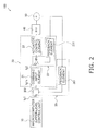
- FIG 2 is a control block diagram of the motor control device 100.
- the microcomputer 10 which is an upper-level control unit, sets an upper-level target value tg1, and inputs the upper-level target value tg1 through the intermediate control unit 30 (described further below) into the rotation speed control circuit 20, which is a lower-level control unit.
- the upper-level target value tg1 is a target rotation speed for the brushless DC motor 50.
- the rotation speed control circuit 20 which is the lower-level control unit, is connected to the microcomputer 10 and the gate driving circuit 26.
- the rotation speed control circuit 20 is a circuit for driving the brushless DC motor 50 on the basis of an operation command Vfg including a rotation speed command received from the microcomputer 10 via the intermediate control unit 30.
- the rotation speed control circuit 20, which is the lower-level control unit, includes a command input element 21, an actuator control element 22, and a tracking element 23.
- the command input element 21 receives an input of the upper-level target value tg1 via an adjustment unit 302 of the intermediate control unit 30 described further below.
- the adjustment unit 302 of the intermediate control unit 30 creates a pseudo upper-level target value tg1s obtained by increasing or decreasing the upper-level target value tg1, and inputs the pseudo upper-level target value tg1s into the command input element 21.
- the command input element 21 performs a process on the pseudo upper-level target value tg1s for adapting the pseudo upper-level target value tg1s for internal computation. In such an instance, due to a variation in the processing circuit, a value different from the pseudo upper-level target value tg1s is outputted. This value will be referred to as a lower-level target value tg2.
- the command input element 21 sets, at the input-side, the target rotation speed of the brushless DC motor 50 to 1000 rpm
- the variation in the processing circuit results in 950 rpm being outputted.
- the upper-level target value tg1 is 1000 rpm
- the lower-level target value tg2 is 950 rpm.
- the lower-level target value tg2 is subjected to a subtraction process with respect to the actual rotation speed received from the tracking element 23, and then inputted into the actuator control element 22.
- Possible variations in the processing circuit include those caused by a variation in properties of components constituting the command input element, a variation in the input value detection cycle, and/or a variation in the oscillation circuit for determining the control cycle for the rotation speed control circuit.
- the actuator control element 22 is a control unit for controlling the rotation speed of the brushless DC motor 50.
- the actuator control element 22 performs PI control on the rotation speed, and determines the voltage to be applied on the brushless DC motor 50.
- the rotation speed of the brushless DC motor 50 is controlled by changing the ON/OFF states of each of the transistors in the inverter 40.
- the actuator control element 22 inputs a command voltage Vpwm including the duties of the driving voltages SU, SV, and SW into the gate driving circuit 26 and thereby controls the gate driving circuit 26, and causes the gate driving circuit 26 to generate gate control voltages to be applied to the gates of the transistors so that the pulse-shaped driving voltages are outputted from the inverter 40 to the brushless DC motor 50.
- the tracking element 23 causes the actual rotation speed of the brushless DC motor 50 to track the lower-level target value tg2.
- the tracking element 23 includes a rotation speed computation unit 231 as a feedback element.
- the rotation speed computation unit 231 computationally obtains the present rotation speed of the brushless DC motor 50 using the rotor position detected by the rotor position detection sensor 54.
- the computation result is subjected to a subtraction process with respect to the lower-level target value tg2 and then inputted into the actuator control element 22.
- the tracking element 23 constitutes a closed loop for feeding back the actual rotation speed
- the rotation speed control circuit 20, which is the lower-level control unit has a closed loop for feeding back the actual rotation speed of the brushless DC motor 50.
- the intermediate control unit 30 causes the actual rotation speed of the brushless DC motor 50 to track the upper-level target value tg1.
- the intermediate control unit 30 includes a rotation speed computation unit 301 and an adjustment unit 302.
- the rotation speed computation unit 301 is a feedback element, and uses the rotor position detected by the rotor position detection sensor 54 to computationally obtain the present rotation speed of the brushless DC motor 50.
- the adjustment unit 302 increases or decreases the upper-level target value tg1 prior to the upper-level target value tg1 being inputted into the command input element 21.
- the post increase/decrease value i.e., the pseudo upper-level target value tg1s
- the intermediate control unit 30 constitutes a closed loop for feeding back the actual rotation speed of the brushless DC motor 50.
- the speed at which the intermediate control unit 30 causes the actual rotation speed of the brushless DC motor 50 to track the upper-level target value tg1 is set so as to be lower than the speed at which the tracking element 23 causes the actual rotation speed of the brushless DC motor 50 to track the lower-level target value tg2. Setting, e.g., an approximately tenfold difference between the tracking speeds makes it possible for the intermediate control unit 30 to absorb the variation in the command input element 21 after the lower-level control unit 20 has converged.
- the intermediate control unit 30 increases or decreases the upper-level target value tg1 and the variation in the command input element is absorbed. Therefore, the difference between the actual rotation speed and the rotation speed of the brushless DC motor 50 requested by the microcomputer 10 is reduced, and correct tracking of the upper-level target value tg1 becomes possible even when there is a variation in the command input element 21.
- the actuator control element 22 controls the rotation speed of the brushless DC motor 50 so as to converge to 950 rpm.
- the intermediate control unit 30 sets, e.g., a target rotation speed tg1s to 1050 rpm so as to be greater than tg1, whereby the output tg2 of the command input element 21 becomes 1000 rpm.
- the actuator control element 22 controls the rotation speed of the brushless DC motor 50 so as to converge to 1000 rpm, and the actual rotation speed coincides with the rotation speed of the brushless DC motor 50 requested by the microcomputer 10, which is the upper-level control unit. The fact that such a result can be obtained has been confirmed by experimentation performed by the applicant.
- FIG. 3 is a graph showing an example of the rotation speed response of a motor controlled by the motor control device 100.
- the horizontal axis represents time and the vertical axis represents the rotation speed.
- Each of the dotted curves represents the rotation speed response of a motor controlled by a conventional motor control device, and the solid curve represents the rotation speed response of a motor controlled by the motor control device of the present embodiment.
- the rotation speed of the motor controlled by the conventional motor control device converges, over time, so as to leave a given deviation, corresponding to the variation, from the target value.
- the rotation speed of the motor controlled by the motor control device of the present embodiment approaches, over time, the target value.
- scalability is also increased.
- realizing the intermediate control unit 30 as software on the microcomputer 10 makes it possible to respond to a change in specifications of the modularized circuit by changing a control constant on the software.
- the motor control device of the present invention makes it possible to cause the output of a brushless DC motor to track the command input from a microcomputer in an accurate manner, and is therefore useful not only for an indoor fan mounted on the indoor unit of a heat-pump-type air conditioner, but also for an outdoor fan mounted on the outdoor unit of an air conditioner or an outdoor fan mounted on a heat source unit of a heat-pump-type hot water supply device.
- Patent Literature 1 JP-A 58-99279
Landscapes
- Engineering & Computer Science (AREA)
- Power Engineering (AREA)
- Control Of Motors That Do Not Use Commutators (AREA)
- Control Of Electric Motors In General (AREA)
Abstract
Description
- The present invention relates to an actuator control device, and particularly to an actuator control device suitable for controlling of a motor.
- When an actuator such as a motor is controlled using an IC in which there is a large amount of variation in the command input circuit into which a command from, e.g., a microcomputer is inputted, instances occur in which the output of the actuator does not follow the command as required by the microcomputer.
- There is known, as a technique for solving this problem, e.g., in relation to a motor, a speed control device disclosed in the prior art in Patent Literature 1 (
JP-A 58-99279 - This Patent Literature also proposes an inexpensive speed control device in which the current value is estimated, whereby the current detector and the current adjuster are removed from the current minor control loop according to the prior art.
- However, the former presents an inconvenience in that, as pointed out in Patent Literature 1, the current detector and the current adjuster must be selected according to the current capacity of the motor. In the latter, in the current minor control loop, the estimated value of the current value is fed back. Therefore, an error with respect to the measured value is included, and it cannot be said that the motor output tracks the command input from an upper-level control unit in an accurate manner.
- The present invention addresses the problem of providing an actuator control device for causing the output of an actuator to track the command input from an upper-level control unit in an accurate manner, even when the actuator is controlled using an IC in which there is a large amount of variation in the command.
- An actuator control device according to a first aspect of the present invention comprises an upper-level control unit, a lower-level control unit, and an intermediate control unit. The upper-level control unit sets an upper-level target value of a predetermined control factor relating to driving an actuator. The lower-level control unit has a command input element, an actuator control element, and a tracking element. The command input element receives an input of the upper-level target value via the intermediate control unit, and outputs a lower-level target value of the predetermined control factor having a different value from the upper-level target value. The actuator control element receives an input of the lower-level target value and controls the actuator. The tracking element causes the actual value of the predetermined control factor in the actuator to track the lower-level target value. The intermediate control unit causes the actual value of the predetermined control factor in the actuator to track the upper-level target value. The upper-level target value is inputted into the command input element of the lower-level control unit via the intermediate control unit.
- In this actuator control device, the difference between the actual value and the target value of the predetermined control factor of the actuator required by the upper-level control unit is reduced.
- An actuator control device according to a second aspect of the present invention is the actuator control device according to the first aspect, wherein the intermediate control unit increases or decreases the upper-level target value inputted into the command input element in order to match the actual value of the predetermined control factor with the upper-level target value.
- In this actuator control device, the difference between the actual value and the target value of the predetermined control factor of the actuator required by the upper-level control unit is further reduced.
- An actuator control device according to a third aspect of the present invention is the actuator control device according to the first or second aspects, wherein the value inputted into the tracking element and the value inputted into the intermediate control unit are the same factor. In addition, each of the tracking element and the intermediate control unit constitutes a closed loop for feeding back the actual value of the predetermined control factor.
- In this actuator control device, since it is only necessary to monitor the same control factor, it is possible to reduce component cost and printed substrate size by, e.g., shared use of the detection circuit or other elements.
- An actuator control device according to a fourth aspect of the present invention is the actuator control device according to one of the first through third aspects, wherein the speed at which the intermediate control unit causes the actual value of the predetermined control factor to track the upper-level target value is lower than the speed at which the tracking element causes the actual value of the predetermined control factor to track the lower-level target value.
- In this actuator control device, the configuration is such that tracking of the upper-level target value is performed after the result of the previous control takes effect, therefore making it possible to prevent hunting (a phenomenon in which the rotation speed fluctuates up and down, causing a vibration) caused by the control for tracking the upper-level target value and the control for tracking the lower-level target value being performed simultaneously.
- An actuator control device according to a fifth aspect of the present invention is the actuator control device according to one of the first through fourth aspects, wherein the command input element, the actuator control element, and the tracking element in the lower-level control unit are modularized in a single package.
- In this actuator control device, the command input element, the actuator control element, and the tracking element are modularized in a single package, thereby making it possible to reduce the size and the cost of the lower-level control unit.
- An actuator control device according to a sixth aspect of the present invention is the actuator control device according to one of the first through fifth aspects, wherein the intermediate control unit is included in the upper-level control unit.
- In this actuator control device, in an example in which, e.g., the upper-level control unit, the lower-level control unit, and the intermediate control unit are mounted on a single printed substrate, a configuration in which the intermediate control unit is included in the upper-level control unit results in a decrease in the area occupied by the all of the mounted items on the printed substrate despite a moderate increase in the size of the upper-level control unit, making it possible to reduce the size of the printed substrate.
- An actuator control device according to a seventh aspect of the present invention is the actuator control device according to one of the first through sixth aspects, wherein the actuator is a motor, and the predetermined control factor is the rotation speed of the motor.
- In this actuator control device, in order to match the actual rotation speed of the motor with the upper-level target value, prior to the upper-level target value being inputted into the command input element, the intermediate control unit increases or decreases the upper-level target value, therefore reducing the difference between the actual rotation speed and the rotation speed of the motor requested by the upper-level control unit.
- In the actuator control device according to the first or second aspects of the present invention, the difference between the actual value and the target value of the predetermined control factor for the actuator requested by the upper-level control unit is reduced.
- In the actuator control device according to the third aspect of the present invention, since it is only necessary to monitor the same control factor, it is possible to reduce component cost and printed substrate size by, e.g., shared use of the detection circuit or other elements.
- In the actuator control device according to the fourth aspect of the present invention, the configuration is such that tracking of the upper-level target value is performed after the result of the previous control takes effect, therefore making it possible to prevent hunting.
- In the actuator control device according to the fifth aspect, the command input element, the actuator control element, and the tracking element are modularized in a single element, the actuator control element, and the tracking element are modularized in a single package, thereby making it possible to reduce the size and the cost of the lower-level control unit.
- In the actuator control device according to the sixth aspect, in an example in which, e.g., the upper-level control unit, the lower-level control unit, and the intermediate control unit are mounted on a single printed substrate, the area occupied by the all of the mounted items on the printed substrate decreases, making it possible to reduce the size of the printed substrate.
- In the actuator control device according to the seventh aspect, in order to match the actual rotation speed of the motor with the upper-level target value, prior to the upper-level target value being inputted into the command input element, the intermediate control unit increases or decreases the upper-level target value, therefore reducing the difference between the actual rotation speed and the rotation speed of the motor requested by the upper-level control unit.
-
-
FIG. 1 is a circuit diagram of a motor control device according to an embodiment of the present invention; -
FIG. 2 is a control block diagram of the motor control device; -
FIG. 3 is a graph showing the rotation speed response of a motor controlled by the motor control device; and -
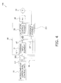
FIG. 4 is a control block diagram of a motor control device according to a first modification example. - An embodiment of the present invention will now be described with reference to the accompanying drawings. The following embodiment is a specific example of the present invention and is not intended to limit the technical scope of the present invention.
-
FIG. 1 is a circuit diagram of amotor control device 100 according to an embodiment of the present invention. InFIG. 1 , themotor control device 100 is an actuator control device for controlling the rotation of abrushless DC motor 50 using aninverter 40. Thebrushless DC motor 50 is used to drive anindoor fan 15 installed in an indoor unit of a heat-pump-type air conditioner. - The
brushless DC motor 50 is a three-phase brushless DC motor, and comprises astator 52, arotor 53, and a rotorposition detection sensor 54. Thestator 52 includes starconnected U-phase, V-phase, and W-phase driving coils Lu, Lv, and Lw. The ends of the driving coils Lu, Lv, and Lw are respectively connected to respective driving coil terminals TU, TV, and TW of U-phase, V-phase, and W-phase wires extending from theinverter 40. The other ends of the driving coils Lu, Lv, and Lw are connected to each other as a terminal TN. The rotation of therotor 53 causes the three-phase driving coils Lu, Lv, and Lw to generate an induced voltage corresponding to the rotation speed and the position of therotor 53. - The
rotor 53 includes a permanent magnet having a plurality of poles comprising an N-pole and an S-pole, and rotates about a rotary axis with respect to thestator 52. The rotation of therotor 53 is outputted, through an output shaft (not shown) disposed coaxially with respect to the rotation axis, to theindoor fan 15. - The rotor
position detection sensor 54 detects the rotation position of therotor 53. A Hall element is incorporated in thestator 52, and the rotorposition detection sensor 54 reacts to the Hall element and outputs a detection signal. - As shown in
FIG. 1 , themotor control device 100 comprises: a power supply unit configured as a DC power source from acommercial power source 91, arectification unit 17, and asmoothing capacitor 19; amicrocomputer 10 and a rotationspeed control circuit 20, agate driving circuit 26, anintermediate control unit 30, and aninverter 40. These elements are mounted, e.g., on a single printed substrate. - The
rectification unit 17 is configured as a bridge form by four diodes D1a, D1b, D2a, D2b. Specifically, the diodes D1a and D1b, and diodes D2a and D2b, are respectively connected in series to each other. The cathode terminals of the diodes D1a, D2a are both connected to a plus-side terminal of the smoothingcapacitor 19, and function as a positive-side output terminal of therectification unit 17. The anode terminals of the diodes D1b, D2b are both connected to the minus-side terminal of the smoothingcapacitor 19, and function as a negative-side output terminal of therectification unit 17. - The connection point between the diodes D1a and D1b is connected to one of the poles of the
commercial power source 91. The connection point between the diodes D2a and D2b is connected to the other pole of thecommercial power source 91. Therectification unit 17 rectifies the AC current outputted from thecommercial power source 91, generates a DC power supply, and supplies the DC power to the smoothingcapacitor 19. - One end of the smoothing
capacitor 19 is connected to the positive-side output terminal of therectification unit 17, and the other end of the smoothingcapacitor 19 is connected to the negative-side output terminal of therectification unit 17. The smoothingcapacitor 19 smoothes the voltage rectified by therectification unit 17. - The voltage after smoothing by the smoothing capacitor 19 (post-smoothing voltage) is applied to the
inverter 40 connected to the output side of the smoothingcapacitor 19. In other words, thecommercial power source 91, therectification unit 17, and the smoothingcapacitor 19 constitute a power supply unit for supplying power to theinverter 40. - Examples of the type of capacitor include an electrolytic capacitor, ceramic capacitor, and/or tantalum capacitor. However, in the present embodiment, an electrolytic capacitor is employed as the smoothing
capacitor 19. - The
inverter 40 is connected to the output side of the smoothingcapacitor 19. InFIG. 1 , theinverter 40 includes a plurality of insulated-gate bipolar transistors (IGBTs; hereafter referred to simply as transistors) Q3a, Q3b, Q4a, Q4b, Q5a, Q5b and a plurality of reflow diodes D3a, D3b, D4a, D4b, D5a, D5b. - The transistors Q3a and Q3b, transistors Q4a and Q4b, and transistors Q5a and Q5b are respectively connected in series to each other. Each of the diodes D3a to D5b is connected in parallel to a transistor Q3a to Q5b so that a collector terminal of the transistor and a cathode terminal of the diode are connected, and an emitter terminal of the transistor and an anode terminal of the diode are connected.
- The post-smoothing voltage from the smoothing
capacitor 19 being applied, and the transistors Q3a to Q5b being switched ON/OFF at a timing indicated by thegate driving circuit 26, cause theinverter 40 to generate driving voltages SU, SV, and SW for driving thebrushless DC motor 50. The driving voltages SU, SV, and SW are outputted from each of the connection points NU, NV, NW between the transistors Q3a and Q3b, Q4a and Q4b, and Q5a and Q5b to theblushless DC motor 50, respectively. - The
gate driving circuit 26 changes the ON/OFF state of the transistors Q3a to Q5b of theinverter 40 on the basis of a command Vpwm from the rotationspeed control circuit 20. Specifically, thegate driving circuit 26 generates gate control voltages Gu, Gx, Gv, Gy, Gw, and Gz applied on the gates of the transistors Q3a to Q5b so that pulse-shaped driving voltages SU, SV, and SW having a duty determined by the rotationspeed control circuit 20 are outputted from theinverter 40 to thebrushless DC motor 50. The generated gate control voltages Gu, Gx, Gv, Gy, Gw, and Gz are applied to the respective gate terminals of the transistors Q3a to Q5b. - The
inverter 40 in the present embodiment is a voltage-type inverter, but this is not provided by way of limitation. A matrix converter or a current-type inverter can also be used. - The
microcomputer 10 is connected to the rotationspeed control circuit 20. Themicrocomputer 10 is also connected to a system control unit (not shown) for performing overall control on the heat-pump-type air conditioner, and adapted to control the driving of thebrushless DC motor 50 according to the presence or absence of an abnormality in each device. Thus, themicrocomputer 10 functions as an upper-level control unit. A power supply separate from theinverter 40 is constantly supplied to themicrocomputer 10 irrespective of the driving state of thebrushless DC motor 50. -
FIG 2 is a control block diagram of themotor control device 100. InFIG. 2 , themicrocomputer 10, which is an upper-level control unit, sets an upper-level target value tg1, and inputs the upper-level target value tg1 through the intermediate control unit 30 (described further below) into the rotationspeed control circuit 20, which is a lower-level control unit. The upper-level target value tg1 is a target rotation speed for thebrushless DC motor 50. - The rotation
speed control circuit 20, which is the lower-level control unit, is connected to themicrocomputer 10 and thegate driving circuit 26. The rotationspeed control circuit 20 is a circuit for driving thebrushless DC motor 50 on the basis of an operation command Vfg including a rotation speed command received from themicrocomputer 10 via theintermediate control unit 30. - The rotation
speed control circuit 20, which is the lower-level control unit, includes acommand input element 21, anactuator control element 22, and atracking element 23. Thecommand input element 21 receives an input of the upper-level target value tg1 via anadjustment unit 302 of theintermediate control unit 30 described further below. In order to match the actual value being controlled with the upper-level target value tg1, prior to the upper-level target value tg1 being inputted into thecommand input element 21, theadjustment unit 302 of theintermediate control unit 30 creates a pseudo upper-level target value tg1s obtained by increasing or decreasing the upper-level target value tg1, and inputs the pseudo upper-level target value tg1s into thecommand input element 21. Thecommand input element 21 performs a process on the pseudo upper-level target value tg1s for adapting the pseudo upper-level target value tg1s for internal computation. In such an instance, due to a variation in the processing circuit, a value different from the pseudo upper-level target value tg1s is outputted. This value will be referred to as a lower-level target value tg2. - For example, even if the
command input element 21 sets, at the input-side, the target rotation speed of thebrushless DC motor 50 to 1000 rpm, the variation in the processing circuit results in 950 rpm being outputted. In other words, the upper-level target value tg1 is 1000 rpm, and the lower-level target value tg2 is 950 rpm. The lower-level target value tg2 is subjected to a subtraction process with respect to the actual rotation speed received from the trackingelement 23, and then inputted into theactuator control element 22. - Possible variations in the processing circuit include those caused by a variation in properties of components constituting the command input element, a variation in the input value detection cycle, and/or a variation in the oscillation circuit for determining the control cycle for the rotation speed control circuit.
- The
actuator control element 22 is a control unit for controlling the rotation speed of thebrushless DC motor 50. When the result of the subtraction process is inputted, theactuator control element 22 performs PI control on the rotation speed, and determines the voltage to be applied on thebrushless DC motor 50. Generally, the rotation speed of thebrushless DC motor 50 is controlled by changing the ON/OFF states of each of the transistors in theinverter 40. Theactuator control element 22 inputs a command voltage Vpwm including the duties of the driving voltages SU, SV, and SW into thegate driving circuit 26 and thereby controls thegate driving circuit 26, and causes thegate driving circuit 26 to generate gate control voltages to be applied to the gates of the transistors so that the pulse-shaped driving voltages are outputted from theinverter 40 to thebrushless DC motor 50. - The tracking
element 23 causes the actual rotation speed of thebrushless DC motor 50 to track the lower-level target value tg2. The trackingelement 23 includes a rotationspeed computation unit 231 as a feedback element. The rotationspeed computation unit 231 computationally obtains the present rotation speed of thebrushless DC motor 50 using the rotor position detected by the rotorposition detection sensor 54. - The computation result is subjected to a subtraction process with respect to the lower-level target value tg2 and then inputted into the
actuator control element 22. Thus, the trackingelement 23 constitutes a closed loop for feeding back the actual rotation speed, and the rotationspeed control circuit 20, which is the lower-level control unit, has a closed loop for feeding back the actual rotation speed of thebrushless DC motor 50. - The
intermediate control unit 30 causes the actual rotation speed of thebrushless DC motor 50 to track the upper-level target value tg1. Theintermediate control unit 30 includes a rotationspeed computation unit 301 and anadjustment unit 302. The rotationspeed computation unit 301 is a feedback element, and uses the rotor position detected by the rotorposition detection sensor 54 to computationally obtain the present rotation speed of thebrushless DC motor 50. In order to match the actual rotation speed of thebrushless DC motor 50 with the upper-level target value tg1, theadjustment unit 302 increases or decreases the upper-level target value tg1 prior to the upper-level target value tg1 being inputted into thecommand input element 21. The post increase/decrease value, i.e., the pseudo upper-level target value tg1s, is inputted into thecommand input element 21. Thus, theintermediate control unit 30 constitutes a closed loop for feeding back the actual rotation speed of thebrushless DC motor 50. - The speed at which the
intermediate control unit 30 causes the actual rotation speed of thebrushless DC motor 50 to track the upper-level target value tg1 is set so as to be lower than the speed at which thetracking element 23 causes the actual rotation speed of thebrushless DC motor 50 to track the lower-level target value tg2. Setting, e.g., an approximately tenfold difference between the tracking speeds makes it possible for theintermediate control unit 30 to absorb the variation in thecommand input element 21 after the lower-level control unit 20 has converged. - As described above, in order to match the actual rotation speed of the
brushless DC motor 50 with the upper-level target value tg1, prior to the upper-level target value tg1 being inputted into thecommand input element 21, theintermediate control unit 30 increases or decreases the upper-level target value tg1 and the variation in the command input element is absorbed. Therefore, the difference between the actual rotation speed and the rotation speed of thebrushless DC motor 50 requested by themicrocomputer 10 is reduced, and correct tracking of the upper-level target value tg1 becomes possible even when there is a variation in thecommand input element 21. - To describe this effect using specific values as an analogy, conventionally, even when the target rotation speed of the
brushless DC motor 50 is set to 1000 rpm, the variation in the processing circuit in thecommand input element 21 causes 950 rpm, which is smaller than the original target value, is outputted. Therefore, theactuator control element 22 controls the rotation speed of thebrushless DC motor 50 so as to converge to 950 rpm. However, in the present embodiment, in order to match the actual rotation speed of thebrushless DC motor 50 with the target rotation speed of 1000 rpm, theintermediate control unit 30 sets, e.g., a target rotation speed tg1s to 1050 rpm so as to be greater than tg1, whereby the output tg2 of thecommand input element 21 becomes 1000 rpm. Therefore, theactuator control element 22 controls the rotation speed of thebrushless DC motor 50 so as to converge to 1000 rpm, and the actual rotation speed coincides with the rotation speed of thebrushless DC motor 50 requested by themicrocomputer 10, which is the upper-level control unit. The fact that such a result can be obtained has been confirmed by experimentation performed by the applicant. -
FIG. 3 is a graph showing an example of the rotation speed response of a motor controlled by themotor control device 100. InFIG. 3 , the horizontal axis represents time and the vertical axis represents the rotation speed. Each of the dotted curves represents the rotation speed response of a motor controlled by a conventional motor control device, and the solid curve represents the rotation speed response of a motor controlled by the motor control device of the present embodiment. - As shown in
FIG. 3 , the rotation speed of the motor controlled by the conventional motor control device converges, over time, so as to leave a given deviation, corresponding to the variation, from the target value. In contrast, the rotation speed of the motor controlled by the motor control device of the present embodiment approaches, over time, the target value. -
- (3-1) In the
motor control device 100, themicrocomputer 10 sets the upper-level target rotation speed of thebrushless DC motor 50. Thecommand input element 21 of the rotationspeed control circuit 20 receives an input from the upper-level target rotation speed via theintermediate control unit 30, and outputs the lower-level target rotation speed having a different value to the upper-level target rotation speed. Theactuator control element 22 receives the input from the lower-level target rotation speed and controls thebrushless DC motor 50 by PI control. The trackingelement 23 causes the actual rotation speed of thebrushless DC motor 50 to track the lower-level target rotation speed. Theintermediate control unit 30 causes the actual rotation speed of thebrushless DC motor 50 to track the upper-level target rotation speed. In such an instance, in order to match the actual rotation speed of thebrushless DC motor 50 with the upper-level target rotation speed, prior to the upper-level target rotation speed being inputted into thecommand input element 21, theintermediate control unit 30 creates a pseudo upper-level target rotation speed obtained by increasing or decreasing the upper-level target rotation speed, and inputs the pseudo upper-level target rotation speed into thecommand input element 21. As a result, in themotor control device 100, the difference between the actual rotation speed and the target rotation speed of thebrushless DC motor 50 requested by themicrocomputer 10 is reduced. - (3-2) In the
motor control device 100, the speed at which theintermediate control unit 30 causes the actual rotation speed of thebrushless DC motor 50 to track the upper-level target rotation speed is set so as to be lower than the speed at which thetracking element 23 causes the actual rotation speed of thebrushless DC motor 50 to track the lower-level target rotation speed. In other words, the configuration is such that tracking of the upper-level target rotation speed is performed after the result of the previous control takes effect, therefore making it possible to prevent hunting (a phenomenon in which the rotation speed fluctuates up and down, causing a vibration). - (3-3) In the
motor control device 100, the rotationspeed control circuit 20 has a closed loop for feeding back the actual rotation speed of thebrushless DC motor 50. In addition, theintermediate control unit 30 constitutes a closed loop for feeding back the actual rotation speed of thebrushless DC motor 50. The values inputted into the rotationspeed control circuit 20 and theintermediate control unit 30 are the same factor, i.e., the actual rotation speed. -
- (4-1) First modification example
In the above embodiment, each of thetracking element 23 and theintermediate control unit 30 includes a feedback element as disclosed inFIG. 2 ; however, this is not provided by way of limitation. A description will now be given with reference toFIG. 4 .
FIG. 4 is a control block diagram of themotor control device 100 according to a first modification example. InFIG. 4 , the trackingelement 23 and theintermediate control unit 30 share the rotationspeed computation unit 231, which is a feedback element. It is thereby possible to reduce the size and the cost of themotor control device 100.
The control factor in theintermediate control unit 30 is, as with the trackingelement 23, the rotation speed of thebrushless DC motor 50. However, theadjustment unit 302 may perform an adjustment to a value that can be subjected to a subtraction process with respect to the upper-level target value tg1. In such an instance, the control factor will be the same but the values will be different. - (4-2) Second modification example
Thecommand input element 21, theactuator control element 22, and thetracking element 23 in the rotationspeed control circuit 20 may be modularized in a single package. It is thereby possible to reduce the size and the cost of the rotationspeed control circuit 20. - (4-3) Third modification example
Theintermediate control unit 30 may be included in themicrocomputer 10, which is the upper-level control unit. As a result, in an example in which, e.g., themicrocomputer 10, the rotationspeed control circuit 20, thegate driving circuit 26, theintermediate control unit 30, and theinverter 40 are mounted on a single printed substrate, theintermediate control unit 30 being included in themicrocomputer 10 and theintermediate control unit 30 being realized as software results in a decrease in the area occupied by all mounted items on the printed substrate, making it possible to reduce the size of the printed substrate. - In an instance in which a modularized circuit is used as in the second modification example, scalability is also increased. For example, realizing the
intermediate control unit 30 as software on themicrocomputer 10 makes it possible to respond to a change in specifications of the modularized circuit by changing a control constant on the software. - As described above, the motor control device of the present invention makes it possible to cause the output of a brushless DC motor to track the command input from a microcomputer in an accurate manner, and is therefore useful not only for an indoor fan mounted on the indoor unit of a heat-pump-type air conditioner, but also for an outdoor fan mounted on the outdoor unit of an air conditioner or an outdoor fan mounted on a heat source unit of a heat-pump-type hot water supply device.
-
- 10
- Microcomputer (upper-level control unit)
- 20
- Rotation speed control circuit (lower-level control unit)
- 21
- Command input element
- 22
- Actuator control element
- 23
- Tracking element
- 30
- Intermediate control unit
- 100
- Motor control device (actuator control device)
- [Patent Literature 1]
JP-A 58-99279
Claims (7)
- An actuator control device (100) comprising:an upper-level control unit (10) for setting an upper-level target value (tg1) of a predetermined control factor relating to driving an actuator;a lower-level control unit (20) havinga command input element (21) for receiving an input of the upper-level target value and outputting a lower-level target value (tg2) of the predetermined control factor having a different value from the upper-level target value,an actuator control element (22) for receiving an input of the lower-level target value and control the actuator, anda tracking element (23) for causing the actual value of the predetermined control factor in the actuator to track the lower-level target value; andan intermediate control unit (30) for causing the actual value of the predetermined control factor in the actuator to track the upper-level target value;the upper-level target value being inputted into the command input element of the lower-level control unit via the intermediate control unit.
- The actuator control device 100 according to claim 1, wherein
the intermediate control unit (30) increases or decreases the upper-level target value inputted into the command input element (21) in order to match the actual value of the predetermined control factor with the upper-level target value. - The actuator control device (100) according to claim 1 or 2, wherein
the value inputted into the tracking element (23) and the value inputted into the intermediate control unit (30) are the same factor, and
each of the tracking element (23) and the intermediate control unit (30) constitutes a closed loop for feeding back the actual value of the predetermined control factor. - The actuator control device (100) according to any of claims 1 through 3, wherein
the speed at which the intermediate control unit (30) causes the actual value of the predetermined control factor to track the upper-level target value is lower than the speed at which the tracking element (23) causes the actual value of the predetermined control factor to track the lower-level target value. - The actuator control device (100) according to any of claims 1 through 4, wherein
the command input element (21), the actuator control element (22), and the tracking element (23) in the lower-level control unit (20) are modularized in a single package. - The actuator control device (100) according to any of claims 1 through 5, wherein
the intermediate control unit (30) is included in the upper-level control unit (10). - The actuator control device (100) according to any of claims 1 through 6, wherein
the actuator is a motor, and
the predetermined control factor is the rotation speed of the motor.
Applications Claiming Priority (2)
| Application Number | Priority Date | Filing Date | Title |
|---|---|---|---|
| JP2011288954A JP5472285B2 (en) | 2011-12-28 | 2011-12-28 | Actuator control device |
| PCT/JP2012/083567 WO2013099900A1 (en) | 2011-12-28 | 2012-12-26 | Actuator control apparatus |
Publications (2)
| Publication Number | Publication Date |
|---|---|
| EP2797222A1 true EP2797222A1 (en) | 2014-10-29 |
| EP2797222A4 EP2797222A4 (en) | 2016-05-25 |
Family
ID=48697384
Family Applications (1)
| Application Number | Title | Priority Date | Filing Date |
|---|---|---|---|
| EP12861257.9A Withdrawn EP2797222A4 (en) | 2011-12-28 | 2012-12-26 | ACTUATOR CONTROL APPARATUS |
Country Status (8)
| Country | Link |
|---|---|
| US (1) | US9413277B2 (en) |
| EP (1) | EP2797222A4 (en) |
| JP (1) | JP5472285B2 (en) |
| KR (1) | KR101634471B1 (en) |
| CN (1) | CN104025451B (en) |
| AU (1) | AU2012361736B2 (en) |
| BR (1) | BR112014016014A8 (en) |
| WO (1) | WO2013099900A1 (en) |
Families Citing this family (4)
| Publication number | Priority date | Publication date | Assignee | Title |
|---|---|---|---|---|
| CN104836495A (en) * | 2015-05-22 | 2015-08-12 | 广东威灵电机制造有限公司 | Brushless DC motor and control device therefor |
| JP6909616B2 (en) | 2017-04-10 | 2021-07-28 | 株式会社日立製作所 | Manufacturing system and manufacturing method |
| JP2019110734A (en) * | 2017-12-20 | 2019-07-04 | 日本電産株式会社 | Motor device and motor system |
| JP2019161891A (en) * | 2018-03-14 | 2019-09-19 | 日本電産株式会社 | Motor control device and motor control method |
Family Cites Families (8)
| Publication number | Priority date | Publication date | Assignee | Title |
|---|---|---|---|---|
| JPS5899279A (en) * | 1981-12-04 | 1983-06-13 | Fuji Electric Co Ltd | Speed control device for dc motor |
| JP3937363B2 (en) | 1997-09-09 | 2007-06-27 | 東芝エレベータ株式会社 | Elevator speed control device |
| US7141946B2 (en) | 2003-09-15 | 2006-11-28 | Rockwell Automation Technologies, Inc. | Method and apparatus for providing optimal acceleration feedback |
| JP4335123B2 (en) * | 2004-11-26 | 2009-09-30 | ファナック株式会社 | Control device |
| JP4174543B2 (en) * | 2007-01-29 | 2008-11-05 | ファナック株式会社 | Servo motor control device |
| JP5152781B2 (en) * | 2007-09-20 | 2013-02-27 | ルネサスエレクトロニクス株式会社 | VCM driver and PWM amplifier |
| JP4715863B2 (en) * | 2008-05-01 | 2011-07-06 | ソニー株式会社 | Actuator control apparatus, actuator control method, actuator, robot apparatus, and computer program |
| US8277198B2 (en) * | 2008-11-13 | 2012-10-02 | Marvell International Ltd. | Fan motor control systems |
-
2011
- 2011-12-28 JP JP2011288954A patent/JP5472285B2/en not_active Expired - Fee Related
-
2012
- 2012-12-26 WO PCT/JP2012/083567 patent/WO2013099900A1/en not_active Ceased
- 2012-12-26 BR BR112014016014A patent/BR112014016014A8/en not_active IP Right Cessation
- 2012-12-26 US US14/368,492 patent/US9413277B2/en not_active Expired - Fee Related
- 2012-12-26 EP EP12861257.9A patent/EP2797222A4/en not_active Withdrawn
- 2012-12-26 CN CN201280064966.0A patent/CN104025451B/en not_active Expired - Fee Related
- 2012-12-26 AU AU2012361736A patent/AU2012361736B2/en not_active Ceased
- 2012-12-26 KR KR1020147020691A patent/KR101634471B1/en not_active Expired - Fee Related
Also Published As
| Publication number | Publication date |
|---|---|
| WO2013099900A1 (en) | 2013-07-04 |
| BR112014016014A8 (en) | 2017-07-04 |
| KR20140116433A (en) | 2014-10-02 |
| EP2797222A4 (en) | 2016-05-25 |
| US9413277B2 (en) | 2016-08-09 |
| JP5472285B2 (en) | 2014-04-16 |
| AU2012361736A1 (en) | 2014-08-14 |
| JP2013138578A (en) | 2013-07-11 |
| AU2012361736B2 (en) | 2015-05-28 |
| CN104025451A (en) | 2014-09-03 |
| BR112014016014A2 (en) | 2017-06-13 |
| KR101634471B1 (en) | 2016-06-28 |
| CN104025451B (en) | 2016-10-26 |
| US20140354198A1 (en) | 2014-12-04 |
Similar Documents
| Publication | Publication Date | Title |
|---|---|---|
| US9444377B2 (en) | Motor drive control device | |
| US8044620B2 (en) | Driving apparatus for multi-phase AC synchronous motor | |
| JP5539928B2 (en) | Motor drive device, fan control device and heat pump device using the same | |
| US9929682B2 (en) | Motor control device | |
| AU2012361736B2 (en) | Actuator control device | |
| CN104350674B (en) | Method and device for sensorless regulation of an externally excited synchronous machine | |
| CN104052341A (en) | Motor control device generating preload torque value | |
| JP7351196B2 (en) | Power converter and control method for power converter | |
| US20190199160A1 (en) | Motor | |
| JP4062074B2 (en) | Control method of three-phase brushless DC motor | |
| JP2010088200A (en) | Electric motor control device | |
| JP2016136820A (en) | Motor drive device | |
| JP2014171293A (en) | Device and method of controlling cooling fan | |
| CN115441808A (en) | Motor Generator Controls | |
| US20240088815A1 (en) | Control device | |
| JP2001086787A (en) | Control device for brushless motor | |
| CN111434025A (en) | Method for determining the rotor angle of an electric machine in a motor vehicle | |
| JP2018174670A (en) | Motor control device | |
| US10425023B2 (en) | Control device and control method of rotary electric machine | |
| JP6383884B1 (en) | Power generation control device, power generation control method, and power generation device | |
| CN117321904A (en) | Control device for rotating electrical machines | |
| JP2022080946A (en) | Control device for ac rotary machine |
Legal Events
| Date | Code | Title | Description |
|---|---|---|---|
| PUAI | Public reference made under article 153(3) epc to a published international application that has entered the european phase |
Free format text: ORIGINAL CODE: 0009012 |
|
| 17P | Request for examination filed |
Effective date: 20140721 |
|
| AK | Designated contracting states |
Kind code of ref document: A1 Designated state(s): AL AT BE BG CH CY CZ DE DK EE ES FI FR GB GR HR HU IE IS IT LI LT LU LV MC MK MT NL NO PL PT RO RS SE SI SK SM TR |
|
| DAX | Request for extension of the european patent (deleted) | ||
| RA4 | Supplementary search report drawn up and despatched (corrected) |
Effective date: 20160425 |
|
| RIC1 | Information provided on ipc code assigned before grant |
Ipc: H02P 6/06 20060101AFI20160419BHEP Ipc: H02P 23/22 20160101ALI20160419BHEP |
|
| STAA | Information on the status of an ep patent application or granted ep patent |
Free format text: STATUS: THE APPLICATION HAS BEEN WITHDRAWN |
|
| 18W | Application withdrawn |
Effective date: 20180123 |
|
| RIC1 | Information provided on ipc code assigned before grant |
Ipc: H02P 23/22 20160101ALI20160419BHEP Ipc: H02P 6/06 20060101AFI20160419BHEP |
|
| RIC1 | Information provided on ipc code assigned before grant |
Ipc: H02P 6/06 20060101AFI20160419BHEP Ipc: H02P 23/22 20160101ALI20160419BHEP |