EP2797205A2 - Matrix charger apparatus and charging method - Google Patents
Matrix charger apparatus and charging method Download PDFInfo
- Publication number
- EP2797205A2 EP2797205A2 EP20130189743 EP13189743A EP2797205A2 EP 2797205 A2 EP2797205 A2 EP 2797205A2 EP 20130189743 EP20130189743 EP 20130189743 EP 13189743 A EP13189743 A EP 13189743A EP 2797205 A2 EP2797205 A2 EP 2797205A2
- Authority
- EP
- European Patent Office
- Prior art keywords
- charger
- chargers
- charging
- battery modules
- battery module
- Prior art date
- Legal status (The legal status is an assumption and is not a legal conclusion. Google has not performed a legal analysis and makes no representation as to the accuracy of the status listed.)
- Granted
Links
Images


Classifications
-
- H—ELECTRICITY
- H02—GENERATION; CONVERSION OR DISTRIBUTION OF ELECTRIC POWER
- H02J—ELECTRIC POWER NETWORKS; CIRCUIT ARRANGEMENTS OR SYSTEMS FOR SUPPLYING OR DISTRIBUTING ELECTRIC POWER; SYSTEMS FOR STORING ELECTRIC ENERGY
- H02J7/00—Circuit arrangements for charging or discharging batteries or for supplying loads from batteries
- H02J7/50—Circuit arrangements for charging or discharging batteries or for supplying loads from batteries acting upon multiple batteries simultaneously or sequentially
- H02J7/52—Circuit arrangements for charging or discharging batteries or for supplying loads from batteries acting upon multiple batteries simultaneously or sequentially for charge balancing, e.g. equalisation of charge between batteries
- H02J7/56—Active balancing, e.g. using capacitor-based, inductor-based or DC-DC converters
-
- B—PERFORMING OPERATIONS; TRANSPORTING
- B60—VEHICLES IN GENERAL
- B60L—PROPULSION OF ELECTRICALLY-PROPELLED VEHICLES; SUPPLYING ELECTRIC POWER FOR AUXILIARY EQUIPMENT OF ELECTRICALLY-PROPELLED VEHICLES; ELECTRODYNAMIC BRAKE SYSTEMS FOR VEHICLES IN GENERAL; MAGNETIC SUSPENSION OR LEVITATION FOR VEHICLES; MONITORING OPERATING VARIABLES OF ELECTRICALLY-PROPELLED VEHICLES; ELECTRIC SAFETY DEVICES FOR ELECTRICALLY-PROPELLED VEHICLES
- B60L53/00—Methods of charging batteries, specially adapted for electric vehicles; Charging stations or on-board charging equipment therefor; Exchange of energy storage elements in electric vehicles
- B60L53/20—Methods of charging batteries, specially adapted for electric vehicles; Charging stations or on-board charging equipment therefor; Exchange of energy storage elements in electric vehicles characterised by converters located in the vehicle
- B60L53/22—Constructional details or arrangements of charging converters specially adapted for charging electric vehicles
-
- H—ELECTRICITY
- H02—GENERATION; CONVERSION OR DISTRIBUTION OF ELECTRIC POWER
- H02J—ELECTRIC POWER NETWORKS; CIRCUIT ARRANGEMENTS OR SYSTEMS FOR SUPPLYING OR DISTRIBUTING ELECTRIC POWER; SYSTEMS FOR STORING ELECTRIC ENERGY
- H02J7/00—Circuit arrangements for charging or discharging batteries or for supplying loads from batteries
- H02J7/14—Circuit arrangements for charging or discharging batteries or for supplying loads from batteries for charging batteries from dynamo-electric generators driven at varying speed, e.g. on vehicle
- H02J7/1423—Circuit arrangements for charging or discharging batteries or for supplying loads from batteries for charging batteries from dynamo-electric generators driven at varying speed, e.g. on vehicle with multiple batteries
-
- Y—GENERAL TAGGING OF NEW TECHNOLOGICAL DEVELOPMENTS; GENERAL TAGGING OF CROSS-SECTIONAL TECHNOLOGIES SPANNING OVER SEVERAL SECTIONS OF THE IPC; TECHNICAL SUBJECTS COVERED BY FORMER USPC CROSS-REFERENCE ART COLLECTIONS [XRACs] AND DIGESTS
- Y02—TECHNOLOGIES OR APPLICATIONS FOR MITIGATION OR ADAPTATION AGAINST CLIMATE CHANGE
- Y02T—CLIMATE CHANGE MITIGATION TECHNOLOGIES RELATED TO TRANSPORTATION
- Y02T10/00—Road transport of goods or passengers
- Y02T10/60—Other road transportation technologies with climate change mitigation effect
- Y02T10/70—Energy storage systems for electromobility, e.g. batteries
-
- Y—GENERAL TAGGING OF NEW TECHNOLOGICAL DEVELOPMENTS; GENERAL TAGGING OF CROSS-SECTIONAL TECHNOLOGIES SPANNING OVER SEVERAL SECTIONS OF THE IPC; TECHNICAL SUBJECTS COVERED BY FORMER USPC CROSS-REFERENCE ART COLLECTIONS [XRACs] AND DIGESTS
- Y02—TECHNOLOGIES OR APPLICATIONS FOR MITIGATION OR ADAPTATION AGAINST CLIMATE CHANGE
- Y02T—CLIMATE CHANGE MITIGATION TECHNOLOGIES RELATED TO TRANSPORTATION
- Y02T10/00—Road transport of goods or passengers
- Y02T10/60—Other road transportation technologies with climate change mitigation effect
- Y02T10/7072—Electromobility specific charging systems or methods for batteries, ultracapacitors, supercapacitors or double-layer capacitors
-
- Y—GENERAL TAGGING OF NEW TECHNOLOGICAL DEVELOPMENTS; GENERAL TAGGING OF CROSS-SECTIONAL TECHNOLOGIES SPANNING OVER SEVERAL SECTIONS OF THE IPC; TECHNICAL SUBJECTS COVERED BY FORMER USPC CROSS-REFERENCE ART COLLECTIONS [XRACs] AND DIGESTS
- Y02—TECHNOLOGIES OR APPLICATIONS FOR MITIGATION OR ADAPTATION AGAINST CLIMATE CHANGE
- Y02T—CLIMATE CHANGE MITIGATION TECHNOLOGIES RELATED TO TRANSPORTATION
- Y02T90/00—Enabling technologies or technologies with a potential or indirect contribution to GHG emissions mitigation
- Y02T90/10—Technologies relating to charging of electric vehicles
- Y02T90/12—Electric charging stations
-
- Y—GENERAL TAGGING OF NEW TECHNOLOGICAL DEVELOPMENTS; GENERAL TAGGING OF CROSS-SECTIONAL TECHNOLOGIES SPANNING OVER SEVERAL SECTIONS OF THE IPC; TECHNICAL SUBJECTS COVERED BY FORMER USPC CROSS-REFERENCE ART COLLECTIONS [XRACs] AND DIGESTS
- Y02—TECHNOLOGIES OR APPLICATIONS FOR MITIGATION OR ADAPTATION AGAINST CLIMATE CHANGE
- Y02T—CLIMATE CHANGE MITIGATION TECHNOLOGIES RELATED TO TRANSPORTATION
- Y02T90/00—Enabling technologies or technologies with a potential or indirect contribution to GHG emissions mitigation
- Y02T90/10—Technologies relating to charging of electric vehicles
- Y02T90/14—Plug-in electric vehicles
Definitions
- the technical field relates to a matrix charger apparatus and a charging method.
- the charger apparatus not only charges the battery module series but also equalizes the batteries.
- the conventional charger apparatus includes not only the charger but also a corresponding monitor/equalization circuit (adjustment logic) installed in each battery module of the battery module series to monitor/equalize the charging condition of every battery module and to control matching or equalization of the battery module series.
- the additional monitor/equalization circuit often increases the cost of the conventional charger apparatus; moreover, the cost of the charger is rather high due to the high charge voltage supply of the charger for charging the battery module series.
- the disclosure is directed to a charger apparatus and a charging method by using a plurality of chargers to simultaneously charge/discharge and equalize battery modules that are connected in series.
- An embodiment of the disclosure provides a charger apparatus that is applied to charge/discharge the battery module series.
- the battery module series comprises a plurality of battery modules connected in series.
- the charger apparatus comprises a plurality of chargers which are grouped at least into the first charger group and the second charger group, and these chargers comprise at least the first charger and the second charger.
- the first charger is grouped into the above-mentioned first charger group.
- the charging current output terminal of the first charger is coupled to the positive terminal of the i-th battery module of the battery modules, while the charging current input terminal of the first charger is coupled to a first node which is between the j-th battery module and the k-th battery module of the battery modules, wherein i, j, and k are integers, and j is between i and k.
- the second charger is grouped into the second charger group mentioned above.
- the charging current output terminal of the second charger is coupled to the second node which is between the i-th battery module and the j-th battery module, and the charging current input terminal of the second charger is coupled to the negative terminal of the k-th battery module.
- An embodiment of the disclosure provides a charging method.
- the charging method includes following steps.
- a plurality of chargers are grouped at least into the first charger group and the second charger group, wherein the first charger group comprises at least the first charger, while the second charger group comprises at least the second charger.
- the first charger group and the second charger group are coupled to the battery module series to charge/discharge the battery module series.
- the battery module series comprises a plurality of battery modules connected in series.
- the charging current output terminal of the first charger is coupled to the positive terminal of the i-th battery module of the battery modules.
- the charging current input terminal of the first charger is coupled to the first node which is between the j-th battery module and the k-th battery module of those battery modules, wherein i, j, and k are integers, and j is between i and k.
- the charging current output terminal of the second charger is coupled to the second node which is between the i-th battery module and the j-th battery module mentioned above, and the charging current input terminal of the second charger is coupled to the negative terminal of the k-th battery module.
- An embodiment of the disclosure provides a charging method.
- the charging method includes following steps.
- Each charger of a plurality of chargers connected to the battery module series separately selects a corresponding connection pattern from a plurality of connection patterns, wherein each battery module of a plurality of battery modules of the battery module series is charged/discharged by at least one of those chargers.
- the chargers are grouped at least into the first charger group and the second charger group, and the first charging combination of the first charger group is different from the second charging combination of the second charger group.
- the first charging combination indicates each battery module of those battery modules is charged by several chargers of the first charger group, while the second charging combination indicates each battery module of those battery modules is charged by several chargers of the second charger group.
- the charger apparatus and the charging method can provide a charging structure that charges/discharges serially-connected battery modules by means of the chargers and simultaneously completes the battery equalization. Therefore, the charger apparatus and the charging method described in the embodiments of the disclosure do not need any additional monitor/equalization circuit.
- FIG. 1 is a schematic block diagram of a circuit of a charger apparatus according to an embodiment of the disclosure.
- FIG. 3 is a schematic diagram illustrating all connection patterns that may be selected by a charger to connect a battery module series exemplarily having four battery modules.
- FIG. 4 is a schematic flow chart of a charging method according to an embodiment of the disclosure.
- FIG. 5 is a schematic block diagram of a circuit of a charger apparatus according to yet another embodiment of the disclosure.
- FIG. 6 is a schematic diagram illustrating experiment results of the charger apparatus shown in FIG. 5 according to an embodiment of the disclosure.
- FIG. 7 is a schematic block diagram of a circuit of a charger apparatus according to yet another embodiment of the disclosure.
- Coupled used in the full disclosure (including the claims) can refer to any direct or indirect connection means.
- first apparatus can be directly connected to the second apparatus, or the first apparatus can be indirectly connected to the second apparatus through another apparatus or a certain connection means.
- components / the elements / the steps in the drawings and the embodiments herein share the same or similar reference numerals. In different embodiments, the components / the elements / the steps having the same reference numerals or using the same wording may cross-reference to related descriptions.
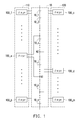
- FIG. 1 is a schematic block diagram of a circuit of a charger apparatus according to an embodiment of the disclosure.
- the charger apparatus shown in FIG. 1 can charge and discharge the battery module series 10.
- the battery module series 10 includes n battery modules 10_1, 10_2, ..., 10_i, ..., 10_j, ..., 10_k, ..., and 10_n connected in series, as shown in FIG. 1 .
- i, j, k, and n are integers
- i, j, and k are smaller than n
- j ranges between i and k.
- the battery modules 10_1 to 10_n can be a single battery cell (i.e., a battery cell monomer) or a battery cell group composed of a plurality of battery cells.
- the battery modules 10_1 to 10_n can have no battery monitor circuit, or each of the battery modules 10_1 to 10_n may individually contains a dedicated battery monitor circuit. If the battery modules 10_1 to 10_n each contain a dedicated battery monitor circuit, the battery monitor circuits can be operated independently of each other.
- the charging current output terminal and the charging current input terminal of the charger are coupled separately to the positive terminal (the anode) of the first battery module 10_1 and the negative terminal (the cathode) of the last battery module 10_n. Therefore, the charging voltage of the single charger may be set to be greater than or equal to the sum of the rated voltages of the n-th battery modules 10_1 to 10_n. Hence, the single charger supplying such high voltages may be costly.
- the charger apparatus shown in FIG. 1 has a plurality of chargers. Specifically, the charger apparatus shown in FIG. 1 includes m chargers 100_1, ..., 100_a, ..., 100_b, ..., 100_c, ..., 100_d, ..., and 100_m.
- a, b, c, d and m are integers, and a, b, c, and d are all smaller than m; these chargers 100_1 to 100_m can be divided into two or more charger groups.
- the chargers 100_1 to 100_m are grouped into the first charge group 110 and the second charger group 120.
- the chargers 100_1 ⁇ 100_a ⁇ 100_b are grouped into the first charge group 110, while the chargers 100_c ⁇ 100_d ⁇ 100_m are grouped into the second charger group 120.
- the actual number of chargers in the first charger group 110 and the second charger group 120 should not be limited to that depicted in FIG. 1 . For instance, if there are four chargers, the respective number of chargers in the first charger group 110 and the second charger group 120 may be one and three or two and two.
- the charging current output terminals and the charging current input terminals of the chargers 100_1 to 100_m are coupled separately to the corresponding battery modules of the battery modules 10_1 to 10_n.
- the charging current output terminal of the charger 100_a is coupled to the positive terminal (the anode) of the i-th battery module 10_i of the battery modules 10_1 to 10_n
- the charging current input terminal of the charger 100_a is coupled to the first node N1 which is between the j-th battery module 10_j and the k-th battery module 10_k of the battery modules 10_1 to 10_n.
- the charging current output terminal of the charger 100_d is coupled to the second node N2 which is between the i-th battery module 10_i and the j-th battery module 10_j , and the charging current input terminal of the charger 100_d is coupled to the negative terminal (the cathode) of the k-th battery module 10_k.
- the quantity m of the chargers 100_1 to 100_m is greater than or equal to the quantity n of the battery modules 10_1 to 10_n.
- the charging and discharging operations on the battery modules 10_1 to 10_n by the chargers 100_1 to 100_m are independent of each other.
- the chargers 100_1 to 100_m each apply a constant current (CC) method and / or a constant voltage (CV) method to charge and discharge the corresponding battery modules of the battery modules 10_1 to 10_n, while the way to implement the chargers 100_1 to 100_m is not limited in the embodiment.
- the arrangement relationship (the charging relationship) between the chargers 100_1 to 100_m and the battery modules 10_1 to 10_n can be represented by a configuration matrix A. Therefore, the configuration matrix A is an m*n matrix, where m is the quantity of chargers 100_1 to 100_m, and n is the quantity of battery modules 10_1 to 10_n.
- the x-th column of the configuration matrix A represents the battery modules charged and discharged by the x-th charger 100_x
- the y-th row of the configuration matrix A represents the chargers that charge and discharge the y-th battery module 10_y.
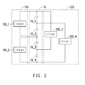
- FIG. 2 shows the arrangement relationship between the chargers 100_1 to 100_4 and the battery modules 10_1 to 10_4, and the charging voltage of the charger 100_1 can be set to be greater than or equal to the sum of the rated voltages of the two battery modules 10_1 and 10_2.
- the charging voltage of the charger 100_2 can be set to be greater than or equal to the sum of the rated voltages of the two battery modules 10_3 and 10_4.
- the charging voltage of the charger 100_3 can be set to be greater than or equal to the sum of three rated voltages of the battery modules 10_1, 10_2, and 10_3.
- the charging voltage of the charger 100_4 can be set to be greater than or equal to the sum of three rated voltages of the battery modules 10_2, 10_3, and 10_4.
- equation (2) "1" shown in the configuration matrix A in the first column and the first row represents the charging relationship between the first charger 100_1 and the first battery module 10_1; namely, the charging current of the first charger 100_1 can be directly or indirectly supplied to the first battery module 10_1.
- "0" indicates that there is no charging relationship between the first charger 100_1 and the fourth battery module 10_4.
- the other elements of the configuration matrix A can be accordingly deduced from the above.
- C 1 represents a capacitance value of the first battery module 10_1
- ⁇ V 1 represents the voltage change amount of the first battery module 10_1.
- the charging current output terminal and the charging current input terminal of each of the chargers 100_1 to 100_m is coupled separately to the corresponding battery module of the battery modules 10_1 to 10_n.
- the connection pattern of each charger coupled to the corresponding battery module series 10 includes: coupled to one battery module (n kinds of connection patterns), coupled to two battery modules (n-1 kinds of connection patterns), ..., and coupled to n battery modules (one kind of connection pattern).
- m kinds of the connection patterns may be selected from all connection patterns of the battery modules 10_1 to 10_n by the chargers 100_1 to 100_m mentioned above, wherein each of the battery modules 10_1 to 10_n can be directly or indirectly charged and discharged by at least one of the chargers.
- a PS 1 0 0 0 or 0 1 0 0 or 0 0 1 0 or 0 0 0 1 or 1 1 0 0 or 0 1 1 1 0 or 0 0 1 1 1 1 0 or 0 1 1 1 1 1 1 1 1 1 1 1 1 1 1 1 1 1 1 1 1 1 1 1 1 1 1 1 1 1 1 1 1 1 1 1 1
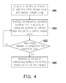
- FIG. 4 is a schematic flow chart of a charging method according to an embodiment of the disclosure.
- a plurality of the chargers of the charging apparatus can be at least grouped into the first charger group 110 and the second charger group 120.
- m chargers 100_1 to 100_m can be grouped into the first charger group 110 and the second charger group 120.
- each of the chargers 100_1 to 100_m respectively selects the corresponding connection pattern from a plurality of connection patterns to connect to the battery module series 10, wherein each battery module of the battery module series 10 can be charged and discharged by the chargers 100_1 to 100_m.
- the charging apparatus has four chargers 100_1 to 100_4, and the chargers can select four different kinds of the connected patterns from ten kinds of the connected patterns shown in FIG. 3 ; that is, four kinds of different matrices may be selected from ten kinds of the configurations matrices A PS shown in equation (6).
- the chargers 100_1 to 100_2 of the first charger group 110 select different corresponding connection patterns
- the chargers 100_3 to 100_4 of the second charger group 120 select different corresponding connection patterns.
- the connection patterns selected for these chargers 100_1 to 100_4 are different.
- the first charging combination indicates each of the battery modules 10_1 to 10_n is charged by some chargers of the first charger group 110
- the second charging combination indicates each of the battery modules 10_1 to 10_n is charged by some chargers of the second charger group 120.
- the configuration matrices A PS 0 0 1 1 and 1 1 1 0 are selected from the equation (6) in step S420 as the corresponding connection pattern of the chargers 100_1 and 100_2 of the first charger group 110
- the configuration matrices A PS 1 1 1 1 and 0 0 1 0 are selected in step S420 as the corresponding connection pattern of the chargers 100_3 and 100_4 of the second charger group 120.
- the first charger group 110 its corresponding first charging combination 0 1 0 1 1 1 1 1 0 indicates that the battery module 10_1 is charged/discharged by one charger, the battery module 10_2 is charged/discharged by one charger, the battery module 10_3 is charged/discharged by two chargers, and the battery charger module 10_4 is charged/discharged by one charger.
- step S420 when the connection patterns selected for the chargers 100_1 to 100_m appear to be "linearly independent of each other", the connection state can converges the battery voltage. For instance, in the battery module series 10 exemplarily having 4 battery modules 10_1 to 10_4, 1 0 0 0 , 0 1 0 0 , 0 0 1 0 , and 0 0 0 1 are selected by the chargers 100_1 to 100_4 as the connection patterns.
- step S430 If the determination result of the step S430 lies in that the connection patterns selected in step S420 do not comply with the connection rules, then the step S420 will once again be performed to select another combination of the connection patterns. If the determination result of the step S430 is that the connection patterns selected in the step S420 comply with the connection rules, then the connection relationships between the battery module series 10 and the chargers 100_1 to 100_m and the corresponding connection structures may be recognized/determined according to the connection patterns selected in the step S420 (step S440).
- the charging voltage of the charger 100_1 can be set to be greater than or equal to the sum of the rated voltages of the battery modules 10_1 and 10_2.
- the charging voltage of the charger 100_2 can be set to be greater than or equal to the sum of the rated voltages of the battery modules 10_3 and 10_4.
- the charging voltage of the charger 100_3 can be set to be greater than or equal to the sum of the rated voltages of the battery modules 10_2 and 10_3.
- the charging voltage of the charger 100_4 can be set to be greater than or equal to the sum of the rated voltage of the battery module 10_4.
- FIG. 5 shows the configuration relationship (the charging relationship) between the chargers 100_1 to 100_4 and the battery modules 10_1 to 10_4, and the configuration matrix A of the charging apparatus shown in FIG. 5 can be expressed as equation (7) as below.
- A 1 0 0 0 1 0 1 0 0 1 1 0 0 1 0 1 0 1 0 1 0 1 0 1 0 1 0 1 0 1 0 1 0 1
- the equation (7) shows that the rank of the configuration matrix A equals the quantity of the battery modules 10_1 to 10_4; that is, the configuration matrix A is a full rank matrix, so the voltage can converge during the charging/discharging operation of the charging apparatus shown in FIG. 5 . Therefore, the charging apparatus shown in FIG. 5 can simultaneously complete the charging operation and achieve battery equalization.
- additional resistors R1 and R2 are applied to simulate self-discharge of the battery modules 10_2 and 10_4.
- FIG. 6 is a schematic diagram illustrating experiment results of the charger apparatus shown in FIG. 5 according to an embodiment of the disclosure.
- the horizontal axis represents time (in units of minutes), and the ordinate axis indicates the voltage of the battery module (in units of volts).
- the charging voltage and the charging current of the chargers 100_1 to 100_3 are respectively set as 8V and 1A, while the charging voltage and the charging current of the charger 100_4 are 4V and 1A. From FIG. 6 , it can be learned that the voltages of the battery modules 10_1 to 10_4 can converge and can be equalized after the charging and discharging operations of the chargers 100_1 to 100_4, although the threshold voltages of the battery modules 10_1 to 10_4 shown in FIG. 5 are different from each other before charging, and the battery modules 10_2 and 10_4 may perform the self-discharging operation. Therefore, the charging apparatus shown in FIG. 5 can simultaneously complete the charging operation and achieve battery equalization.
- the circuit structure of the charging apparatus shown in FIG. 5 remains unchanged, but the charging voltage and the charging current of the charger 100_1 is set as 7.7V and 1A, the charging voltage and the charging current of the charger 100_2 is 8.1V and 1A, the charging voltage and the charging current of the charger 100_3 is 7.9V and 1A, and the charging voltage and the charging current of the charger 100_4 is 4.1V and 1A.
- the threshold voltages of the battery modules 10_1 to 10_4 shown in FIG. 5 are different from each other, and the battery modules 10_2 and 10_4 may perform the self-discharging operation.
- FIG. 1 , FIG. 2 , and FIG. 5 show the charging apparatus that is coupled to the corresponding battery module of the battery module series 10 in a dispersed and interleaved manner (e.g., like a matrix), so the charging apparatus can easily and efficiently perform the charging and discharging operation on the battery module series 10.
- the charging apparatus shown in FIG. 1 , FIG. 2 , and FIG. 5 is not required to be re-designed nor is required to be serially connected to a converter.
- the serially connected battery modules may be charged and discharged by the chargers, and battery equalization may be simultaneously achieved.
- the charging apparatus and the charging method do not require additional monitor/equalization circuit according to the embodiment.
- FIG. 7 is a schematic block diagram of a circuit of a charger apparatus according to yet another embodiment of the disclosure, and the embodiment shown in FIG. 7 and the embodiments shown in FIG. 1 , FIG. 2 , and FIG. 5 can be cross-referenced to one another.
- the configuration matrix A of the charging apparatus shown in FIG. 7 can be expressed as equation (7) below.
- the rank of the configuration matrix A equals the number of the battery modules 10_1 to 10_4 shown in equation (7), which indicates that the configuration matrix A is a full rank matrix.
- the charger 100_3 shown in FIG. 7 when the charger 100_3 shown in FIG. 7 is malfunctioned or disabled, the voltages of the remaining chargers 100_1, 100_2, 100_4, and 100_5, can converge during the charging and discharging operations. Therefore, the charging operations and battery equalization of the remaining chargers 100_1, 100_2, 100_4, and 100_5 shown in FIG. 7 can be completed simultaneously.
- the chargers 100_2, 100_3, 100_4, and 100_5 are selected to charge and discharge the battery modules 10_1 to 10_4, and the charger 100_1 is disabled.
- the configuration matrix A of the charging apparatus shown in FIG. 7 can be expressed as equation (9) below.
- the equation (9) shows that the rank of the configuration matrix A equals the number of the battery modules 10_1 to 10_4, which indicates that the configuration matrix A is a full rank matrix.
- the charging apparatus shown in FIG. 7 and characterized by fault tolerance can simultaneously perform the charging operation and achieve battery equalization.
- the charging apparatus depicted in FIG. 7 is coupled to the corresponding battery modules of the battery module series 10 in a dispersed and interlaced manner (e.g., a matrix); accordingly, the charging apparatus can easily and efficiently charge and discharge the battery module series 10, and thus the charging apparatus shown in FIG. 7 and the charging method described herein do not require any additional monitor/equalization circuit.
Landscapes
- Engineering & Computer Science (AREA)
- Power Engineering (AREA)
- Transportation (AREA)
- Mechanical Engineering (AREA)
- Charge And Discharge Circuits For Batteries Or The Like (AREA)
- Secondary Cells (AREA)
Abstract
Description
- The technical field relates to a matrix charger apparatus and a charging method.
- There are lots of electrical apparatuses supplied by batteries, such as handheld electronic devices, cell-driven vehicles, or other apparatuses with built-in batteries; in general, the batteries can serially connect battery modules to form at least one battery module series for supplying the voltage level required by the above-mentioned electrical apparatus. After the above-mentioned electrical apparatus consumes electricity supplied by the battery module series, the conventional charger apparatus charges the battery module series by using one charger; however, the difference in characteristics of different battery modules of the battery module series often causes charging and discharging difference between these battery modules, such as undercharge or overcharge.
- Therefore, the charger apparatus not only charges the battery module series but also equalizes the batteries. The conventional charger apparatus includes not only the charger but also a corresponding monitor/equalization circuit (adjustment logic) installed in each battery module of the battery module series to monitor/equalize the charging condition of every battery module and to control matching or equalization of the battery module series. The additional monitor/equalization circuit often increases the cost of the conventional charger apparatus; moreover, the cost of the charger is rather high due to the high charge voltage supply of the charger for charging the battery module series.
- Accordingly, the disclosure is directed to a charger apparatus and a charging method by using a plurality of chargers to simultaneously charge/discharge and equalize battery modules that are connected in series.
- An embodiment of the disclosure provides a charger apparatus that is applied to charge/discharge the battery module series. The battery module series comprises a plurality of battery modules connected in series. The charger apparatus comprises a plurality of chargers which are grouped at least into the first charger group and the second charger group, and these chargers comprise at least the first charger and the second charger. The first charger is grouped into the above-mentioned first charger group. The charging current output terminal of the first charger is coupled to the positive terminal of the i-th battery module of the battery modules, while the charging current input terminal of the first charger is coupled to a first node which is between the j-th battery module and the k-th battery module of the battery modules, wherein i, j, and k are integers, and j is between i and k. The second charger is grouped into the second charger group mentioned above. The charging current output terminal of the second charger is coupled to the second node which is between the i-th battery module and the j-th battery module, and the charging current input terminal of the second charger is coupled to the negative terminal of the k-th battery module.
- An embodiment of the disclosure provides a charging method. The charging method includes following steps. A plurality of chargers are grouped at least into the first charger group and the second charger group, wherein the first charger group comprises at least the first charger, while the second charger group comprises at least the second charger. The first charger group and the second charger group are coupled to the battery module series to charge/discharge the battery module series. The battery module series comprises a plurality of battery modules connected in series. The charging current output terminal of the first charger is coupled to the positive terminal of the i-th battery module of the battery modules. The charging current input terminal of the first charger is coupled to the first node which is between the j-th battery module and the k-th battery module of those battery modules, wherein i, j, and k are integers, and j is between i and k. The charging current output terminal of the second charger is coupled to the second node which is between the i-th battery module and the j-th battery module mentioned above, and the charging current input terminal of the second charger is coupled to the negative terminal of the k-th battery module.
- An embodiment of the disclosure provides a charging method. The charging method includes following steps. Each charger of a plurality of chargers connected to the battery module series separately selects a corresponding connection pattern from a plurality of connection patterns, wherein each battery module of a plurality of battery modules of the battery module series is charged/discharged by at least one of those chargers. The chargers are grouped at least into the first charger group and the second charger group, and the first charging combination of the first charger group is different from the second charging combination of the second charger group. The first charging combination indicates each battery module of those battery modules is charged by several chargers of the first charger group, while the second charging combination indicates each battery module of those battery modules is charged by several chargers of the second charger group.
- As described above, in the embodiments of the disclosure, the charger apparatus and the charging method can provide a charging structure that charges/discharges serially-connected battery modules by means of the chargers and simultaneously completes the battery equalization. Therefore, the charger apparatus and the charging method described in the embodiments of the disclosure do not need any additional monitor/equalization circuit.
- Several exemplary embodiments accompanied with figures are described in detail below to further describe the disclosure in details.
- The disclosure will become more fully understood from the detailed description given herein below for illustration only and thus does not limit the disclosure, wherein:
-
FIG. 1 is a schematic block diagram of a circuit of a charger apparatus according to an embodiment of the disclosure. -
FIG. 2 is a schematic block diagram of a circuit of a charger apparatus according to another embodiment of disclosure. -
FIG. 3 is a schematic diagram illustrating all connection patterns that may be selected by a charger to connect a battery module series exemplarily having four battery modules. -
FIG. 4 is a schematic flow chart of a charging method according to an embodiment of the disclosure. -
FIG. 5 is a schematic block diagram of a circuit of a charger apparatus according to yet another embodiment of the disclosure. -
FIG. 6 is a schematic diagram illustrating experiment results of the charger apparatus shown inFIG. 5 according to an embodiment of the disclosure. -
FIG. 7 is a schematic block diagram of a circuit of a charger apparatus according to yet another embodiment of the disclosure. - In the following detailed description, for purposes of explanation, numerous specific details are set forth in order to provide a thorough understanding of the disclosed embodiments. It will be apparent, however, that one or more embodiments may be practiced without these specific details. In other instances, well-known structures and devices are schematically shown in order to simplify the drawing.
- "Coupling" used in the full disclosure (including the claims) can refer to any direct or indirect connection means. For example, in the disclosure, if the first apparatus is coupled to the second apparatus, it should be interpreted that the first apparatus can be directly connected to the second apparatus, or the first apparatus can be indirectly connected to the second apparatus through another apparatus or a certain connection means. In addition, where possible, the components / the elements / the steps in the drawings and the embodiments herein share the same or similar reference numerals. In different embodiments, the components / the elements / the steps having the same reference numerals or using the same wording may cross-reference to related descriptions.
-
FIG. 1 is a schematic block diagram of a circuit of a charger apparatus according to an embodiment of the disclosure. The charger apparatus shown inFIG. 1 can charge and discharge thebattery module series 10. Thebattery module series 10 includes n battery modules 10_1, 10_2, ..., 10_i, ..., 10_j, ..., 10_k, ..., and 10_n connected in series, as shown inFIG. 1 . Here, i, j, k, and n are integers, i, j, and k are smaller than n, and j ranges between i and k. The battery modules 10_1 to 10_n can be a single battery cell (i.e., a battery cell monomer) or a battery cell group composed of a plurality of battery cells. In addition, the battery modules 10_1 to 10_n can have no battery monitor circuit, or each of the battery modules 10_1 to 10_n may individually contains a dedicated battery monitor circuit. If the battery modules 10_1 to 10_n each contain a dedicated battery monitor circuit, the battery monitor circuits can be operated independently of each other. - If the charger apparatus shown in
FIG. 1 is assumed to use one single charger, then the charging current output terminal and the charging current input terminal of the charger are coupled separately to the positive terminal (the anode) of the first battery module 10_1 and the negative terminal (the cathode) of the last battery module 10_n. Therefore, the charging voltage of the single charger may be set to be greater than or equal to the sum of the rated voltages of the n-th battery modules 10_1 to 10_n. Apparently, the single charger supplying such high voltages may be costly. - The charger apparatus shown in
FIG. 1 has a plurality of chargers. Specifically, the charger apparatus shown inFIG. 1 includes m chargers 100_1, ..., 100_a, ..., 100_b, ..., 100_c, ..., 100_d, ..., and 100_m. Here, a, b, c, d and m are integers, and a, b, c, and d are all smaller than m; these chargers 100_1 to 100_m can be divided into two or more charger groups. For example, in the embodiment, the chargers 100_1 to 100_m are grouped into thefirst charge group 110 and thesecond charger group 120. The chargers 100_1 ∼ 100_a ∼ 100_b are grouped into thefirst charge group 110, while the chargers 100_c ∼ 100_d ∼ 100_m are grouped into thesecond charger group 120. The actual number of chargers in thefirst charger group 110 and thesecond charger group 120 should not be limited to that depicted inFIG. 1 . For instance, if there are four chargers, the respective number of chargers in thefirst charger group 110 and thesecond charger group 120 may be one and three or two and two. - The charging current output terminals and the charging current input terminals of the chargers 100_1 to 100_m are coupled separately to the corresponding battery modules of the battery modules 10_1 to 10_n. For example, the charging current output terminal of the charger 100_a is coupled to the positive terminal (the anode) of the i-th battery module 10_i of the battery modules 10_1 to 10_n, the charging current input terminal of the charger 100_a is coupled to the first node N1 which is between the j-th battery module 10_j and the k-th battery module 10_k of the battery modules 10_1 to 10_n. The charging current output terminal of the charger 100_d is coupled to the second node N2 which is between the i-th battery module 10_i and the j-th battery module 10_j , and the charging current input terminal of the charger 100_d is coupled to the negative terminal (the cathode) of the k-th battery module 10_k.
- The quantity m of the chargers 100_1 to 100_m is greater than or equal to the quantity n of the battery modules 10_1 to 10_n. The charging and discharging operations on the battery modules 10_1 to 10_n by the chargers 100_1 to 100_m are independent of each other. The chargers 100_1 to 100_m each apply a constant current (CC) method and / or a constant voltage (CV) method to charge and discharge the corresponding battery modules of the battery modules 10_1 to 10_n, while the way to implement the chargers 100_1 to 100_m is not limited in the embodiment. For example, any one of the chargers 100_1 to 100_m can be a power supply unit, a bipolar power supply unit, a DC-DC convertor, an AC-DC convertor, a voltage regulator, or any other charging/discharging circuit. In some embodiments, the internal circuit structure of the chargers 100_1 to 100_m can be the same. In other embodiments, some or all of the internal circuit structures of the chargers 100_1 to 100_m can be different.
- The arrangement relationship (the charging relationship) between the chargers 100_1 to 100_m and the battery modules 10_1 to 10_n can be represented by a configuration matrix A. Therefore, the configuration matrix A is an m*n matrix, where m is the quantity of chargers 100_1 to 100_m, and n is the quantity of battery modules 10_1 to 10_n. Here, the x-th column of the configuration matrix A represents the battery modules charged and discharged by the x-th charger 100_x, and the y-th row of the configuration matrix A represents the chargers that charge and discharge the y-th battery module 10_y. If the configuration matrix A represents the charging relationship between the chargers 100_1 to 100_m and the battery modules 10_1 to 10_n, the configuration matrix A is a full rank matrix. For example, the configuration matrix A can be an identity matrix or any other full-rank matrix. The configuration matrix A satisfies the equation (1), where X is the instantaneous electric quantity vector of the chargers 100_1 to 100_m, and Y is the instantaneous voltage change amount vector of the battery modules 10_1 to 10_n. The examples of the matrix A and the vectors X and Y will be described in detail later.

-
FIG. 1 shows that the chargers 100_1 to 100_m of the charging apparatus can be connected to the battery modules 10_1 to 10_n dispersedly and interlacedly (i.e., in form of a matrix), and both the charging operation and battery equalization are simultaneously completed. Each charger manages its work without cooperating with the other chargers, and the charging apparatus depicted inFIG. 1 can be regulated intellectually due to its matrix structural design. - A four-series-and-one-parallel (4S1P) battery combination matrix charging structure is taken for example.
FIG. 2 is a schematic block diagram of a circuit of a charger apparatus according to another embodiment of disclosure. The embodiment shown inFIG. 2 and the embodiment shown inFIG. 1 can be cross-referenced. With reference toFIG. 2 , in this embodiment, the charging apparatus includes four chargers 100_1, 100_2, 100_3, and 100_4 (i.e., m = 4), and thebattery module series 10 comprises four battery modules 10_1, 10_2, 10_3, and 10_4 (i.e., n = 4) connected in series. The chargers 100_1 to 100_4 can be grouped into thefirst charger group 110 and thesecond charger group 120. Here, for example, the chargers 100_1 and 100_2 are grouped into thefirst group 110, and the chargers 100_3 and 100_4 are grouped into thesecond charger group 120. -
FIG. 2 shows the arrangement relationship between the chargers 100_1 to 100_4 and the battery modules 10_1 to 10_4, and the charging voltage of the charger 100_1 can be set to be greater than or equal to the sum of the rated voltages of the two battery modules 10_1 and 10_2. The charging voltage of the charger 100_2 can be set to be greater than or equal to the sum of the rated voltages of the two battery modules 10_3 and 10_4. The charging voltage of the charger 100_3 can be set to be greater than or equal to the sum of three rated voltages of the battery modules 10_1, 10_2, and 10_3. The charging voltage of the charger 100_4 can be set to be greater than or equal to the sum of three rated voltages of the battery modules 10_2, 10_3, and 10_4. The chargers 100_1 to 100_4 independently charge and discharge the battery modules 10_1 to 10_4 from each other without having to cooperate with other chargers. For example, the battery charger 100_1 can measure the voltage of the battery series (measuring the voltages of the battery modules 10_1 and 10_2). When the voltage of the battery series (the battery modules 10_1 and 10_2) is too low, the charger 100_1 can charge the battery series (the battery modules 10_1 and 10_2); when the voltage of the battery series (the battery modules 10_1 and 10_2) is too high, the charger 100_1 can discharge the battery series (the battery modules 10_1 and 10_2). The charging and discharging operations of the remaining chargers 100_2 to 100_4 can be performed accordingly. Finally, the voltage of the each battery modules 10_1 to 10_4 can reach the target voltage and can be equalized. -
FIG. 2 shows the configuration relationships (i.e., the charging relationship) between the chargers 100_1 to 100_4 and the battery modules 10_1 to 10_4, so that the configuration matrix A of the charging apparatus shown inFIG. 2 can be expressed as equation (2). The instantaneous electric quantity vector X of the chargers 100_1 to 100_4 can be expressed as equation (3), and the instantaneous voltage change vector Y of the battery modules 10_1 to 10_4 can be expressed as equation (4). Here, the matrix A and the vectors X and Y can be expressed as equation (5).


- In equation (2), "1" shown in the configuration matrix A in the first column and the first row represents the charging relationship between the first charger 100_1 and the first battery module 10_1; namely, the charging current of the first charger 100_1 can be directly or indirectly supplied to the first battery module 10_1. In the first column and the fourth row of the configuration matrix A shown in the equation (2), "0" indicates that there is no charging relationship between the first charger 100_1 and the fourth battery module 10_4. The other elements of the configuration matrix A can be accordingly deduced from the above.
- In the instantaneous electric quantity vector X of the chargers 100_1 to 100_4 shown in equation (3), I 1 represents the output value of the charging current of the first charger 100_1, and I 1 t 1 represents the output of the charging electric quantity of the first charger 100_1 during the time t 1. The other elements of the instantaneous electric quantity vector X can be deduced from the above accordingly.
- In the instantaneous voltage change amount vector Y of the battery modules 10_1 to 10_4 shown in equation (4), C 1 represents a capacitance value of the first battery module 10_1, and ΔV 1 represents the voltage change amount of the first battery module 10_1. The other elements of the instantaneous voltage change amount vector Y can be deduced from the above accordingly.
- In
FIG. 1 , the charging current output terminal and the charging current input terminal of each of the chargers 100_1 to 100_m is coupled separately to the corresponding battery module of the battery modules 10_1 to 10_n. The connection pattern of each charger coupled to the correspondingbattery module series 10 includes: coupled to one battery module (n kinds of connection patterns), coupled to two battery modules (n-1 kinds of connection patterns), ..., and coupled to n battery modules (one kind of connection pattern). Here, m kinds of the connection patterns may be selected from all connection patterns of the battery modules 10_1 to 10_n by the chargers 100_1 to 100_m mentioned above, wherein each of the battery modules 10_1 to 10_n can be directly or indirectly charged and discharged by at least one of the chargers. - The
battery module series 10 with four battery modules 10_1 to 10_4 is taken for example. In thebattery module series 10, one charger in total may select from ten kinds (4+3+2+1) of the connection patterns to connect thebattery module series 10.FIG. 3 is a schematic diagram illustrating all connection patterns that may be selected by the charger to connect a battery module series exemplarily having four battery modules. The configuration matrix APS showing the connection relationship between the charger and the four battery modules can be expressed as equation (6). The equation (6) shows ten kinds of the connection patterns representing the connection relationship between the charger and the batter module series, which may be referred to as that shown inFIG. 3 . The embodiment shown inFIG. 1 may also be deduced from the descriptions with respect toFIG. 3 .
-
FIG. 4 is a schematic flow chart of a charging method according to an embodiment of the disclosure. In step S410, a plurality of the chargers of the charging apparatus can be at least grouped into thefirst charger group 110 and thesecond charger group 120. For example, m chargers 100_1 to 100_m can be grouped into thefirst charger group 110 and thesecond charger group 120. In step S420, each of the chargers 100_1 to 100_m respectively selects the corresponding connection pattern from a plurality of connection patterns to connect to thebattery module series 10, wherein each battery module of thebattery module series 10 can be charged and discharged by the chargers 100_1 to 100_m. For example, assuming that the charging apparatus has four chargers 100_1 to 100_4, and the chargers can select four different kinds of the connected patterns from ten kinds of the connected patterns shown inFIG. 3 ; that is, four kinds of different matrices may be selected from ten kinds of the configurations matrices APS shown in equation (6). In this embodiment, the chargers 100_1 to 100_2 of thefirst charger group 110 select different corresponding connection patterns, and the chargers 100_3 to 100_4 of thesecond charger group 120 select different corresponding connection patterns. In other embodiments, the connection patterns selected for these chargers 100_1 to 100_4 are different. The relationship between the chargers 100_1 to 100_4 and the battery modules can be a "linearly independent" relationship (e.g.,


cover 
- In equation (6), four out of ten kinds of the configuration matrices APS are selected to form the configuration matrix A, where the rank of the configuration matrix A is equal to the quantity n of the battery modules 10_1 to 10_n, and the voltage can converge for sure during the charging and discharging operation. When the chargers 100_1 to 100_m are mutually linearly independent; that is, the configuration matrix A is a full rank matrix, the charging apparatus can simultaneously perform the charging operation and achieve battery equalization. As exemplarily shown in
FIG. 2 , four out of ten kinds of different configuration matrices APS shown in equation (6) are selected, and the selected four configuration matrices APS are


FIG. 2 can charge and equalize batteries simultaneously during the charging and discharging operation. - With reference to
FIG. 4 , in step S430, the connection pattern selected in step S420 may be examined to determine if it meets connection rules. One or more inspection methods may be conducted in step S430. For example, in some embodiments, whether the configuration matrix A is a full rank matrix or not may be determined in step S430; in another embodiment, the first charging combination of thefirst charger group 110 and the second charging combination of thesecond charger group 120 may be examined in step S430. Here, "the first charging combination" is obtained by each charger of thefirst charger group 110 respectively selecting the corresponding connection pattern from a plurality of connection patterns to connect to thebattery module series 10; "the second charging combination" is obtained by each charger of thesecond charger group 120 respectively selecting the corresponding connection pattern from a plurality of connection patterns to connect to thebattery module series 10. The first charging combination indicates each of the battery modules 10_1 to 10_n is charged by some chargers of thefirst charger group 110, and the second charging combination indicates each of the battery modules 10_1 to 10_n is charged by some chargers of thesecond charger group 120. For example, in thebattery module series 10 exemplarily having four battery modules 10_1 to 10_4, the configuration matrices APS

first charger group 110, and the configuration matrices APS

second charger group 120. As for thefirst charger group 110, its corresponding first chargingcombination 
second charger group 120, its correspondingsecond charging combination 
connection patterns 

first charger group 110 and theconnection patterns 

second charger group 120 selected in step S420 do not comply with the connection rules. - In another embodiment, whether the connection patterns selected by the chargers 100_1 to 100_m in step S420 are repeated/are the same may be examined in step S430. For example, if the connection patterns selected by the chargers 100_1 and 100_2 in step S420 are both

- In step S420, when the connection patterns selected for the chargers 100_1 to 100_m appear to be "linearly independent of each other", the connection state can converges the battery voltage. For instance, in the
battery module series 10 exemplarily having 4 battery modules 10_1 to 10_4,

- When the connection patterns selected by the chargers 100_1 to 100_m appear to be mutually "covered" and "connected in a cross-lapped manner" in step S420, step S430 determine/check whether connection pattern of each of the chargers can be substituted with other connection patterns, and if yes, such condition should be avoided. For example, if


- If the determination result of the step S430 lies in that the connection patterns selected in step S420 do not comply with the connection rules, then the step S420 will once again be performed to select another combination of the connection patterns. If the determination result of the step S430 is that the connection patterns selected in the step S420 comply with the connection rules, then the connection relationships between the
battery module series 10 and the chargers 100_1 to 100_m and the corresponding connection structures may be recognized/determined according to the connection patterns selected in the step S420 (step S440). -
FIG. 5 is a schematic block diagram of a circuit of a charger apparatus according to yet another embodiment of the disclosure. The embodiments shown inFIG. 5 ,FIG. 1 , andFIG. 2 may be cross-referenced to one another. As shown inFIG. 5 , in the embodiment, the charging apparatus includes four chargers 100_1, 100_2, 100_3, and 100_4 (i.e., m = 4), and thebattery module series 10 includes four serially connected battery modules 10_1, 10_2, 10_3, and 10_4 (i.e., n = 4).FIG. 5 shows the configuration relationships between the chargers 100_1 to 100_4 and the battery modules 10_1 to 10_4. The charging voltage of the charger 100_1 can be set to be greater than or equal to the sum of the rated voltages of the battery modules 10_1 and 10_2. The charging voltage of the charger 100_2 can be set to be greater than or equal to the sum of the rated voltages of the battery modules 10_3 and 10_4. The charging voltage of the charger 100_3 can be set to be greater than or equal to the sum of the rated voltages of the battery modules 10_2 and 10_3. The charging voltage of the charger 100_4 can be set to be greater than or equal to the sum of the rated voltage of the battery module 10_4. By determining the charging voltages respectively output by the chargers 100_1 to 100_4, the fully-charged voltages of different battery modules may be set, which is elaborated hereinafter. -
FIG. 5 shows the configuration relationship (the charging relationship) between the chargers 100_1 to 100_4 and the battery modules 10_1 to 10_4, and the configuration matrix A of the charging apparatus shown inFIG. 5 can be expressed as equation (7) as below.
- The equation (7) shows that the rank of the configuration matrix A equals the quantity of the battery modules 10_1 to 10_4; that is, the configuration matrix A is a full rank matrix, so the voltage can converge during the charging/discharging operation of the charging apparatus shown in
FIG. 5 . Therefore, the charging apparatus shown inFIG. 5 can simultaneously complete the charging operation and achieve battery equalization. - In order to verify the charging apparatus shown in
FIG. 5 , additional resistors R1 and R2 are applied to simulate self-discharge of the battery modules 10_2 and 10_4. Here, the electricity of the battery modules 10_2 and 10_4 is assumed to be 2Ah. If the battery module 10_4 self-discharges 2Ah to half of the electricity in seven days, the self-discharge current is (2Ah * 0.5) / (24h * 7) = 5.95mA. If the rated voltage of the battery modules 10_2 and 10_4 is assumed to be 3.7V, then the self-discharge resistance of the resistor R2 for simulation is 3.7V / (5.95mA) = 620Ω. If the battery module 10_2 self-discharges 2Ah to one fourth the power in seven days, the resistance of the resistor R2 is 1240Ω. -
FIG. 6 is a schematic diagram illustrating experiment results of the charger apparatus shown inFIG. 5 according to an embodiment of the disclosure. InFIG. 6 , the horizontal axis represents time (in units of minutes), and the ordinate axis indicates the voltage of the battery module (in units of volts). The charging voltage and the charging current of the chargers 100_1 to 100_3 are respectively set as 8V and 1A, while the charging voltage and the charging current of the charger 100_4 are 4V and 1A. FromFIG. 6 , it can be learned that the voltages of the battery modules 10_1 to 10_4 can converge and can be equalized after the charging and discharging operations of the chargers 100_1 to 100_4, although the threshold voltages of the battery modules 10_1 to 10_4 shown inFIG. 5 are different from each other before charging, and the battery modules 10_2 and 10_4 may perform the self-discharging operation. Therefore, the charging apparatus shown inFIG. 5 can simultaneously complete the charging operation and achieve battery equalization. - In another embodiment, the circuit structure of the charging apparatus shown in
FIG. 5 remains unchanged, but the charging voltage and the charging current of the charger 100_1 is set as 7.7V and 1A, the charging voltage and the charging current of the charger 100_2 is 8.1V and 1A, the charging voltage and the charging current of the charger 100_3 is 7.9V and 1A, and the charging voltage and the charging current of the charger 100_4 is 4.1V and 1A. Before charging, the threshold voltages of the battery modules 10_1 to 10_4 shown inFIG. 5 are different from each other, and the battery modules 10_2 and 10_4 may perform the self-discharging operation. However, after the charging and discharging operations of the chargers 100_1 to 100_4, the voltage of the battery module 10_1 can converge to 3.8V, the voltage of the battery module 10_2 can converge to 3.9V, the voltage of the battery module 10_3 can converge to 4.0V, and the voltage of the battery module 10_4 can converge to 4.1V. Therefore, the charging apparatus shown inFIG. 5 can complete the charging operation; at the same time, different battery modules may be set to have different fully-charged voltages. - As described above,
FIG. 1 ,FIG. 2 , andFIG. 5 show the charging apparatus that is coupled to the corresponding battery module of thebattery module series 10 in a dispersed and interleaved manner (e.g., like a matrix), so the charging apparatus can easily and efficiently perform the charging and discharging operation on thebattery module series 10. In the scenario of different voltages and different currents of the charging station, the charging apparatus shown inFIG. 1 ,FIG. 2 , andFIG. 5 is not required to be re-designed nor is required to be serially connected to a converter. According to the charging apparatus and the charging method described herein, the serially connected battery modules may be charged and discharged by the chargers, and battery equalization may be simultaneously achieved. Thus, the charging apparatus and the charging method do not require additional monitor/equalization circuit according to the embodiment. - In particular, the quantity m of the chargers 100_1 to 100_m can be greater than or equal to the quantity n of the battery modules 10_1 to 10_n. Under the condition that the quantity m of the chargers is greater than the quantity n of the battery modules, the charging apparatus shown in
FIG. 1 can be fault tolerant. For example, n battery modules can be connected to the (n+1) chargers, wherein n chargers selected from the (n+1) chargers can charge and discharge n battery modules, and the remaining charger may serve as a spare charger (not performing the charging and discharging operation). - For example,
FIG. 7 is a schematic block diagram of a circuit of a charger apparatus according to yet another embodiment of the disclosure, and the embodiment shown inFIG. 7 and the embodiments shown inFIG. 1 ,FIG. 2 , andFIG. 5 can be cross-referenced to one another. As shown inFIG. 7 , in this embodiment, the charging apparatus includes five chargers 100_1, 100_2, 100_3, 100_4, and 100_5 (i.e., m = 5), and thebattery module series 10 includes four serially connected battery modules 10_1 , 10_2, 10_3, and 10_4 (i.e., n = 4).FIG. 7 shows the configuration relationships (the charging relationships) between the chargers 100_1 to 100_5 and the battery modules 10_1 to 10_4, and the configuration matrix A' of the charging apparatus shown inFIG. 7 can be expressed as equation (8) as below.
- In the embodiment, four out of five chargers 100_1 to 100_5 are selected to charge and discharge four battery modules 10_1 to 10_4, and the remaining charger serves as a spare charger (not performing the charging and discharging operation). For example, the chargers 100_1, 100_2, 100_4, and 100_5 are selected to charge and discharge the battery modules 10_1 to 10_4, and the charger 100_3 is disabled. In this case, the configuration matrix A of the charging apparatus shown in
FIG. 7 can be expressed as equation (7) below. According to equation (1), equation (3), equation (4), and equation (7), the voltage change amount of the battery module 10_1 is


FIG. 7 is malfunctioned or disabled, the voltages of the remaining chargers 100_1, 100_2, 100_4, and 100_5, can converge during the charging and discharging operations. Therefore, the charging operations and battery equalization of the remaining chargers 100_1, 100_2, 100_4, and 100_5 shown inFIG. 7 can be completed simultaneously. - In another example, the chargers 100_2, 100_3, 100_4, and 100_5 are selected to charge and discharge the battery modules 10_1 to 10_4, and the charger 100_1 is disabled. Here, the configuration matrix A of the charging apparatus shown in
FIG. 7 can be expressed as equation (9) below. According to equation (1), equation (3), equation (4), and equation (9), the voltage change amount of the battery module 10_1 is


FIG. 7 is malfunctioned or disabled, the voltages of the remaining battery chargers 100_2 to 100_5 can converge during the charging and discharging operations, and the charging operations and the battery equalization of the remaining chargers 100_2 to 100_5 shown inFIG. 7 can be simultaneously completed.
- Therefore, the charging apparatus shown in
FIG. 7 and characterized by fault tolerance can simultaneously perform the charging operation and achieve battery equalization. The charging apparatus depicted inFIG. 7 is coupled to the corresponding battery modules of thebattery module series 10 in a dispersed and interlaced manner (e.g., a matrix); accordingly, the charging apparatus can easily and efficiently charge and discharge thebattery module series 10, and thus the charging apparatus shown inFIG. 7 and the charging method described herein do not require any additional monitor/equalization circuit.
Claims (34)
- A charger apparatus for charging and discharging a battery module series (10), the battery module series (10) comprising a plurality of battery modules (10_1, 10_2, 10_3, 10_4, 10_i, 10_j, 10_k or 10_n) mutually connected in series, the charger apparatus comprising a plurality of chargers (100_1, 100_2, 100_3, 100_4, 100_5, 100_a, 100_b, 100_c, 100_d or 100_m), the chargers (100_1, 100_2, 100_3, 100_4, 100_5, 100_a, 100_b, 100_c, 100_d or 100_m) being at least grouped into a first charger group (110) and a second charger group (120), and the chargers (100_1, 100_2, 100_3, 100_4, 100_5, 100_a, 100_b, 100_c, 100_d or 100_m) comprising:a first charger (100_1, 100_2, 100_5, 100_a or 100_b) grouped into the first charger group (110), wherein a charging current output terminal of the first charger (100_1, 100_2, 100_5, 100_a or 100_b) is coupled to a positive terminal of a i-th battery module (10_i) of the battery modules (10_1, 10_2, 10_3, 10_4, 10_i, 10_j, 10_k or 10_n), and a charging current input terminal of the first charger (100_1, 100_2, 100_5, 100_a or 100_b) is coupled to a first node (N1) which is between a j-th battery module (10_j) and a k-th battery module (10_k) of the battery modules (10_1, 10_2, 10_3, 10_4, 10_i, 10_j, 10_k or 10_n), wherein i, j, and k are integers, and j is between i and k; anda second charger (100_3, 100_4, 100_5, 100_c, 100_d or 100_m) grouped into the second charger group (120), wherein a charging current output terminal of the second charger (100_3, 100_4, 100_5, 100_c, 100_d or 100_m) is coupled to a second node (N2) which is between the i-th battery module (10_i) and the j-th battery module (10_j) of the battery modules (10_1, 10_2, 10_3, 10_4, 10_i, 10_j, 10_k or 10_n), and a charging current input terminal of the second charger (100_3, 100_4, 100_5, 100_c, 100_d or 100_m) is coupled to a negative terminal of the k-th battery module (10_k).
- The charger apparatus as claimed in claim 1, wherein the quantity of the chargers (100_1, 100_2, 100_3, 100_4, 100_5, 100_a, 100_b, 100_c, 100_d or 100_m) is greater than or equal to the quantity of the battery modules (10_1, 10_2, 10_3, 10_4, 10_i, 10_j, 10_k or 10_n) of the battery module series (10).
- The charger apparatus as claimed in claim 1, wherein if a configuration matrix A represents a charging relationship between the chargers (100_1, 100_2, 100_3, 100_4, 100_5, 100_a, 100_b, 100_c, 100_d or 100_m) and the battery modules (10_1, 10_2, 10_3, 10_4, 10_i, 10_j, 10_k or 10_n), the configuration matrix A is not an identity matrix.
- The charger apparatus as claimed in claim 1, wherein if a configuration matrix A represents a charging relationship between the chargers (100_1, 100_2, 100_3, 100_4, 100_5, 100_a, 100_b, 100_c, 100_d or 100_m) and the battery modules (10_1, 10_2, 10_3, 10_4, 10_i, 10_j, 10_k or 10_n), the configuration matrix A is a full rank matrix.
- The charger apparatus as claimed in claim 1, wherein if a configuration matrix A represents a charging relationship between the chargers (100_1, 100_2, 100_3, 100_4, 100_5, 100_a, 100_b, 100_c, 100_d or 100_m) and the battery modules (10_1, 10_2, 10_3, 10_4, 10_i, 10_j, 10_k or 10_n), the configuration matrix A satisfies an equation AX = Y, wherein X is an instantaneous electric quantity vector of the chargers (100_1, 100_2, 100_3, 100_4, 100_5, 100_a, 100_b, 100_c, 100_d or 100_m), and Y is an instantaneous voltage change amount vector of the battery modules (10_1, 10_2, 10_3, 10_4, 10_i, 10_j, 10_k or 10_n).
- The charger apparatus as claimed in claim 5, wherein the configuration matrix A is an m*n matrix, m is the quantity of the chargers (100_1, 100_2, 100_3, 100_4, 100_5, 100_a, 100_b, 100_c, 100_d or 100_m), and n is the quantity of the battery modules (10_1, 10_2, 10_3, 10_4, 10_i, 10_j, 10_k or 10_n).
- The charger apparatus as claimed in claim 1, wherein charging and discharging operations conducted by the chargers (100_1, 100_2, 100_3, 100_4, 100_5, 100_a, 100_b, 100_c, 100_d or 100_m) are independent of each other.
- The charger apparatus as claimed in claim 1, wherein each of the chargers (100_1, 100_2, 100_3, 100_4, 100_5, 100_a, 100_b, 100_c, 100_d or 100_m) charges and discharges the corresponding battery module of the battery modules (10_1, 10_2, 10_3, 10_4, 10_i, 10_j, 10_k or 10_n) with constant current or constant voltage.
- The charger apparatus as claimed in claim 1, wherein fully-charged voltages of the different battery modules (10_1, 10_2, 10_3, 10_4, 10_i, 10_j, 10_k or 10_n) are set by determining respective charging voltages of the chargers (100_1, 100_2, 100_3, 100_4, 100_5, 100_a, 100_b, 100_c, 100_d or 100_m).
- The charger apparatus as claimed in claim 1, wherein each of the chargers (100_1, 100_2, 100_3, 100_4, 100_5, 100_a, 100_b, 100_c, 100_d or 100_m) respectively selects a corresponding connection pattern from a plurality of connection patterns to connect to the battery module series (10), and each of the battery modules (10_1, 10_2, 10_3, 10_4, 10_i, 10_j, 10_k or 10_n) is charged and discharged by at least one of the chargers (100_1, 100_2, 100_3, 100_4, 100_5, 100_a, 100_b, 100_c, 100_d or 100_m).
- The charger apparatus as claimed in claim 10, wherein the chargers of the first charger group (110) select the corresponding connection patterns different from each other, and the chargers of the second charger group (120) select the corresponding connection patterns different from each other.
- The charger apparatus as claimed in claim 10, wherein a first charging combination of the first charger group (110) is different from a second charging combination of the second charger group (120), wherein the first charging combination is formed by each of the chargers of the first charger group (110) respectively selecting the corresponding connection pattern from the connection patterns to connect to the batter module series, and the second charging combination is formed by each of the chargers of the second charger group (120) respectively selecting the corresponding connection pattern from the connection patterns to connect to the batter module series.
- A charging method comprising:grouping a plurality of chargers (100_1, 100_2, 100_3, 100_4, 100_5, 100_a, 100_b, 100_c, 100_d or 100_m) at least into a first charger group (110) and a second charger group (120), wherein the first charger group (110) at least comprises a first charger (100_1, 100_2, 100_5, 100_a or 100_b), and the second charger group (120) at least comprises a second charger (100_3, 100_4, 100_5, 100_c, 100_d or 100_m); andcoupling the first charger group (110) and the second charger group (120) to a battery module series (10) to charge and discharge the battery module series (10),wherein the battery module series (10) comprises a plurality of battery modules (10_1, 10_2, 10_3, 10_4, 10_i, 10_j, 10_k or 10_n) mutually connected in series, wherein a charging current output terminal of the first charger (100_1, 100_2, 100_5, 100_a or 100_b) is coupled to a positive terminal of a i-th battery module (10_i) of the battery modules (10_1, 10_2, 10_3, 10_4, 10_i, 10_j, 10_k or 10_n), and a charging current input terminal of the first charger (100_1, 100_2, 100_5, 100_a or 100_b) is coupled to a first node (N1) which is between aj-th battery module (10_j) and a k-th battery module (10_k) of the battery modules (10_1, 10_2, 10_3, 10_4, 10_i, 10_j, 10_k or 10_n), wherein i, j, and k are integers, and j is between i and k,wherein a charging current input terminal of the second charger (100_3, 100_4, 100_5, 100_c, 100_d or 100_m) is coupled to a second node (N2) which is between the i-th battery module (10_i) and the j-th battery module (10_j) of the battery modules (10_1, 10_2, 10_3, 10_4, 10_i, 10_j, 10_k or 10_n), and a charging current input terminal of the second charger (100_3, 100_4, 100_5, 100_c, 100_d or 100_m) is coupled to a negative terminal of the k-th battery module (10_k).
- The charging method as claimed in claim 13, further comprising:setting the quantity of the chargers (100_1, 100_2, 100_3, 100_4, 100_5, 100_a, 100_b, 100_c, 100_d or 100_m) to be greater than or equal to the quantity of the battery modules (10_1, 10_2, 10_3, 10_4, 10_i, 10_j, 10_k or 10_n) of the battery module series (10).
- The charging method as claimed in claim 13, further comprising:representing the charging relationship between the chargers (100_1, 100_2, 100_3, 100_4, 100_5, 100_a, 100_b, 100_c, 100_d or 100_m) and the battery modules (10_1, 10_2, 10_3, 10_4, 10_i, 10_j, 10_k or 10_n) by a configuration matrix A, wherein the configuration matrix A is not an identity matrix.
- The charging method as claimed in claim 13, further comprising:representing a charging relationship between the chargers (100_1, 100_2, 100_3, 100_4, 100_5, 100_a, 100_b, 100_c, 100_d or 100_m) and the battery modules (10_1, 10_2, 10_3, 10_4, 10_i, 10_j, 10_k or 10_n) by a configuration matrix A; and making the configuration matrix A a full rank matrix.
- The charging method as claimed in claim 13, further comprising:representing a charging relationship between the chargers (100_1, 100_2, 100_3, 100_4, 100_5, 100_a, 100_b, 100_c, 100_d or 100_m) and the battery modules (10_1, 10_2, 10_3, 10_4, 10_i, 10_j, 10_k or 10_n) by a configuration matrix A; andmaking the configuration matrix A satisfy an equation AX = Y, wherein X is an instantaneous electric quantity vector of the chargers (100_1, 100_2, 100_3, 100_4, 100_5, 100_a, 100_b, 100_c, 100_d or 100_m), while Y is an instantaneous voltage change amount vector of the battery modules (10_1, 10_2, 10_3, 10_4, 10_i, 10_j, 10_k or 10_n).
- The charging method as claimed in claim 17, wherein the configuration matrix A is an m*n matrix, wherein m is the quantity of the chargers (100_1, 100_2, 100_3, 100_4, 100_5, 100_a, 100_b, 100_c, 100_d or 100_m), while n is the quantity of the battery modules (10_1, 10_2, 10_3, 10_4, 10_i, 10_j, 10_k or 10_n).
- The charging method as claimed in claim 13, wherein the charging and discharging operations of the chargers (100_1, 100_2, 100_3, 100_4, 100_5, 100_a, 100_b, 100_c, 100_d or 100_m) are independent of each other.
- The charging method as claimed in claim 13, wherein each of the chargers (100_1, 100_2, 100_3, 100_4, 100_5, 100_a, 100_b, 100_c, 100_d or 100_m) charges and discharges the corresponding battery module of the battery modules (10_1, 10_2, 10_3, 10_4, 10_i, 10_j, 10_k or 10_n) with constant current or constant voltage.
- The charging method as claimed in claim 13, further comprising:respectively setting fully-charged voltages of the different battery modules (10_1, 10_2, 10_3, 10_4, 10_i, 10_j, 10_k or 10_n) by determining respective charging voltages of the chargers (100_1, 100_2, 100_3, 100_4, 100_5, 100_a, 100_b, 100_c, 100_d or 100_m).
- The charging method as claimed in claim 13, wherein the step of coupling the first charger group (110) and the second charger group (120) to the battery module series (10) comprising:respectively selecting a corresponding connection pattern from a plurality of connection patterns for each of the chargers (100_1, 100_2, 100_3, 100_4, 100_5, 100_a, 100_b, 100_c, 100_d or 100_m) to connect to the battery module series (10), wherein each of the battery modules (10_1, 10_2, 10_3, 10_4, 10_i, 10_j, 10_k or 10_n) is charged and discharged by at least one of the chargers (100_1, 100_2, 100_3, 100_4, 100_5, 100_a, 100_b, 100_c, 100_d or 100_m).
- The charging method as claimed in claim 22, wherein the chargers of the first charger group (110) select the corresponding connection patterns different from each other, and the chargers of the second charger group (120) select the corresponding connection patterns different from each other.
- The charging method as claimed in claim 22, wherein a first charging combination of the first charger group (110) is different from a second charging combination of the second charger group (120), wherein the first charging combination is formed by each of the chargers of the first charger group (110) respectively selecting the corresponding connection pattern from the connection patterns to connect to the batter module series, and the second charging combination is formed by each of the chargers of the second charger group (120) respectively selecting the corresponding connection pattern from the connection patterns to connect to the batter module series.
- A charging method comprising:respectively selecting a corresponding connection pattern from a plurality of connection patterns for each charger of a plurality of chargers (100_1, 100_2, 100_3, 100_4, 100_5, 100_a, 100_b, 100_c, 100_d or 100_m) to connect to a battery module series (10), wherein each battery module of a plurality of battery modules (10_1, 10_2, 10_3, 10_4, 10_i, 10_j, 10_k or 10_n) of the battery module series (10) is charged and discharged by at least one of the chargers (100_1, 100_2, 100_3, 100_4, 100_5, 100_a, 100_b, 100_c, 100_d or 100_m); andgrouping the chargers (100_1, 100_2, 100_3, 100_4, 100_5, 100_a, 100_b, 100_c, 100_d or 100_m) at least into a first charger group (110) and a second charger group (120), wherein a first charging combination of the first charger group (110) is different from a second charging combination of the second charger group (120), the first charging combination is formed by each of the chargers of the first charger group (110) respectively selecting the corresponding connection pattern from the connection patterns to connect to the batter module series, and the second charging combination is formed by each of the chargers of the second charger group (120) respectively selecting the corresponding connection pattern from the connection patterns to connect to the batter module series.
- The charging method as claimed in claim 25, wherein the chargers of the first charger group (110) select the corresponding connection patterns different from each other, and the chargers of the second charger group (120) select the corresponding connection patterns different from each other.
- The charging method as claimed in claim 25, further comprising:setting the quantity of the chargers (100_1, 100_2, 100_3, 100_4, 100_5, 100_a, 100_b, 100_c, 100_d or 100_m) to be greater than or equal to the quantity of the battery modules (10_1, 10_2, 10_3, 10_4, 10_i, 10_j, 10_k or 10_n) of the battery module series (10).
- The charging method as claimed in claim 25, further comprising:representing a charging relationship between the chargers (100_1, 100_2, 100_3, 100_4, 100_5, 100_a, 100_b, 100_c, 100_d or 100_m) and the battery modules (10_1, 10_2, 10_3, 10_4, 10_i, 10_j, 10_k or 10_n) by a configuration matrix A, and making the configuration matrix A not an identity matrix.
- The charging method as claimed in claim 25, further comprising:representing a charging relationship between the chargers (100_1, 100_2, 100_3, 100_4, 100_5, 100_a, 100_b, 100_c, 100_d or 100_m) and the battery modules (10_1, 10_2, 10_3, 10_4, 10_i, 10_j, 10_k or 10_n) by a configuration matrix A; and making the configuration matrix A a full rank matrix.
- The charging method as claimed in claim 25, further comprising:representing a charging relationship between the chargers (100_1, 100_2, 100_3, 100_4, 100_5, 100_a, 100_b, 100_c, 100_d or 100_m) and the battery modules (10_1, 10_2, 10_3, 10_4, 10_i, 10_j, 10_k or 10_n) by a configuration matrix A; andmaking the configuration matrix A satisfy an equation AX = Y , wherein X is an instantaneous electric quantity vector of the chargers (100_1, 100_2, 100_3, 100_4, 100_5, 100_a, 100_b, 100_c, 100_d or 100_m), and Y is an instantaneous voltage change amount vector of the battery modules (10_1, 10_2, 10_3, 10_4, 10_i, 10_j, 10_k or 10_n).
- The charging method as claimed in claim 30, wherein the configuration matrix A is an m*n matrix, m is the quantity of the chargers (100_1, 100_2, 100_3, 100_4, 100_5, 100_a, 100_b, 100_c, 100_d or 100_m), and n is the quantity of the battery modules (10_1, 10_2, 10_3, 10_4, 10_i, 10_j, 10_k or 10_n).
- The charging method as claimed in claim 25, wherein the charging and discharging operations of the chargers (100_1, 100_2, 100_3, 100_4, 100_5, 100_a, 100_b, 100_c, 100_d or 100_m) are independent of each other.
- The charging method as claimed in claim 25, wherein each of the chargers (100_1, 100_2, 100_3, 100_4, 100_5, 100_a, 100_b, 100_c, 100_d or 100_m) charges and discharges the corresponding battery module of the battery modules (10_1, 10_2, 10_3, 10_4, 10_i, 10_j, 10_k or 10_n) with constant current or constant voltage.
- The charging method as claimed in claim 25, further comprising:respectively setting fully-charged voltages of the different battery modules (10_1, 10_2, 10_3, 10_4, 10_i, 10_j, 10_k or 10_n) by determining respective charging voltages of the chargers (100_1, 100_2, 100_3, 100_4, 100_5, 100_a, 100_b, 100_c, 100_d or 100_m).
Applications Claiming Priority (2)
| Application Number | Priority Date | Filing Date | Title |
|---|---|---|---|
| US201361815732P | 2013-04-25 | 2013-04-25 | |
| TW102125447A TWI502849B (en) | 2013-04-25 | 2013-07-16 | Matrix charger apparatus and charging method |
Publications (3)
| Publication Number | Publication Date |
|---|---|
| EP2797205A2 true EP2797205A2 (en) | 2014-10-29 |
| EP2797205A3 EP2797205A3 (en) | 2016-04-20 |
| EP2797205B1 EP2797205B1 (en) | 2020-03-18 |
Family
ID=49385190
Family Applications (1)
| Application Number | Title | Priority Date | Filing Date |
|---|---|---|---|
| EP13189743.1A Active EP2797205B1 (en) | 2013-04-25 | 2013-10-22 | Matrix charger apparatus and charging method |
Country Status (3)
| Country | Link |
|---|---|
| US (1) | US9466991B2 (en) |
| EP (1) | EP2797205B1 (en) |
| CN (1) | CN104124726B (en) |
Families Citing this family (10)
| Publication number | Priority date | Publication date | Assignee | Title |
|---|---|---|---|---|
| KR101470735B1 (en) * | 2013-05-15 | 2014-12-08 | 주식회사 엘지씨엔에스 | Apparatus and Method with an active balancing control circuit and an active balancing algorithm for charging and discharging the series connected secondary batteries |
| TWI568122B (en) | 2015-11-09 | 2017-01-21 | 財團法人工業技術研究院 | Battery system and its control method |
| TWI618330B (en) | 2016-10-28 | 2018-03-11 | 財團法人工業技術研究院 | Electronic device, battery module and charging and discharging method |
| TWI649939B (en) | 2017-07-07 | 2019-02-01 | 財團法人工業技術研究院 | Power supply device operation method, power supply device and power supply device management system |
| TWI657639B (en) | 2017-12-04 | 2019-04-21 | Industrial Technology Research Institute | Battery discharge process determination method and system |
| TWI649573B (en) | 2017-12-04 | 2019-02-01 | 財團法人工業技術研究院 | Method and system for detecting short circuit impedance in battery |
| TWI666848B (en) * | 2018-09-12 | 2019-07-21 | 財團法人工業技術研究院 | Fire control device for power storage system and operating method thereof |
| KR102747640B1 (en) * | 2018-11-07 | 2024-12-31 | 삼성전자주식회사 | Charger integrated circuit for charging battery device and electronic device including the same |
| US11349317B2 (en) * | 2018-11-07 | 2022-05-31 | Samsung Electronics Co., Ltd. | Charger integrated circuit for charging battery device and electronic device including the charger integrated circuit |
| CN116581852B (en) * | 2023-07-12 | 2023-09-22 | 钰泰半导体股份有限公司 | Multi-string lithium battery pack charging circuit and method based on buck charging circuit |
Family Cites Families (24)
| Publication number | Priority date | Publication date | Assignee | Title |
|---|---|---|---|---|
| US5821733A (en) | 1994-02-22 | 1998-10-13 | Packard Bell Nec | Multiple cell and serially connected rechargeable batteries and charging system |
| JPH0833219A (en) | 1994-07-18 | 1996-02-02 | Integuran Kk | Charger for series battery |
| TW421608B (en) * | 1996-11-12 | 2001-02-11 | Mitsubishi Gas Chemical Co | Method for drying resin-used electronic parts |
| US6377024B1 (en) | 2001-03-23 | 2002-04-23 | The Boeing Company | Method and system for charge equalization of lithium-ion batteries |
| US6943529B2 (en) | 2001-12-16 | 2005-09-13 | Zinc Matrix Power, Inc. | Battery charging system |
| JP3867581B2 (en) * | 2002-01-17 | 2007-01-10 | 松下電器産業株式会社 | Assembled battery system |
| US6771045B1 (en) | 2002-09-05 | 2004-08-03 | Ise Corporation | Systems and methods for battery charging and equalization |
| US20050269988A1 (en) | 2004-06-04 | 2005-12-08 | Maxwell Technologies, Inc. | Voltage balancing circuit for multi-cell modules |
| TWM289925U (en) | 2005-11-09 | 2006-04-21 | Sino American Electronic Co Lt | Smart-type battery charger with equalizer circuit |
| JP5285322B2 (en) * | 2008-04-16 | 2013-09-11 | パナソニック株式会社 | Voltage equalizing device, charging device, battery assembly, and charging system |
| KR101077154B1 (en) * | 2008-04-22 | 2011-10-27 | 한국과학기술원 | Two-Stage Charge Equalization Method and Apparatus for Series-Connected Battery String |
| JP5015073B2 (en) | 2008-06-20 | 2012-08-29 | 株式会社竹内製作所 | Charging system |
| KR101093597B1 (en) * | 2009-01-30 | 2011-12-15 | 한국과학기술원 | Automatic Charge Uniformity Device Using Constant Voltage Source |
| US8541980B2 (en) * | 2009-05-22 | 2013-09-24 | Intersil Americas LLC | System and method for cell balancing and charging |
| US8148942B2 (en) | 2009-11-05 | 2012-04-03 | O2Micro International Limited | Charging systems with cell balancing functions |
| CN102823104B (en) | 2010-02-05 | 2016-05-11 | 法国原子能源和替代能源委员会 | Charge equalization system for batteries |
| JP4848038B2 (en) | 2010-02-26 | 2011-12-28 | 幸男 高橋 | Charger and charger |
| US8564246B2 (en) | 2010-03-30 | 2013-10-22 | Grrreen, Inc. | Battery charging system and method |
| US8598840B2 (en) | 2010-04-15 | 2013-12-03 | Launchpoint Energy And Power Llc | Fault-tolerant battery management system, circuits and methods |
| EP2666228B1 (en) | 2011-01-22 | 2022-08-31 | Alpha Technologies Services, Inc. | Charge equalization systems and methods |
| TWM421608U (en) * | 2011-09-21 | 2012-01-21 | Green Solution Tech Co Ltd | Battery balancing controller, battery apparatus and battery module case for applying the same |
| CN102522602A (en) | 2011-12-02 | 2012-06-27 | 苏州冠硕新能源有限公司 | Method for actively balancing plurality of battery units in series connection with each other |
| CN202872396U (en) * | 2012-08-29 | 2013-04-10 | 华南理工大学 | Charge and discharge equalization circuit for series battery based on inductance energy storage |
| CN103066665A (en) * | 2013-01-18 | 2013-04-24 | 同济大学 | Active balancing circuit of power Li-ion battery module and balancing method thereof |
-
2013
- 2013-09-02 CN CN201310392236.XA patent/CN104124726B/en active Active
- 2013-10-09 US US14/049,236 patent/US9466991B2/en active Active
- 2013-10-22 EP EP13189743.1A patent/EP2797205B1/en active Active
Non-Patent Citations (1)
| Title |
|---|
| None |
Also Published As
| Publication number | Publication date |
|---|---|
| EP2797205A3 (en) | 2016-04-20 |
| US9466991B2 (en) | 2016-10-11 |
| CN104124726A (en) | 2014-10-29 |
| EP2797205B1 (en) | 2020-03-18 |
| US20140320067A1 (en) | 2014-10-30 |
| CN104124726B (en) | 2016-08-31 |
Similar Documents
| Publication | Publication Date | Title |
|---|---|---|
| US9466991B2 (en) | Matrix charger apparatus and charging method | |
| KR102120797B1 (en) | Battery charging-discharging apparatus and method | |
| Baronti et al. | Investigation of series-parallel connections of multi-module batteries for electrified vehicles | |
| Brandl et al. | Batteries and battery management systems for electric vehicles | |
| Wang et al. | A LiFePO4 battery pack capacity estimation approach considering in-parallel cell safety in electric vehicles | |
| DE102017003719A1 (en) | Device and method for charging the multi-cell battery with direct charge compensation | |
| Lv et al. | Performance of LiFePO4 batteries in parallel based on connection topology | |
| KR101614046B1 (en) | Apparatus for managing battery system | |
| JP2011188700A (en) | Power supply system, discharge control method, and discharge control program | |
| Kim et al. | Screening process of Li-Ion series battery pack for improved voltage/SOC balancing | |
| Qahouq et al. | DC-DC power converter controller for SOC balancing of paralleled battery system | |
| Grün et al. | Passive Hybrid Storage Systems: Influence of circuit and system design on performance and lifetime | |
| CN114938049A (en) | Method and system for charging and discharging balance protection detection management of battery pack | |
| Vattem et al. | Design and simulation of passive cell balancing schematic for battery module with eight cells | |
| DE102011054460A1 (en) | Automatic cell balancer repair tool for one battery part / module | |
| CN116545067B (en) | A battery pack equalization circuit and energy storage system | |
| TWI502849B (en) | Matrix charger apparatus and charging method | |
| Ditsworth et al. | A battery pack reconfiguration scheme for improved charge balancing | |
| Di Rienzo et al. | Comparison of active energy-balance architectures for second-life battery dynamic equalization | |
| Mubenga | The efficiency measuring apparatus for the design of li-ion batteries equalizers | |
| KR20160077689A (en) | BMS simulation apparatus | |
| DE102012212648A1 (en) | Battery system installed in battery mounted in e.g. hybrid vehicle, has battery modules that are connected to respective cell monitoring circuit that is moved from active operating state in sleep mode under specific condition | |
| Vishnu et al. | Smart Cell Equalizer for Lithium-ion Battery Packs | |
| Cao et al. | Controller evaluation of wirelessly distributed and enabled battery energy storage system under unequal battery modules capacity values | |
| US20240106254A1 (en) | Power Storage System |
Legal Events
| Date | Code | Title | Description |
|---|---|---|---|
| PUAI | Public reference made under article 153(3) epc to a published international application that has entered the european phase |
Free format text: ORIGINAL CODE: 0009012 |
|
| 17P | Request for examination filed |
Effective date: 20131022 |
|
| AK | Designated contracting states |
Kind code of ref document: A2 Designated state(s): AL AT BE BG CH CY CZ DE DK EE ES FI FR GB GR HR HU IE IS IT LI LT LU LV MC MK MT NL NO PL PT RO RS SE SI SK SM TR |
|
| AX | Request for extension of the european patent |
Extension state: BA ME |
|
| PUAL | Search report despatched |
Free format text: ORIGINAL CODE: 0009013 |
|
| AK | Designated contracting states |
Kind code of ref document: A3 Designated state(s): AL AT BE BG CH CY CZ DE DK EE ES FI FR GB GR HR HU IE IS IT LI LT LU LV MC MK MT NL NO PL PT RO RS SE SI SK SM TR |
|
| AX | Request for extension of the european patent |
Extension state: BA ME |
|
| RIC1 | Information provided on ipc code assigned before grant |
Ipc: H02J 7/14 20060101AFI20160316BHEP Ipc: B60L 11/18 20060101ALI20160316BHEP Ipc: H02J 7/00 20060101ALI20160316BHEP |
|
| R17P | Request for examination filed (corrected) |
Effective date: 20160721 |
|
| RBV | Designated contracting states (corrected) |
Designated state(s): AL AT BE BG CH CY CZ DE DK EE ES FI FR GB GR HR HU IE IS IT LI LT LU LV MC MK MT NL NO PL PT RO RS SE SI SK SM TR |
|
| RAP1 | Party data changed (applicant data changed or rights of an application transferred) |
Owner name: KWANG YANG MOTOR CO., LTD. |
|
| RIC1 | Information provided on ipc code assigned before grant |
Ipc: B60L 53/22 20190101ALI20190910BHEP Ipc: H02J 7/00 20060101ALI20190910BHEP Ipc: H02J 7/14 20060101AFI20190910BHEP |
|
| GRAP | Despatch of communication of intention to grant a patent |
Free format text: ORIGINAL CODE: EPIDOSNIGR1 |
|
| STAA | Information on the status of an ep patent application or granted ep patent |
Free format text: STATUS: GRANT OF PATENT IS INTENDED |
|
| INTG | Intention to grant announced |
Effective date: 20191104 |
|
| GRAS | Grant fee paid |
Free format text: ORIGINAL CODE: EPIDOSNIGR3 |
|
| GRAA | (expected) grant |
Free format text: ORIGINAL CODE: 0009210 |
|
| STAA | Information on the status of an ep patent application or granted ep patent |
Free format text: STATUS: THE PATENT HAS BEEN GRANTED |
|
| AK | Designated contracting states |
Kind code of ref document: B1 Designated state(s): AL AT BE BG CH CY CZ DE DK EE ES FI FR GB GR HR HU IE IS IT LI LT LU LV MC MK MT NL NO PL PT RO RS SE SI SK SM TR |
|
| REG | Reference to a national code |
Ref country code: GB Ref legal event code: FG4D |
|
| REG | Reference to a national code |
Ref country code: DE Ref legal event code: R096 Ref document number: 602013066896 Country of ref document: DE |
|
| REG | Reference to a national code |
Ref country code: AT Ref legal event code: REF Ref document number: 1247053 Country of ref document: AT Kind code of ref document: T Effective date: 20200415 Ref country code: IE Ref legal event code: FG4D |
|
| REG | Reference to a national code |
Ref country code: NL Ref legal event code: FP |
|
| PG25 | Lapsed in a contracting state [announced via postgrant information from national office to epo] |
Ref country code: RS Free format text: LAPSE BECAUSE OF FAILURE TO SUBMIT A TRANSLATION OF THE DESCRIPTION OR TO PAY THE FEE WITHIN THE PRESCRIBED TIME-LIMIT Effective date: 20200318 Ref country code: FI Free format text: LAPSE BECAUSE OF FAILURE TO SUBMIT A TRANSLATION OF THE DESCRIPTION OR TO PAY THE FEE WITHIN THE PRESCRIBED TIME-LIMIT Effective date: 20200318 Ref country code: NO Free format text: LAPSE BECAUSE OF FAILURE TO SUBMIT A TRANSLATION OF THE DESCRIPTION OR TO PAY THE FEE WITHIN THE PRESCRIBED TIME-LIMIT Effective date: 20200618 |
|
| PG25 | Lapsed in a contracting state [announced via postgrant information from national office to epo] |
Ref country code: GR Free format text: LAPSE BECAUSE OF FAILURE TO SUBMIT A TRANSLATION OF THE DESCRIPTION OR TO PAY THE FEE WITHIN THE PRESCRIBED TIME-LIMIT Effective date: 20200619 Ref country code: BG Free format text: LAPSE BECAUSE OF FAILURE TO SUBMIT A TRANSLATION OF THE DESCRIPTION OR TO PAY THE FEE WITHIN THE PRESCRIBED TIME-LIMIT Effective date: 20200618 Ref country code: SE Free format text: LAPSE BECAUSE OF FAILURE TO SUBMIT A TRANSLATION OF THE DESCRIPTION OR TO PAY THE FEE WITHIN THE PRESCRIBED TIME-LIMIT Effective date: 20200318 Ref country code: LV Free format text: LAPSE BECAUSE OF FAILURE TO SUBMIT A TRANSLATION OF THE DESCRIPTION OR TO PAY THE FEE WITHIN THE PRESCRIBED TIME-LIMIT Effective date: 20200318 Ref country code: HR Free format text: LAPSE BECAUSE OF FAILURE TO SUBMIT A TRANSLATION OF THE DESCRIPTION OR TO PAY THE FEE WITHIN THE PRESCRIBED TIME-LIMIT Effective date: 20200318 |
|
| REG | Reference to a national code |
Ref country code: LT Ref legal event code: MG4D |
|
| REG | Reference to a national code |
Ref country code: ES Ref legal event code: FG2A Ref document number: 2786057 Country of ref document: ES Kind code of ref document: T3 Effective date: 20201008 |
|
| PG25 | Lapsed in a contracting state [announced via postgrant information from national office to epo] |
Ref country code: SM Free format text: LAPSE BECAUSE OF FAILURE TO SUBMIT A TRANSLATION OF THE DESCRIPTION OR TO PAY THE FEE WITHIN THE PRESCRIBED TIME-LIMIT Effective date: 20200318 Ref country code: EE Free format text: LAPSE BECAUSE OF FAILURE TO SUBMIT A TRANSLATION OF THE DESCRIPTION OR TO PAY THE FEE WITHIN THE PRESCRIBED TIME-LIMIT Effective date: 20200318 Ref country code: PT Free format text: LAPSE BECAUSE OF FAILURE TO SUBMIT A TRANSLATION OF THE DESCRIPTION OR TO PAY THE FEE WITHIN THE PRESCRIBED TIME-LIMIT Effective date: 20200812 Ref country code: SK Free format text: LAPSE BECAUSE OF FAILURE TO SUBMIT A TRANSLATION OF THE DESCRIPTION OR TO PAY THE FEE WITHIN THE PRESCRIBED TIME-LIMIT Effective date: 20200318 Ref country code: IS Free format text: LAPSE BECAUSE OF FAILURE TO SUBMIT A TRANSLATION OF THE DESCRIPTION OR TO PAY THE FEE WITHIN THE PRESCRIBED TIME-LIMIT Effective date: 20200718 Ref country code: RO Free format text: LAPSE BECAUSE OF FAILURE TO SUBMIT A TRANSLATION OF THE DESCRIPTION OR TO PAY THE FEE WITHIN THE PRESCRIBED TIME-LIMIT Effective date: 20200318 Ref country code: CZ Free format text: LAPSE BECAUSE OF FAILURE TO SUBMIT A TRANSLATION OF THE DESCRIPTION OR TO PAY THE FEE WITHIN THE PRESCRIBED TIME-LIMIT Effective date: 20200318 Ref country code: LT Free format text: LAPSE BECAUSE OF FAILURE TO SUBMIT A TRANSLATION OF THE DESCRIPTION OR TO PAY THE FEE WITHIN THE PRESCRIBED TIME-LIMIT Effective date: 20200318 |
|
| PGFP | Annual fee paid to national office [announced via postgrant information from national office to epo] |
Ref country code: NL Payment date: 20200928 Year of fee payment: 8 |
|
| REG | Reference to a national code |
Ref country code: AT Ref legal event code: MK05 Ref document number: 1247053 Country of ref document: AT Kind code of ref document: T Effective date: 20200318 |
|
| REG | Reference to a national code |
Ref country code: DE Ref legal event code: R097 Ref document number: 602013066896 Country of ref document: DE |
|
| PLBE | No opposition filed within time limit |
Free format text: ORIGINAL CODE: 0009261 |
|
| STAA | Information on the status of an ep patent application or granted ep patent |
Free format text: STATUS: NO OPPOSITION FILED WITHIN TIME LIMIT |
|
| PG25 | Lapsed in a contracting state [announced via postgrant information from national office to epo] |
Ref country code: AT Free format text: LAPSE BECAUSE OF FAILURE TO SUBMIT A TRANSLATION OF THE DESCRIPTION OR TO PAY THE FEE WITHIN THE PRESCRIBED TIME-LIMIT Effective date: 20200318 Ref country code: DK Free format text: LAPSE BECAUSE OF FAILURE TO SUBMIT A TRANSLATION OF THE DESCRIPTION OR TO PAY THE FEE WITHIN THE PRESCRIBED TIME-LIMIT Effective date: 20200318 |
|
| PGFP | Annual fee paid to national office [announced via postgrant information from national office to epo] |
Ref country code: DE Payment date: 20201027 Year of fee payment: 8 Ref country code: ES Payment date: 20201110 Year of fee payment: 8 Ref country code: FR Payment date: 20201027 Year of fee payment: 8 |
|
| 26N | No opposition filed |
Effective date: 20201221 |
|
| PG25 | Lapsed in a contracting state [announced via postgrant information from national office to epo] |
Ref country code: PL Free format text: LAPSE BECAUSE OF FAILURE TO SUBMIT A TRANSLATION OF THE DESCRIPTION OR TO PAY THE FEE WITHIN THE PRESCRIBED TIME-LIMIT Effective date: 20200318 |
|
| PG25 | Lapsed in a contracting state [announced via postgrant information from national office to epo] |
Ref country code: SI Free format text: LAPSE BECAUSE OF FAILURE TO SUBMIT A TRANSLATION OF THE DESCRIPTION OR TO PAY THE FEE WITHIN THE PRESCRIBED TIME-LIMIT Effective date: 20200318 |
|
| REG | Reference to a national code |
Ref country code: CH Ref legal event code: PL |
|
| GBPC | Gb: european patent ceased through non-payment of renewal fee |
Effective date: 20201022 |
|
| PG25 | Lapsed in a contracting state [announced via postgrant information from national office to epo] |
Ref country code: MC Free format text: LAPSE BECAUSE OF FAILURE TO SUBMIT A TRANSLATION OF THE DESCRIPTION OR TO PAY THE FEE WITHIN THE PRESCRIBED TIME-LIMIT Effective date: 20200318 Ref country code: LU Free format text: LAPSE BECAUSE OF NON-PAYMENT OF DUE FEES Effective date: 20201022 |
|
| REG | Reference to a national code |
Ref country code: BE Ref legal event code: MM Effective date: 20201031 |
|
| PG25 | Lapsed in a contracting state [announced via postgrant information from national office to epo] |
Ref country code: LI Free format text: LAPSE BECAUSE OF NON-PAYMENT OF DUE FEES Effective date: 20201031 Ref country code: GB Free format text: LAPSE BECAUSE OF NON-PAYMENT OF DUE FEES Effective date: 20201022 Ref country code: CH Free format text: LAPSE BECAUSE OF NON-PAYMENT OF DUE FEES Effective date: 20201031 Ref country code: BE Free format text: LAPSE BECAUSE OF NON-PAYMENT OF DUE FEES Effective date: 20201031 |
|
| PG25 | Lapsed in a contracting state [announced via postgrant information from national office to epo] |
Ref country code: IE Free format text: LAPSE BECAUSE OF NON-PAYMENT OF DUE FEES Effective date: 20201022 |
|
| REG | Reference to a national code |
Ref country code: DE Ref legal event code: R119 Ref document number: 602013066896 Country of ref document: DE |
|
| PG25 | Lapsed in a contracting state [announced via postgrant information from national office to epo] |
Ref country code: TR Free format text: LAPSE BECAUSE OF FAILURE TO SUBMIT A TRANSLATION OF THE DESCRIPTION OR TO PAY THE FEE WITHIN THE PRESCRIBED TIME-LIMIT Effective date: 20200318 Ref country code: MT Free format text: LAPSE BECAUSE OF FAILURE TO SUBMIT A TRANSLATION OF THE DESCRIPTION OR TO PAY THE FEE WITHIN THE PRESCRIBED TIME-LIMIT Effective date: 20200318 Ref country code: CY Free format text: LAPSE BECAUSE OF FAILURE TO SUBMIT A TRANSLATION OF THE DESCRIPTION OR TO PAY THE FEE WITHIN THE PRESCRIBED TIME-LIMIT Effective date: 20200318 |
|
| REG | Reference to a national code |
Ref country code: NL Ref legal event code: MM Effective date: 20211101 |
|
| PG25 | Lapsed in a contracting state [announced via postgrant information from national office to epo] |
Ref country code: MK Free format text: LAPSE BECAUSE OF FAILURE TO SUBMIT A TRANSLATION OF THE DESCRIPTION OR TO PAY THE FEE WITHIN THE PRESCRIBED TIME-LIMIT Effective date: 20200318 Ref country code: AL Free format text: LAPSE BECAUSE OF FAILURE TO SUBMIT A TRANSLATION OF THE DESCRIPTION OR TO PAY THE FEE WITHIN THE PRESCRIBED TIME-LIMIT Effective date: 20200318 |
|
| PG25 | Lapsed in a contracting state [announced via postgrant information from national office to epo] |
Ref country code: NL Free format text: LAPSE BECAUSE OF NON-PAYMENT OF DUE FEES Effective date: 20211101 Ref country code: DE Free format text: LAPSE BECAUSE OF NON-PAYMENT OF DUE FEES Effective date: 20220503 |
|
| PG25 | Lapsed in a contracting state [announced via postgrant information from national office to epo] |
Ref country code: FR Free format text: LAPSE BECAUSE OF NON-PAYMENT OF DUE FEES Effective date: 20211031 |
|
| REG | Reference to a national code |
Ref country code: ES Ref legal event code: FD2A Effective date: 20230216 |
|
| PG25 | Lapsed in a contracting state [announced via postgrant information from national office to epo] |
Ref country code: ES Free format text: LAPSE BECAUSE OF NON-PAYMENT OF DUE FEES Effective date: 20211023 |
|
| PGFP | Annual fee paid to national office [announced via postgrant information from national office to epo] |
Ref country code: IT Payment date: 20251028 Year of fee payment: 13 |