EP2797183A1 - Operating a laser diode in an optical network - Google Patents
Operating a laser diode in an optical network Download PDFInfo
- Publication number
- EP2797183A1 EP2797183A1 EP13165472.5A EP13165472A EP2797183A1 EP 2797183 A1 EP2797183 A1 EP 2797183A1 EP 13165472 A EP13165472 A EP 13165472A EP 2797183 A1 EP2797183 A1 EP 2797183A1
- Authority
- EP
- European Patent Office
- Prior art keywords
- laser diode
- laser
- optical
- transfer function
- modulation
- Prior art date
- Legal status (The legal status is an assumption and is not a legal conclusion. Google has not performed a legal analysis and makes no representation as to the accuracy of the status listed.)
- Withdrawn
Links
- 230000003287 optical effect Effects 0.000 title claims abstract description 120
- 238000012546 transfer Methods 0.000 claims abstract description 53
- 230000006854 communication Effects 0.000 claims abstract description 25
- 238000004891 communication Methods 0.000 claims abstract description 25
- 238000000034 method Methods 0.000 claims abstract description 25
- 230000010287 polarization Effects 0.000 claims description 36
- 238000002347 injection Methods 0.000 claims description 28
- 239000007924 injection Substances 0.000 claims description 28
- 230000001419 dependent effect Effects 0.000 claims description 15
- 230000032683 aging Effects 0.000 claims description 10
- 238000001069 Raman spectroscopy Methods 0.000 abstract description 25
- 238000005259 measurement Methods 0.000 abstract description 10
- 238000005086 pumping Methods 0.000 abstract description 5
- 230000006641 stabilisation Effects 0.000 abstract 1
- 239000000243 solution Substances 0.000 description 18
- 230000003321 amplification Effects 0.000 description 14
- 238000003199 nucleic acid amplification method Methods 0.000 description 14
- 239000000835 fiber Substances 0.000 description 11
- 230000005540 biological transmission Effects 0.000 description 10
- 230000008901 benefit Effects 0.000 description 7
- 230000015556 catabolic process Effects 0.000 description 7
- 238000006731 degradation reaction Methods 0.000 description 7
- 230000000694 effects Effects 0.000 description 7
- 238000004519 manufacturing process Methods 0.000 description 7
- 238000012544 monitoring process Methods 0.000 description 7
- 238000010586 diagram Methods 0.000 description 6
- 230000007423 decrease Effects 0.000 description 4
- 238000005516 engineering process Methods 0.000 description 4
- 230000009286 beneficial effect Effects 0.000 description 3
- 238000012937 correction Methods 0.000 description 3
- 230000028161 membrane depolarization Effects 0.000 description 3
- 230000004913 activation Effects 0.000 description 2
- 230000003679 aging effect Effects 0.000 description 2
- 238000013459 approach Methods 0.000 description 2
- 230000001427 coherent effect Effects 0.000 description 2
- 238000001514 detection method Methods 0.000 description 2
- 230000006872 improvement Effects 0.000 description 2
- 238000003780 insertion Methods 0.000 description 2
- 230000037431 insertion Effects 0.000 description 2
- 238000012423 maintenance Methods 0.000 description 2
- 230000007246 mechanism Effects 0.000 description 2
- 239000013307 optical fiber Substances 0.000 description 2
- 230000008569 process Effects 0.000 description 2
- 230000009467 reduction Effects 0.000 description 2
- 230000005679 Peltier effect Effects 0.000 description 1
- 230000006978 adaptation Effects 0.000 description 1
- 230000002238 attenuated effect Effects 0.000 description 1
- 230000007175 bidirectional communication Effects 0.000 description 1
- 239000003086 colorant Substances 0.000 description 1
- 230000008878 coupling Effects 0.000 description 1
- 238000010168 coupling process Methods 0.000 description 1
- 238000005859 coupling reaction Methods 0.000 description 1
- 230000003247 decreasing effect Effects 0.000 description 1
- 230000006735 deficit Effects 0.000 description 1
- 238000013461 design Methods 0.000 description 1
- 238000009434 installation Methods 0.000 description 1
- 230000003993 interaction Effects 0.000 description 1
- 238000012806 monitoring device Methods 0.000 description 1
- 230000001902 propagating effect Effects 0.000 description 1
- 230000005855 radiation Effects 0.000 description 1
- 230000002269 spontaneous effect Effects 0.000 description 1
- 230000000087 stabilizing effect Effects 0.000 description 1
- 239000013589 supplement Substances 0.000 description 1
- 230000001052 transient effect Effects 0.000 description 1
Images






Classifications
-
- H—ELECTRICITY
- H01—ELECTRIC ELEMENTS
- H01S—DEVICES USING THE PROCESS OF LIGHT AMPLIFICATION BY STIMULATED EMISSION OF RADIATION [LASER] TO AMPLIFY OR GENERATE LIGHT; DEVICES USING STIMULATED EMISSION OF ELECTROMAGNETIC RADIATION IN WAVE RANGES OTHER THAN OPTICAL
- H01S3/00—Lasers, i.e. devices using stimulated emission of electromagnetic radiation in the infrared, visible or ultraviolet wave range
- H01S3/09—Processes or apparatus for excitation, e.g. pumping
- H01S3/091—Processes or apparatus for excitation, e.g. pumping using optical pumping
- H01S3/094—Processes or apparatus for excitation, e.g. pumping using optical pumping by coherent light
- H01S3/094003—Processes or apparatus for excitation, e.g. pumping using optical pumping by coherent light the pumped medium being a fibre
-
- H—ELECTRICITY
- H01—ELECTRIC ELEMENTS
- H01S—DEVICES USING THE PROCESS OF LIGHT AMPLIFICATION BY STIMULATED EMISSION OF RADIATION [LASER] TO AMPLIFY OR GENERATE LIGHT; DEVICES USING STIMULATED EMISSION OF ELECTROMAGNETIC RADIATION IN WAVE RANGES OTHER THAN OPTICAL
- H01S3/00—Lasers, i.e. devices using stimulated emission of electromagnetic radiation in the infrared, visible or ultraviolet wave range
- H01S3/05—Construction or shape of optical resonators; Accommodation of active medium therein; Shape of active medium
- H01S3/06—Construction or shape of active medium
- H01S3/063—Waveguide lasers, i.e. whereby the dimensions of the waveguide are of the order of the light wavelength
- H01S3/067—Fibre lasers
- H01S3/06754—Fibre amplifiers
-
- H—ELECTRICITY
- H01—ELECTRIC ELEMENTS
- H01S—DEVICES USING THE PROCESS OF LIGHT AMPLIFICATION BY STIMULATED EMISSION OF RADIATION [LASER] TO AMPLIFY OR GENERATE LIGHT; DEVICES USING STIMULATED EMISSION OF ELECTROMAGNETIC RADIATION IN WAVE RANGES OTHER THAN OPTICAL
- H01S3/00—Lasers, i.e. devices using stimulated emission of electromagnetic radiation in the infrared, visible or ultraviolet wave range
- H01S3/09—Processes or apparatus for excitation, e.g. pumping
- H01S3/091—Processes or apparatus for excitation, e.g. pumping using optical pumping
- H01S3/094—Processes or apparatus for excitation, e.g. pumping using optical pumping by coherent light
- H01S3/094073—Non-polarized pump, e.g. depolarizing the pump light for Raman lasers
-
- H—ELECTRICITY
- H01—ELECTRIC ELEMENTS
- H01S—DEVICES USING THE PROCESS OF LIGHT AMPLIFICATION BY STIMULATED EMISSION OF RADIATION [LASER] TO AMPLIFY OR GENERATE LIGHT; DEVICES USING STIMULATED EMISSION OF ELECTROMAGNETIC RADIATION IN WAVE RANGES OTHER THAN OPTICAL
- H01S3/00—Lasers, i.e. devices using stimulated emission of electromagnetic radiation in the infrared, visible or ultraviolet wave range
- H01S3/09—Processes or apparatus for excitation, e.g. pumping
- H01S3/091—Processes or apparatus for excitation, e.g. pumping using optical pumping
- H01S3/094—Processes or apparatus for excitation, e.g. pumping using optical pumping by coherent light
- H01S3/09408—Pump redundancy
-
- H—ELECTRICITY
- H01—ELECTRIC ELEMENTS
- H01S—DEVICES USING THE PROCESS OF LIGHT AMPLIFICATION BY STIMULATED EMISSION OF RADIATION [LASER] TO AMPLIFY OR GENERATE LIGHT; DEVICES USING STIMULATED EMISSION OF ELECTROMAGNETIC RADIATION IN WAVE RANGES OTHER THAN OPTICAL
- H01S3/00—Lasers, i.e. devices using stimulated emission of electromagnetic radiation in the infrared, visible or ultraviolet wave range
- H01S3/09—Processes or apparatus for excitation, e.g. pumping
- H01S3/091—Processes or apparatus for excitation, e.g. pumping using optical pumping
- H01S3/094—Processes or apparatus for excitation, e.g. pumping using optical pumping by coherent light
- H01S3/094096—Multi-wavelength pumping
-
- H—ELECTRICITY
- H01—ELECTRIC ELEMENTS
- H01S—DEVICES USING THE PROCESS OF LIGHT AMPLIFICATION BY STIMULATED EMISSION OF RADIATION [LASER] TO AMPLIFY OR GENERATE LIGHT; DEVICES USING STIMULATED EMISSION OF ELECTROMAGNETIC RADIATION IN WAVE RANGES OTHER THAN OPTICAL
- H01S3/00—Lasers, i.e. devices using stimulated emission of electromagnetic radiation in the infrared, visible or ultraviolet wave range
- H01S3/10—Controlling the intensity, frequency, phase, polarisation or direction of the emitted radiation, e.g. switching, gating, modulating or demodulating
- H01S3/13—Stabilisation of laser output parameters, e.g. frequency or amplitude
- H01S3/1301—Stabilisation of laser output parameters, e.g. frequency or amplitude in optical amplifiers
- H01S3/13013—Stabilisation of laser output parameters, e.g. frequency or amplitude in optical amplifiers by controlling the optical pumping
-
- H—ELECTRICITY
- H01—ELECTRIC ELEMENTS
- H01S—DEVICES USING THE PROCESS OF LIGHT AMPLIFICATION BY STIMULATED EMISSION OF RADIATION [LASER] TO AMPLIFY OR GENERATE LIGHT; DEVICES USING STIMULATED EMISSION OF ELECTROMAGNETIC RADIATION IN WAVE RANGES OTHER THAN OPTICAL
- H01S3/00—Lasers, i.e. devices using stimulated emission of electromagnetic radiation in the infrared, visible or ultraviolet wave range
- H01S3/10—Controlling the intensity, frequency, phase, polarisation or direction of the emitted radiation, e.g. switching, gating, modulating or demodulating
- H01S3/13—Stabilisation of laser output parameters, e.g. frequency or amplitude
- H01S3/1305—Feedback control systems
-
- H—ELECTRICITY
- H01—ELECTRIC ELEMENTS
- H01S—DEVICES USING THE PROCESS OF LIGHT AMPLIFICATION BY STIMULATED EMISSION OF RADIATION [LASER] TO AMPLIFY OR GENERATE LIGHT; DEVICES USING STIMULATED EMISSION OF ELECTROMAGNETIC RADIATION IN WAVE RANGES OTHER THAN OPTICAL
- H01S3/00—Lasers, i.e. devices using stimulated emission of electromagnetic radiation in the infrared, visible or ultraviolet wave range
- H01S3/30—Lasers, i.e. devices using stimulated emission of electromagnetic radiation in the infrared, visible or ultraviolet wave range using scattering effects, e.g. stimulated Brillouin or Raman effects
- H01S3/302—Lasers, i.e. devices using stimulated emission of electromagnetic radiation in the infrared, visible or ultraviolet wave range using scattering effects, e.g. stimulated Brillouin or Raman effects in an optical fibre
-
- H—ELECTRICITY
- H01—ELECTRIC ELEMENTS
- H01S—DEVICES USING THE PROCESS OF LIGHT AMPLIFICATION BY STIMULATED EMISSION OF RADIATION [LASER] TO AMPLIFY OR GENERATE LIGHT; DEVICES USING STIMULATED EMISSION OF ELECTROMAGNETIC RADIATION IN WAVE RANGES OTHER THAN OPTICAL
- H01S5/00—Semiconductor lasers
- H01S5/06—Arrangements for controlling the laser output parameters, e.g. by operating on the active medium
- H01S5/068—Stabilisation of laser output parameters
- H01S5/06808—Stabilisation of laser output parameters by monitoring the electrical laser parameters, e.g. voltage or current
-
- H—ELECTRICITY
- H01—ELECTRIC ELEMENTS
- H01S—DEVICES USING THE PROCESS OF LIGHT AMPLIFICATION BY STIMULATED EMISSION OF RADIATION [LASER] TO AMPLIFY OR GENERATE LIGHT; DEVICES USING STIMULATED EMISSION OF ELECTROMAGNETIC RADIATION IN WAVE RANGES OTHER THAN OPTICAL
- H01S5/00—Semiconductor lasers
- H01S5/06—Arrangements for controlling the laser output parameters, e.g. by operating on the active medium
- H01S5/068—Stabilisation of laser output parameters
- H01S5/06812—Stabilisation of laser output parameters by monitoring or fixing the threshold current or other specific points of the L-I or V-I characteristics
-
- H—ELECTRICITY
- H01—ELECTRIC ELEMENTS
- H01S—DEVICES USING THE PROCESS OF LIGHT AMPLIFICATION BY STIMULATED EMISSION OF RADIATION [LASER] TO AMPLIFY OR GENERATE LIGHT; DEVICES USING STIMULATED EMISSION OF ELECTROMAGNETIC RADIATION IN WAVE RANGES OTHER THAN OPTICAL
- H01S5/00—Semiconductor lasers
- H01S5/06—Arrangements for controlling the laser output parameters, e.g. by operating on the active medium
- H01S5/068—Stabilisation of laser output parameters
- H01S5/0683—Stabilisation of laser output parameters by monitoring the optical output parameters
- H01S5/06832—Stabilising during amplitude modulation
-
- H—ELECTRICITY
- H01—ELECTRIC ELEMENTS
- H01S—DEVICES USING THE PROCESS OF LIGHT AMPLIFICATION BY STIMULATED EMISSION OF RADIATION [LASER] TO AMPLIFY OR GENERATE LIGHT; DEVICES USING STIMULATED EMISSION OF ELECTROMAGNETIC RADIATION IN WAVE RANGES OTHER THAN OPTICAL
- H01S5/00—Semiconductor lasers
- H01S5/40—Arrangement of two or more semiconductor lasers, not provided for in groups H01S5/02 - H01S5/30
- H01S5/4012—Beam combining, e.g. by the use of fibres, gratings, polarisers, prisms
-
- H—ELECTRICITY
- H04—ELECTRIC COMMUNICATION TECHNIQUE
- H04B—TRANSMISSION
- H04B10/00—Transmission systems employing electromagnetic waves other than radio-waves, e.g. infrared, visible or ultraviolet light, or employing corpuscular radiation, e.g. quantum communication
- H04B10/07—Arrangements for monitoring or testing transmission systems; Arrangements for fault measurement of transmission systems
- H04B10/075—Arrangements for monitoring or testing transmission systems; Arrangements for fault measurement of transmission systems using an in-service signal
- H04B10/079—Arrangements for monitoring or testing transmission systems; Arrangements for fault measurement of transmission systems using an in-service signal using measurements of the data signal
- H04B10/0795—Performance monitoring; Measurement of transmission parameters
- H04B10/07955—Monitoring or measuring power
-
- H—ELECTRICITY
- H04—ELECTRIC COMMUNICATION TECHNIQUE
- H04B—TRANSMISSION
- H04B10/00—Transmission systems employing electromagnetic waves other than radio-waves, e.g. infrared, visible or ultraviolet light, or employing corpuscular radiation, e.g. quantum communication
- H04B10/50—Transmitters
- H04B10/501—Structural aspects
- H04B10/503—Laser transmitters
-
- H—ELECTRICITY
- H04—ELECTRIC COMMUNICATION TECHNIQUE
- H04B—TRANSMISSION
- H04B10/00—Transmission systems employing electromagnetic waves other than radio-waves, e.g. infrared, visible or ultraviolet light, or employing corpuscular radiation, e.g. quantum communication
- H04B10/50—Transmitters
- H04B10/564—Power control
-
- H—ELECTRICITY
- H01—ELECTRIC ELEMENTS
- H01S—DEVICES USING THE PROCESS OF LIGHT AMPLIFICATION BY STIMULATED EMISSION OF RADIATION [LASER] TO AMPLIFY OR GENERATE LIGHT; DEVICES USING STIMULATED EMISSION OF ELECTROMAGNETIC RADIATION IN WAVE RANGES OTHER THAN OPTICAL
- H01S3/00—Lasers, i.e. devices using stimulated emission of electromagnetic radiation in the infrared, visible or ultraviolet wave range
- H01S3/10—Controlling the intensity, frequency, phase, polarisation or direction of the emitted radiation, e.g. switching, gating, modulating or demodulating
- H01S3/10069—Memorized or pre-programmed characteristics, e.g. look-up table [LUT]
-
- H—ELECTRICITY
- H01—ELECTRIC ELEMENTS
- H01S—DEVICES USING THE PROCESS OF LIGHT AMPLIFICATION BY STIMULATED EMISSION OF RADIATION [LASER] TO AMPLIFY OR GENERATE LIGHT; DEVICES USING STIMULATED EMISSION OF ELECTROMAGNETIC RADIATION IN WAVE RANGES OTHER THAN OPTICAL
- H01S5/00—Semiconductor lasers
- H01S5/06—Arrangements for controlling the laser output parameters, e.g. by operating on the active medium
- H01S5/0617—Arrangements for controlling the laser output parameters, e.g. by operating on the active medium using memorised or pre-programmed laser characteristics
Definitions
- the invention relates to a method and to a device for driving optical laser diode(s) in an optical communication network.
- Optical amplifiers are used in optical communication networks to intensify, e.g., optical signals that are attenuated along the fiber-optic communication path within optical communication networks.
- wavelength-division multiplexing is a technology which multiplexes a number of optical carrier signals onto a single optical fiber by using different wavelengths (i.e. colors) of laser light. This technique enables bidirectional communications over one strand of fiber, as well as multiplication of capacity.
- Raman amplification as one example of optical amplification is based on the Stimulated Raman Scattering (SRS) phenomenon, when a lower frequency signal induces an inelastic scattering of a higher-frequency pump photon in an optical medium in the nonlinear regime. As a result of this, another lower-frequency signal photon is produced and the higher-frequency pump photon is annihilated, with the surplus energy resonantly passed to the vibrational states of the medium. This process, as with other stimulated emission processes, allows all-optical amplification.
- SRS Stimulated Raman Scattering
- Raman amplification is an important technology to increase a maximum distance covered by long-haul optical transmission systems and is a suitable technology to supplement erbium-doped fiber amplifiers (EDFAs) commonly used in commercial installations. According to its large bandwidth, Raman amplification is compatible with the requirements of wavelength-division multiplexing (WDM) networks.
- WDM wavelength-division multiplexing
- a Raman amplifier is an optical amplifier based on Raman gain, which results from the effect of stimulated Raman scattering.
- An input signal can be amplified while co-propagating or counter-propagating with a pump beam.
- a Raman amplifier is preferably, but not necessarily, pumped with continuous-wave light from a diode laser.
- Signal amplification can be achieved by transferring power from one or more optical pumps to, e.g., a WDM signal. Direct power transfer is possible, but power transfer can also be provided via some additional lightwaves (also called higher-order pumping).
- Transients are power variations of signals, induced by adding or dropping of optical channels, which can be caused, e.g., by fiber breaks or component failure and result in significant performance degradation. Such kind of impairments can be mitigated by launching additional lightwaves into the fiber ("filling laser") and by keeping the total power coupled into a span almost constant, even if some of the channels are dropped.
- Fig. 1 shows an exemplary setup of a Raman amplifier, wherein several wavelengths ⁇ 1... ⁇ 4 of emitted light (“pump wavelength”) are used to achieve similar gain for all wavelength signals (“gain flatness").
- Each pump wavelength ⁇ 1... ⁇ 4 is provided by a laser pump LP1...4 comprising two laser diodes LD1,2, wherein the emitted light at the output of the respective laser diodes LD1,2 is combined by a polarization beam combiner PBC within each of the laser pumps LP1...4.
- the provided pump wavelengths ⁇ 1... ⁇ 4 are combined by a multiplexer MUX, injecting a combined signal cs ( ⁇ 1... ⁇ 4) into a transmission fiber TF in opposite direction to a transport signal ts.
- Laser diodes which are used in optical communication networks or optical communication systems typically come in a package that includes a pigtail pre-aligned with the laser and a back facet monitor photo diode.
- the laser diode is driven such that laser light intensity is modulated so that each digital level has a distinct optical power.
- the optical digital level must be kept constant over time and temperature to ensure network integrity.
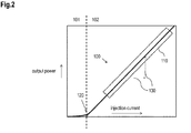
- Fig 2 shows a typical laser diode transfer curve 100, also called "laser transfer function”.
- a first region 101 is a sub-threshold region, also called “LED region”. In this region spontaneous emission of light occurs.
- a second region 102, above laser threshold is a laser active region, above which stimulated emission of light occurs.
- the intensity of the light (“output power") is proportional to the injection current through the device.
- This region 110 of the laser transfer function 110 may also be used for digital transmission of information.
- a key characteristic of the laser transfer function (also referred to as "L.I. Curve” (Output Light vs. Input Current)) are a threshold current 120 and a slope 130 in the linear region 110 beyond the threshold current 120, referred to as a slope efficiency.
- the laser basically is a current-to-light converter and the slope efficiency is a conversion factor.
- An efficiency of the laser is given by a ratio of optical intensity over injection current or power of emitted light over injection current , and the greater the slope efficiency the more efficient, thus providing higher optical power for a given current through the laser diode.
- the laser transfer function changes over time and temperature. With increasing temperature, the threshold current increases and the slope efficiency falls off exponentially. In addition, aging effects cause the threshold current to increase and the slope efficiency to fall off exponentially over the life time of the laser.
- a laser diode driver translates logic signals from the electrical domain to the optical domain, delivering current to the laser diode optionally monitoring its output, e.g., with a back facet monitor photo diode.
- Optical transponders commercially used are sensitive towards changes of the polarization of the emitted light ("wavelengths") and induced power fluctuation caused by polarization dependent gain (PDG) or polarization dependent loss (PDL). Due to dependencies of the power transfer from the pumps to the transport signal on the respective wavelength-polarization, Raman amplifiers can contribute significantly to PDG or PDL in case of insufficient design or control.
- wavelengths polarization dependent gain
- PDL polarization dependent loss
- Fig. 3 shows two schematic diagrams visualizing two different approaches to achieve depolarization of an optical signal provided by a pump, wherein exemplary depolarization of a single wavelength is illustrated.
- both setups shown in Fig. 4A and 4B can be combined into one amplifier.
- output ports providing signals with different wavelength can be connected to a wavelength combiner (which can be, e.g., an optical multiplexer) as shown in Fig. 1 .
- the setup according to Fig. 3B is based on a depolarizer 301 implemented, e.g., by a birefrigent optical fiber, which is connected to a laser diode 302. Quite small degrees of polarization ("DoP") can be achieved by an optimized adaptation of the length of the fiber to the linewidth of the pump lightwave.
- DoP degrees of polarization
- this setup is based on a single laser pump/diode 302, respective implementation is only useful if the pump power provided by the single laser diode 302 is sufficient.
- a polarization beam combiner 312 coupling the combined signal with orthogonal polarizations to an output fiber 313.
- the amount of total pump power concerning a single wavelength at the output of the polarization beam combiner 312 is almost two times the power of a single laser diode.
- the main challenge of this setup is the adjustment of the optical power of the light, emitted by both laser diodes 310, 311 in such a way that the power of emitted light is substantially equal for both orthogonal polarizations.
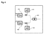
- Fig. 4 shows in a block diagram an example for a common approach to eliminate the negative effects of PDG and PDL based on a setup shown in Fig.3A by implementing monitoring devices 401, 402 in both input branches of the PBC 403 and calibrating the monitors devices 401, 402 at the end of the manufacturing process accordingly.
- the respective level of optical power of each of the optical signals (polarizations) emitted by the respective laser diode 404, 405 can be determined, wherein a driving current 406, 407 for the respective laser diode 404, 405 can be controlled and adjusted accordingly.
- the objective is thus to overcome such disadvantages and in particular to provide an improved solution for driving optical laser diodes implemented in optical amplifiers.
- a method for driving an optical laser diode during operation in an optical communication network comprising the following steps:
- the proposed solution implements an optical performance monitoring and recalibration technique during operation which can be based on a laser transfer function of the involved laser diodes, e.g. based on the characteristics of the laser transfer function.
- the characteristics may be or may be based on an actual "L.I.-Curve" of the laser diodes.
- component aging and temperature deviations can be determined and compensated at least partially or fully.
- Operation of a system or a network comprises any kind of information transfer based on analogue or digital transmission/modulation technology including e.g. respective service or maintenance windows of the system or the network.
- One further advantage of the proposed solution is the reduction of costs due to a reduced number of monitors (including e.g. photodiodes, optical couplers, optical splices and additional electronics) and due to a reduced number of polarization maintaining couplers, which may not be required for the proposed solution.
- monitors including e.g. photodiodes, optical couplers, optical splices and additional electronics
- polarization maintaining couplers which may not be required for the proposed solution.
- better stability over lifetime can be achieved by explicitly considering component aging during system operation.
- the laser transfer function is characterized by at least one of
- a forward voltage of the laser diode is determined and the threshold current is derived based on the forward voltage.
- the laser diode is driven by an injection current dependent on the control signal.
- a modulation is applied to the injection current.
- At least one parameter of light emitted by the laser diode is determined and the slope of the transfer function is derived based on the modulation and on the at least one parameter.
- the first laser diode is driven by a first injection current dependent on the first control signal and the second laser diode is driven by a second injection current dependent on the second control signal.
- the first laser transfer function is characterized by at least one of a threshold current of the first laser diode and a slope of a linear region beyond the threshold current of the first laser diode.
- the second laser transfer function is characterized by at least one of a threshold current of the second laser diode and a slope of a linear region beyond the threshold current of the second laser diode.
- a forward voltage of the first laser diode is determined and the threshold current of the first laser diode is derived based on the forward voltage of the first laser diode.
- a forward voltage of the second laser diode is determined and the threshold current of the second laser diode is derived based on the forward voltage of the second laser diode.
- a first modulation is applied to the first injection current and a second modulation is applied to the second injection current.
- At least one parameter related to light emitted by the first laser diode and at least one parameter related to light emitted by the second laser diode is determined.
- the slope of the first laser transfer function is derived based on the first modulation and based on the at least one parameter of light emitted by the first laser diode.
- the slope of the second laser transfer function is derived based on the second modulation and based on the at least one parameter of light emitted by the second laser diode.
- a modulation with a small amplitude and with a low frequency does not cause any negative effect at the respective receiver located at the other end of an optical link or span.
- a small modulation preferably with sinusoidal waveform, can be applied on the driving current of the laser diodes.
- the frequency of the modulation is preferably small enough to enable the equalization mechanism of the receiver to compensate the induced signal distortions.
- the first and the second modulation have a different diode-specific frequency.
- the first laser transfer function is determined based on the at least one parameter related to light emitted by the first laser diode and based on the frequency of the first modulation.
- the second laser transfer function is determined based on the least one parameter related to light emitted by the second laser diode and based on the frequency of the second modulation.
- Simultaneous determination of the respective slopes can also be accomplished for all laser diodes operating according to the proposed solution, including laser diodes with different wavelengths, by using different diode-specific frequencies for all laser diodes involved.
- only the first modulation is applied to the first injection current or the second modulation is applied to the second injection current at one instance of time.
- the light emitted by the first laser diode and the light emitted by the second laser diode are combined by a polarization beam combiner.
- the first and the second laser diode are driven such that the at least one parameter related to light emitted by the first laser diode and the at least one parameter related to light emitted by the second laser diode are substantially equal.
- the first and the second control signal are applied such that variations of the first and the second laser transfer function caused by component aging and/or temperature variations are at least partially compensated.
- the at least one parameter is based on the optical power of light.
- the optical power of the light, emitted by each laser diode can be easily adjusted such that the respective level of optical power is substantially equal. This is beneficial for operating optical amplifiers.
- a device for driving an optical laser diode during operation in an optical communication network comprising a control unit for determining a laser transfer function during operation of the laser diode in the optical communication network.
- the control unit is arranged such that a control signal is provided for driving the laser diode according to the laser transfer function.
- a communication system comprising at least one device as described herein and/or at least one optical amplifier as described herein.
- the optical amplifier 500 can be arranged as a Raman amplifier.
- this setup comprises a single optical monitor 510, e.g., an optical photo diode.
- the optical monitor is coupled to a polarization beam combiner 520.
- the amplifier 500 further comprises two optical laser diodes 530, 531 which are separately connected to the polarization beam combiner 520.
- the first laser diode 530 is connected to a first electrical adding element 540, which is additionally connected to a first modulator 550 and a first control circuit 560.
- the second laser diode 531 is coupled to a second electrical adding element 541, which is additionally connected to a second modulator 551 and a second control circuit 561.
- a first electrical driving current 570 is provided to an input of the first laser diode 530 and a second electrical driving current 571 is provided to an input of the second laser diode 531.
- the setup according to Fig. 5 uses the single optical monitor 510 for determining the total power of light at the given wavelength emitted at the output of the polarization beam combiner 520.
- a self-calibration step (also called “initial scan") is performed by determining the output power versus driving current for both laser diodes 530, 531. During this scan only one of the laser diodes 530, 531 is active while varying the driving current form zero to a predetermined maximum value. Contemporarily, the voltage (not shown in Fig.6 ) applied to the laser diode 530, 531 can also be monitored. Based on that initial calibration, the L.I.-Curve is determined for both laser diodes 530, 531.
- Fig.6 shows an example of an L.I.-Curve (laser transfer function) 610 as an exemplary result of the aforementioned initial scan.
- L.I.-Curve laser transfer function
- Fig 6 additionally shows a graph 620 visualizing the increasing course of the forward voltage 655 applied to the laser diodes 530, 531 with increasing driving current 660.
- Fig.7 shows as an exemplary outcome of the initial calibration of an optical amplifier the respective L.I.-Curve determined for a first and second laser diode (pumps), e.g. being part of an optical amplifier as shown in Fig.5 .
- umps first and second laser diode
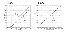
- Fig. 7A shows a graph 810 visualizing a relation (L.I.-Curve) between optical output power and a driving current of the first laser diode and a graph 820 visualizing a L.I.-Curve of the second laser diode.
- the threshold current and the slope of the respective L.I. Curve 810, 820 is different for the two laser diodes. Based on the determined L.I.-Curves 810, 820 both laser diodes can be adjusted such, that the respective output power (power of light), emitted by both laser diodes, is substantially equal.
- Fig. 7B shows a graph 850 visualizing exemplarily the relation between the respective driving currents ("current pump") for the two pumps calibrated according to Fig.7A and adjusted such, that the optical output power of the respective emitted light is substantially equal.
- Fig.8 shows an exemplary control scheme for an optical amplifier 700.
- the optical amplifier 700 is arranged as a Raman amplifier which can be part of an optical communication network.
- An optical output of a first laser diode 710 is connected to a first input of a polarization beam combiner 720.
- An optical output of a second laser diode 711 is connected to a second input of the polarization beam combiner 720.
- An optical signal 725 in particular an optical power of emitted light at the output of the polarization beam combiner 720, is monitored by an optical power monitor 730 which is connected to a detector 735, also referred to as "small signal low frequency detector", which will be explained further below.
- the detector 735 is connected to an input 747 of a control circuit 740.
- a first output 743 of the control circuit 740 is coupled to a first current driver 761, which supplies a signal to a first adding element 765, where it is combined with a signal from a first modulator 770, also referred to as "small signal low frequency modulator” (which will be explained below), into a signal 779.
- a second output 744 of the control circuit 740 is coupled to a second current driver 760, which feeds a signal to a second adding element 766, where it is combined with a signal form a second modulator 771 into a signal 778.
- the output of the first adding element 765 drives the first laser diode 710 and the output of the second adding element 766 drives the second laser diode 711.
- the signal 779 is also referred to as an injection current or driving current to the first laser diode 710.
- the signal 778 is also referred to as an injection current or driving current to the second laser diode 711.
- a first voltage measurement unit 790 is connected across two measurement pins 717, 718 of the first laser diode 710.
- a second voltage measurement unit 791 is connected across two measurement pins 715, 716 of the second laser diode 711.
- An output of the first voltage measurement unit 790 is coupled to an input 745 of the control circuit 740 and an output of the second voltage measurement unit 791 is coupled to an input 746 of the control circuit 740.
- the control unit 740 comprises a storage 748 for storing a first L.I.-Curve 741 of the first laser diode 710 and a second L.I.-Curve 742 of the second laser diode 711.
- both L.I.-Curves 741, 742 were determined and stored in the storage 748 during an initial activation of the Raman amplifier 700, i.e. during self-calibration as explained with regard to Fig.5 and Fig.6 .
- One further aspect of the proposed solution is related to an ongoing recalibration step for updating the stored L.I.-Curves 741, 742, performed continuously during operation of the Raman amplifier 700. Continuous recalibration is beneficial to achieve correct system operation during the lifetime of the laser diodes 710, 711.
- Calibration as usually performed during activation of the system may otherwise disturb ongoing data traffic during active system operation.
- Fig.9 shows a diagram depicting a relation between an output power in view of an injection current, wherein both parameters can be determined, in particular measured, during system operation.
- a correlation (also referred to as an L.I.-Curve 100) between an optical output power 160 and an injection current 170 can be derived for an operating range 110, e.g., if a "threshold current" 120 and a "slope of the L.I.-curve" 130 can be determined.
- Both parameters 120, 130 can be derived from two other physical parameters:
- the respective forward voltage applied to the two laser diodes 710, 711 can be determined by the voltage measurement units 790, 791.
- a signal 794 representing the measured amount of the actual forward voltage applied to the first laser diode 710 is provided to the input 745 of the control circuit 740.
- a signal 793 representing the measured amount of the actual forward voltage applied to the second laser diode 711 is provided to the input 746 of the control circuit 740.
- the actual amounts of the respective threshold currents of the laser diodes 710, 711 can be determined by the control unit 740.
- the modulation applied by the respective modulators 770, 771 to each injection current 778, 779 of the laser diodes 710, 711 can be detected by the detector 735, connected to the optical power monitor 730.
- the optical output power of the signal 725 can thus be determined by the detector 735.
- Determining the output power can be performed serially for each involved laser diode 710, 711, i.e. subsequently for one laser diode after the other (in an alternating fashion). Alternatively, this can also be performed for both laser diodes 710, 711 simultaneously by modulating the injection currents 778, 779 with slightly different modulation frequencies, which can be distinguished by the optical power monitor 730 and/or the detector 735.
- a signal 795 representing the determined output power of the signal 725 is provided via the detector 735 to the control circuit 740.
- the modulation index 150 can be determined by the control unit 740.
- the modulation index 150 is used to derive the respective slope of the L.I.-Curves of the laser diodes 710, 711.
- a further signal may be provided to the control circuit 740 (according to an alternative embodiment, not shown), representing the overall output power of the signal 725, which might be also useful for updating the L.I.-Curves and adjusting the control signals 749, 750.
- the L.I.-Curves 741, 742 stored in the control unit 740 can be updated.
- a "small signal low frequency modulation" 770, 771 does not cause a negative effect on a receiver side.
- Optical receivers that are based on coherent detection apply equalization techniques allowing compensation of small signal distortions, in particular in case of slow signal variations.
- a small modulation preferably with sinusoidal waveform, can be applied on the driving current of the laser diodes.
- the frequency of the modulation is preferably low enough to enable the equalization mechanism on the receiver side to compensate the induced signal distortions.
- Degradation monitoring Since aging causes performance degradation over time, the slope and the threshold degradation can be monitored rather infrequently, e.g., once per day or even once per week. Therefore, it is also an option to apply the monitoring ("degradation monitoring") only during, e.g., service or maintenance of the optical system/network or during operation which is unsusceptible for small distortions.
- An information about times suitable for monitoring can be, e.g., communicated by the management system based on a preFEC bit error rate (BER) of the transponders, which is a bit error rate determined before correction of potential transmission errors by a forward error correction (FEC).
- BER bit error rate
- InGaAsP InGaAs
- InP laser diodes typically causes a decrease of the diode-specific forward voltage at a given driving current.
- an increase of the diode-specific threshold current can be derived from the measured decrease of the forward voltage, given that the aforementioned correlation between these two parameters is known dependent on the type of the laser diode.
- An advantage of the proposed solution is a continuous or iterative determination of key parameters used for updating the L.I.-Curves during operation of an optical system or optical communication network.
- updated L.I. Curves 741, 742 of the laser diodes 710, 711 are made available at all times, which allows "on-time" feed forward control of the laser diodes 710, 711.
- An appropriate control signal 750 is provided by the control unit 740 to the first current driver 761. Accordingly, the control signal 749 is provided by the control unit 740 to the second current driver 760. Dependent on the control signals 750, 749 the first and second current drivers 761, 760 can be adjusted.
- control signals 750, 749 can be generated such that the output power of the light emitted by each laser diode 710, 711 is substantially equal. This is advantageous for a proper operation of optical amplifiers, in particular Raman amplifiers.
- High power optical pumps used for Raman applications may comprise a thermoelectric cooler (TEC) using the "Peltier effect" for stabilizing a chip temperature at a predefined value.
- TEC thermoelectric cooler
- pumps without TEC may be implemented in Raman applications, which makes monitoring the impact of varying temperatures on optical pumps a beneficial feature of the current solution.
- the forward voltage decreases with an increasing temperature at a constant driving current.
- the proposed solution can also be applied for driving laser diodes operated at different temperatures.
- Effects based on a significant amount of aging and/or high temperature may result in a modified shape of the L.I.-Curve, e.g., a curvature instead of a straight line.
- a modified shape of the L.I.-Curve e.g., a curvature instead of a straight line.
- Such kind of operating conditions are not suitable for Raman amplification.
- Such model of the L.I.-Curve may be used as a basis for driving the laser diode under varying conditions to achieve a proper and suitable operation of the Raman amplification.
Landscapes
- Physics & Mathematics (AREA)
- Electromagnetism (AREA)
- Optics & Photonics (AREA)
- Engineering & Computer Science (AREA)
- Plasma & Fusion (AREA)
- General Physics & Mathematics (AREA)
- Condensed Matter Physics & Semiconductors (AREA)
- Computer Networks & Wireless Communication (AREA)
- Signal Processing (AREA)
- Automation & Control Theory (AREA)
- Optical Modulation, Optical Deflection, Nonlinear Optics, Optical Demodulation, Optical Logic Elements (AREA)
- Semiconductor Lasers (AREA)
- Optical Communication System (AREA)
Abstract
A method and a device is provided driving an optical laser diode (710, 711) during operation in an optical communication network, by
- determining a laser transfer function (741, 742) during operation of the laser diode (710, 711) and
- providing a control signal (750, 749) for driving the laser diode (710, 711) according to the laser transfer function (741, 742).
- determining a laser transfer function (741, 742) during operation of the laser diode (710, 711) and
- providing a control signal (750, 749) for driving the laser diode (710, 711) according to the laser transfer function (741, 742).
The LD emission may be polarisation combined with the output of a second LD to provide non-polarized pumping light for a Raman optical amplifier used in an optical communication device. After the self-calibration of the two LD, during operation the calibration can be controlled by providing a modulation (770,771) on the LD bias current (778,779) and detecting (790,791) the voltage (716,718) over the LD (710,711). This information is used to update the L-I-slope as stored in the controller (740). Only a single monitor photodiode (730) is used for pump power stabilisation of the Raman amplifier as the control of the individual LD output power is performed via voltage and current measurements at the laser diodes.
Description
- The invention relates to a method and to a device for driving optical laser diode(s) in an optical communication network.
- In addition, an according optical amplifier and a communication system are suggested.
- Optical amplifiers are used in optical communication networks to intensify, e.g., optical signals that are attenuated along the fiber-optic communication path within optical communication networks.
- In fiber-optic communication networks, wavelength-division multiplexing (WDM) is a technology which multiplexes a number of optical carrier signals onto a single optical fiber by using different wavelengths (i.e. colors) of laser light. This technique enables bidirectional communications over one strand of fiber, as well as multiplication of capacity.
- Raman amplification as one example of optical amplification is based on the Stimulated Raman Scattering (SRS) phenomenon, when a lower frequency signal induces an inelastic scattering of a higher-frequency pump photon in an optical medium in the nonlinear regime. As a result of this, another lower-frequency signal photon is produced and the higher-frequency pump photon is annihilated, with the surplus energy resonantly passed to the vibrational states of the medium. This process, as with other stimulated emission processes, allows all-optical amplification.
- Raman amplification is an important technology to increase a maximum distance covered by long-haul optical transmission systems and is a suitable technology to supplement erbium-doped fiber amplifiers (EDFAs) commonly used in commercial installations. According to its large bandwidth, Raman amplification is compatible with the requirements of wavelength-division multiplexing (WDM) networks. One of the main advantages of Raman amplification is the usage of transmission fiber as gain medium, providing distributed amplification.
- The trend to higher data rates per wavelength channel requires an improvement of the optical signal-to-noise ratio (OSNR) performance of optical transmission links or spans. In many scenarios, an insertion of additional inline amplifiers is not possible. Hence, Raman amplification is expected to be applied more frequently in future optical networks.
- A Raman amplifier is an optical amplifier based on Raman gain, which results from the effect of stimulated Raman scattering. An input signal can be amplified while co-propagating or counter-propagating with a pump beam. A Raman amplifier is preferably, but not necessarily, pumped with continuous-wave light from a diode laser. Signal amplification can be achieved by transferring power from one or more optical pumps to, e.g., a WDM signal. Direct power transfer is possible, but power transfer can also be provided via some additional lightwaves (also called higher-order pumping).
- Pumping lightwaves are usually coupled into the transmission fiber at the end of the link, propagating in opposite direction to the signals. This "counter directional pumping" results in an improved optical signal-to-noise ratio (OSNR).
- "Co directional pumping" results in a reduction of the nonlinear fiber effects, achieving the same output power level at the output of the transmission fiber with reduced nonlinear interactions as without Raman amplification.
- Transients are power variations of signals, induced by adding or dropping of optical channels, which can be caused, e.g., by fiber breaks or component failure and result in significant performance degradation. Such kind of impairments can be mitigated by launching additional lightwaves into the fiber ("filling laser") and by keeping the total power coupled into a span almost constant, even if some of the channels are dropped.
-
Fig. 1 shows an exemplary setup of a Raman amplifier, wherein several wavelengths λ1...λ4 of emitted light ("pump wavelength") are used to achieve similar gain for all wavelength signals ("gain flatness"). Each pump wavelength λ1...λ4 is provided by a laser pump LP1...4 comprising two laser diodes LD1,2, wherein the emitted light at the output of the respective laser diodes LD1,2 is combined by a polarization beam combiner PBC within each of the laser pumps LP1...4. The provided pump wavelengths λ1...λ4 are combined by a multiplexer MUX, injecting a combined signal cs (λ1...λ4) into a transmission fiber TF in opposite direction to a transport signal ts. - Laser diodes, which are used in optical communication networks or optical communication systems typically come in a package that includes a pigtail pre-aligned with the laser and a back facet monitor photo diode. For a simple digital transmission, the laser diode is driven such that laser light intensity is modulated so that each digital level has a distinct optical power. The optical digital level must be kept constant over time and temperature to ensure network integrity.
-
Fig 2 shows a typical laserdiode transfer curve 100, also called "laser transfer function". There are tworegions laser transfer function 100. Afirst region 101 is a sub-threshold region, also called "LED region". In this region spontaneous emission of light occurs. Asecond region 102, above laser threshold is a laser active region, above which stimulated emission of light occurs. In alinear region 110 the intensity of the light ("output power") is proportional to the injection current through the device. Thisregion 110 of thelaser transfer function 110 may also be used for digital transmission of information. A key characteristic of the laser transfer function (also referred to as "L.I. Curve" (Output Light vs. Input Current)) are athreshold current 120 and aslope 130 in thelinear region 110 beyond thethreshold current 120, referred to as a slope efficiency. - The laser basically is a current-to-light converter and the slope efficiency is a conversion factor. An efficiency of the laser is given by a ratio of optical intensity over injection current or power of emitted light over injection current , and the greater the slope efficiency the more efficient, thus providing higher optical power for a given current through the laser diode.
- Unfortunately, the laser transfer function changes over time and temperature. With increasing temperature, the threshold current increases and the slope efficiency falls off exponentially. In addition, aging effects cause the threshold current to increase and the slope efficiency to fall off exponentially over the life time of the laser.
- A laser diode driver translates logic signals from the electrical domain to the optical domain, delivering current to the laser diode optionally monitoring its output, e.g., with a back facet monitor photo diode.
- Optical transponders commercially used are sensitive towards changes of the polarization of the emitted light ("wavelengths") and induced power fluctuation caused by polarization dependent gain (PDG) or polarization dependent loss (PDL). Due to dependencies of the power transfer from the pumps to the transport signal on the respective wavelength-polarization, Raman amplifiers can contribute significantly to PDG or PDL in case of insufficient design or control.
- Significant power transfer is mainly possible for copolarized light (lightwaves) whereas the signal gain is almost zero for orthogonally polarized lightwaves.
- Due to the polarization dependency, implementation of a single pump lightwave, emitted by a single laser diode is not suitable for signal amplification in WDM systems or networks. Rather a depolarization of the pump is required to achieve polarization independent amplification and performance.
-
Fig. 3 shows two schematic diagrams visualizing two different approaches to achieve depolarization of an optical signal provided by a pump, wherein exemplary depolarization of a single wavelength is illustrated. As a further exemplary embodiment (not shown) both setups shown inFig. 4A and 4B can be combined into one amplifier. Furthermore, output ports providing signals with different wavelength can be connected to a wavelength combiner (which can be, e.g., an optical multiplexer) as shown inFig. 1 . - The setup according to
Fig. 3B is based on adepolarizer 301 implemented, e.g., by a birefrigent optical fiber, which is connected to alaser diode 302. Quite small degrees of polarization ("DoP") can be achieved by an optimized adaptation of the length of the fiber to the linewidth of the pump lightwave. As this setup is based on a single laser pump/diode 302, respective implementation is only useful if the pump power provided by thesingle laser diode 302 is sufficient. - However, due to improvements, the power emitted by pump laser diodes in the wavelength range from 1420 nm to 1480 nm has been increased which allows several implementations of this setup in commercial systems.
- Still, the power provided by a single laser diode is insufficient for many applications. Hence, a setup according to
Fig. 3A is used. - According to this setup, shown in
Fig.3A , lightwaves provided by twolaser diodes output fiber 313. Thereby the amount of total pump power concerning a single wavelength at the output of thepolarization beam combiner 312 is almost two times the power of a single laser diode. - Since differences in power levels will cause PDG or PDL, the main challenge of this setup is the adjustment of the optical power of the light, emitted by both
laser diodes - The same applies to setups to mitigate transient effects.
-
Fig. 4 shows in a block diagram an example for a common approach to eliminate the negative effects of PDG and PDL based on a setup shown inFig.3A by implementingmonitoring devices PBC 403 and calibrating themonitors devices respective laser diode respective laser diode - Known solutions as mentioned above do have some significant drawbacks:
- Two optical monitors are required, one per laser diode, each monitor comprises respectively a photo diode, an optical coupler and an optical splice which involves additional costs;
- As the monitors are usually calibrated during the manufacturing process, variations in the transfer function caused, e.g., by component aging or temperature deviations have not been considered. As a consequence, according to an exemplary worst case scenario, the optical power of the light emitted via one of the input branches of the PBC would decrease ("insertion loss") which causes non-identical power levels of the polarizations at the output of the PBC;
- Polarization maintaining couplers and splices are required, which causes significant technical complexity in the manufacturing process.
- The objective is thus to overcome such disadvantages and in particular to provide an improved solution for driving optical laser diodes implemented in optical amplifiers.
- This problem is solved according to the features of the independent claims. Further embodiments result from the depending claims.
- In order to overcome this problem, a method is provided for driving an optical laser diode during operation in an optical communication network comprising the following steps:
- determining a laser transfer function during operation of the laser diode;
- providing a control signal for driving the laser diode according to the laser transfer function.
- The proposed solution implements an optical performance monitoring and recalibration technique during operation which can be based on a laser transfer function of the involved laser diodes, e.g. based on the characteristics of the laser transfer function. The characteristics may be or may be based on an actual "L.I.-Curve" of the laser diodes. Due to ongoing monitoring and recalibration, in particular during operation of an optical system or communication network, an improved performance of optical amplifiers as well as optical communication systems based on such kind of optical amplifiers can be achieved. Beneficially, component aging and temperature deviations can be determined and compensated at least partially or fully.
- Operation of a system or a network comprises any kind of information transfer based on analogue or digital transmission/modulation technology including e.g. respective service or maintenance windows of the system or the network.
- One further advantage of the proposed solution is the reduction of costs due to a reduced number of monitors (including e.g. photodiodes, optical couplers, optical splices and additional electronics) and due to a reduced number of polarization maintaining couplers, which may not be required for the proposed solution. As a further benefit, better stability over lifetime can be achieved by explicitly considering component aging during system operation.
- As a further advantage, complexity of manufacturing can be reduced because only two polarization maintaining splices are necessary for the proposed solution instead of four. Consequently, manufacturing time for optical amplifiers based on the proposed solution can be reduced.
- In an embodiment, the laser transfer function is characterized by at least one of
- a threshold current of the laser diode,
- a slope of a linear region beyond the threshold current.
- In a further embodiment, a forward voltage of the laser diode is determined and the threshold current is derived based on the forward voltage.
- In a next embodiment, the laser diode is driven by an injection current dependent on the control signal. A modulation is applied to the injection current. At least one parameter of light emitted by the laser diode is determined and the slope of the transfer function is derived based on the modulation and on the at least one parameter.
- The problem stated above is also solved by a method for driving a first and a second laser diode during operation in an optical communication network, comprising the following steps:
- determining a first laser transfer function during operation of the first laser diode;
- determining a second laser transfer function during operation of the second laser diode;
- providing a first control signal for driving the first laser diode according to the first laser transfer function, and
- providing a second control signal for driving the second laser diode according to the second laser transfer function.
- In yet another embodiment the first laser diode is driven by a first injection current dependent on the first control signal and the second laser diode is driven by a second injection current dependent on the second control signal.
- According to a next embodiment, the first laser transfer function is characterized by at least one of a threshold current of the first laser diode and a slope of a linear region beyond the threshold current of the first laser diode. The second laser transfer function is characterized by at least one of a threshold current of the second laser diode and a slope of a linear region beyond the threshold current of the second laser diode.
- In yet another embodiment, a forward voltage of the first laser diode is determined and the threshold current of the first laser diode is derived based on the forward voltage of the first laser diode. A forward voltage of the second laser diode is determined and the threshold current of the second laser diode is derived based on the forward voltage of the second laser diode.
- Pursuant to another embodiment, a first modulation is applied to the first injection current and a second modulation is applied to the second injection current. At least one parameter related to light emitted by the first laser diode and at least one parameter related to light emitted by the second laser diode is determined. The slope of the first laser transfer function is derived based on the first modulation and based on the at least one parameter of light emitted by the first laser diode. The slope of the second laser transfer function is derived based on the second modulation and based on the at least one parameter of light emitted by the second laser diode.
- Advantageously, a modulation with a small amplitude and with a low frequency (also called "small signal low frequency modulation" ) does not cause any negative effect at the respective receiver located at the other end of an optical link or span. Actual optical receivers, based on coherent detection, apply sophisticated equalization techniques allowing compensation of small signal distortions, in particular in case of slow signal variations. Hence, a small modulation, preferably with sinusoidal waveform, can be applied on the driving current of the laser diodes. The frequency of the modulation is preferably small enough to enable the equalization mechanism of the receiver to compensate the induced signal distortions. By detecting the related modulation in the emitted light received, e.g., by an optical monitor, the slope of the L.I.-Curve of the respective laser diode can be determined.
- According to an embodiment, the first and the second modulation have a different diode-specific frequency. The first laser transfer function is determined based on the at least one parameter related to light emitted by the first laser diode and based on the frequency of the first modulation. The second laser transfer function is determined based on the least one parameter related to light emitted by the second laser diode and based on the frequency of the second modulation.
- By using a different frequency for each laser diode with identical wavelength, simultaneous determination of the slope for both laser diodes is feasible.
- Simultaneous determination of the respective slopes can also be accomplished for all laser diodes operating according to the proposed solution, including laser diodes with different wavelengths, by using different diode-specific frequencies for all laser diodes involved.
- According to another embodiment, only the first modulation is applied to the first injection current or the second modulation is applied to the second injection current at one instance of time.
- Pursuant to another embodiment, the light emitted by the first laser diode and the light emitted by the second laser diode are combined by a polarization beam combiner.
- In yet another embodiment, the first and the second laser diode are driven such that the at least one parameter related to light emitted by the first laser diode and the at least one parameter related to light emitted by the second laser diode are substantially equal.
- Pursuant to another embodiment, the first and the second control signal are applied such that variations of the first and the second laser transfer function caused by component aging and/or temperature variations are at least partially compensated.
- According to a next embodiment, the at least one parameter is based on the optical power of light.
- Based on the continuously updated characteristics of the respective laser diodes the optical power of the light, emitted by each laser diode can be easily adjusted such that the respective level of optical power is substantially equal. This is beneficial for operating optical amplifiers.
- The problem stated above is also solved by a device for driving an optical laser diode during operation in an optical communication network, comprising a control unit for determining a laser transfer function during operation of the laser diode in the optical communication network. The control unit is arranged such that a control signal is provided for driving the laser diode according to the laser transfer function.
- The problem stated above is also solved by an optical amplifier comprising
- at least two devices as described above which are used as optical pumps;
- a polarization beam combiner combining light emitted by each of the optical pumps;
- a detector determining at least one parameter of a combined light emitted by the polarization beam combiner,
- the control unit of each device is arranged such that the respective laser transfer function is determined based on the at least one parameter of the combined light.
- The problem stated above is further solved by a communication system comprising at least one device as described herein and/or at least one optical amplifier as described herein.
- Embodiments of the invention are shown and illustrated in the following figures:
- Fig.5
- shows a schematic block diagram of an optical amplifier;
- Fig.6
- shows an example of an L.I.-Curve as an exemplary result of an initial calibration of a laser diode;
- Fig.7
- shows an exemplary result of an initial calibration of an optical amplifier comprising two laser diodes;
- FIG.8
- shows an exemplary control scheme of an optical amplifier;
- FIG.9
- shows in a diagram the relation between physical parameters, being measureable during system operation, and key parameters characterizing the L.I.-Curve.
- With reference to
Fig.5 , in a block diagram, a schematic overview of anoptical amplifier 500 according to the proposed solution is shown. Theoptical amplifier 500 can be arranged as a Raman amplifier. In contrast to prior solutions this setup comprises a singleoptical monitor 510, e.g., an optical photo diode. The optical monitor is coupled to apolarization beam combiner 520. Theamplifier 500 further comprises twooptical laser diodes polarization beam combiner 520. Thefirst laser diode 530 is connected to a first electrical addingelement 540, which is additionally connected to afirst modulator 550 and afirst control circuit 560. Thesecond laser diode 531 is coupled to a second electrical addingelement 541, which is additionally connected to asecond modulator 551 and asecond control circuit 561. A first electrical driving current 570 is provided to an input of thefirst laser diode 530 and a second electrical driving current 571 is provided to an input of thesecond laser diode 531. - The setup according to
Fig. 5 uses the singleoptical monitor 510 for determining the total power of light at the given wavelength emitted at the output of thepolarization beam combiner 520. - Before starting operation of the
amplifier 500, e.g., in an optical communication system or network, a self-calibration step (also called "initial scan") is performed by determining the output power versus driving current for bothlaser diodes laser diodes Fig.6 ) applied to thelaser diode laser diodes -
Fig.6 shows an example of an L.I.-Curve (laser transfer function) 610 as an exemplary result of the aforementioned initial scan. Up to a certain value of current ("threshold current") 615 no radiation is observed and theoptical output power 650 of the laser diode is almost zero. By exceeding thethreshold 615, theoptical output power 650 increases almost linearly with the drive current 660. -
Fig 6 additionally shows agraph 620 visualizing the increasing course of theforward voltage 655 applied to thelaser diodes -
Fig.7 shows as an exemplary outcome of the initial calibration of an optical amplifier the respective L.I.-Curve determined for a first and second laser diode (pumps), e.g. being part of an optical amplifier as shown inFig.5 . -
Fig. 7A , shows agraph 810 visualizing a relation (L.I.-Curve) between optical output power and a driving current of the first laser diode and agraph 820 visualizing a L.I.-Curve of the second laser diode. - According to
Fig.7A , the threshold current and the slope of the respective L.I.Curve Curves -
Fig. 7B shows agraph 850 visualizing exemplarily the relation between the respective driving currents ("current pump") for the two pumps calibrated according toFig.7A and adjusted such, that the optical output power of the respective emitted light is substantially equal. - As long as the aging effects of the monitor (photodiode, coupler) and other components (except the polarization beam combiner) affects both emitted lights, i.e. both polarizations in the same way, no polarization dependent loss (PDL) and no polarization dependent gain (PDG) is induced.
- However, in some scenarios optical systems are running for several years without being turned off. In such kind of situations, aging of the laser diodes, particularly individual aging of the laser diodes may disturb the balance between the two laser diodes (pumps).
- In order to maintain the performance of the system over lifetime it is important to detect performance degradation of the laser characteristics during system operation. This can be achieved by the proposed solution.
-
Fig.8 shows an exemplary control scheme for anoptical amplifier 700. Theoptical amplifier 700 is arranged as a Raman amplifier which can be part of an optical communication network. - An optical output of a
first laser diode 710 is connected to a first input of apolarization beam combiner 720. An optical output of asecond laser diode 711 is connected to a second input of thepolarization beam combiner 720. Anoptical signal 725, in particular an optical power of emitted light at the output of thepolarization beam combiner 720, is monitored by anoptical power monitor 730 which is connected to adetector 735, also referred to as "small signal low frequency detector", which will be explained further below. Thedetector 735 is connected to aninput 747 of acontrol circuit 740. Afirst output 743 of thecontrol circuit 740 is coupled to a firstcurrent driver 761, which supplies a signal to a first addingelement 765, where it is combined with a signal from afirst modulator 770, also referred to as "small signal low frequency modulator" (which will be explained below), into asignal 779. Asecond output 744 of thecontrol circuit 740 is coupled to a secondcurrent driver 760, which feeds a signal to a second addingelement 766, where it is combined with a signal form asecond modulator 771 into asignal 778. - The output of the first adding
element 765 drives thefirst laser diode 710 and the output of the second addingelement 766 drives thesecond laser diode 711. - The
signal 779 is also referred to as an injection current or driving current to thefirst laser diode 710. Thesignal 778 is also referred to as an injection current or driving current to thesecond laser diode 711. - A first
voltage measurement unit 790 is connected across twomeasurement pins first laser diode 710. A secondvoltage measurement unit 791 is connected across twomeasurement pins second laser diode 711. An output of the firstvoltage measurement unit 790 is coupled to aninput 745 of thecontrol circuit 740 and an output of the secondvoltage measurement unit 791 is coupled to aninput 746 of thecontrol circuit 740. - The
control unit 740 comprises astorage 748 for storing a first L.I.-Curve 741 of thefirst laser diode 710 and a second L.I.-Curve 742 of thesecond laser diode 711. According to an exemplarily scenario, both L.I.-Curves storage 748 during an initial activation of theRaman amplifier 700, i.e. during self-calibration as explained with regard toFig.5 andFig.6 . - One further aspect of the proposed solution is related to an ongoing recalibration step for updating the stored L.I.-
Curves Raman amplifier 700. Continuous recalibration is beneficial to achieve correct system operation during the lifetime of thelaser diodes - Calibration as usually performed during activation of the system (see, e.g., description concerning
Fig.5 andFig.6 ) may otherwise disturb ongoing data traffic during active system operation. - It is thus an advantage of the proposed solution that a relation between an optical power of emitted light and an injection current of a laser diode can be determined also during system operation in particular without any interruption of data traffic. Key parameters, representing the L.I.-Curve, can be derived from physical parameters that can be measured during system operation.
-
Fig.9 shows a diagram depicting a relation between an output power in view of an injection current, wherein both parameters can be determined, in particular measured, during system operation. - According to
Fig.9 , a correlation (also referred to as an L.I.-Curve 100) between anoptical output power 160 and an injection current 170 can be derived for anoperating range 110, e.g., if a "threshold current" 120 and a "slope of the L.I.-curve" 130 can be determined. Bothparameters - There is an unambiguous relation (indicated by a double arrow 105) between the "threshold current" 120 and a forward voltage 140 (representing the first physical parameter) applied to the respective laser diode, which can be measured during system operation. Determination of this relation, which is, e.g., dependent on the type of each laser diode, can be part of calibration measurements during the manufacturing process of the laser diode. Knowing that relation and based on the actual measurement result of the
forward voltage 140, the actual amount of the threshold current 120 of the laser diode can be determined. - The slope of the L.I.-
Curve 130 can be determined by applying a modulation with a low amplitude and a low frequency ("small signal low frequency modulation") to the injection current 170 of the laser diode, resulting in a respective modulation of theoutput power 160, which can be detected in the light emitted by the laser diode. Based on the modulated injection current 170, driving the laser diode and based on the resulting modulatedoptical output power 160, a modulation index 150 (representing the second physical parameter shown inFig.9 ) of the "small signal low frequency modulation" can be determined. Themodulation index 150 is the basis (indicated by an double arrow 106) for determining theslope 130 of the actual L.I.-Curve 100. - With regard to the
Raman amplifier 700 shown inFig.8 , the respective forward voltage applied to the twolaser diodes voltage measurement units first laser diode 710 is provided to theinput 745 of thecontrol circuit 740. Accordingly, a signal 793 representing the measured amount of the actual forward voltage applied to thesecond laser diode 711 is provided to theinput 746 of thecontrol circuit 740. - Based on the forward voltages and based on calibration results derived during the manufacturing process of the laser diodes (which can also be stored in the control unit 740), the actual amounts of the respective threshold currents of the
laser diodes control unit 740. - The modulation applied by the
respective modulators laser diodes detector 735, connected to theoptical power monitor 730. The optical output power of thesignal 725 can thus be determined by thedetector 735. - Determining the output power can be performed serially for each
involved laser diode laser diodes injection currents optical power monitor 730 and/or thedetector 735. - A
signal 795 representing the determined output power of thesignal 725 is provided via thedetector 735 to thecontrol circuit 740. Thus, on the output of thedetector 735 and the modulation applied by therespective modulators modulation index 150 can be determined by thecontrol unit 740. Themodulation index 150 is used to derive the respective slope of the L.I.-Curves of thelaser diodes - A further signal may be provided to the control circuit 740 (according to an alternative embodiment, not shown), representing the overall output power of the
signal 725, which might be also useful for updating the L.I.-Curves and adjusting the control signals 749, 750. - With the actual key parameters ("threshold current" and "slope") for the L.I.-Curves of the
respective laser diodes Curves control unit 740 can be updated. - Advantageously, applying a "small signal low frequency modulation" 770, 771 does not cause a negative effect on a receiver side. Optical receivers that are based on coherent detection apply equalization techniques allowing compensation of small signal distortions, in particular in case of slow signal variations. Hence, a small modulation, preferably with sinusoidal waveform, can be applied on the driving current of the laser diodes. The frequency of the modulation is preferably low enough to enable the equalization mechanism on the receiver side to compensate the induced signal distortions.
- Since aging causes performance degradation over time, the slope and the threshold degradation can be monitored rather infrequently, e.g., once per day or even once per week. Therefore, it is also an option to apply the monitoring ("degradation monitoring") only during, e.g., service or maintenance of the optical system/network or during operation which is unsusceptible for small distortions. An information about times suitable for monitoring can be, e.g., communicated by the management system based on a preFEC bit error rate (BER) of the transponders, which is a bit error rate determined before correction of potential transmission errors by a forward error correction (FEC).
- As an example, degradation of InGaAsP (InGaAs)/InP laser diodes typically causes a decrease of the diode-specific forward voltage at a given driving current. Hence, according to the proposed solution, an increase of the diode-specific threshold current can be derived from the measured decrease of the forward voltage, given that the aforementioned correlation between these two parameters is known dependent on the type of the laser diode.
- An advantage of the proposed solution is a continuous or iterative determination of key parameters used for updating the L.I.-Curves during operation of an optical system or optical communication network. Preferably, updated L.I.
Curves laser diodes laser diodes appropriate control signal 750 is provided by thecontrol unit 740 to the firstcurrent driver 761. Accordingly, thecontrol signal 749 is provided by thecontrol unit 740 to the secondcurrent driver 760. Dependent on the control signals 750, 749 the first and secondcurrent drivers - Based on the updated characteristics of the respective laser diodes ("optical pumps"), the control signals 750, 749 can be generated such that the output power of the light emitted by each
laser diode - High power optical pumps used for Raman applications may comprise a thermoelectric cooler (TEC) using the "Peltier effect" for stabilizing a chip temperature at a predefined value. In the future, pumps without TEC may be implemented in Raman applications, which makes monitoring the impact of varying temperatures on optical pumps a beneficial feature of the current solution.
- Higher temperatures cause an increased value of the threshold current and a reduced value of the slope of the respective L.I.-Curve.
- Furthermore, the forward voltage decreases with an increasing temperature at a constant driving current.
- The aforementioned impact of varying, in particular increasing temperature on the characteristics of the L.I-Curve is similar to the effect of a decreasing reliability and degradation of the laser diode caused by component aging.
- Consequently, the proposed solution can also be applied for driving laser diodes operated at different temperatures.
- Effects based on a significant amount of aging and/or high temperature may result in a modified shape of the L.I.-Curve, e.g., a curvature instead of a straight line. Normally, such kind of operating conditions are not suitable for Raman amplification. As a further advantage of the proposed solution, it is feasible to model the modified shape of the L.I.-Curve. Such model of the L.I.-Curve may be used as a basis for driving the laser diode under varying conditions to achieve a proper and suitable operation of the Raman amplification.
List of Abbreviations: BER bit error rate DoP degree of polarization FEC forward error correction OSNR optical signal-to-noise ratio PBC polarization beam combiner PDG Polarization Dependent Gain PDL Polarization Dependent Loss WDM Wavelength Division Multiplexing
Claims (18)
- A method for driving an optical laser diode (710, 711) during operation in an optical communication network, comprising the following steps:- determining a laser transfer function (741, 742) during operation of the laser diode (710, 711);- providing a control signal (750, 749) for driving the laser diode (710, 711) according to the laser transfer function (741, 742).
- The method according to claim 1, wherein the laser transfer function is characterized by at least one of- a threshold current (120) of the laser diode (710, 711);- a slope (130) of a linear region (110) beyond the threshold current.
- The method according to claim 2, wherein- a forward voltage (790, 791) of the laser diode (710, 711) is determined;- the threshold current (120) is derived based on the forward voltage (710, 711).
- The method according to any of claim 2 or 3, wherein- the laser diode (710, 711) is driven by an injection current (778, 779) dependent on the control signal (750, 749);- a modulation (770, 771) is applied to the injection current (778, 779);- at least one parameter (160) related to light (725) emitted by the laser diode (710, 711) is determined;- the slope (130) of the transfer function (100) is derived based on the modulation (770, 771) and on the at least one parameter (160).
- A method for driving a first and a second optical laser diode (710, 711) during operation in an optical communication network, comprising the following steps:- determining a first laser transfer function (741) during operation of the first laser diode (710);- determining a second laser transfer function (742) during operation of the second laser diode (711);- providing a first control signal (750) for driving the first laser diode (710) according to the first laser transfer function (741), and- providing a second control signal (749) for driving the second laser diode (711) according to the second laser transfer function (742).
- The method according to claim 5, wherein- the first laser diode (710) is driven by a first injection current (779) dependent on the first control signal (750);- the second laser diode (711) is driven by a second injection current (778) dependent on the second control signal (749).
- The method according to any of claim 5 or 6, wherein- the first laser transfer function (741) is characterized by at least one of- a threshold current (120) of the first laser diode (710) and- a slope (130) of a linear region (110) beyond the threshold current (120) of the first laser diode (710);- the second laser transfer function (742) is characterized by at least one of- a threshold current (120) of the second laser diode (711) and- a slope (130) of a linear region (110) beyond the threshold current (120) of the second laser diode (711).
- The method according to claim 7, wherein- a forward voltage (794) of the first laser diode (710) is determined;- the threshold current (120) of the first laser diode (710) is derived based on the forward voltage (794) of the first laser diode (710);- a forward voltage (793) of the second laser diode (711) is determined;- the threshold current (120) of the second laser diode (711) is derived based on the forward voltage (793) of the second laser diode (711).
- The method according to any of the preceding claims 6 to 8, wherein- a first modulation (770) is applied to the first injection current (779);- a second modulation (771) is applied to the second injection current (778);- at least one parameter (160) related to light (725) emitted by the first laser diode (710) and at least one parameter (160) related to light (725) emitted by the second laser diode (711) is determined;- the slope (130) of the first laser transfer function (741) is derived based on the first modulation (770) and based on the at least one parameter (160) related to light emitted by the first laser diode (710) ;- the slope (130) of the second laser transfer function (742) is derived based on the second modulation (771) and based on the at least one parameter (160) related to light (725) emitted by the second laser diode (711).
- The method according to claim 9, wherein- the first and the second modulation (770, 771) have a different diode-specific frequency;- the first laser transfer function (741) is determined- based on the at least one parameter (160) related to light emitted by the first laser diode (710) and- based on the frequency of the first modulation (770);- the second laser transfer function (742) is determined- based on the least one parameter (160) related to light (725) emitted by the second laser diode (711) and- based on the frequency of the second modulation (771).
- The method according to any of claim 9 or 10, wherein only- the first modulation (770) is applied to the first injection current (779)
or- the second modulation (771) is applied to the second injection current (778)
at one instance of time. - The method according to any of the preceding claims 9 to 11, wherein
the light emitted by the first laser diode (710) and the light emitted by the second laser diode (711) are combined by a polarization beam combiner (720). - The method according to any of the preceding claims 9 to 12, wherein
the first and the second laser diode (710, 711) are driven such that the at least one parameter (160) related to light emitted by the first laser diode (710) and the at least one parameter (160) related to light emitted by the second laser diode (711) are substantially equal. - The method according to any of the preceding claims 5 to 13, wherein
the first and the second control signal (750, 749) are applied such that variations of the first and the second laser transfer function (741, 742) caused by component aging and/or temperature variations are at least partially compensated. - The method according to any of the preceding claims,
wherein
the at least one parameter (160) is based on the optical power of light (725). - A device for driving an optical laser diode (710, 711) during operation in an optical communication network,- comprising a control unit (740) for determining a laser transfer function (741, 742) during operation of the laser diode (710, 711) in the optical communication network;- wherein the control unit (740) is arranged such that a control signal (750, 749) is provided for driving the laser diode (710, 711) according to the laser transfer function (741, 742).
- Optical amplifier comprising- at least two devices according to claim 16 which are used as optical pumps;- a polarization beam combiner (720) combining light emitted by each of the optical pumps;- a detector (735) determining at least one parameter (160) of a combined light (725) emitted by the polarization beam combiner (720),
wherein- the control unit (740) of each device is arranged such that the respective laser transfer function (741, 742) is determined based on the at least one parameter (160) of the combined light (725). - Communication system comprising at least one device according to claim 16 and/or at least one optical amplifier according to claim 17.
Priority Applications (5)
| Application Number | Priority Date | Filing Date | Title |
|---|---|---|---|
| EP13165472.5A EP2797183A1 (en) | 2013-04-26 | 2013-04-26 | Operating a laser diode in an optical network |
| EP14723027.0A EP2989698B1 (en) | 2013-04-26 | 2014-04-25 | Operating a laser diode in an optical network |
| CN201480023394.0A CN105191025B (en) | 2013-04-26 | 2014-04-25 | Operate the laser diode in optic network |
| PCT/EP2014/058450 WO2014174074A1 (en) | 2013-04-26 | 2014-04-25 | Operating a laser diode in an optical network |
| US14/787,104 US9762019B2 (en) | 2013-04-26 | 2014-04-25 | Operating a laser diode in an optical network |
Applications Claiming Priority (1)
| Application Number | Priority Date | Filing Date | Title |
|---|---|---|---|
| EP13165472.5A EP2797183A1 (en) | 2013-04-26 | 2013-04-26 | Operating a laser diode in an optical network |
Publications (1)
| Publication Number | Publication Date |
|---|---|
| EP2797183A1 true EP2797183A1 (en) | 2014-10-29 |
Family
ID=48236675
Family Applications (2)
| Application Number | Title | Priority Date | Filing Date |
|---|---|---|---|
| EP13165472.5A Withdrawn EP2797183A1 (en) | 2013-04-26 | 2013-04-26 | Operating a laser diode in an optical network |
| EP14723027.0A Active EP2989698B1 (en) | 2013-04-26 | 2014-04-25 | Operating a laser diode in an optical network |
Family Applications After (1)
| Application Number | Title | Priority Date | Filing Date |
|---|---|---|---|
| EP14723027.0A Active EP2989698B1 (en) | 2013-04-26 | 2014-04-25 | Operating a laser diode in an optical network |
Country Status (4)
| Country | Link |
|---|---|
| US (1) | US9762019B2 (en) |
| EP (2) | EP2797183A1 (en) |
| CN (1) | CN105191025B (en) |
| WO (1) | WO2014174074A1 (en) |
Families Citing this family (5)
| Publication number | Priority date | Publication date | Assignee | Title |
|---|---|---|---|---|
| EP2797183A1 (en) | 2013-04-26 | 2014-10-29 | Xieon Networks S.à.r.l. | Operating a laser diode in an optical network |
| JP6597445B2 (en) * | 2016-03-25 | 2019-10-30 | 富士通株式会社 | Apparatus and method for monitoring transmission characteristics |
| CN107689831B (en) * | 2017-09-30 | 2020-04-03 | 中航海信光电技术有限公司 | Method and system for calculating change of threshold current and skew efficiency of laser along with time |
| DE102018212689A1 (en) * | 2018-07-30 | 2020-01-30 | Koninklijke Philips N.V. | Method for estimating a state parameter of a laser diode with an associated photodiode, device for monitoring the operation of such a laser diode and particle sensor device |
| DE102020116897B4 (en) | 2020-06-26 | 2023-09-07 | L A P Gmbh Laser Applikationen | Laser projector with two laser diodes |
Citations (2)
| Publication number | Priority date | Publication date | Assignee | Title |
|---|---|---|---|---|
| US5594748A (en) * | 1995-08-10 | 1997-01-14 | Telephone Information Systems, Inc. | Method and apparatus for predicting semiconductor laser failure |
| US20050220161A1 (en) * | 2004-04-05 | 2005-10-06 | Jds Uniphase Corporation | Apparatus for emitting light with controllable degree of polarization |
Family Cites Families (7)
| Publication number | Priority date | Publication date | Assignee | Title |
|---|---|---|---|---|
| US4081670A (en) * | 1976-11-08 | 1978-03-28 | Bell Telephone Laboratories, Incorporated | Automatic bias control circuit for injection lasers |
| US20040131094A1 (en) * | 2002-12-18 | 2004-07-08 | Reza Miremadi | Method of controlling the extinction ratio of a laser |
| JP2008205634A (en) * | 2007-02-16 | 2008-09-04 | Sumitomo Electric Ind Ltd | Auto power control circuit and optical transmitter |
| US20080310268A1 (en) * | 2007-06-13 | 2008-12-18 | Mediatek Inc. | Power control system and method of optical disk drive |
| US7952507B2 (en) * | 2009-07-09 | 2011-05-31 | Intersil Americas Inc. | Programmable segmented digital-to-analog converter (DAC) |
| TWI426821B (en) * | 2010-08-27 | 2014-02-11 | Tm Technology Inc | Automatic power control (apc) loop for controlling bias current of laser diode |
| EP2797183A1 (en) | 2013-04-26 | 2014-10-29 | Xieon Networks S.à.r.l. | Operating a laser diode in an optical network |
-
2013
- 2013-04-26 EP EP13165472.5A patent/EP2797183A1/en not_active Withdrawn
-
2014
- 2014-04-25 US US14/787,104 patent/US9762019B2/en active Active
- 2014-04-25 WO PCT/EP2014/058450 patent/WO2014174074A1/en not_active Ceased
- 2014-04-25 EP EP14723027.0A patent/EP2989698B1/en active Active
- 2014-04-25 CN CN201480023394.0A patent/CN105191025B/en active Active
Patent Citations (2)
| Publication number | Priority date | Publication date | Assignee | Title |
|---|---|---|---|---|
| US5594748A (en) * | 1995-08-10 | 1997-01-14 | Telephone Information Systems, Inc. | Method and apparatus for predicting semiconductor laser failure |
| US20050220161A1 (en) * | 2004-04-05 | 2005-10-06 | Jds Uniphase Corporation | Apparatus for emitting light with controllable degree of polarization |
Also Published As
| Publication number | Publication date |
|---|---|
| US9762019B2 (en) | 2017-09-12 |
| EP2989698B1 (en) | 2025-01-22 |
| CN105191025A (en) | 2015-12-23 |
| EP2989698A1 (en) | 2016-03-02 |
| US20160087393A1 (en) | 2016-03-24 |
| WO2014174074A1 (en) | 2014-10-30 |
| CN105191025B (en) | 2018-06-01 |
Similar Documents
| Publication | Publication Date | Title |
|---|---|---|
| US6907195B2 (en) | Terminals having sub-band substitute signal control in optical communication systems | |
| US6603593B2 (en) | Optical transmission link including raman amplifier | |
| EP1312975A1 (en) | Optical communication system, method of providing excitation light, and distributed raman amplifier | |
| US8670176B2 (en) | Optical amplifying device | |
| US8977137B2 (en) | Polarization dependent loss compensation | |
| US6775055B2 (en) | Raman amplifier | |
| US10313020B2 (en) | Optical transmission system and related remote optically pumped amplifier (ROPA) and method | |
| EP2989698B1 (en) | Operating a laser diode in an optical network | |
| US9571200B2 (en) | Transmitter optical signal to noise ratio improvement through receiver amplification in single laser coherent systems | |
| US20100073762A1 (en) | Raman amplifier and control method thereof | |
| US7075710B2 (en) | Raman amplification method, Raman amplification pumping unit, and WDM optical communication system | |
| US6944399B2 (en) | Methods of signal substitution for maintenance of amplifier saturation | |
| US20070230968A1 (en) | Optical transmission apparatus | |
| US9496676B2 (en) | Optical amplifier and control method thereof | |
| US20230411924A1 (en) | Method for Monitoring a Pump Laser of at Least One Optical Amplifier in an Optical Transmission Link in Operation | |
| KR20040005698A (en) | Light amplification module, light amplifier and optical communication system | |
| US20030156784A1 (en) | Optical fiber transmission system | |
| US12309537B2 (en) | Assemblies and methods for managing spectral hole burning | |
| EP1372277A2 (en) | System and method for controlling optical amplifier pumps | |
| Jain et al. | Directly modulated photonic integrated multi-section laser for next generation TWDM access networks | |
| US7535630B2 (en) | Broadband hybrid two-stage optical amplifier | |
| US8477030B2 (en) | Optical amplifier module and dispersion compensation fiber loss detection method | |
| RU2841363C1 (en) | Single-span fibre-optic communication line | |
| JP4205651B2 (en) | Optical repeater | |
| US20130279911A1 (en) | Raman pump circuit |
Legal Events
| Date | Code | Title | Description |
|---|---|---|---|
| PUAI | Public reference made under article 153(3) epc to a published international application that has entered the european phase |
Free format text: ORIGINAL CODE: 0009012 |
|
| 17P | Request for examination filed |
Effective date: 20130426 |
|
| AK | Designated contracting states |
Kind code of ref document: A1 Designated state(s): AL AT BE BG CH CY CZ DE DK EE ES FI FR GB GR HR HU IE IS IT LI LT LU LV MC MK MT NL NO PL PT RO RS SE SI SK SM TR |
|
| AX | Request for extension of the european patent |
Extension state: BA ME |
|
| STAA | Information on the status of an ep patent application or granted ep patent |
Free format text: STATUS: THE APPLICATION IS DEEMED TO BE WITHDRAWN |
|
| 18D | Application deemed to be withdrawn |
Effective date: 20150430 |