EP2797139A1 - Energy storage device with spiral electrode group - Google Patents
Energy storage device with spiral electrode group Download PDFInfo
- Publication number
- EP2797139A1 EP2797139A1 EP20140165996 EP14165996A EP2797139A1 EP 2797139 A1 EP2797139 A1 EP 2797139A1 EP 20140165996 EP20140165996 EP 20140165996 EP 14165996 A EP14165996 A EP 14165996A EP 2797139 A1 EP2797139 A1 EP 2797139A1
- Authority
- EP
- European Patent Office
- Prior art keywords
- electrode plate
- reinforced
- separator
- winding
- reinforced portion
- Prior art date
- Legal status (The legal status is an assumption and is not a legal conclusion. Google has not performed a legal analysis and makes no representation as to the accuracy of the status listed.)
- Granted
Links
Images

Classifications
-
- H—ELECTRICITY
- H01—ELECTRIC ELEMENTS
- H01M—PROCESSES OR MEANS, e.g. BATTERIES, FOR THE DIRECT CONVERSION OF CHEMICAL ENERGY INTO ELECTRICAL ENERGY
- H01M10/00—Secondary cells; Manufacture thereof
- H01M10/04—Construction or manufacture in general
- H01M10/0431—Cells with wound or folded electrodes
-
- H—ELECTRICITY
- H01—ELECTRIC ELEMENTS
- H01M—PROCESSES OR MEANS, e.g. BATTERIES, FOR THE DIRECT CONVERSION OF CHEMICAL ENERGY INTO ELECTRICAL ENERGY
- H01M50/00—Constructional details or processes of manufacture of the non-active parts of electrochemical cells other than fuel cells, e.g. hybrid cells
- H01M50/40—Separators; Membranes; Diaphragms; Spacing elements inside cells
- H01M50/463—Separators, membranes or diaphragms characterised by their shape
- H01M50/466—U-shaped, bag-shaped or folded
-
- H—ELECTRICITY
- H01—ELECTRIC ELEMENTS
- H01M—PROCESSES OR MEANS, e.g. BATTERIES, FOR THE DIRECT CONVERSION OF CHEMICAL ENERGY INTO ELECTRICAL ENERGY
- H01M4/00—Electrodes
- H01M4/02—Electrodes composed of, or comprising, active material
- H01M4/24—Electrodes for alkaline accumulators
- H01M4/242—Hydrogen storage electrodes
-
- H—ELECTRICITY
- H01—ELECTRIC ELEMENTS
- H01M—PROCESSES OR MEANS, e.g. BATTERIES, FOR THE DIRECT CONVERSION OF CHEMICAL ENERGY INTO ELECTRICAL ENERGY
- H01M4/00—Electrodes
- H01M4/02—Electrodes composed of, or comprising, active material
- H01M4/24—Electrodes for alkaline accumulators
- H01M4/32—Nickel oxide or hydroxide electrodes
-
- H—ELECTRICITY
- H01—ELECTRIC ELEMENTS
- H01M—PROCESSES OR MEANS, e.g. BATTERIES, FOR THE DIRECT CONVERSION OF CHEMICAL ENERGY INTO ELECTRICAL ENERGY
- H01M6/00—Primary cells; Manufacture thereof
- H01M6/04—Cells with aqueous electrolyte
- H01M6/06—Dry cells, i.e. cells wherein the electrolyte is rendered non-fluid
- H01M6/10—Dry cells, i.e. cells wherein the electrolyte is rendered non-fluid with wound or folded electrodes
-
- Y—GENERAL TAGGING OF NEW TECHNOLOGICAL DEVELOPMENTS; GENERAL TAGGING OF CROSS-SECTIONAL TECHNOLOGIES SPANNING OVER SEVERAL SECTIONS OF THE IPC; TECHNICAL SUBJECTS COVERED BY FORMER USPC CROSS-REFERENCE ART COLLECTIONS [XRACs] AND DIGESTS
- Y02—TECHNOLOGIES OR APPLICATIONS FOR MITIGATION OR ADAPTATION AGAINST CLIMATE CHANGE
- Y02E—REDUCTION OF GREENHOUSE GAS [GHG] EMISSIONS, RELATED TO ENERGY GENERATION, TRANSMISSION OR DISTRIBUTION
- Y02E60/00—Enabling technologies; Technologies with a potential or indirect contribution to GHG emissions mitigation
- Y02E60/10—Energy storage using batteries
-
- Y—GENERAL TAGGING OF NEW TECHNOLOGICAL DEVELOPMENTS; GENERAL TAGGING OF CROSS-SECTIONAL TECHNOLOGIES SPANNING OVER SEVERAL SECTIONS OF THE IPC; TECHNICAL SUBJECTS COVERED BY FORMER USPC CROSS-REFERENCE ART COLLECTIONS [XRACs] AND DIGESTS
- Y02—TECHNOLOGIES OR APPLICATIONS FOR MITIGATION OR ADAPTATION AGAINST CLIMATE CHANGE
- Y02P—CLIMATE CHANGE MITIGATION TECHNOLOGIES IN THE PRODUCTION OR PROCESSING OF GOODS
- Y02P70/00—Climate change mitigation technologies in the production process for final industrial or consumer products
- Y02P70/50—Manufacturing or production processes characterised by the final manufactured product
Definitions
- the present invention relates to an energy storage device with a spiral electrode group.
- spiral electrode groups are known in which a positive electrode plate and a negative electrode plate are wound with a separator interposed therebetween.
- a separator for reinforcement is provided on a radially outer side of a winding-start end of the positive electrode plate.
- the separator on the radially outer side of the winding-start end of the positive electrode plate is reinforced to prevent a short circuit caused by a corner portion, a burr of the winding-start end of the positive electrode plate, or the like.
- Some consumer-use nickel metal hydride batteries or the like are configured such that a negative electrode plate is arranged not only in a radially outer circumference of a positive electrode plate but in an inner circumference of a winding-start end in order to achieve high energy density by utilizing a charge-discharge capacity of a positive electrode to the maximum.
- An energy storage device having the above-described configuration has a problem that a short circuit is caused by a corner portion, a burr or the like not only on the radially outer side of the winding-start end of the positive electrode plate but also on the radially inner side.
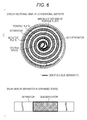
- the configuration is such that one separator for reinforcement (sub-separator) is provided in a central portion of a separator in an expanded state (refer to a lower drawing of Fig. 6 ), and that the sub-separator is located both on the radially inner side of the winding-start end of the positive electrode plate and on the radially outer side of the winding-start end in a state wound spirally (refer to an upper drawing of Fig. 6 ).
- the separator for reinforcement is located inside a central space of the spiral electrode group, and this section is a wasteful section that does not contribute to short circuit prevention. The short circuit cannot be prevented unless the large amount of separator for reinforcement is used.
- An object of the present invention is to efficiently prevent a short circuit with reduced reinforced portions.
- An energy storage device includes a spiral electrode group in which a first electrode plate and a second electrode plate having polarity reverse to that of the first electrode plate are spirally wound with a separator interposed therebetween, wherein the second electrode plate is opposed to an inner circumference and an outer circumference of the first electrode plate, portions of the separator are reinforced, the reinforced portions of the separator include a first reinforced portion formed between a winding-start end of the first electrode plate and the second electrode plate located on a radially outer side of the winding-start end, and a second reinforced portion formed between the winding-start end of the first electrode plate and the second electrode plate located on a radially inner side of the winding-start end, and the first reinforced portion and the second reinforced portion are arranged apart from each other.
- An energy storage device includes a spiral electrode group in which a first electrode plate and a second electrode plate having polarity reverse to that of the first electrode plate are spirally wound with a separator interposed therebetween, wherein the second electrode plate is opposed to an inner circumference and an outer circumference of the first electrode plate, portions of the separator are reinforced, the reinforced portions of the separator include a first reinforced portion formed between a winding-start end of the first electrode plate and the second electrode plate located on a radially outer side of the winding-start end, and a second reinforced portion formed between the winding-start end of the first electrode plate and the second electrode plate located on a radially inner side of the winding-start end, and the first reinforced portion and the second reinforced portion are arranged apart from each other.
- the second electrode plate is arranged in the inner circumference and the outer circumference of the first electrode plate, a section not involved with charge-discharge is prevented from being formed in the first electrode plate, so that the energy storage device with a high energy density can be manufactured by utilizing a charge-discharge capacity of the first electrode plate to the maximum.
- the second electrode plate is opposed to the inner circumference and the outer circumference of the first electrode plate, and strength in a separator region where the first electrode plate and the second electrode plate are opposed (the separator region of only a section where a short circuit easily occurs) is increased, which can prevent the separator from being damaged, and can efficiently prevent the short circuit.
- the spiral electrode group has a central space, that the separator opposed to neither the first electrode plate nor the second electrode plate is arranged in the central space, and that the separator arranged in the central space includes a non-reinforced portion where reinforced portions which are reinforced are not formed.
- the above-described configuration enables the separator to be wound in a state fixed to a winding shaft such as a winding core in the central space even when the one belt-like separator is used, thereby enabling the spiral electrode group to be easily manufactured. Moreover, since the section on the winding-start side with respect to the respective reinforced portions in the separator is located inside the central space of the spiral electrode group, and this section does not have the reinforced portion, the placement sections of the reinforced portions are reduced, which can exert an effect of short circuit prevention more efficiently.
- the reinforced portions which are reinforced are wound at least once.
- the above-described configuration enables position displacement between the reinforced portions and the winding-start end of the positive electrode plate at the time of manufacturing to be permitted. Moreover, since an area of the reinforced portions can be increased, the short circuit can be further prevented.
- the first electrode plate comprises an active material containing nickel oxide
- the second electrode plate comprises an active material containing a hydrogen storage alloy
- the reinforced portions are arranged, in each of which the strength of the separator region where the first electrode plate and the second electrode plate having polarity reverse to that of the first electrode plate are opposed (the separator region of only the sections where the short circuit easily occurs) is increased, only the sections contributing to the short circuit prevention are reinforced, which can reduce a wasteful reinforced portion, and can efficiently prevent the short circuit.
- an energy storage device 100 of the present embodiment is a cylindrical energy storage device in which a spiral electrode group 5 resulting from spirally winding a belt-like positive electrode plate 2 and a belt-like negative electrode plate 3 with a belt-like separator 4 interposed therebetween is contained in a cylindrical energy storage device case 6.
- the positive electrode plate 2 is configured by causing a positive base material such as, for example, a foaming type nickel porous body and the like to retain a positive active material containing nickel hydroxide.
- the negative electrode plate 3 is configured by applying a negative active material containing a hydrogen storage alloy to a negative base material made of, for example, a punching steel plate. That is, the energy storage device 100 of the present embodiment is a nickel metal hydride battery in which a discharge capacity of the positive electrode plate 2 defines an energy storage device capacity.
- the spiral electrode group 5 of the present embodiment is configured by spirally winding a layered body resulting from layering the separator 4 and the negative electrode plate 3 with the negative electrode plate 3 sandwiched by the separator 4 folded into two, and further layering the positive electrode plate 2 on one of outer surfaces of the separator 4.
- this energy storage device 100 is configured such that the negative electrode plate 3 is arranged on a radially outer side of a winding-start end 2X of the positive electrode plate 2 and on a radially inner side thereof. That is, in the spiral electrode group 5, the winding-start end 2X of the positive electrode plate 2 is sandwiched by the negative electrode plate 3 from the radially outer side and the radially inner side.
- the electrode plate located on a radially innermost side of the spiral electrode group 5 is the negative electrode plate 3.
- the separator 4 has a first reinforced portion 41 formed between the winding-start end 2X of the positive electrode plate 2 and the negative electrode plate 3 located on the radially outer side of the winding-start end 2X, and a second reinforced portion 42 formed between the winding-start end 2X of the positive electrode plate 2 and the negative electrode plate 3 located on the radially inner side of the winding-start end 2X.
- These first reinforced portion 41 and the second reinforced portion 42 are wound at least once (go round), particularly as shown in Fig. 2 .
- a section of the separator 4 on the winding start side with respect to the first reinforced portion 41 and the second reinforced portion 42 is located inside a central space 5S of the spiral electrode group 5.
- the section of the separator 4 inside the central space 5S has a non-reinforced portion 43 where reinforced portions are not formed.
- This non-reinforced portion 43 is preferably formed in the substantially whole separator 4 located inside the central space 5S of the spiral electrode group 5.
- the first reinforced portion 41 makes contact with a substantially whole outer surface forming a corner portion on the radially outer side of the winding-start end 2X of the positive electrode plate 2
- the second reinforced portion 42 makes contact with a substantially whole inner surface forming a corner portion on the radially inner side of the winding-start end 2X of the positive electrode plate 2.
- These first reinforced portion 41 and second reinforced portion 42 are configured by increasing a thickness of the separator 4.
- the first reinforced portion 41 and the second reinforced portion 42 are each configured by superposing a rectangular reinforcement separator 402 on a belt-like separator body 401, for example, using welding or the like, as shown in Fig. 3 .
- a section of the separator body 401 between the two reinforcement separators 402 is the non-reinforced portion 43.
- the separator body 401 and the reinforcement separators 402 of the present embodiment are formed of a same material such as non-woven fabrics, for example, polyolefin.
- the separator body 401 and the reinforcement separators 402 may be formed of a different material from each other.
- a widthwise dimension along a central axis direction of the separator body 401 and a widthwise dimension along the central axis direction of the reinforcement separators 402 are substantially the same.
- the separator 4 configured as described above is belt-like, and in the expanded state, the rectangular first reinforced portion 41 and the rectangular second reinforced portion 42 are formed on both sides of the non-reinforced portion 43.
- the non-reinforced portion 43 includes a folding line 4L, and the first reinforced portion 41 and the second reinforced portion 42 are formed on both sides of the non-reinforced portion 43.
- the first reinforced portion 41 and the second reinforced portion 42 are formed so as to be wound at least once when the separator 4 is spirally wound.
- a formation region of the first reinforced portion 41 is longer in a longitudinal direction.
- Dimensions in the longitudinal direction of the first reinforced portion 41 and the second reinforced portion 42 may be different from each other in this manner, or may be the same.
- the reinforcement separators 402 are superposed on the separator body 401, for example, by thermal welding or the like to form the first reinforced portion 41 and the second reinforced portion 42 in the separator 4. These sections where these reinforcement separators 402 are superposed are the first reinforced portion 41 and the second reinforced portion 42.
- the non-reinforced portion 43 formed between the first reinforced portion 41 and the second reinforced portion 42 is folded into two, and the negative electrode plate 3 is sandwiched by the separator 4 folded into two.
- the positive electrode plate 2 is layered on one of the outer surfaces (the upper surface) of the separator 4. While in Fig. 4 , the layered body is folded such that the two reinforced portions 41, 42 are arranged inside, the layered body may be folded such that the reinforced portions 41, 42 are arranged outside.
- the layered body is wound, using a winding core 7.
- the winding direction of the present embodiment is a direction in which the winding core 7 rotates on an upper side of the layered body toward the positive electrode plate 2 side (a clockwise direction in Fig. 4 ).
- the specific winding method after only the separator 4 is wound around the winding core 7 at least about once, only the negative electrode plate 3 is wound at least about once together with the separator 4. Thereafter, the negative electrode plate 3 and the positive electrode plate 2 are spirally wound together with the separator 4 while being rolled around the winding core 7.
- winding only the negative electrode plate 3 at least once together with the separator 4 allows the negative electrode plate 2 to be located on the radially inner side of the winding-start end 2X of the positive electrode plate 2.
- the winding core 7 is pulled and removed, by which the spiral electrode group 5 is formed.
- the negative electrode plate 3 need not be wound once.
- the negative electrode plate 3 is arranged on the radially outer side of the winding-start end 2X of the positive electrode plate 2 and on the radially inner side thereof, a section not involved with the charge-discharge is prevented from being formed in the positive electrode plate 2, which can sufficiently assure a battery capacity.
- the nickel metal hydride battery in which the discharge capacity of the positive electrode plate 2 regulates the battery capacity, is used, so that the effect of the present embodiment becomes more remarkable.
- the first reinforced portion 41 is located between a corner portion on the radially inner side of the winding-start end 2X of the positive electrode plate 2, and the negative electrode plate 3, and the second reinforced portion 42 is located between a corner portion on the radially outer side of the winding-start end 2X of the positive electrode plate 2, and the negative electrode plate 3, which can prevent the two inner and outer corner portions of the winding-start end 2X of the positive electrode plate 2 from tearing the separator 4, thereby preventing a short circuit.
- a volume of the separator 4 occupying the central space 5S of the spiral electrode group 5 can be made smaller, and a residual space inside the energy storage device 100 can be increased, which can increase a capacity of an electrolyte solution.
- the non-reinforced portion 43 includes the folding line 4L, and the first reinforced portion 41 and the second reinforced portion 42 are formed on both sides of the non-reinforced portion 43, the spiral electrode group 5 can be configured by the one separator 4, so that a parts count can be reduced, and winding work can be made easier.
- the folding line 4L is included in the non-reinforced portion 43, which can make it easier to fold the separator 4 into two.
- first reinforced portion 41 and the second reinforced portion 42 are wound at least once, positional displacement between the respective reinforced portions 41, 42, and the winding-start end 2X of the positive electrode plate 2 at the time of manufacturing can be permitted. Moreover, since areas of the respective reinforced portions 41, 42 can be increased, a short circuit can be further prevented.
- the present invention is not limited to the foregoing embodiment.
- the one separator is folded into two to configure the spiral electrode group
- a spiral electrode group resulting from sandwiching a negative electrode plate between two separators and winding the same may be employed.
- a reinforced portion may be formed in a section corresponding to a radially inner side or a radially outer side of a winding-start end of a positive electrode plate, and a winding-start end of each of the separators may have a non-reinforced portion.
- first reinforced portion 41 and the second reinforced portion 42 are configured by superposing the reinforcement separators 402 on the separator body 401
- a configuration may be employed, in which a thickness of the separator body itself is partially increased to thereby configure the first reinforced portion and the second reinforced portion, or when the separator body is non-woven fabrics, density is partially increased to thereby configure the first reinforced portion and the second reinforced portion.
- the separator may have a third reinforced portion 44 formed between a winding-finish end 2Y of the positive electrode plate 2, and the negative electrode plate 3 located on the radially outer side of the winding-finish end 2Y, and a fourth reinforced portion 45 formed between the winding-finish end 2Y of the positive electrode plate 2 and the negative electrode plate 3 located on the radially inner side of the winding-finish end 2Y.
- a configuration of these third reinforced portion 44 and fourth reinforced portion 45 are similar to that of the first reinforced portion 41 and the second reinforced portion 42.
- the present invention is applied to the cylindrical energy storage device in which the spiral electrode group is contained in a cylindrical energy storage device case
- the present invention can be applied to a prismatic energy storage device with a flat spiral electrode group, which is contained in a prismatic energy storage device case.
Landscapes
- Chemical & Material Sciences (AREA)
- Chemical Kinetics & Catalysis (AREA)
- Electrochemistry (AREA)
- General Chemical & Material Sciences (AREA)
- Engineering & Computer Science (AREA)
- Manufacturing & Machinery (AREA)
- Secondary Cells (AREA)
- Cell Separators (AREA)
- Connection Of Batteries Or Terminals (AREA)
Abstract
Description
- The present invention relates to an energy storage device with a spiral electrode group.
- Conventionally, spiral electrode groups are known in which a positive electrode plate and a negative electrode plate are wound with a separator interposed therebetween. As disclosed in
JP-A-2001-319678 - Some consumer-use nickel metal hydride batteries or the like are configured such that a negative electrode plate is arranged not only in a radially outer circumference of a positive electrode plate but in an inner circumference of a winding-start end in order to achieve high energy density by utilizing a charge-discharge capacity of a positive electrode to the maximum. An energy storage device having the above-described configuration has a problem that a short circuit is caused by a corner portion, a burr or the like not only on the radially outer side of the winding-start end of the positive electrode plate but also on the radially inner side.
- Thus, as shown in
Fig. 6 , the configuration is such that one separator for reinforcement (sub-separator) is provided in a central portion of a separator in an expanded state (refer to a lower drawing ofFig. 6 ), and that the sub-separator is located both on the radially inner side of the winding-start end of the positive electrode plate and on the radially outer side of the winding-start end in a state wound spirally (refer to an upper drawing ofFig. 6 ). - According to the above-described configuration, the separator for reinforcement is located inside a central space of the spiral electrode group, and this section is a wasteful section that does not contribute to short circuit prevention. The short circuit cannot be prevented unless the large amount of separator for reinforcement is used.
- An object of the present invention is to efficiently prevent a short circuit with reduced reinforced portions.
- An energy storage device according to an aspect of the present invention includes a spiral electrode group in which a first electrode plate and a second electrode plate having polarity reverse to that of the first electrode plate are spirally wound with a separator interposed therebetween, wherein the second electrode plate is opposed to an inner circumference and an outer circumference of the first electrode plate, portions of the separator are reinforced, the reinforced portions of the separator include a first reinforced portion formed between a winding-start end of the first electrode plate and the second electrode plate located on a radially outer side of the winding-start end, and a second reinforced portion formed between the winding-start end of the first electrode plate and the second electrode plate located on a radially inner side of the winding-start end, and the first reinforced portion and the second reinforced portion are arranged apart from each other.
-
-
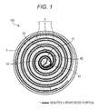
Fig. 1 shows a cross-sectional view of an energy storage device of an embodiment; -
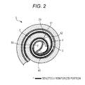
Fig. 2 shows a partially-enlarged cross-sectional view mainly illustrating a winding-start end of a positive electrode plate of the embodiment; -
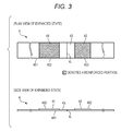
Fig. 3 shows a plan view and a side view of a separator in an expanded state of the embodiment; -
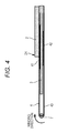
Fig. 4 shows a schematic view illustrating a manufacturing method of a spiral electrode group of the embodiment; -
Fig. 5 shows a cross-sectional view of an energy storage device of a modification; and -
Fig. 6 shows a cross-sectional view of a conventional energy storage device having a spiral electrode group, and an expanded view of a separator therein. - An energy storage device according to an aspect of the present invention includes a spiral electrode group in which a first electrode plate and a second electrode plate having polarity reverse to that of the first electrode plate are spirally wound with a separator interposed therebetween, wherein the second electrode plate is opposed to an inner circumference and an outer circumference of the first electrode plate, portions of the separator are reinforced, the reinforced portions of the separator include a first reinforced portion formed between a winding-start end of the first electrode plate and the second electrode plate located on a radially outer side of the winding-start end, and a second reinforced portion formed between the winding-start end of the first electrode plate and the second electrode plate located on a radially inner side of the winding-start end, and the first reinforced portion and the second reinforced portion are arranged apart from each other.
- In the above-described energy storage device, since the second electrode plate is arranged in the inner circumference and the outer circumference of the first electrode plate, a section not involved with charge-discharge is prevented from being formed in the first electrode plate, so that the energy storage device with a high energy density can be manufactured by utilizing a charge-discharge capacity of the first electrode plate to the maximum.
- Moreover, the second electrode plate is opposed to the inner circumference and the outer circumference of the first electrode plate, and strength in a separator region where the first electrode plate and the second electrode plate are opposed (the separator region of only a section where a short circuit easily occurs) is increased, which can prevent the separator from being damaged, and can efficiently prevent the short circuit.
- It is preferable that the spiral electrode group has a central space, that the separator opposed to neither the first electrode plate nor the second electrode plate is arranged in the central space, and that the separator arranged in the central space includes a non-reinforced portion where reinforced portions which are reinforced are not formed.
- The above-described configuration enables the separator to be wound in a state fixed to a winding shaft such as a winding core in the central space even when the one belt-like separator is used, thereby enabling the spiral electrode group to be easily manufactured. Moreover, since the section on the winding-start side with respect to the respective reinforced portions in the separator is located inside the central space of the spiral electrode group, and this section does not have the reinforced portion, the placement sections of the reinforced portions are reduced, which can exert an effect of short circuit prevention more efficiently.
- It is preferable that the reinforced portions which are reinforced are wound at least once.
- The above-described configuration enables position displacement between the reinforced portions and the winding-start end of the positive electrode plate at the time of manufacturing to be permitted. Moreover, since an area of the reinforced portions can be increased, the short circuit can be further prevented.
- Moreover, it is preferable that in an energy storage device, the first electrode plate comprises an active material containing nickel oxide, and the second electrode plate comprises an active material containing a hydrogen storage alloy.
- According to the above-described configuration, since the reinforced portions are arranged, in each of which the strength of the separator region where the first electrode plate and the second electrode plate having polarity reverse to that of the first electrode plate are opposed (the separator region of only the sections where the short circuit easily occurs) is increased, only the sections contributing to the short circuit prevention are reinforced, which can reduce a wasteful reinforced portion, and can efficiently prevent the short circuit.
- Hereinafter, one embodiment of the present invention will be described with reference to the drawings.
- As shown in
Fig. 1 , anenergy storage device 100 of the present embodiment is a cylindrical energy storage device in which aspiral electrode group 5 resulting from spirally winding a belt-likepositive electrode plate 2 and a belt-likenegative electrode plate 3 with a belt-like separator 4 interposed therebetween is contained in a cylindrical energystorage device case 6. - Specifically, the
positive electrode plate 2 is configured by causing a positive base material such as, for example, a foaming type nickel porous body and the like to retain a positive active material containing nickel hydroxide. Moreover, thenegative electrode plate 3 is configured by applying a negative active material containing a hydrogen storage alloy to a negative base material made of, for example, a punching steel plate. That is, theenergy storage device 100 of the present embodiment is a nickel metal hydride battery in which a discharge capacity of thepositive electrode plate 2 defines an energy storage device capacity. - The
spiral electrode group 5 of the present embodiment is configured by spirally winding a layered body resulting from layering theseparator 4 and thenegative electrode plate 3 with thenegative electrode plate 3 sandwiched by theseparator 4 folded into two, and further layering thepositive electrode plate 2 on one of outer surfaces of theseparator 4. - As shown in
Figs. 1 and2 , thisenergy storage device 100 is configured such that thenegative electrode plate 3 is arranged on a radially outer side of a winding-start end 2X of thepositive electrode plate 2 and on a radially inner side thereof. That is, in thespiral electrode group 5, the winding-start end 2X of thepositive electrode plate 2 is sandwiched by thenegative electrode plate 3 from the radially outer side and the radially inner side. The electrode plate located on a radially innermost side of thespiral electrode group 5 is thenegative electrode plate 3. - In this configuration, as shown in
Figs. 1 and2 , theseparator 4 has a first reinforcedportion 41 formed between the winding-start end 2X of thepositive electrode plate 2 and thenegative electrode plate 3 located on the radially outer side of the winding-start end 2X, and a second reinforcedportion 42 formed between the winding-start end 2X of thepositive electrode plate 2 and thenegative electrode plate 3 located on the radially inner side of the winding-start end 2X. These first reinforcedportion 41 and the second reinforcedportion 42 are wound at least once (go round), particularly as shown inFig. 2 . - As shown in
Figs. 1 and2 , a section of theseparator 4 on the winding start side with respect to the first reinforcedportion 41 and the second reinforcedportion 42 is located inside acentral space 5S of thespiral electrode group 5. The section of theseparator 4 inside thecentral space 5S has anon-reinforced portion 43 where reinforced portions are not formed. Thisnon-reinforced portion 43 is preferably formed in the substantiallywhole separator 4 located inside thecentral space 5S of thespiral electrode group 5. - The first reinforced
portion 41 makes contact with a substantially whole outer surface forming a corner portion on the radially outer side of the winding-start end 2X of thepositive electrode plate 2, and the second reinforcedportion 42 makes contact with a substantially whole inner surface forming a corner portion on the radially inner side of the winding-start end 2X of thepositive electrode plate 2. These first reinforcedportion 41 and second reinforcedportion 42 are configured by increasing a thickness of theseparator 4. Specifically, the first reinforcedportion 41 and the second reinforcedportion 42 are each configured by superposing arectangular reinforcement separator 402 on a belt-like separator body 401, for example, using welding or the like, as shown inFig. 3 . A section of theseparator body 401 between the tworeinforcement separators 402 is thenon-reinforced portion 43. - The
separator body 401 and thereinforcement separators 402 of the present embodiment are formed of a same material such as non-woven fabrics, for example, polyolefin. Theseparator body 401 and thereinforcement separators 402 may be formed of a different material from each other. A widthwise dimension along a central axis direction of theseparator body 401 and a widthwise dimension along the central axis direction of thereinforcement separators 402 are substantially the same. - As shown in
Fig. 3 , theseparator 4 configured as described above is belt-like, and in the expanded state, the rectangular first reinforcedportion 41 and the rectangular second reinforcedportion 42 are formed on both sides of the non-reinforcedportion 43. In a state where theseparator 4 is expanded, thenon-reinforced portion 43 includes afolding line 4L, and the first reinforcedportion 41 and the second reinforcedportion 42 are formed on both sides of the non-reinforcedportion 43. The first reinforcedportion 41 and the second reinforcedportion 42 are formed so as to be wound at least once when theseparator 4 is spirally wound. Since a radius of curvature of the first reinforcedportion 41 is larger than a radius of curvature of the second reinforcedportion 42, in the present embodiment, a formation region of the first reinforcedportion 41 is longer in a longitudinal direction. Dimensions in the longitudinal direction of the first reinforcedportion 41 and the second reinforcedportion 42 may be different from each other in this manner, or may be the same. - Next, a manufacturing method of the
spiral electrode group 5 configured as described above will be described with reference toFig. 4 . - First, the
reinforcement separators 402 are superposed on theseparator body 401, for example, by thermal welding or the like to form the first reinforcedportion 41 and the second reinforcedportion 42 in theseparator 4. These sections where thesereinforcement separators 402 are superposed are the first reinforcedportion 41 and the second reinforcedportion 42. - Next, the
non-reinforced portion 43 formed between the first reinforcedportion 41 and the second reinforcedportion 42 is folded into two, and thenegative electrode plate 3 is sandwiched by theseparator 4 folded into two. Thepositive electrode plate 2 is layered on one of the outer surfaces (the upper surface) of theseparator 4. While inFig. 4 , the layered body is folded such that the two reinforcedportions portions - The layered body is wound, using a winding
core 7. As shown inFig. 4 , the winding direction of the present embodiment is a direction in which the windingcore 7 rotates on an upper side of the layered body toward thepositive electrode plate 2 side (a clockwise direction inFig. 4 ). As the specific winding method, after only theseparator 4 is wound around the windingcore 7 at least about once, only thenegative electrode plate 3 is wound at least about once together with theseparator 4. Thereafter, thenegative electrode plate 3 and thepositive electrode plate 2 are spirally wound together with theseparator 4 while being rolled around the windingcore 7. In this manner, winding only thenegative electrode plate 3 at least once together with theseparator 4 allows thenegative electrode plate 2 to be located on the radially inner side of the winding-start end 2X of thepositive electrode plate 2. After the winding, the windingcore 7 is pulled and removed, by which thespiral electrode group 5 is formed. - When the winding direction by the winding
core 7 is reverse, that is, when the winding core rotates in a direction in which the winding core rotates on a lower side of the layered body toward the opposite side of the positive electrode plate 2 (in a counterclockwise direction), thenegative electrode plate 3 need not be wound once. - According to the
energy storage device 100 according to the present embodiment configured as described above, since thenegative electrode plate 3 is arranged on the radially outer side of the winding-start end 2X of thepositive electrode plate 2 and on the radially inner side thereof, a section not involved with the charge-discharge is prevented from being formed in thepositive electrode plate 2, which can sufficiently assure a battery capacity. Particularly, in the present embodiment, the nickel metal hydride battery, in which the discharge capacity of thepositive electrode plate 2 regulates the battery capacity, is used, so that the effect of the present embodiment becomes more remarkable. - The first reinforced
portion 41 is located between a corner portion on the radially inner side of the winding-start end 2X of thepositive electrode plate 2, and thenegative electrode plate 3, and the second reinforcedportion 42 is located between a corner portion on the radially outer side of the winding-start end 2X of thepositive electrode plate 2, and thenegative electrode plate 3, which can prevent the two inner and outer corner portions of the winding-start end 2X of thepositive electrode plate 2 from tearing theseparator 4, thereby preventing a short circuit. - Furthermore, since the section of the
separator 4 on the winding-start side with respect to the reinforcedportions central space 5S of thespiral electrode group 5, and this section has thenon-reinforced portion 43 where the reinforced portions are not formed, a volume of theseparator 4 occupying thecentral space 5S of thespiral electrode group 5 can be made smaller, and a residual space inside theenergy storage device 100 can be increased, which can increase a capacity of an electrolyte solution. - In addition, since in the state where the
separator 4 is expanded, thenon-reinforced portion 43 includes thefolding line 4L, and the first reinforcedportion 41 and the second reinforcedportion 42 are formed on both sides of thenon-reinforced portion 43, thespiral electrode group 5 can be configured by the oneseparator 4, so that a parts count can be reduced, and winding work can be made easier. Particularly, thefolding line 4L is included in thenon-reinforced portion 43, which can make it easier to fold theseparator 4 into two. - Additionally, since the first reinforced
portion 41 and the second reinforcedportion 42 are wound at least once, positional displacement between the respective reinforcedportions start end 2X of thepositive electrode plate 2 at the time of manufacturing can be permitted. Moreover, since areas of the respective reinforcedportions - The present invention is not limited to the foregoing embodiment.
- For example, while in the foregoing embodiment, the one separator is folded into two to configure the spiral electrode group, a spiral electrode group resulting from sandwiching a negative electrode plate between two separators and winding the same may be employed. In this case, in each of the separators, a reinforced portion may be formed in a section corresponding to a radially inner side or a radially outer side of a winding-start end of a positive electrode plate, and a winding-start end of each of the separators may have a non-reinforced portion.
- Moreover, in addition to the configuration in which the first reinforced
portion 41 and the second reinforcedportion 42 are configured by superposing thereinforcement separators 402 on theseparator body 401, a configuration may be employed, in which a thickness of the separator body itself is partially increased to thereby configure the first reinforced portion and the second reinforced portion, or when the separator body is non-woven fabrics, density is partially increased to thereby configure the first reinforced portion and the second reinforced portion. - Furthermore, as shown in
Fig. 5 , in addition to the first reinforcedportion 41 and the second reinforcedportion 42, the separator may have a third reinforcedportion 44 formed between a winding-finish end 2Y of thepositive electrode plate 2, and thenegative electrode plate 3 located on the radially outer side of the winding-finish end 2Y, and a fourth reinforcedportion 45 formed between the winding-finish end 2Y of thepositive electrode plate 2 and thenegative electrode plate 3 located on the radially inner side of the winding-finish end 2Y. A configuration of these third reinforcedportion 44 and fourth reinforcedportion 45 are similar to that of the first reinforcedportion 41 and the second reinforcedportion 42. - Besides, while in the foregoing embodiment, the present invention is applied to the cylindrical energy storage device in which the spiral electrode group is contained in a cylindrical energy storage device case, the present invention can be applied to a prismatic energy storage device with a flat spiral electrode group, which is contained in a prismatic energy storage device case.
- In addition, it goes without saying that the present invention is not limited to the foregoing embodiments, and that various modifications can be made within a range not departing from the gist.
Claims (4)
- An energy storage device comprising a spiral electrode group in which a first electrode plate and a second electrode plate having polarity reverse to that of the first electrode plate are spirally wound with a separator interposed therebetween, wherein
the second electrode plate is opposed to an inner circumference and an outer circumference of the first electrode plate,
portions of the separator are reinforced,
the reinforced portions of the separator include a first reinforced portion formed between a winding-start end of the first electrode plate and the second electrode plate located on a radially outer side of the winding-start end, and a second reinforced portion formed between the winding-start end of the first electrode plate and the second electrode plate located on a radially inner side of the winding-start end, and
the first reinforced portion and the second reinforced portion are arranged apart from each other. - The energy storage device according to claim 1, wherein
the spiral electrode group has a central space,
the separator opposed to neither the first electrode plate nor the second electrode plate is arranged in the central space, and
the separator arranged in the central space includes a non-reinforced portion where reinforced portions which are reinforced are not formed. - The energy storage device according to claim 1 or claim 2, wherein the reinforced portions which are reinforced are wound at least once.
- The energy storage device according to any one of claims 1 to 3, wherein
the first electrode plate comprises an active material containing nickel oxide, and
the second electrode plate comprises an active material containing a hydrogen storage alloy.
Applications Claiming Priority (1)
| Application Number | Priority Date | Filing Date | Title |
|---|---|---|---|
| JP2013094495A JP6094807B2 (en) | 2013-04-26 | 2013-04-26 | Battery with spiral electrode group |
Publications (2)
| Publication Number | Publication Date |
|---|---|
| EP2797139A1 true EP2797139A1 (en) | 2014-10-29 |
| EP2797139B1 EP2797139B1 (en) | 2017-06-07 |
Family
ID=50677940
Family Applications (1)
| Application Number | Title | Priority Date | Filing Date |
|---|---|---|---|
| EP14165996.1A Active EP2797139B1 (en) | 2013-04-26 | 2014-04-25 | Energy storage device with spiral electrode group |
Country Status (4)
| Country | Link |
|---|---|
| US (1) | US9608247B2 (en) |
| EP (1) | EP2797139B1 (en) |
| JP (1) | JP6094807B2 (en) |
| CN (1) | CN104124478B (en) |
Cited By (3)
| Publication number | Priority date | Publication date | Assignee | Title |
|---|---|---|---|---|
| GB2576741A (en) * | 2018-08-29 | 2020-03-04 | Qiu Fulian | Inductive chargeable energy storage device |
| EP4369463A4 (en) * | 2021-12-13 | 2025-06-04 | Contemporary Amperex Technology (Hong Kong) Limited | ELECTRODE ASSEMBLY, BATTERY CELL, BATTERY AND ELECTRICAL DEVICE |
| EP4525109A4 (en) * | 2022-07-19 | 2026-02-11 | Lg Energy Solution Ltd | CYLINDRICAL BATTERY, BATTERY PACK AND VEHICLE |
Families Citing this family (5)
| Publication number | Priority date | Publication date | Assignee | Title |
|---|---|---|---|---|
| JP6474329B2 (en) * | 2015-07-16 | 2019-02-27 | 日立オートモティブシステムズ株式会社 | Secondary battery |
| JP2019016423A (en) * | 2015-11-27 | 2019-01-31 | パナソニックIpマネジメント株式会社 | Cylindrical battery |
| EP3605697B1 (en) * | 2018-07-31 | 2025-04-23 | VARTA Microbattery GmbH | Method for producing an electrode separator coil, electrode separator coil and button cell comprising such a coil |
| CN115799656B (en) * | 2021-09-10 | 2023-12-15 | 宁德时代新能源科技股份有限公司 | Electrode assembly, battery cell, battery, device and manufacturing method related to electrode assembly |
| JPWO2023190872A1 (en) | 2022-03-31 | 2023-10-05 |
Citations (4)
| Publication number | Priority date | Publication date | Assignee | Title |
|---|---|---|---|---|
| US3298871A (en) * | 1963-08-02 | 1967-01-17 | Accumulateurs Fixes | Electric cells with spiral wound electrodes |
| JPS61273874A (en) * | 1985-05-28 | 1986-12-04 | Shin Kobe Electric Mach Co Ltd | Manufacture of vortical electrode |
| JP2001319678A (en) | 2000-05-10 | 2001-11-16 | Toshiba Battery Co Ltd | Winding type electrode manufacturing apparatus |
| JP2002319429A (en) * | 2001-04-20 | 2002-10-31 | Hitachi Maxell Ltd | Alkaline storage battery |
Family Cites Families (9)
| Publication number | Priority date | Publication date | Assignee | Title |
|---|---|---|---|---|
| JP2973540B2 (en) * | 1991-02-21 | 1999-11-08 | 新神戸電機株式会社 | Method of manufacturing spiral electrode group for alkaline storage battery |
| US5849430A (en) * | 1995-05-31 | 1998-12-15 | Samsung Display Devices Co., Ltd. | Structure of an electrode of a secondary battery |
| KR960043320A (en) * | 1995-05-31 | 1996-12-23 | 윤종용 | Method for manufacturing current collector for secondary battery and pole plate |
| JPH0963635A (en) * | 1995-08-29 | 1997-03-07 | Toshiba Battery Co Ltd | Alkaline secondary battery |
| JPH09147846A (en) | 1995-11-24 | 1997-06-06 | Shin Kobe Electric Mach Co Ltd | Swirl electrode body for cylindrical sealed alkaline storage battery |
| JP2000113902A (en) * | 1998-10-06 | 2000-04-21 | Toshiba Battery Co Ltd | Alkaline secondary battery |
| JP2000285956A (en) * | 1999-03-30 | 2000-10-13 | Sanyo Electric Co Ltd | Cylindrical alkaline storage battery |
| JP2003208883A (en) | 2002-01-11 | 2003-07-25 | Sanyo Electric Co Ltd | Battery |
| JP2008146969A (en) | 2006-12-08 | 2008-06-26 | Matsushita Electric Ind Co Ltd | Organic electrolyte battery |
-
2013
- 2013-04-26 JP JP2013094495A patent/JP6094807B2/en active Active
-
2014
- 2014-04-16 CN CN201410153056.0A patent/CN104124478B/en active Active
- 2014-04-23 US US14/259,673 patent/US9608247B2/en active Active
- 2014-04-25 EP EP14165996.1A patent/EP2797139B1/en active Active
Patent Citations (4)
| Publication number | Priority date | Publication date | Assignee | Title |
|---|---|---|---|---|
| US3298871A (en) * | 1963-08-02 | 1967-01-17 | Accumulateurs Fixes | Electric cells with spiral wound electrodes |
| JPS61273874A (en) * | 1985-05-28 | 1986-12-04 | Shin Kobe Electric Mach Co Ltd | Manufacture of vortical electrode |
| JP2001319678A (en) | 2000-05-10 | 2001-11-16 | Toshiba Battery Co Ltd | Winding type electrode manufacturing apparatus |
| JP2002319429A (en) * | 2001-04-20 | 2002-10-31 | Hitachi Maxell Ltd | Alkaline storage battery |
Cited By (3)
| Publication number | Priority date | Publication date | Assignee | Title |
|---|---|---|---|---|
| GB2576741A (en) * | 2018-08-29 | 2020-03-04 | Qiu Fulian | Inductive chargeable energy storage device |
| EP4369463A4 (en) * | 2021-12-13 | 2025-06-04 | Contemporary Amperex Technology (Hong Kong) Limited | ELECTRODE ASSEMBLY, BATTERY CELL, BATTERY AND ELECTRICAL DEVICE |
| EP4525109A4 (en) * | 2022-07-19 | 2026-02-11 | Lg Energy Solution Ltd | CYLINDRICAL BATTERY, BATTERY PACK AND VEHICLE |
Also Published As
| Publication number | Publication date |
|---|---|
| JP6094807B2 (en) | 2017-03-15 |
| JP2014216261A (en) | 2014-11-17 |
| US20140322577A1 (en) | 2014-10-30 |
| CN104124478B (en) | 2018-09-25 |
| EP2797139B1 (en) | 2017-06-07 |
| US9608247B2 (en) | 2017-03-28 |
| CN104124478A (en) | 2014-10-29 |
Similar Documents
| Publication | Publication Date | Title |
|---|---|---|
| EP2797139B1 (en) | Energy storage device with spiral electrode group | |
| CN110337752B (en) | Nonaqueous electrolyte secondary battery | |
| JP6486801B2 (en) | Secondary battery | |
| WO2018061381A1 (en) | Non-aqueous electrolyte secondary battery | |
| WO2012133233A1 (en) | Cylindrical battery and electrode structure for battery | |
| US20140349158A1 (en) | Cylindrical battery | |
| JPWO2017077698A1 (en) | Electrode plate for power storage device and power storage device | |
| JP2022152423A (en) | cylindrical battery | |
| JP2017084680A (en) | Power storage element | |
| JP2005056674A (en) | Cylindrical alkaline battery | |
| WO2017090219A1 (en) | Cylindrical battery | |
| JP7225111B2 (en) | Method for manufacturing non-aqueous electrolyte secondary battery | |
| JP5439448B2 (en) | Lithium ion secondary battery | |
| JP4928827B2 (en) | battery | |
| US20250015360A1 (en) | Cylindrical secondary battery | |
| JP4159296B2 (en) | Rectangular spiral electrode group and prismatic nonaqueous electrolyte battery using the same | |
| JP4359099B2 (en) | Cylindrical alkaline storage battery | |
| JP2017130439A (en) | Negative electrode plate, energy storage element, method for manufacturing negative electrode plate, and method for manufacturing energy storage element | |
| JP2016066535A (en) | Power storage element and manufacturing method of power storage element | |
| JP2016149300A (en) | Alkaline secondary battery | |
| EP4661194A1 (en) | Cylindrical nonaqueous electrolyte secondary battery | |
| EP4661147A1 (en) | Cylindrical non-aqueous electrolyte secondary battery | |
| WO2026094417A1 (en) | Cylindrical battery | |
| WO2024181045A1 (en) | Secondary battery | |
| JP2021044100A (en) | Electrochemical cell |
Legal Events
| Date | Code | Title | Description |
|---|---|---|---|
| PUAI | Public reference made under article 153(3) epc to a published international application that has entered the european phase |
Free format text: ORIGINAL CODE: 0009012 |
|
| 17P | Request for examination filed |
Effective date: 20140425 |
|
| AK | Designated contracting states |
Kind code of ref document: A1 Designated state(s): AL AT BE BG CH CY CZ DE DK EE ES FI FR GB GR HR HU IE IS IT LI LT LU LV MC MK MT NL NO PL PT RO RS SE SI SK SM TR |
|
| AX | Request for extension of the european patent |
Extension state: BA ME |
|
| R17P | Request for examination filed (corrected) |
Effective date: 20150416 |
|
| RBV | Designated contracting states (corrected) |
Designated state(s): AL AT BE BG CH CY CZ DE DK EE ES FI FR GB GR HR HU IE IS IT LI LT LU LV MC MK MT NL NO PL PT RO RS SE SI SK SM TR |
|
| 17Q | First examination report despatched |
Effective date: 20160801 |
|
| STAA | Information on the status of an ep patent application or granted ep patent |
Free format text: STATUS: EXAMINATION IS IN PROGRESS |
|
| GRAP | Despatch of communication of intention to grant a patent |
Free format text: ORIGINAL CODE: EPIDOSNIGR1 |
|
| STAA | Information on the status of an ep patent application or granted ep patent |
Free format text: STATUS: GRANT OF PATENT IS INTENDED |
|
| GRAJ | Information related to disapproval of communication of intention to grant by the applicant or resumption of examination proceedings by the epo deleted |
Free format text: ORIGINAL CODE: EPIDOSDIGR1 |
|
| GRAP | Despatch of communication of intention to grant a patent |
Free format text: ORIGINAL CODE: EPIDOSNIGR1 |
|
| INTG | Intention to grant announced |
Effective date: 20170105 |
|
| GRAJ | Information related to disapproval of communication of intention to grant by the applicant or resumption of examination proceedings by the epo deleted |
Free format text: ORIGINAL CODE: EPIDOSDIGR1 |
|
| GRAP | Despatch of communication of intention to grant a patent |
Free format text: ORIGINAL CODE: EPIDOSNIGR1 |
|
| INTG | Intention to grant announced |
Effective date: 20170116 |
|
| INTG | Intention to grant announced |
Effective date: 20170203 |
|
| GRAS | Grant fee paid |
Free format text: ORIGINAL CODE: EPIDOSNIGR3 |
|
| AK | Designated contracting states |
Kind code of ref document: B1 Designated state(s): AL AT BE BG CH CY CZ DE DK EE ES FI FR GB GR HR HU IE IS IT LI LT LU LV MC MK MT NL NO PL PT RO RS SE SI SK SM TR |
|
| REG | Reference to a national code |
Ref country code: GB Ref legal event code: FG4D |
|
| GRAA | (expected) grant |
Free format text: ORIGINAL CODE: 0009210 |
|
| REG | Reference to a national code |
Ref country code: CH Ref legal event code: EP Ref country code: AT Ref legal event code: REF Ref document number: 899827 Country of ref document: AT Kind code of ref document: T Effective date: 20170615 |
|
| STAA | Information on the status of an ep patent application or granted ep patent |
Free format text: STATUS: THE PATENT HAS BEEN GRANTED |
|
| REG | Reference to a national code |
Ref country code: IE Ref legal event code: FG4D |
|
| REG | Reference to a national code |
Ref country code: DE Ref legal event code: R096 Ref document number: 602014010439 Country of ref document: DE |
|
| REG | Reference to a national code |
Ref country code: NL Ref legal event code: MP Effective date: 20170607 |
|
| REG | Reference to a national code |
Ref country code: LT Ref legal event code: MG4D |
|
| PG25 | Lapsed in a contracting state [announced via postgrant information from national office to epo] |
Ref country code: FI Free format text: LAPSE BECAUSE OF FAILURE TO SUBMIT A TRANSLATION OF THE DESCRIPTION OR TO PAY THE FEE WITHIN THE PRESCRIBED TIME-LIMIT Effective date: 20170607 Ref country code: HR Free format text: LAPSE BECAUSE OF FAILURE TO SUBMIT A TRANSLATION OF THE DESCRIPTION OR TO PAY THE FEE WITHIN THE PRESCRIBED TIME-LIMIT Effective date: 20170607 Ref country code: NO Free format text: LAPSE BECAUSE OF FAILURE TO SUBMIT A TRANSLATION OF THE DESCRIPTION OR TO PAY THE FEE WITHIN THE PRESCRIBED TIME-LIMIT Effective date: 20170907 Ref country code: GR Free format text: LAPSE BECAUSE OF FAILURE TO SUBMIT A TRANSLATION OF THE DESCRIPTION OR TO PAY THE FEE WITHIN THE PRESCRIBED TIME-LIMIT Effective date: 20170908 Ref country code: LT Free format text: LAPSE BECAUSE OF FAILURE TO SUBMIT A TRANSLATION OF THE DESCRIPTION OR TO PAY THE FEE WITHIN THE PRESCRIBED TIME-LIMIT Effective date: 20170607 Ref country code: ES Free format text: LAPSE BECAUSE OF FAILURE TO SUBMIT A TRANSLATION OF THE DESCRIPTION OR TO PAY THE FEE WITHIN THE PRESCRIBED TIME-LIMIT Effective date: 20170607 |
|
| REG | Reference to a national code |
Ref country code: AT Ref legal event code: MK05 Ref document number: 899827 Country of ref document: AT Kind code of ref document: T Effective date: 20170607 |
|
| PG25 | Lapsed in a contracting state [announced via postgrant information from national office to epo] |
Ref country code: SE Free format text: LAPSE BECAUSE OF FAILURE TO SUBMIT A TRANSLATION OF THE DESCRIPTION OR TO PAY THE FEE WITHIN THE PRESCRIBED TIME-LIMIT Effective date: 20170607 Ref country code: RS Free format text: LAPSE BECAUSE OF FAILURE TO SUBMIT A TRANSLATION OF THE DESCRIPTION OR TO PAY THE FEE WITHIN THE PRESCRIBED TIME-LIMIT Effective date: 20170607 Ref country code: NL Free format text: LAPSE BECAUSE OF FAILURE TO SUBMIT A TRANSLATION OF THE DESCRIPTION OR TO PAY THE FEE WITHIN THE PRESCRIBED TIME-LIMIT Effective date: 20170607 Ref country code: BG Free format text: LAPSE BECAUSE OF FAILURE TO SUBMIT A TRANSLATION OF THE DESCRIPTION OR TO PAY THE FEE WITHIN THE PRESCRIBED TIME-LIMIT Effective date: 20170907 Ref country code: LV Free format text: LAPSE BECAUSE OF FAILURE TO SUBMIT A TRANSLATION OF THE DESCRIPTION OR TO PAY THE FEE WITHIN THE PRESCRIBED TIME-LIMIT Effective date: 20170607 |
|
| PG25 | Lapsed in a contracting state [announced via postgrant information from national office to epo] |
Ref country code: EE Free format text: LAPSE BECAUSE OF FAILURE TO SUBMIT A TRANSLATION OF THE DESCRIPTION OR TO PAY THE FEE WITHIN THE PRESCRIBED TIME-LIMIT Effective date: 20170607 Ref country code: RO Free format text: LAPSE BECAUSE OF FAILURE TO SUBMIT A TRANSLATION OF THE DESCRIPTION OR TO PAY THE FEE WITHIN THE PRESCRIBED TIME-LIMIT Effective date: 20170607 Ref country code: SK Free format text: LAPSE BECAUSE OF FAILURE TO SUBMIT A TRANSLATION OF THE DESCRIPTION OR TO PAY THE FEE WITHIN THE PRESCRIBED TIME-LIMIT Effective date: 20170607 Ref country code: AT Free format text: LAPSE BECAUSE OF FAILURE TO SUBMIT A TRANSLATION OF THE DESCRIPTION OR TO PAY THE FEE WITHIN THE PRESCRIBED TIME-LIMIT Effective date: 20170607 Ref country code: CZ Free format text: LAPSE BECAUSE OF FAILURE TO SUBMIT A TRANSLATION OF THE DESCRIPTION OR TO PAY THE FEE WITHIN THE PRESCRIBED TIME-LIMIT Effective date: 20170607 |
|
| PG25 | Lapsed in a contracting state [announced via postgrant information from national office to epo] |
Ref country code: IS Free format text: LAPSE BECAUSE OF FAILURE TO SUBMIT A TRANSLATION OF THE DESCRIPTION OR TO PAY THE FEE WITHIN THE PRESCRIBED TIME-LIMIT Effective date: 20171007 Ref country code: SM Free format text: LAPSE BECAUSE OF FAILURE TO SUBMIT A TRANSLATION OF THE DESCRIPTION OR TO PAY THE FEE WITHIN THE PRESCRIBED TIME-LIMIT Effective date: 20170607 Ref country code: PL Free format text: LAPSE BECAUSE OF FAILURE TO SUBMIT A TRANSLATION OF THE DESCRIPTION OR TO PAY THE FEE WITHIN THE PRESCRIBED TIME-LIMIT Effective date: 20170607 Ref country code: IT Free format text: LAPSE BECAUSE OF FAILURE TO SUBMIT A TRANSLATION OF THE DESCRIPTION OR TO PAY THE FEE WITHIN THE PRESCRIBED TIME-LIMIT Effective date: 20170607 |
|
| REG | Reference to a national code |
Ref country code: DE Ref legal event code: R097 Ref document number: 602014010439 Country of ref document: DE |
|
| PLBE | No opposition filed within time limit |
Free format text: ORIGINAL CODE: 0009261 |
|
| STAA | Information on the status of an ep patent application or granted ep patent |
Free format text: STATUS: NO OPPOSITION FILED WITHIN TIME LIMIT |
|
| PG25 | Lapsed in a contracting state [announced via postgrant information from national office to epo] |
Ref country code: DK Free format text: LAPSE BECAUSE OF FAILURE TO SUBMIT A TRANSLATION OF THE DESCRIPTION OR TO PAY THE FEE WITHIN THE PRESCRIBED TIME-LIMIT Effective date: 20170607 |
|
| 26N | No opposition filed |
Effective date: 20180308 |
|
| PG25 | Lapsed in a contracting state [announced via postgrant information from national office to epo] |
Ref country code: SI Free format text: LAPSE BECAUSE OF FAILURE TO SUBMIT A TRANSLATION OF THE DESCRIPTION OR TO PAY THE FEE WITHIN THE PRESCRIBED TIME-LIMIT Effective date: 20170607 |
|
| PG25 | Lapsed in a contracting state [announced via postgrant information from national office to epo] |
Ref country code: MC Free format text: LAPSE BECAUSE OF FAILURE TO SUBMIT A TRANSLATION OF THE DESCRIPTION OR TO PAY THE FEE WITHIN THE PRESCRIBED TIME-LIMIT Effective date: 20170607 |
|
| REG | Reference to a national code |
Ref country code: CH Ref legal event code: PL |
|
| REG | Reference to a national code |
Ref country code: BE Ref legal event code: MM Effective date: 20180430 |
|
| GBPC | Gb: european patent ceased through non-payment of renewal fee |
Effective date: 20180425 |
|
| REG | Reference to a national code |
Ref country code: IE Ref legal event code: MM4A |
|
| PG25 | Lapsed in a contracting state [announced via postgrant information from national office to epo] |
Ref country code: LU Free format text: LAPSE BECAUSE OF NON-PAYMENT OF DUE FEES Effective date: 20180425 |
|
| PG25 | Lapsed in a contracting state [announced via postgrant information from national office to epo] |
Ref country code: LI Free format text: LAPSE BECAUSE OF NON-PAYMENT OF DUE FEES Effective date: 20180430 Ref country code: GB Free format text: LAPSE BECAUSE OF NON-PAYMENT OF DUE FEES Effective date: 20180425 Ref country code: CH Free format text: LAPSE BECAUSE OF NON-PAYMENT OF DUE FEES Effective date: 20180430 Ref country code: BE Free format text: LAPSE BECAUSE OF NON-PAYMENT OF DUE FEES Effective date: 20180430 |
|
| PG25 | Lapsed in a contracting state [announced via postgrant information from national office to epo] |
Ref country code: IE Free format text: LAPSE BECAUSE OF NON-PAYMENT OF DUE FEES Effective date: 20180425 Ref country code: FR Free format text: LAPSE BECAUSE OF NON-PAYMENT OF DUE FEES Effective date: 20180430 |
|
| PG25 | Lapsed in a contracting state [announced via postgrant information from national office to epo] |
Ref country code: MT Free format text: LAPSE BECAUSE OF NON-PAYMENT OF DUE FEES Effective date: 20180425 |
|
| PG25 | Lapsed in a contracting state [announced via postgrant information from national office to epo] |
Ref country code: TR Free format text: LAPSE BECAUSE OF FAILURE TO SUBMIT A TRANSLATION OF THE DESCRIPTION OR TO PAY THE FEE WITHIN THE PRESCRIBED TIME-LIMIT Effective date: 20170607 |
|
| PG25 | Lapsed in a contracting state [announced via postgrant information from national office to epo] |
Ref country code: PT Free format text: LAPSE BECAUSE OF FAILURE TO SUBMIT A TRANSLATION OF THE DESCRIPTION OR TO PAY THE FEE WITHIN THE PRESCRIBED TIME-LIMIT Effective date: 20170607 Ref country code: HU Free format text: LAPSE BECAUSE OF FAILURE TO SUBMIT A TRANSLATION OF THE DESCRIPTION OR TO PAY THE FEE WITHIN THE PRESCRIBED TIME-LIMIT; INVALID AB INITIO Effective date: 20140425 |
|
| PG25 | Lapsed in a contracting state [announced via postgrant information from national office to epo] |
Ref country code: CY Free format text: LAPSE BECAUSE OF FAILURE TO SUBMIT A TRANSLATION OF THE DESCRIPTION OR TO PAY THE FEE WITHIN THE PRESCRIBED TIME-LIMIT Effective date: 20170607 Ref country code: MK Free format text: LAPSE BECAUSE OF NON-PAYMENT OF DUE FEES Effective date: 20170607 |
|
| PG25 | Lapsed in a contracting state [announced via postgrant information from national office to epo] |
Ref country code: AL Free format text: LAPSE BECAUSE OF FAILURE TO SUBMIT A TRANSLATION OF THE DESCRIPTION OR TO PAY THE FEE WITHIN THE PRESCRIBED TIME-LIMIT Effective date: 20170607 |
|
| REG | Reference to a national code |
Ref country code: DE Ref legal event code: R079 Ref document number: 602014010439 Country of ref document: DE Free format text: PREVIOUS MAIN CLASS: H01M0002180000 Ipc: H01M0050463000 |
|
| P01 | Opt-out of the competence of the unified patent court (upc) registered |
Effective date: 20230522 |
|
| PGFP | Annual fee paid to national office [announced via postgrant information from national office to epo] |
Ref country code: DE Payment date: 20250319 Year of fee payment: 12 |