EP2796698A1 - Method for manufacturing cylinder block, and cylinder block - Google Patents
Method for manufacturing cylinder block, and cylinder block Download PDFInfo
- Publication number
- EP2796698A1 EP2796698A1 EP20120859226 EP12859226A EP2796698A1 EP 2796698 A1 EP2796698 A1 EP 2796698A1 EP 20120859226 EP20120859226 EP 20120859226 EP 12859226 A EP12859226 A EP 12859226A EP 2796698 A1 EP2796698 A1 EP 2796698A1
- Authority
- EP
- European Patent Office
- Prior art keywords
- cylinder block
- cylinder
- bores
- stress
- bearing caps
- Prior art date
- Legal status (The legal status is an assumption and is not a legal conclusion. Google has not performed a legal analysis and makes no representation as to the accuracy of the status listed.)
- Granted
Links
Images




Classifications
-
- F—MECHANICAL ENGINEERING; LIGHTING; HEATING; WEAPONS; BLASTING
- F02—COMBUSTION ENGINES; HOT-GAS OR COMBUSTION-PRODUCT ENGINE PLANTS
- F02F—CYLINDERS, PISTONS OR CASINGS, FOR COMBUSTION ENGINES; ARRANGEMENTS OF SEALINGS IN COMBUSTION ENGINES
- F02F1/00—Cylinders; Cylinder heads
-
- C—CHEMISTRY; METALLURGY
- C23—COATING METALLIC MATERIAL; COATING MATERIAL WITH METALLIC MATERIAL; CHEMICAL SURFACE TREATMENT; DIFFUSION TREATMENT OF METALLIC MATERIAL; COATING BY VACUUM EVAPORATION, BY SPUTTERING, BY ION IMPLANTATION OR BY CHEMICAL VAPOUR DEPOSITION, IN GENERAL; INHIBITING CORROSION OF METALLIC MATERIAL OR INCRUSTATION IN GENERAL
- C23C—COATING METALLIC MATERIAL; COATING MATERIAL WITH METALLIC MATERIAL; SURFACE TREATMENT OF METALLIC MATERIAL BY DIFFUSION INTO THE SURFACE, BY CHEMICAL CONVERSION OR SUBSTITUTION; COATING BY VACUUM EVAPORATION, BY SPUTTERING, BY ION IMPLANTATION OR BY CHEMICAL VAPOUR DEPOSITION, IN GENERAL
- C23C4/00—Coating by spraying the coating material in the molten state, e.g. by flame, plasma or electric discharge
- C23C4/02—Pretreatment of the material to be coated, e.g. for coating on selected surface areas
-
- C—CHEMISTRY; METALLURGY
- C23—COATING METALLIC MATERIAL; COATING MATERIAL WITH METALLIC MATERIAL; CHEMICAL SURFACE TREATMENT; DIFFUSION TREATMENT OF METALLIC MATERIAL; COATING BY VACUUM EVAPORATION, BY SPUTTERING, BY ION IMPLANTATION OR BY CHEMICAL VAPOUR DEPOSITION, IN GENERAL; INHIBITING CORROSION OF METALLIC MATERIAL OR INCRUSTATION IN GENERAL
- C23C—COATING METALLIC MATERIAL; COATING MATERIAL WITH METALLIC MATERIAL; SURFACE TREATMENT OF METALLIC MATERIAL BY DIFFUSION INTO THE SURFACE, BY CHEMICAL CONVERSION OR SUBSTITUTION; COATING BY VACUUM EVAPORATION, BY SPUTTERING, BY ION IMPLANTATION OR BY CHEMICAL VAPOUR DEPOSITION, IN GENERAL
- C23C4/00—Coating by spraying the coating material in the molten state, e.g. by flame, plasma or electric discharge
- C23C4/12—Coating by spraying the coating material in the molten state, e.g. by flame, plasma or electric discharge characterised by the method of spraying
- C23C4/14—Coating by spraying the coating material in the molten state, e.g. by flame, plasma or electric discharge characterised by the method of spraying for coating elongate material
-
- C—CHEMISTRY; METALLURGY
- C23—COATING METALLIC MATERIAL; COATING MATERIAL WITH METALLIC MATERIAL; CHEMICAL SURFACE TREATMENT; DIFFUSION TREATMENT OF METALLIC MATERIAL; COATING BY VACUUM EVAPORATION, BY SPUTTERING, BY ION IMPLANTATION OR BY CHEMICAL VAPOUR DEPOSITION, IN GENERAL; INHIBITING CORROSION OF METALLIC MATERIAL OR INCRUSTATION IN GENERAL
- C23C—COATING METALLIC MATERIAL; COATING MATERIAL WITH METALLIC MATERIAL; SURFACE TREATMENT OF METALLIC MATERIAL BY DIFFUSION INTO THE SURFACE, BY CHEMICAL CONVERSION OR SUBSTITUTION; COATING BY VACUUM EVAPORATION, BY SPUTTERING, BY ION IMPLANTATION OR BY CHEMICAL VAPOUR DEPOSITION, IN GENERAL
- C23C4/00—Coating by spraying the coating material in the molten state, e.g. by flame, plasma or electric discharge
- C23C4/12—Coating by spraying the coating material in the molten state, e.g. by flame, plasma or electric discharge characterised by the method of spraying
- C23C4/14—Coating by spraying the coating material in the molten state, e.g. by flame, plasma or electric discharge characterised by the method of spraying for coating elongate material
- C23C4/16—Wires; Tubes
-
- F—MECHANICAL ENGINEERING; LIGHTING; HEATING; WEAPONS; BLASTING
- F02—COMBUSTION ENGINES; HOT-GAS OR COMBUSTION-PRODUCT ENGINE PLANTS
- F02F—CYLINDERS, PISTONS OR CASINGS, FOR COMBUSTION ENGINES; ARRANGEMENTS OF SEALINGS IN COMBUSTION ENGINES
- F02F1/00—Cylinders; Cylinder heads
- F02F1/02—Cylinders; Cylinder heads having cooling means
- F02F1/10—Cylinders; Cylinder heads having cooling means for liquid cooling
- F02F1/102—Attachment of cylinders to crankcase
-
- Y—GENERAL TAGGING OF NEW TECHNOLOGICAL DEVELOPMENTS; GENERAL TAGGING OF CROSS-SECTIONAL TECHNOLOGIES SPANNING OVER SEVERAL SECTIONS OF THE IPC; TECHNICAL SUBJECTS COVERED BY FORMER USPC CROSS-REFERENCE ART COLLECTIONS [XRACs] AND DIGESTS
- Y10—TECHNICAL SUBJECTS COVERED BY FORMER USPC
- Y10T—TECHNICAL SUBJECTS COVERED BY FORMER US CLASSIFICATION
- Y10T29/00—Metal working
- Y10T29/49—Method of mechanical manufacture
- Y10T29/49229—Prime mover or fluid pump making
- Y10T29/4927—Cylinder, cylinder head or engine valve sleeve making
- Y10T29/49272—Cylinder, cylinder head or engine valve sleeve making with liner, coating, or sleeve
Definitions
- the present invention relates to a cylinder block to form a spray coating on an inner surface of a cylinder bore, and to a manufacturing method therefor.
- Patent Literature 1 Japanese Unexamined Patent Publication No. 2006-291336
- an object of the present invention is to restrict workability degradation of finishing works, carried out after assembling bearing caps, of an inner surface of a cylinder bore on which a thermally sprayed coating is formed.
- a first aspect of the present invention provides a method for manufacturing a cylinder block provided with a plurality of cylinder bores, the method comprising: holding the cylinder block by a clamp device; generating stress in the cylinder block by a holding force of the clamp device to duplicate deformations of the plurality of cylinder bores after assembling bearing caps thereon; carrying out boring with the plurality of cylinder bores that are deformed in a condition where the stress is generated, respectively; and forming a thermally sprayed coating on each inner surfaces of the plurality of cylinder bores, after the boring, that are deformed in the condition where the stress is generated.
- a second aspect of the present invention provides a cylinder block provided with a plurality of cylinder bores, wherein, in a condition where deformations of the plurality of cylinder bores on which bearing caps are assembled are duplicated by generating stress in the cylinder block by use of a clamp device, boring is carried out with the plurality of cylinder bores, respectively, and then a thermally sprayed coating is formed on each inner surface of the plurality of cylinder bores after carrying out the boring.
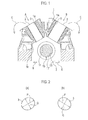
- a cylinder block 1 according to the present embodiment shown in Fig. 1 is applied to a V-type engine for an automobile.
- the cylinder block 1 is made of aluminum alloy, and thermally sprayed coatings 5 are formed on inner surfaces of its cylinder bores 3.
- Fig. 1 shows a condition where bearing caps 7 and a crankshaft 15 are assembled on the cylinder block 1 in which the thermally sprayed coatings 5 are formed on the inner surfaces of the cylinder bores 3 in an after-explained thermal spraying process.
- thermally sprayed coatings 5 By forming the thermally sprayed coatings 5 on the inner surfaces of the cylinder bores 3, properties such as an anti-abrasion property are improved.
- a method for forming the thermally sprayed coating 5 is known, and done by inserting a not-shown thermal spray gun into the cylinder bore 3 while rotating it, reciprocating it along an axial direction, and injecting melted droplets of coating material from a nozzle at an end of the thermal spray gun to attach them onto the inner surface of the cylinder bore 3.
- a wire made of ferrous material to be the coating material is continuously supplied to the nozzle from an outside of the thermal spray gun, and then the melted droplets are generated by melting the wire by a heat source such as plasma arc (Plasma Spray Coating).
- the bearing caps 7 are fastened, by bolts 9, on a bottom surface of the cylinder block 1 shown in Fig. 1 .
- Journals 17 of the crankshaft 15 are rotatably held between bearings 13 of the bearing caps 7 and bearings 11 of the cylinder block 1.
- An oil pan (not shown) is attached to an opposite bottom surface of the bearing caps to the cylinder block 1, and a cylinder head (not shown) is attached to an opposite upper surface of the cylinder block 1 to the bearing caps 7 .
- Fig. 3 shows manufacturing processes of the cylinder block 1 according to the present embodiment.
- the cylinder block 1 is cast in a cast process 19, and then the thermally sprayed coatings 5 are formed on the inner surfaces of the cylinder bores 3 in a thermal spraying process 21.
- machining such as cutting
- a leak test 25 is carried out.
- the leak test 25 is a test for fluid leaks, such as coolant leaks from a water jacket 1a, lubrication oil leaks in the crankcase 1b and so on.
- a leak test is conventionally well-known. For example, it is carried out by adding pressure to an inside of the water jacket 1a and an inside of the crankcase 1b in a state where they are sealed up, and then judging whether or not their inner pressures are maintained not lower than a prescribed value after predetermined time has elapsed.
- a finishing work process 29 for processing finishing works such as honing of the cylinder bores 3 is carried out.
- the honing is a process for abrading the inner surfaces of the cylinder bores 3 precisely, so that the above-explained thermally sprayed coatings 5 are abraded.
- high-accuracy cylindricity of the cylinder bores 3 is brought surely.
- dummy cylinder heads are also attached to the cylinder block 1.
- a diameter P of the cylinder bore(s) 3 along a lateral direction in Fig. 1 becomes longer than a diameter Q along a direction perpendicular to the lateral direction, so that a cross-sectional shape of the cylinder bore(s) 3 is deformed to have an ellipsoidal shape or an elongate circular shape.
- Such a deformation is generated by lateral inclinations of portions near the cylinder bores 3, that are caused by fastening of the bolts 9 positioned on both lateral sides with respect to a center between both banks of the cylinder bores 3, with respect to the center as a boundary as indicated by arrows C in Fig. 1 .
- an abraded amount in regions along the short diameter becomes larger than an abraded amount in regions along the long diameter.
- the regions along the short diameter are abraded more, so that the cross-sectional shape of the cylinder bore(s) 3 is made precisely circular.
- operations shown in Fig. 4 are carried out in the thermal spraying process 21 prior to the bearing cap assembling process 27 and the finishing work (honing) process 29.
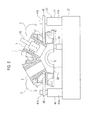
- a clamp device (clamping means) 31 shown in Fig. 5 deformations of the cylinder bores 3 to be caused by assembling the bearing caps 7 on the cylinder block 1 are intentionally generated (operation 21 a).
- support protrusions 39 for supporting the cylinder block 1 and oil-pressure cylinders (clamping mechanisms) 41 are provided on a bed 37 of the clamp device 31, support protrusions 39 for supporting the cylinder block 1 and oil-pressure cylinders (clamping mechanisms) 41 are provided.
- the support protrusions 39 support bottom surfaces (bearing cap mounting surfaces 43) of the cylinder block 1 near the bearings 11. Namely, the support protrusions 39 support portions near the bearings 11 from beneath (from a bottom side of the cylinder block 1).
- Each of the oil-pressure cylinders 41 is provided with a rod 41b that extends vertically from its main body 41a and can be stroked vertically, and a clamp arm 45 extending horizontally is attached to the rod 41b.
- an inner diameter(s) of a cylinder bore 3 of the cylinder block 1 in which the stress is not generated and an inner diameter(s) of the cylinder bore 3 in the cylinder block 1 on which the bearing caps 7 are assembled are preliminarily measured. Based on these measured results, the deformation of the cylinder bore 3 is monitored in the operation 21a shown in Fig. 5 , and the condition where the bearing caps 7 are assembled on the cylinder block 1 is duplicated. Note that it is substantially impossible to "perfectly duplicate" the condition where the bearing caps 7 are assembled on the cylinder block 1 by the clamp device 31, so that the "duplicate” used here means to vicariously duplicate the condition where the bearing caps 7 are assembled on the cylinder block 1.
- Fig. 5 shows a state where only one of the cylinder bores 3 is being measured, it is preferable to duplicate the condition where the bearing caps 7 are assembled on the cylinder block 1 while measuring all of the cylinder bores 3. However, it is acceptable to only one of the cylinder bores 3 is measured or to some of the cylinder bores 3 are measured (for example, a center cylinder bore 3 in each bank of a V6 engine, i.e. two cylinder bores 3 are measured).
- a deformation of a particular single cylinder bore 3 correlates with deformations of other cylinder bores 3 and a measured value of the single cylinder bore 3 is consistent with deformations of all cylinder bores 3, it is acceptable that a measurement by the measurement instrument 30 is made only in the particular single cylinder bore 3.
- the measurement instrument 30 it is preferable to carry out a measurement by the measurement instrument 30 for every cylinder block 1. However, if measurements were made for one or more cylinder blocks 1 and consistency between the condition where the bearing caps 7 are assembled on the cylinder block 1 and an applied load by the clamp arms 45 (the oil-pressure cylinders 41) is brought, it is acceptable to carry out a measurement by the measurement instrument 30 for not every cylinder block 1.
- the measurement instrument 30 may be a contact-type measurement instrument, or a non-contact-type measurement instrument. Further, it is preferable to measure an inner diameter of the cylinder bore 3 at plural positions along its axis (three positions are measured in Fig. 5 ), and it is especially preferable to carry out a measurement focusing on one side including a cylinder head(s) that presents a larger deformation.
- a machining work (boring) is made in the condition where the deformation of the cylinder bore(s) 3 is intentionally generated so that the cross-sectional shape (an ellipsoidal shape or an elongate circular shape due to the deformation) of the cylinder bore 3 becomes a precisely circular shape (an exactly circular shape) (operation 21b).
- cylindricity of the cylinder bore(s) 3 is corrected.
- the above machining work is carried out by inserting a boring bar 33 into the cylinder bore 3 while rotating it to cut the inner surface of the cylinder bore 3 by a cutting blade 35 provided at an end of the boring bar 33.
- the thermally sprayed coating(s) 5 is formed on the inner surface of the cylinder bore 3 by using known thermal spraying technique (operation 21c). Namely, coating material is attached onto the inner surface of the cylinder bore 3 by inserting a thermal spray gun 36 into the cylinder bore 3 while rotating it, reciprocating it along an axial direction, and injecting melted droplets of the coating material from a nozzle 38 at an end of the thermal spray gun 36.
- Shapes of the cylinder bore 3 during processes of the operations 21a to 21 c are shown in Fig. 8(a) to (c) .
- Fig. 8(a) the deformation of the cylinder bore 3 in the condition where the bearing caps 7 are assembled on the cylinder block 1 is duplicated by the operation 21a.
- Fig. 8(b) the inner surface of the cylinder bore 3 is cut by the operation 21b (boring), and thereby good cylindricity of the cylinder bore 3 in the above-explained duplicated condition is ensured.
- the thermally sprayed coating 5 is formed on the inner surface of the cylinder bore 3 in the above-explained duplicated condition by the operation 21c (formation of the thermally sprayed coating 5).
- the cylinder bore 3 is deformed to have an ellipsoidal shape or an elongate circular shape expanded in a lateral direction as shown in Fig. 8(a) by the operation 21a, the cylinder bore 3 whose deformation by the clamp device 31 is cancelled will have an ellipsoidal shape or an elongate circular shape expanded in a vertical direction perpendicular to the lateral direction as shown in Fig. 8(d) (because boring was carried out in the operation 21b).
- the bearing caps 7 are assembled on the cylinder block 1 (a shape of the cylinder bore(s) 3 has the shape shown in Fig. 8(d) ) in the bearing cap assembling process 27.
- stress due to fastening of the bolts 9 is generated in the cylinder block 1.
- the cylinder bores 3 are deformed again, and thereby returned into the condition shown in Fig. 8(c) .
- finishing works are made in the finishing work process 29 for the thermally sprayed coatings 5 of the cylinder bores 3 each having the circular shape shown in Fig. 8(c) .
- the inner surface of the thermally sprayed coating 5 already has the circular (cylindrical) shape as shown in Fig. 8(c) . Therefore, workings for correcting the cylindricity are not required when carrying out honing, and thereby working efficiency is improved (workability degradation is restricted).
- the inner surface of the cylinder bore(s) 3 (the thermally sprayed coating(s) 5) is improved further in its cylindricity by honing, and thereby has a precise circular shape.
- the thermally sprayed coating(s) 5 it is not required to correct the cylindricity of the cylinder bore(s) 3 (the thermally sprayed coating(s) 5) that is deformed as shown in Fig. 2 and thereby has an ellipsoidal shape or an elongate circular shape caused by assembling the bearing caps after forming the thermally sprayed coating 5.
- the thermally sprayed coating(s) 5 since it is not required to form the thermally sprayed coating(s) 5 thick in consideration of an abraded amount, it is not needed to use much coating material. Therefore, material costs can be restricted by elimination of a used amount of the coating material. In addition, since the used amount of the coating material is eliminated, working time for forming the thermally sprayed coating(s) 5 can be shortened.
- the thermal spraying process 21 is carried out following the cast process 19.
- the thermal spraying process 21 is carried out at a downstream of the manufacturing processes, e.g. directly before the finishing work process 29, the cylinder block 1 will be condemned if a casting failure is found at thermal spraying (especially, at boring for correcting cylindricity).
- process costs and working times required for processes from the cast process to the thermal spraying process are subject to be wasted.
- thermal spraying process 21 by carrying out the thermal spraying process 21 directly after the cast process 19, modifications for a manufacturing line can be reduced, and facility costs can be decreased. If the thermal spraying process 21 is carried out at a downstream of the manufacturing processes, e.g. followed by the finishing work process 29, it is needed to implement the thermal spraying process 21 into the middle of an existing manufacturing line, so that extent of modifications for the line is subject to become large. In consideration of these matters, it is preferable that the thermal spraying process is carried out next after the cast process 19 as in the present embodiment.
- a cylinder block 1A according to the present embodiment has a dimension that makes the deformations caused by assembling the bearing caps 7 smaller than those in the cylinder block 1 of the first embodiment (or, the cylinder block 1A is not deformed). Note that manufacturing processes and operations for manufacturing the cylinder block 1A of the present embodiment are the same as the manufacturing processes (see Fig. 3 ) and the operations (see Fig. 4 ) in the above-explained first embodiment.
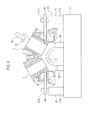
- cutout portions (stress absorbing portions) 49 for absorbing stress are formed near the bearing cap mounting surfaces 43 on outer sides of the banks as shown in Fig. 9 .
- the cutout portions 49 are formed just above clamped portions by the clamp arms 45 of the clamp device 31 (on sides of heads of the cylinder block 1).
- rigidity near the cutout portions 49 is restricted to be low. In this manners, by restricting rigidity of some portions of the cylinder block 1A, stress generated when assembling the bearing caps 7 on the cylinder block 1A can be absorbed and thereby deformations of the cylinder bores 3 can be restricted.
- cutout portions stress absorbing portions 49
- following methods can be adopted. (1) If reinforcing portions (such as ribs) are formed primordially at the positions of the cutout portions 49, the ribs are removed (i.e. the cutout portions 49 are formed by removing the reinforcing portions from the cylinder block). (2) Portions corresponding to the cutout portions 49 are made thinner (i.e. the cutout portions 49 are formed by making their thickness smaller).
- the thermally sprayed coating is formed on the inner surface of the cylinder bore that has been worked to have a precise circular shape in the deformed condition equivalent to that when the bearing caps are assembled.
- the inner surface of the cylinder bore in the condition where the bearing caps have been assembled has promised cylindricity. Therefore, it is not required, in the finishing work (honing) of the coating surface, to correct the cylindricity, so that working efficiency can be improved (workability degradation can be restricted).
- each of the above embodiments is explained by taking the cylinder block 1 (1A) of a V-type engine for an automobile as an example. Since deformation of the cylinder block 1 caused by assembling the bearing caps is apparent in a V-type engine in which the cylinder bores 3 are formed on its both banks (excluding horizontally-opposed engine), the present invention is effective especially for a cylinder block of a V-type engine. However, the present invention can be applied to a cylinder block of other types of engines such as an inline engine, and thereby the above-explained effects can be brought similarly.
Landscapes
- Chemical & Material Sciences (AREA)
- Engineering & Computer Science (AREA)
- Mechanical Engineering (AREA)
- Plasma & Fusion (AREA)
- Physics & Mathematics (AREA)
- Chemical Kinetics & Catalysis (AREA)
- Materials Engineering (AREA)
- Metallurgy (AREA)
- Organic Chemistry (AREA)
- General Engineering & Computer Science (AREA)
- Combustion & Propulsion (AREA)
- Cylinder Crankcases Of Internal Combustion Engines (AREA)
- Coating By Spraying Or Casting (AREA)
Abstract
Description
- The present invention relates to a cylinder block to form a spray coating on an inner surface of a cylinder bore, and to a manufacturing method therefor.
- In view of power improvement, fuel consumption improvement, emission performance improvement, down-sizing or light-weighting of an internal combustion engine, elimination of a cylinder liner to be applied to a cylinder bore(s) of an aluminum cylinder block is desired. As one of techniques instead of a cylinder liner, it is known that a thermally sprayed coating is formed on an inner surface of a cylinder bore by use of ferrous material (for example, see Patent Literature 1 listed below).
- Patent Literature 1: Japanese Unexamined Patent Publication No.
2006-291336 - In a case where bearing caps are assembled, by bolts, on a cylinder block on which a thermally sprayed coating is formed on an inner surface of a cylinder bore(s), the cylinder bore is deformed due to stress generated by fastening them. According to this deformation of the cylinder bore, cylindricity of the cylinder bore is degraded.
- With respect to the cylinder bore on which the thermally sprayed coating is formed and of which cylindricity is degraded, its inner surface is deformed to have not a precise circular cylindrical shape but an ellipsoidal cylindrical shape or an elongate circular cylindrical shape. Therefore, when carrying out finishing works (honing) with the cylinder bore on which the thermally sprayed coating is formed and of which cylindricity is degraded, it is required to modify the cylinder bore to have a precise circular cylindrical shape and thereby workability becomes degraded.
- Therefore, an object of the present invention is to restrict workability degradation of finishing works, carried out after assembling bearing caps, of an inner surface of a cylinder bore on which a thermally sprayed coating is formed.
- A first aspect of the present invention provides a method for manufacturing a cylinder block provided with a plurality of cylinder bores, the method comprising: holding the cylinder block by a clamp device; generating stress in the cylinder block by a holding force of the clamp device to duplicate deformations of the plurality of cylinder bores after assembling bearing caps thereon; carrying out boring with the plurality of cylinder bores that are deformed in a condition where the stress is generated, respectively; and forming a thermally sprayed coating on each inner surfaces of the plurality of cylinder bores, after the boring, that are deformed in the condition where the stress is generated.
- A second aspect of the present invention provides a cylinder block provided with a plurality of cylinder bores, wherein, in a condition where deformations of the plurality of cylinder bores on which bearing caps are assembled are duplicated by generating stress in the cylinder block by use of a clamp device, boring is carried out with the plurality of cylinder bores, respectively, and then a thermally sprayed coating is formed on each inner surface of the plurality of cylinder bores after carrying out the boring.
-
- [
Fig. 1 ] It is a cross-sectional view showing a condition where bearing caps are assembled on a cylinder block according to a first embodiment. - [
Fig. 2 ] (a) is a schematic diagram showing a deformation of a cylinder bore viewed along an arrow A inFig. 1 , and (b) is a schematic diagram showing a deformation of a cylinder bore viewed along an arrow B inFig. 1 . - [
Fig. 3 ] It is a manufacturing process diagram of the cylinder block according to the first embodiment. - [
Fig. 4 ] It is a flowchart showing operations in a thermal spraying process in the flowchart shown inFig. 3 . - [
Fig. 5 ] It is a cross-sectional view showing a condition where deformations by assembling bearing caps are generated in the cylinder bores by a clamp device. - [
Fig. 6 ] It is a cross-sectional view showing a boring process of the cylinder bore. - [
Fig. 7 ] It is a cross-sectional view showing a thermal spraying process of the cylinder bore. - [
Fig. 8 ] It is a schematic diagram showing deformations of a cylinder bore associated with the operations inFig. 4 . - [
Fig. 9 ] It is a cross-sectional view of a cylinder block according to a second embodiment. - Hereinafter, embodiments will be explained with reference to the drawings.
- A cylinder block 1 according to the present embodiment shown in
Fig. 1 is applied to a V-type engine for an automobile. The cylinder block 1 is made of aluminum alloy, and thermally sprayedcoatings 5 are formed on inner surfaces of itscylinder bores 3.Fig. 1 shows a condition where bearingcaps 7 and acrankshaft 15 are assembled on the cylinder block 1 in which the thermally sprayedcoatings 5 are formed on the inner surfaces of thecylinder bores 3 in an after-explained thermal spraying process. - By forming the thermally sprayed
coatings 5 on the inner surfaces of thecylinder bores 3, properties such as an anti-abrasion property are improved. A method for forming the thermally sprayedcoating 5 is known, and done by inserting a not-shown thermal spray gun into thecylinder bore 3 while rotating it, reciprocating it along an axial direction, and injecting melted droplets of coating material from a nozzle at an end of the thermal spray gun to attach them onto the inner surface of thecylinder bore 3. A wire made of ferrous material to be the coating material is continuously supplied to the nozzle from an outside of the thermal spray gun, and then the melted droplets are generated by melting the wire by a heat source such as plasma arc (Plasma Spray Coating). - The
bearing caps 7 are fastened, bybolts 9, on a bottom surface of the cylinder block 1 shown inFig. 1 .Journals 17 of thecrankshaft 15 are rotatably held betweenbearings 13 of thebearing caps 7 andbearings 11 of the cylinder block 1. - An oil pan (not shown) is attached to an opposite bottom surface of the bearing caps to the cylinder block 1, and a cylinder head (not shown) is attached to an opposite upper surface of the cylinder block 1 to the
bearing caps 7 . -
Fig. 3 shows manufacturing processes of the cylinder block 1 according to the present embodiment. The cylinder block 1 is cast in acast process 19, and then the thermally sprayedcoatings 5 are formed on the inner surfaces of thecylinder bores 3 in athermal spraying process 21. Subsequently, machining (such as cutting) for outer sides of the cylinder block 1 is carried out in apre-stage machining process 23, and then aleak test 25 is carried out. - The
leak test 25 is a test for fluid leaks, such as coolant leaks from awater jacket 1a, lubrication oil leaks in thecrankcase 1b and so on. A leak test is conventionally well-known. For example, it is carried out by adding pressure to an inside of thewater jacket 1a and an inside of thecrankcase 1b in a state where they are sealed up, and then judging whether or not their inner pressures are maintained not lower than a prescribed value after predetermined time has elapsed. - Then, through a bearing
cap assembling process 27 for assembling thebearing caps 7, afinishing work process 29 for processing finishing works such as honing of thecylinder bores 3 is carried out. The honing is a process for abrading the inner surfaces of thecylinder bores 3 precisely, so that the above-explained thermally sprayedcoatings 5 are abraded. By the honing, high-accuracy cylindricity of thecylinder bores 3 is brought surely. In the honing, dummy cylinder heads are also attached to the cylinder block 1. - When the
bearing caps 7 is fastened, by thebolts 9, on the cylinder block 1 in the bearingcap assembling process 27 prior to the above-explained finishing work (honing)process 29, stress is generated in the cylinder block 1. The cylinder block 1, i.e. the cylinder bore(s) 3 is deformed due to the stress, so that the cylindricity becomes degraded. Specifically, as shown inFig. 2(a) that is a schematic diagram viewed along an arrow A inFig. 1 and inFig. 2(b) that is a schematic diagram viewed along an arrow B inFig. 1 , a diameter P of the cylinder bore(s) 3 along a lateral direction inFig. 1 becomes longer than a diameter Q along a direction perpendicular to the lateral direction, so that a cross-sectional shape of the cylinder bore(s) 3 is deformed to have an ellipsoidal shape or an elongate circular shape. - Such a deformation is generated by lateral inclinations of portions near the
cylinder bores 3, that are caused by fastening of thebolts 9 positioned on both lateral sides with respect to a center between both banks of thecylinder bores 3, with respect to the center as a boundary as indicated by arrows C inFig. 1 . - If the cylinder bore(s) 3 having an ellipsoidal shape or an elongate circular shape due to the above-explained deformation is processed by the honing, an abraded amount in regions along the short diameter becomes larger than an abraded amount in regions along the long diameter. The regions along the short diameter are abraded more, so that the cross-sectional shape of the cylinder bore(s) 3 is made precisely circular. However, in this case, it is required to from the thermally sprayed
coating 5 thick preliminarily in consideration of the abraded amount of the regions along the short diameter, so that much coating material is needed. - Therefore, in the present embodiment, operations shown in
Fig. 4 are carried out in thethermal spraying process 21 prior to the bearingcap assembling process 27 and the finishing work (honing)process 29. Namely, by used of a clamp device (clamping means) 31 shown inFig. 5 , deformations of thecylinder bores 3 to be caused by assembling thebearing caps 7 on the cylinder block 1 are intentionally generated (operation 21 a). - On a
bed 37 of theclamp device 31, supportprotrusions 39 for supporting the cylinder block 1 and oil-pressure cylinders (clamping mechanisms) 41 are provided. Thesupport protrusions 39 support bottom surfaces (bearing cap mounting surfaces 43) of the cylinder block 1 near thebearings 11. Namely, thesupport protrusions 39 support portions near thebearings 11 from beneath (from a bottom side of the cylinder block 1). Each of the oil-pressure cylinders 41 is provided with arod 41b that extends vertically from itsmain body 41a and can be stroked vertically, and aclamp arm 45 extending horizontally is attached to therod 41b. - In a state where ends of the
clamp arms 45 are located aboveupper surfaces 47 of side portions of the cylinder block 1, respectively, therods 41b are moved downward by driving the oil-pressure cylinders 41. Namely, theclamp arms 45 clamp lower side-edges of the cylinder block 1 from above (from a head side of the cylinder block 1). Therefore, the cylinder block 1 is held firmly by theclamp arms 45 so as to endure works (works in theoperations 21a to 21c), and stress is generated in the cylinder block 1 due to load application by theclamp arms 45. This will cause the deformations indicated by the arrows C that are to be generated when assembling thebearing caps 7 on the cylinder block 1. At this time, as shown inFig. 5 , a condition where thebearing caps 7 are assembled on the cylinder block 1 is duplicated by inserting ameasurement instrument 30 for measuring inner diameters of the cylinder bore 3 into thecylinder bore 3 and monitoring the deformations in the cylinder block 1. - Here, an inner diameter(s) of a
cylinder bore 3 of the cylinder block 1 in which the stress is not generated and an inner diameter(s) of the cylinder bore 3 in the cylinder block 1 on which the bearing caps 7 are assembled are preliminarily measured. Based on these measured results, the deformation of the cylinder bore 3 is monitored in theoperation 21a shown inFig. 5 , and the condition where the bearing caps 7 are assembled on the cylinder block 1 is duplicated. Note that it is substantially impossible to "perfectly duplicate" the condition where the bearing caps 7 are assembled on the cylinder block 1 by theclamp device 31, so that the "duplicate" used here means to vicariously duplicate the condition where the bearing caps 7 are assembled on the cylinder block 1. - In addition, although
Fig. 5 shows a state where only one of the cylinder bores 3 is being measured, it is preferable to duplicate the condition where the bearing caps 7 are assembled on the cylinder block 1 while measuring all of the cylinder bores 3. However, it is acceptable to only one of the cylinder bores 3 is measured or to some of the cylinder bores 3 are measured (for example, a center cylinder bore 3 in each bank of a V6 engine, i.e. two cylinder bores 3 are measured). In addition, if a deformation of a particularsingle cylinder bore 3 correlates with deformations of other cylinder bores 3 and a measured value of thesingle cylinder bore 3 is consistent with deformations of all cylinder bores 3, it is acceptable that a measurement by themeasurement instrument 30 is made only in the particularsingle cylinder bore 3. - Further, it is preferable to carry out a measurement by the
measurement instrument 30 for every cylinder block 1. However, if measurements were made for one or more cylinder blocks 1 and consistency between the condition where the bearing caps 7 are assembled on the cylinder block 1 and an applied load by the clamp arms 45 (the oil-pressure cylinders 41) is brought, it is acceptable to carry out a measurement by themeasurement instrument 30 for not every cylinder block 1. - Note that the
measurement instrument 30 may be a contact-type measurement instrument, or a non-contact-type measurement instrument. Further, it is preferable to measure an inner diameter of the cylinder bore 3 at plural positions along its axis (three positions are measured inFig. 5 ), and it is especially preferable to carry out a measurement focusing on one side including a cylinder head(s) that presents a larger deformation. - Subsequently, as shown in
Fig. 6 , a machining work (boring) is made in the condition where the deformation of the cylinder bore(s) 3 is intentionally generated so that the cross-sectional shape (an ellipsoidal shape or an elongate circular shape due to the deformation) of the cylinder bore 3 becomes a precisely circular shape (an exactly circular shape) (operation 21b). By the above machining work, cylindricity of the cylinder bore(s) 3 is corrected. As shown inFig. 6 , the above machining work is carried out by inserting aboring bar 33 into the cylinder bore 3 while rotating it to cut the inner surface of the cylinder bore 3 by acutting blade 35 provided at an end of theboring bar 33. - Subsequently, as shown in
Fig. 7 , the thermally sprayed coating(s) 5 is formed on the inner surface of the cylinder bore 3 by using known thermal spraying technique (operation 21c). Namely, coating material is attached onto the inner surface of the cylinder bore 3 by inserting athermal spray gun 36 into the cylinder bore 3 while rotating it, reciprocating it along an axial direction, and injecting melted droplets of the coating material from anozzle 38 at an end of thethermal spray gun 36. - Shapes of the cylinder bore 3 during processes of the
operations 21a to 21 c are shown inFig. 8(a) to (c) . Namely, as shown inFig. 8(a) , the deformation of the cylinder bore 3 in the condition where the bearing caps 7 are assembled on the cylinder block 1 is duplicated by theoperation 21a. Subsequently, as shown inFig. 8(b) , the inner surface of the cylinder bore 3 is cut by theoperation 21b (boring), and thereby good cylindricity of the cylinder bore 3 in the above-explained duplicated condition is ensured. Further, as shown inFig. 8(c) , the thermally sprayedcoating 5 is formed on the inner surface of the cylinder bore 3 in the above-explained duplicated condition by theoperation 21c (formation of the thermally sprayed coating 5). - After the above-explained
thermal spraying process 21, holding (stress loading) of the cylinder block 1 by theclamp device 31 is released, and then thepre-stage machining process 23 and theleak test 25 are carried out sequentially (seeFig. 3 ). Since holding of the cylinder block 1 by theclamp device 31 is released in thepre-stage machining process 23 and theleak test 25, the duplicated deformations of the cylinder bores 3 are also cancelled. Therefore, the cylinder bore(s) 3 is deformed in a direction inverse to a direction of the deformation by theclamp device 31. Note that the directions inverse to each other are directions that are perpendicular to each other in a plane orthogonal to an axis of thecylinder bore 3. - Namely, if the cylinder bore 3 is deformed to have an ellipsoidal shape or an elongate circular shape expanded in a lateral direction as shown in
Fig. 8(a) by theoperation 21a, the cylinder bore 3 whose deformation by theclamp device 31 is cancelled will have an ellipsoidal shape or an elongate circular shape expanded in a vertical direction perpendicular to the lateral direction as shown inFig. 8(d) (because boring was carried out in theoperation 21b). - After the
leak test 25, the bearing caps 7 are assembled on the cylinder block 1 (a shape of the cylinder bore(s) 3 has the shape shown inFig. 8(d) ) in the bearingcap assembling process 27. After the bearing caps 7 are assembled on the cylinder block 1, stress due to fastening of thebolts 9 is generated in the cylinder block 1. As a result, the cylinder bores 3 are deformed again, and thereby returned into the condition shown inFig. 8(c) . - Then, finishing works (honing) are made in the finishing
work process 29 for the thermally sprayedcoatings 5 of the cylinder bores 3 each having the circular shape shown inFig. 8(c) . When carrying out honing with the thermally sprayed coating(s) 5, the inner surface of the thermally sprayedcoating 5 already has the circular (cylindrical) shape as shown inFig. 8(c) . Therefore, workings for correcting the cylindricity are not required when carrying out honing, and thereby working efficiency is improved (workability degradation is restricted). The inner surface of the cylinder bore(s) 3 (the thermally sprayed coating(s) 5) is improved further in its cylindricity by honing, and thereby has a precise circular shape. - According to the present embodiment, it is not required to correct the cylindricity of the cylinder bore(s) 3 (the thermally sprayed coating(s) 5) that is deformed as shown in
Fig. 2 and thereby has an ellipsoidal shape or an elongate circular shape caused by assembling the bearing caps after forming the thermally sprayedcoating 5. Namely, since it is not required to form the thermally sprayed coating(s) 5 thick in consideration of an abraded amount, it is not needed to use much coating material. Therefore, material costs can be restricted by elimination of a used amount of the coating material. In addition, since the used amount of the coating material is eliminated, working time for forming the thermally sprayed coating(s) 5 can be shortened. - Note that the
thermal spraying process 21 is carried out following thecast process 19. In a case where thethermal spraying process 21 is carried out at a downstream of the manufacturing processes, e.g. directly before the finishingwork process 29, the cylinder block 1 will be condemned if a casting failure is found at thermal spraying (especially, at boring for correcting cylindricity). In this case, process costs and working times required for processes from the cast process to the thermal spraying process (including the pre-stage machining process) are subject to be wasted. - In addition, by carrying out the
thermal spraying process 21 directly after thecast process 19, modifications for a manufacturing line can be reduced, and facility costs can be decreased. If thethermal spraying process 21 is carried out at a downstream of the manufacturing processes, e.g. followed by the finishingwork process 29, it is needed to implement thethermal spraying process 21 into the middle of an existing manufacturing line, so that extent of modifications for the line is subject to become large. In consideration of these matters, it is preferable that the thermal spraying process is carried out next after thecast process 19 as in the present embodiment. - A
cylinder block 1A according to the present embodiment has a dimension that makes the deformations caused by assembling the bearing caps 7 smaller than those in the cylinder block 1 of the first embodiment (or, thecylinder block 1A is not deformed). Note that manufacturing processes and operations for manufacturing thecylinder block 1A of the present embodiment are the same as the manufacturing processes (seeFig. 3 ) and the operations (seeFig. 4 ) in the above-explained first embodiment. - Specifically, in the
cylinder block 1A, cutout portions (stress absorbing portions) 49 for absorbing stress (i.e. for preventing stress from acting on the cylinder bores 3) are formed near the bearingcap mounting surfaces 43 on outer sides of the banks as shown inFig. 9 . Thecutout portions 49 are formed just above clamped portions by theclamp arms 45 of the clamp device 31 (on sides of heads of the cylinder block 1). By forming thecutout portions 49, rigidity near thecutout portions 49 is restricted to be low. In this manners, by restricting rigidity of some portions of thecylinder block 1A, stress generated when assembling the bearing caps 7 on thecylinder block 1A can be absorbed and thereby deformations of the cylinder bores 3 can be restricted. - Namely, even when the bearing caps 7 are fastened, by the
bolts 9, on thecylinder block 1A in the present embodiment, deformations of the cylinder bores 3 are restricted and thereby their precisely (exactly) circular shapes can be kept. Therefore, according to the present embodiment, it is not required to correct the cylindricity of the cylinder bore(s) 3 when boring the inner surface of the cylinder bore 3 (the thermally sprayed coating 5) in the condition where the bearing caps 7 are assembled on thecylinder block 1A, similarly to the above-explained first embodiment. As a result, working efficiency is improved (workability degradation is restricted). - In addition, since it is not required to correct the cylindricity of the cylinder bore(s) 3 when boring the inner surface of the cylinder bore 3 (the thermally sprayed coating 5), it is not needed to use much coating material. Therefore, material costs can be restricted by elimination of a used amount of the coating material.
- Instead of forming the above-explained cutout portions (stress absorbing portions) 49, following methods can be adopted. (1) If reinforcing portions (such as ribs) are formed primordially at the positions of the
cutout portions 49, the ribs are removed (i.e. thecutout portions 49 are formed by removing the reinforcing portions from the cylinder block). (2) Portions corresponding to thecutout portions 49 are made thinner (i.e. thecutout portions 49 are formed by making their thickness smaller). - According to the above embodiments, the thermally sprayed coating is formed on the inner surface of the cylinder bore that has been worked to have a precise circular shape in the deformed condition equivalent to that when the bearing caps are assembled. Thus, the inner surface of the cylinder bore in the condition where the bearing caps have been assembled has promised cylindricity. Therefore, it is not required, in the finishing work (honing) of the coating surface, to correct the cylindricity, so that working efficiency can be improved (workability degradation can be restricted).
- The entire contents of Japanese Patent Applications
2011-281317 (filed December 22, 2011 - Note that each of the above embodiments is explained by taking the cylinder block 1 (1A) of a V-type engine for an automobile as an example. Since deformation of the cylinder block 1 caused by assembling the bearing caps is apparent in a V-type engine in which the cylinder bores 3 are formed on its both banks (excluding horizontally-opposed engine), the present invention is effective especially for a cylinder block of a V-type engine. However, the present invention can be applied to a cylinder block of other types of engines such as an inline engine, and thereby the above-explained effects can be brought similarly.
Claims (8)
- A method for manufacturing a cylinder block provided with a plurality of cylinder bores, the method comprising:holding the cylinder block by a clamp device;generating stress in the cylinder block by a holding force of the clamp device to duplicate deformations of the plurality of cylinder bores after assembling bearing caps thereon;carrying out boring with the plurality of cylinder bores that are deformed in a condition where the stress is generated, respectively; andforming a thermally sprayed coating on each inner surfaces of the plurality of cylinder bores, after the boring, that are deformed in the condition where the stress is generated.
- The method for manufacturing a cylinder block according to claim 1, wherein,
when generating the stress in the cylinder block by a holding force of the clamp device, an inner diameter of at least one of the plurality of cylinder bores is measured, and
the deformations of the plurality of cylinder bores are controlled by adjusting the holding force of the clamp device based on the measured inner diameter. - The method for manufacturing a cylinder block according to claim 1 or 2, wherein
the cylinder block is dismounted from the clamp device after the thermally sprayed coating is formed on an inner surface of the cylinder bore,
a crankshaft and the bearing caps are assembled on the cylinder block after carrying out another work process or a test process, and
honing is carried out with the thermally sprayed coating formed on an inner surface of the cylinder bore of the cylinder block on which the crankshaft and the bearing caps are assembled. - The method for manufacturing a cylinder block according to any one of claims 1 to 3, wherein
the clamp device includes a plurality of support protrusions for supporting, from beneath, portions near bearings of the cylinder block on which the bearing caps are to be assembled, and a plurality of clamping mechanisms provided with clamp arms for clamping lower side-edges of the cylinder block from above. - The method for manufacturing a cylinder block according to any one of claims 1 to 4, wherein
the cylinder block is a cylinder block of a V-type engine. - A cylinder block provided with a plurality of cylinder bores, wherein,
in a condition where deformations of the plurality of cylinder bores on which bearing caps are assembled are duplicated by generating stress in the cylinder block by use of a clamp device, boring is carried out with the plurality of cylinder bores, respectively, and then a thermally sprayed coating is formed on each inner surface of the plurality of cylinder bores after carrying out the boring. - The cylinder block according to claim 6, wherein
a stress absorbing portion for restricting the deformations of the plurality of cylinder bores on which the bearing caps are assembled is formed on the cylinder block. - The cylinder block according to claim 7, wherein
the stress absorbing portion is a cutout portion formed just above a clamped portion of the cylinder block by the clamp device.
Applications Claiming Priority (2)
| Application Number | Priority Date | Filing Date | Title |
|---|---|---|---|
| JP2011281317 | 2011-12-22 | ||
| PCT/JP2012/078597 WO2013094323A1 (en) | 2011-12-22 | 2012-11-05 | Method for manufacturing cylinder block, and cylinder block |
Publications (3)
| Publication Number | Publication Date |
|---|---|
| EP2796698A1 true EP2796698A1 (en) | 2014-10-29 |
| EP2796698A4 EP2796698A4 (en) | 2015-06-24 |
| EP2796698B1 EP2796698B1 (en) | 2017-05-03 |
Family
ID=48668223
Family Applications (1)
| Application Number | Title | Priority Date | Filing Date |
|---|---|---|---|
| EP12859226.8A Active EP2796698B1 (en) | 2011-12-22 | 2012-11-05 | Method for manufacturing cylinder block, and cylinder block |
Country Status (6)
| Country | Link |
|---|---|
| US (1) | US9797335B2 (en) |
| EP (1) | EP2796698B1 (en) |
| JP (1) | JP5725204B2 (en) |
| CN (1) | CN104011357B (en) |
| MX (1) | MX345392B (en) |
| WO (1) | WO2013094323A1 (en) |
Cited By (1)
| Publication number | Priority date | Publication date | Assignee | Title |
|---|---|---|---|---|
| CN104741874A (en) * | 2015-03-05 | 2015-07-01 | 长治清华机械厂 | Cylinder barrel inner hole overtravel grinding method |
Families Citing this family (3)
| Publication number | Priority date | Publication date | Assignee | Title |
|---|---|---|---|---|
| CN106826113A (en) * | 2017-01-17 | 2017-06-13 | 重庆长安汽车股份有限公司 | A kind of cylinder holes processing method of the aluminium alloy cylinder with simulation cylinder head |
| JP7280073B2 (en) * | 2019-03-19 | 2023-05-23 | ダイハツ工業株式会社 | Cylinder block for multi-cylinder internal combustion engine and manufacturing method thereof |
| JP7491275B2 (en) * | 2021-08-17 | 2024-05-28 | トヨタ自動車株式会社 | Ladder frame manufacturing method |
Family Cites Families (12)
| Publication number | Priority date | Publication date | Assignee | Title |
|---|---|---|---|---|
| JP4036200B2 (en) * | 2004-03-10 | 2008-01-23 | マツダ株式会社 | Cylinder block structure of multi-cylinder engine and manufacturing method thereof |
| JP4300180B2 (en) * | 2004-11-26 | 2009-07-22 | トーヨーエイテック株式会社 | Cylinder bore machining method and machine |
| JP4692052B2 (en) | 2005-04-14 | 2011-06-01 | 日産自動車株式会社 | Thermal spray masking method and masking apparatus for cylinder block |
| JP4591393B2 (en) * | 2005-11-14 | 2010-12-01 | トヨタ自動車株式会社 | Cylinder block manufacturing method and cylinder block |
| JP4577234B2 (en) * | 2006-02-24 | 2010-11-10 | トヨタ自動車株式会社 | Cylinder block manufacturing method and cylinder block |
| JP4710802B2 (en) * | 2006-03-07 | 2011-06-29 | 日産自動車株式会社 | Member with circular hole inner surface, processing method and processing device for circular hole inner surface |
| JP2007270620A (en) * | 2006-03-30 | 2007-10-18 | Toyota Motor Corp | Cylinder block and cylinder block manufacturing method |
| JP4552953B2 (en) * | 2007-03-08 | 2010-09-29 | トヨタ自動車株式会社 | Cylinder block machining method and apparatus used therefor |
| JP4905199B2 (en) | 2007-03-19 | 2012-03-28 | いすゞ自動車株式会社 | Measuring method and measuring device for cylinder bore |
| JP2009197309A (en) * | 2008-02-25 | 2009-09-03 | Nissan Motor Co Ltd | Method for forming thermally sprayed film |
| JP5504621B2 (en) * | 2008-02-29 | 2014-05-28 | 日産自動車株式会社 | Thermal spraying apparatus for cylinder bore and thermal spray film forming method |
| EP2283956B1 (en) * | 2008-04-11 | 2013-04-03 | Honda Motor Co., Ltd. | Device for boring a non-round hole |
-
2012
- 2012-11-05 CN CN201280063755.5A patent/CN104011357B/en active Active
- 2012-11-05 US US14/367,590 patent/US9797335B2/en active Active
- 2012-11-05 JP JP2013550176A patent/JP5725204B2/en active Active
- 2012-11-05 EP EP12859226.8A patent/EP2796698B1/en active Active
- 2012-11-05 MX MX2014006885A patent/MX345392B/en active IP Right Grant
- 2012-11-05 WO PCT/JP2012/078597 patent/WO2013094323A1/en not_active Ceased
Cited By (1)
| Publication number | Priority date | Publication date | Assignee | Title |
|---|---|---|---|---|
| CN104741874A (en) * | 2015-03-05 | 2015-07-01 | 长治清华机械厂 | Cylinder barrel inner hole overtravel grinding method |
Also Published As
| Publication number | Publication date |
|---|---|
| MX2014006885A (en) | 2014-09-08 |
| WO2013094323A1 (en) | 2013-06-27 |
| MX345392B (en) | 2017-01-30 |
| EP2796698A4 (en) | 2015-06-24 |
| JP5725204B2 (en) | 2015-05-27 |
| EP2796698B1 (en) | 2017-05-03 |
| CN104011357B (en) | 2017-03-08 |
| US9797335B2 (en) | 2017-10-24 |
| CN104011357A (en) | 2014-08-27 |
| JPWO2013094323A1 (en) | 2015-04-27 |
| US20140345135A1 (en) | 2014-11-27 |
Similar Documents
| Publication | Publication Date | Title |
|---|---|---|
| US9797335B2 (en) | Method for manufacturing cylinder block | |
| US8191529B2 (en) | Method of manufacturing an engine block | |
| EP3021998B1 (en) | Engine block assembly and method of manufacturing the engine block assembly | |
| EP2796697B1 (en) | Method for manufacturing a cylinder block of a v-engine | |
| US8689762B2 (en) | Cylinder head rocker arm stand repair and process | |
| CN103946606A (en) | Functionally optimized design of a cylinder liner | |
| US8833330B2 (en) | Method of manufacturing an engine block | |
| US9784208B2 (en) | Cylinder liner having roll-burnished recess | |
| US5167182A (en) | Modular fluid actuator | |
| US20190107144A1 (en) | Machining oval cores in crankshafts | |
| US6195886B1 (en) | Method of repairing a cylinder head having cooling water passages | |
| EP3015194A1 (en) | Method for manufacturing cylinder block | |
| WO2013077147A1 (en) | Manufacturing method for cylinder block, and cylinder block | |
| CN104487720A (en) | High Phosphorus Electroless Nickel (HPEN) treatment for bushless connecting rods | |
| JPS62287965A (en) | Machining method for engine cylinder | |
| JP2004036511A (en) | Cylinder block for internal combustion engine and processing method thereof | |
| JP4300180B2 (en) | Cylinder bore machining method and machine | |
| US20160356240A1 (en) | Remanufactured cylinder block for internal combustion engine | |
| CN211205108U (en) | Special tool for detecting and maintaining engine cylinder block crankshaft hole seat | |
| JP6015245B2 (en) | Cylinder block and honing method | |
| JPS61200357A (en) | Light alloy made piston for internal-combustion engine |
Legal Events
| Date | Code | Title | Description |
|---|---|---|---|
| PUAI | Public reference made under article 153(3) epc to a published international application that has entered the european phase |
Free format text: ORIGINAL CODE: 0009012 |
|
| 17P | Request for examination filed |
Effective date: 20140716 |
|
| AK | Designated contracting states |
Kind code of ref document: A1 Designated state(s): AL AT BE BG CH CY CZ DE DK EE ES FI FR GB GR HR HU IE IS IT LI LT LU LV MC MK MT NL NO PL PT RO RS SE SI SK SM TR |
|
| DAX | Request for extension of the european patent (deleted) | ||
| REG | Reference to a national code |
Ref country code: DE Ref legal event code: R079 Ref document number: 602012032100 Country of ref document: DE Free format text: PREVIOUS MAIN CLASS: F02F0001000000 Ipc: C23C0004020000 |
|
| RA4 | Supplementary search report drawn up and despatched (corrected) |
Effective date: 20150526 |
|
| RIC1 | Information provided on ipc code assigned before grant |
Ipc: C23C 4/02 20060101AFI20150519BHEP Ipc: C23C 4/18 20060101ALI20150519BHEP |
|
| 17Q | First examination report despatched |
Effective date: 20160310 |
|
| GRAP | Despatch of communication of intention to grant a patent |
Free format text: ORIGINAL CODE: EPIDOSNIGR1 |
|
| INTG | Intention to grant announced |
Effective date: 20170109 |
|
| GRAS | Grant fee paid |
Free format text: ORIGINAL CODE: EPIDOSNIGR3 |
|
| GRAA | (expected) grant |
Free format text: ORIGINAL CODE: 0009210 |
|
| AK | Designated contracting states |
Kind code of ref document: B1 Designated state(s): AL AT BE BG CH CY CZ DE DK EE ES FI FR GB GR HR HU IE IS IT LI LT LU LV MC MK MT NL NO PL PT RO RS SE SI SK SM TR |
|
| REG | Reference to a national code |
Ref country code: GB Ref legal event code: FG4D |
|
| REG | Reference to a national code |
Ref country code: AT Ref legal event code: REF Ref document number: 890072 Country of ref document: AT Kind code of ref document: T Effective date: 20170515 Ref country code: CH Ref legal event code: EP |
|
| REG | Reference to a national code |
Ref country code: IE Ref legal event code: FG4D |
|
| REG | Reference to a national code |
Ref country code: DE Ref legal event code: R096 Ref document number: 602012032100 Country of ref document: DE |
|
| REG | Reference to a national code |
Ref country code: NL Ref legal event code: MP Effective date: 20170503 |
|
| REG | Reference to a national code |
Ref country code: AT Ref legal event code: MK05 Ref document number: 890072 Country of ref document: AT Kind code of ref document: T Effective date: 20170503 |
|
| REG | Reference to a national code |
Ref country code: LT Ref legal event code: MG4D |
|
| PG25 | Lapsed in a contracting state [announced via postgrant information from national office to epo] |
Ref country code: AT Free format text: LAPSE BECAUSE OF FAILURE TO SUBMIT A TRANSLATION OF THE DESCRIPTION OR TO PAY THE FEE WITHIN THE PRESCRIBED TIME-LIMIT Effective date: 20170503 Ref country code: LT Free format text: LAPSE BECAUSE OF FAILURE TO SUBMIT A TRANSLATION OF THE DESCRIPTION OR TO PAY THE FEE WITHIN THE PRESCRIBED TIME-LIMIT Effective date: 20170503 Ref country code: FI Free format text: LAPSE BECAUSE OF FAILURE TO SUBMIT A TRANSLATION OF THE DESCRIPTION OR TO PAY THE FEE WITHIN THE PRESCRIBED TIME-LIMIT Effective date: 20170503 Ref country code: HR Free format text: LAPSE BECAUSE OF FAILURE TO SUBMIT A TRANSLATION OF THE DESCRIPTION OR TO PAY THE FEE WITHIN THE PRESCRIBED TIME-LIMIT Effective date: 20170503 Ref country code: GR Free format text: LAPSE BECAUSE OF FAILURE TO SUBMIT A TRANSLATION OF THE DESCRIPTION OR TO PAY THE FEE WITHIN THE PRESCRIBED TIME-LIMIT Effective date: 20170804 Ref country code: ES Free format text: LAPSE BECAUSE OF FAILURE TO SUBMIT A TRANSLATION OF THE DESCRIPTION OR TO PAY THE FEE WITHIN THE PRESCRIBED TIME-LIMIT Effective date: 20170503 Ref country code: NO Free format text: LAPSE BECAUSE OF FAILURE TO SUBMIT A TRANSLATION OF THE DESCRIPTION OR TO PAY THE FEE WITHIN THE PRESCRIBED TIME-LIMIT Effective date: 20170803 |
|
| REG | Reference to a national code |
Ref country code: FR Ref legal event code: PLFP Year of fee payment: 6 |
|
| PG25 | Lapsed in a contracting state [announced via postgrant information from national office to epo] |
Ref country code: RS Free format text: LAPSE BECAUSE OF FAILURE TO SUBMIT A TRANSLATION OF THE DESCRIPTION OR TO PAY THE FEE WITHIN THE PRESCRIBED TIME-LIMIT Effective date: 20170503 Ref country code: NL Free format text: LAPSE BECAUSE OF FAILURE TO SUBMIT A TRANSLATION OF THE DESCRIPTION OR TO PAY THE FEE WITHIN THE PRESCRIBED TIME-LIMIT Effective date: 20170503 Ref country code: IS Free format text: LAPSE BECAUSE OF FAILURE TO SUBMIT A TRANSLATION OF THE DESCRIPTION OR TO PAY THE FEE WITHIN THE PRESCRIBED TIME-LIMIT Effective date: 20170903 Ref country code: BG Free format text: LAPSE BECAUSE OF FAILURE TO SUBMIT A TRANSLATION OF THE DESCRIPTION OR TO PAY THE FEE WITHIN THE PRESCRIBED TIME-LIMIT Effective date: 20170803 Ref country code: SE Free format text: LAPSE BECAUSE OF FAILURE TO SUBMIT A TRANSLATION OF THE DESCRIPTION OR TO PAY THE FEE WITHIN THE PRESCRIBED TIME-LIMIT Effective date: 20170503 Ref country code: PL Free format text: LAPSE BECAUSE OF FAILURE TO SUBMIT A TRANSLATION OF THE DESCRIPTION OR TO PAY THE FEE WITHIN THE PRESCRIBED TIME-LIMIT Effective date: 20170503 Ref country code: LV Free format text: LAPSE BECAUSE OF FAILURE TO SUBMIT A TRANSLATION OF THE DESCRIPTION OR TO PAY THE FEE WITHIN THE PRESCRIBED TIME-LIMIT Effective date: 20170503 |
|
| PG25 | Lapsed in a contracting state [announced via postgrant information from national office to epo] |
Ref country code: SK Free format text: LAPSE BECAUSE OF FAILURE TO SUBMIT A TRANSLATION OF THE DESCRIPTION OR TO PAY THE FEE WITHIN THE PRESCRIBED TIME-LIMIT Effective date: 20170503 Ref country code: DK Free format text: LAPSE BECAUSE OF FAILURE TO SUBMIT A TRANSLATION OF THE DESCRIPTION OR TO PAY THE FEE WITHIN THE PRESCRIBED TIME-LIMIT Effective date: 20170503 Ref country code: CZ Free format text: LAPSE BECAUSE OF FAILURE TO SUBMIT A TRANSLATION OF THE DESCRIPTION OR TO PAY THE FEE WITHIN THE PRESCRIBED TIME-LIMIT Effective date: 20170503 Ref country code: RO Free format text: LAPSE BECAUSE OF FAILURE TO SUBMIT A TRANSLATION OF THE DESCRIPTION OR TO PAY THE FEE WITHIN THE PRESCRIBED TIME-LIMIT Effective date: 20170503 Ref country code: EE Free format text: LAPSE BECAUSE OF FAILURE TO SUBMIT A TRANSLATION OF THE DESCRIPTION OR TO PAY THE FEE WITHIN THE PRESCRIBED TIME-LIMIT Effective date: 20170503 |
|
| REG | Reference to a national code |
Ref country code: DE Ref legal event code: R097 Ref document number: 602012032100 Country of ref document: DE |
|
| PG25 | Lapsed in a contracting state [announced via postgrant information from national office to epo] |
Ref country code: IT Free format text: LAPSE BECAUSE OF FAILURE TO SUBMIT A TRANSLATION OF THE DESCRIPTION OR TO PAY THE FEE WITHIN THE PRESCRIBED TIME-LIMIT Effective date: 20170503 Ref country code: SM Free format text: LAPSE BECAUSE OF FAILURE TO SUBMIT A TRANSLATION OF THE DESCRIPTION OR TO PAY THE FEE WITHIN THE PRESCRIBED TIME-LIMIT Effective date: 20170503 |
|
| PLBE | No opposition filed within time limit |
Free format text: ORIGINAL CODE: 0009261 |
|
| STAA | Information on the status of an ep patent application or granted ep patent |
Free format text: STATUS: NO OPPOSITION FILED WITHIN TIME LIMIT |
|
| 26N | No opposition filed |
Effective date: 20180206 |
|
| PG25 | Lapsed in a contracting state [announced via postgrant information from national office to epo] |
Ref country code: SI Free format text: LAPSE BECAUSE OF FAILURE TO SUBMIT A TRANSLATION OF THE DESCRIPTION OR TO PAY THE FEE WITHIN THE PRESCRIBED TIME-LIMIT Effective date: 20170503 |
|
| PG25 | Lapsed in a contracting state [announced via postgrant information from national office to epo] |
Ref country code: MC Free format text: LAPSE BECAUSE OF FAILURE TO SUBMIT A TRANSLATION OF THE DESCRIPTION OR TO PAY THE FEE WITHIN THE PRESCRIBED TIME-LIMIT Effective date: 20170503 |
|
| PG25 | Lapsed in a contracting state [announced via postgrant information from national office to epo] |
Ref country code: CH Free format text: LAPSE BECAUSE OF NON-PAYMENT OF DUE FEES Effective date: 20171130 Ref country code: LI Free format text: LAPSE BECAUSE OF NON-PAYMENT OF DUE FEES Effective date: 20171130 |
|
| PG25 | Lapsed in a contracting state [announced via postgrant information from national office to epo] |
Ref country code: LU Free format text: LAPSE BECAUSE OF NON-PAYMENT OF DUE FEES Effective date: 20171105 |
|
| REG | Reference to a national code |
Ref country code: BE Ref legal event code: MM Effective date: 20171130 |
|
| REG | Reference to a national code |
Ref country code: IE Ref legal event code: MM4A |
|
| PG25 | Lapsed in a contracting state [announced via postgrant information from national office to epo] |
Ref country code: MT Free format text: LAPSE BECAUSE OF NON-PAYMENT OF DUE FEES Effective date: 20171105 |
|
| REG | Reference to a national code |
Ref country code: FR Ref legal event code: PLFP Year of fee payment: 7 |
|
| PG25 | Lapsed in a contracting state [announced via postgrant information from national office to epo] |
Ref country code: IE Free format text: LAPSE BECAUSE OF NON-PAYMENT OF DUE FEES Effective date: 20171105 |
|
| PG25 | Lapsed in a contracting state [announced via postgrant information from national office to epo] |
Ref country code: BE Free format text: LAPSE BECAUSE OF NON-PAYMENT OF DUE FEES Effective date: 20171130 |
|
| PG25 | Lapsed in a contracting state [announced via postgrant information from national office to epo] |
Ref country code: HU Free format text: LAPSE BECAUSE OF FAILURE TO SUBMIT A TRANSLATION OF THE DESCRIPTION OR TO PAY THE FEE WITHIN THE PRESCRIBED TIME-LIMIT; INVALID AB INITIO Effective date: 20121105 |
|
| PG25 | Lapsed in a contracting state [announced via postgrant information from national office to epo] |
Ref country code: CY Free format text: LAPSE BECAUSE OF FAILURE TO SUBMIT A TRANSLATION OF THE DESCRIPTION OR TO PAY THE FEE WITHIN THE PRESCRIBED TIME-LIMIT Effective date: 20170503 |
|
| PG25 | Lapsed in a contracting state [announced via postgrant information from national office to epo] |
Ref country code: MK Free format text: LAPSE BECAUSE OF FAILURE TO SUBMIT A TRANSLATION OF THE DESCRIPTION OR TO PAY THE FEE WITHIN THE PRESCRIBED TIME-LIMIT Effective date: 20170503 |
|
| PG25 | Lapsed in a contracting state [announced via postgrant information from national office to epo] |
Ref country code: TR Free format text: LAPSE BECAUSE OF FAILURE TO SUBMIT A TRANSLATION OF THE DESCRIPTION OR TO PAY THE FEE WITHIN THE PRESCRIBED TIME-LIMIT Effective date: 20170503 |
|
| PG25 | Lapsed in a contracting state [announced via postgrant information from national office to epo] |
Ref country code: PT Free format text: LAPSE BECAUSE OF FAILURE TO SUBMIT A TRANSLATION OF THE DESCRIPTION OR TO PAY THE FEE WITHIN THE PRESCRIBED TIME-LIMIT Effective date: 20170503 |
|
| PG25 | Lapsed in a contracting state [announced via postgrant information from national office to epo] |
Ref country code: AL Free format text: LAPSE BECAUSE OF FAILURE TO SUBMIT A TRANSLATION OF THE DESCRIPTION OR TO PAY THE FEE WITHIN THE PRESCRIBED TIME-LIMIT Effective date: 20170503 |
|
| REG | Reference to a national code |
Ref country code: DE Ref legal event code: R084 Ref document number: 602012032100 Country of ref document: DE |
|
| REG | Reference to a national code |
Ref country code: GB Ref legal event code: 746 Effective date: 20230925 |
|
| PGFP | Annual fee paid to national office [announced via postgrant information from national office to epo] |
Ref country code: DE Payment date: 20251022 Year of fee payment: 14 |
|
| PGFP | Annual fee paid to national office [announced via postgrant information from national office to epo] |
Ref country code: GB Payment date: 20251022 Year of fee payment: 14 |
|
| PGFP | Annual fee paid to national office [announced via postgrant information from national office to epo] |
Ref country code: FR Payment date: 20251022 Year of fee payment: 14 |