EP2796667A1 - Gleitringdichtung - Google Patents
Gleitringdichtung Download PDFInfo
- Publication number
- EP2796667A1 EP2796667A1 EP20130165101 EP13165101A EP2796667A1 EP 2796667 A1 EP2796667 A1 EP 2796667A1 EP 20130165101 EP20130165101 EP 20130165101 EP 13165101 A EP13165101 A EP 13165101A EP 2796667 A1 EP2796667 A1 EP 2796667A1
- Authority
- EP
- European Patent Office
- Prior art keywords
- housing structure
- wire element
- structure according
- cavity
- movable wire
- Prior art date
- Legal status (The legal status is an assumption and is not a legal conclusion. Google has not performed a legal analysis and makes no representation as to the accuracy of the status listed.)
- Granted
Links
- 238000000926 separation method Methods 0.000 claims abstract description 6
- 239000012530 fluid Substances 0.000 claims description 5
- 239000007787 solid Substances 0.000 claims description 5
- 239000011248 coating agent Substances 0.000 claims description 4
- 238000000576 coating method Methods 0.000 claims description 4
- 239000013013 elastic material Substances 0.000 claims description 2
- 238000007789 sealing Methods 0.000 description 13
- 239000007789 gas Substances 0.000 description 4
- 239000000567 combustion gas Substances 0.000 description 3
- 238000006073 displacement reaction Methods 0.000 description 3
- 230000000694 effects Effects 0.000 description 3
- 238000010276 construction Methods 0.000 description 2
- 230000005489 elastic deformation Effects 0.000 description 2
- 238000007373 indentation Methods 0.000 description 2
- 230000006978 adaptation Effects 0.000 description 1
- 230000015556 catabolic process Effects 0.000 description 1
- 238000001816 cooling Methods 0.000 description 1
- 238000006731 degradation reaction Methods 0.000 description 1
- 230000001419 dependent effect Effects 0.000 description 1
- 230000007613 environmental effect Effects 0.000 description 1
- 238000012423 maintenance Methods 0.000 description 1
- 239000007769 metal material Substances 0.000 description 1
- 238000012986 modification Methods 0.000 description 1
- 230000004048 modification Effects 0.000 description 1
- 239000012858 resilient material Substances 0.000 description 1
- 230000035939 shock Effects 0.000 description 1
Images

Classifications
-
- F—MECHANICAL ENGINEERING; LIGHTING; HEATING; WEAPONS; BLASTING
- F01—MACHINES OR ENGINES IN GENERAL; ENGINE PLANTS IN GENERAL; STEAM ENGINES
- F01D—NON-POSITIVE DISPLACEMENT MACHINES OR ENGINES, e.g. STEAM TURBINES
- F01D11/00—Preventing or minimising internal leakage of working-fluid, e.g. between stages
- F01D11/02—Preventing or minimising internal leakage of working-fluid, e.g. between stages by non-contact sealings, e.g. of labyrinth type
- F01D11/025—Seal clearance control; Floating assembly; Adaptation means to differential thermal dilatations
-
- F—MECHANICAL ENGINEERING; LIGHTING; HEATING; WEAPONS; BLASTING
- F01—MACHINES OR ENGINES IN GENERAL; ENGINE PLANTS IN GENERAL; STEAM ENGINES
- F01D—NON-POSITIVE DISPLACEMENT MACHINES OR ENGINES, e.g. STEAM TURBINES
- F01D11/00—Preventing or minimising internal leakage of working-fluid, e.g. between stages
- F01D11/005—Sealing means between non relatively rotating elements
-
- F—MECHANICAL ENGINEERING; LIGHTING; HEATING; WEAPONS; BLASTING
- F01—MACHINES OR ENGINES IN GENERAL; ENGINE PLANTS IN GENERAL; STEAM ENGINES
- F01D—NON-POSITIVE DISPLACEMENT MACHINES OR ENGINES, e.g. STEAM TURBINES
- F01D11/00—Preventing or minimising internal leakage of working-fluid, e.g. between stages
- F01D11/08—Preventing or minimising internal leakage of working-fluid, e.g. between stages for sealing space between rotor blade tips and stator
- F01D11/12—Preventing or minimising internal leakage of working-fluid, e.g. between stages for sealing space between rotor blade tips and stator using a rubstrip, e.g. erodible. deformable or resiliently-biased part
- F01D11/122—Preventing or minimising internal leakage of working-fluid, e.g. between stages for sealing space between rotor blade tips and stator using a rubstrip, e.g. erodible. deformable or resiliently-biased part with erodable or abradable material
-
- F—MECHANICAL ENGINEERING; LIGHTING; HEATING; WEAPONS; BLASTING
- F01—MACHINES OR ENGINES IN GENERAL; ENGINE PLANTS IN GENERAL; STEAM ENGINES
- F01D—NON-POSITIVE DISPLACEMENT MACHINES OR ENGINES, e.g. STEAM TURBINES
- F01D25/00—Component parts, details, or accessories, not provided for in, or of interest apart from, other groups
- F01D25/24—Casings; Casing parts, e.g. diaphragms, casing fastenings
-
- F—MECHANICAL ENGINEERING; LIGHTING; HEATING; WEAPONS; BLASTING
- F01—MACHINES OR ENGINES IN GENERAL; ENGINE PLANTS IN GENERAL; STEAM ENGINES
- F01D—NON-POSITIVE DISPLACEMENT MACHINES OR ENGINES, e.g. STEAM TURBINES
- F01D25/00—Component parts, details, or accessories, not provided for in, or of interest apart from, other groups
- F01D25/24—Casings; Casing parts, e.g. diaphragms, casing fastenings
- F01D25/246—Fastening of diaphragms or stator-rings
-
- F—MECHANICAL ENGINEERING; LIGHTING; HEATING; WEAPONS; BLASTING
- F01—MACHINES OR ENGINES IN GENERAL; ENGINE PLANTS IN GENERAL; STEAM ENGINES
- F01D—NON-POSITIVE DISPLACEMENT MACHINES OR ENGINES, e.g. STEAM TURBINES
- F01D25/00—Component parts, details, or accessories, not provided for in, or of interest apart from, other groups
- F01D25/24—Casings; Casing parts, e.g. diaphragms, casing fastenings
- F01D25/26—Double casings; Measures against temperature strain in casings
Definitions
- the present invention relates to a housing structure for a turbomachine, which surrounds a flow channel for a fluid which flows through the flow channel.
- the housing structure comprises an outer housing wall and an inner wall delimiting the flow passage, wherein a cavity is formed between inner wall and outer housing wall.
- a corresponding turbomachine such as a stationary gas turbine or an aircraft engine.
- Turbomachines such as stationary gas turbines or aircraft engines, are known from the prior art and are used in many ways. Accordingly, many components of turbomachines are already well developed and have a variety of matched property profiles.
- sealing and insulating elements are used in housing structures, but they are subject to wear. Particularly in the case of high-speed low-pressure turbines in turbomachines, which are increasingly used to increase efficiency, the sealing and insulating elements in the housing structure are subject to increased wear due to the higher pressure loads. It is therefore desirable to remedy this situation, since at a high wear of the components by replacing the worn components high costs, especially high maintenance costs arise.
- the housing structure should, however, be simple and reliably fulfill its other tasks.
- the invention proposes, in a housing structure with an outer housing wall and the flow channel bounding inner wall, wherein between the inner wall and outer housing wall a cavity is formed, the cavity with a sealing element detachable, in particular separable in the axial direction of the turbomachine to design to different pressure conditions to allow in the cavity.
- the separation should be made possible in particular in the area of a so-called outer-air seal, that is to say in a sealing area between the blade tips and the inner wall of the housing structure.
- a movable wire element is to be arranged as a separation or sealing element in the cavity, which may bear against contact surfaces or sealing surfaces to effect the separation or seal.
- the mobility of the wire element is understood to mean that the wire element can move as a body itself, ie is moved translationally or rotationally, or that movement takes place by a movement of at least parts of the wire element due to a deformation of the wire element.
- the movable wire element is not firmly clamped and arranged in the cavity, but is within certain limits movable to accommodate the different pressure and temperature conditions during operation and to be able to adapt to the surrounding components.
- the movable wire element may be formed at least partially circumferentially around the flow channel, wherein in particular a completely circumferential arrangement is advantageous in order to provide over the entire circumference of the housing structure, the sealing effect can.
- the movable wire element which may also be referred to as a mechanical seal, be formed in particular annular.
- the mechanical seal or the movable wire element to allow a deformability or mobility in the circumferential direction to be slotted at least once, that is, be executed interrupted in the circumferential direction.
- the wire element may be formed of an elastic material which, under the operating conditions, permits elastic deformation of the movable wire element in order to allow adaptation to adjacent components and in particular contact surfaces intended to form a seal.
- the housing structure may be formed so that the cavity has a cross-sectional constriction on which at least partially the contact surfaces are formed, which together with the movable wire element form the seal.
- the movable wire element or the mechanical seal and thus also the cross-sectional constriction of the cavity can be arranged in a region of the housing structure which corresponds to the region in which a scraper pad is arranged in the flow channel for co-operation with the blade tips.
- the movable wire element can be arranged in the region of a so-called outer-air seal, since in this area particularly high pressure differences can occur, which can be intercepted accordingly by the mechanical seal in the housing structure.
- the mechanical seal may have any cross-section, such as a circular or semi-circular or polygonal cross-section.
- the shape of the cross section may be influenced by the neighboring components.
- the mechanical seal may be formed as a solid body or as a hollow body, so for example be formed in cross-section as a solid cylinder or as a hollow cylinder.
- the mobility of the mechanical seal can be provided in particular in the axial and / or circumferential direction, wherein the mobility in the circumferential direction may include on the one hand a rotation about the longitudinal axis of the flow channel, as well as a longitudinal expansion or circumferential expansion.
- the mobility in the axial direction may include an axial displacement and a deformation in the axial direction, for example, an elastic deformation when pressed against the contact surfaces.
- the movement of the mechanical seal is limited by the adjacent components. Under operating load, the movement is limited insofar that the sealing element always on the two angular sealing surfaces is pressed to each other. Movements of the two sealing surfaces to each other can thus be compensated by the sealing element.
- At least one radially projecting into the cavity holding member may be provided, so that the displacement distance for the mechanical seal can be limited.
- the Fig. 1 shows in a partial sectional view of a housing structure of an aircraft engine with an outer housing wall 1 and an inner wall 2, which are arranged circumferentially around a flow channel in which the fluid of the turbomachine, so for example the combustion gases of an aircraft engine are guided to drive blades.
- the blades are arranged with their tips so that between the inside of the inner wall 2 and the tips of the blades as little or no gap as possible in order to avoid drive losses for the blades by flowing past the combustion gases.
- an abradable coating 3 which is in contact with the tips of the blade in order to form a so-called outer air seal (OAS).
- the housing structure comprises in addition to the inner wall 2 an outer housing wall 1 and arranged therebetween elements, such as heat shields, insulating elements or cavities 4, and has the task to reduce or absorb the pressure and temperature differences between the flow channel and the external environment during operation of the turbomachine.
- a corresponding cavity 4 can serve, for example, for guiding cooling air and for receiving corresponding components in order to be able to realize the temperature difference between the outside of the outer wall and the inner side of the inner wall.
- the cavity 4 is likewise subdivided into two regions 5 and 6 in which different pressure ratios p1 and p2 are to be set in accordance with the pressure conditions in the flow channel For example, to prevent the entry of hot gas from the flow channel via shocks that occur at the segmentally constructed inner wall 2.
- different pressure ratios p1 and p2 are to be set in accordance with the pressure conditions in the flow channel
- large pressure differences occur in the region of the outer air seal, which can be intercepted with a corresponding sealing of the separable regions 5 and 6.
- a recess 7 is formed in the cavity 4 between the separable regions 5 and 6, which leads to a reduction in the cross section of the cavity 4, so that on the indentation 7, a movable wire member 10, a so-called mechanical seal, can be arranged against abutment surfaces 8 and 9 can lie, which are formed on the one on the indentation 7 and the other on the inner wall 2 or arranged thereon heat shield or the like. Since the pressure p 1 in a flow direction of the fluid or hot gas in Fig. 1 from left to right is greater than the pressure p2, the mechanical seal 10 is automatically pressed against the contact surfaces 8 and 9 so as to effect a separation of the regions 5 and 6 and a sealing of these regions.
- the cross section of the wire element is circular and the wire element is formed as a solid body, ie in the form of a curved solid cylinder or torus.
- the wire element 10 is just like the inner wall 2 and the outer housing wall 1 and the components provided therebetween circumferentially arranged around the flow channel, so that the mechanical seal or the wire element 10 may have a ring shape.
- the ring may have a break in the circumferential direction to allow the ring to widen and contract circumferentially, i. that he can move. This is advantageous in order to compensate for the temperature fluctuations occurring during operation and the resulting changes in length.
- the mechanical seal 10 may be formed of a resilient material, in particular in the operating conditions, such as a resilient metallic material, to allow easy deformability, which advantageously results in that the mechanical seal 10 to the surrounding components and In particular, the contact surfaces 8, 9 can adjust.
- the movable wire element or the mechanical seal 10 is not fixed, but in particular in the axial direction and in the circumferential direction has at least a certain free mobility, in the cavity 4, a radially extending into the cavity 4 bracket 11 is provided, the axial mobility limited the mechanical seal 10 and holds the mechanical seal 10 at the site.
- This holder 11 can be designed as a separate component or integrated into adjacent components.
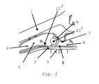
- FIG Fig. 2 A second embodiment of a housing structure according to the invention is shown in FIG Fig. 2 shown.
- the embodiment of the Fig. 2 is largely identical to the embodiment of the Fig. 1 , so that the same components are provided with the same reference numerals and a repeated description of these components is omitted. It is thus only on the differences of the embodiment of Fig. 2 with respect to the embodiment of the Fig. 1 received.
- the main difference of the embodiment of the Fig. 2 compared to the embodiment of the Fig. 1 lies in the form of the mechanical seal 10.
- a semicircular shaped wire element 10 ' is used, wherein in the illustration of Fig. 2
- the cross-sectional shape of the wire element 10 is dashed Fig. 1 is shown.
- the mechanical seal can have any cross-sectional shapes that can be adapted to the given boundary conditions, so that in certain environmental conditions rectangular, square, polygonal or other freely shaped cross-sectional shapes, but also in the circumferential direction changing cross-sectional shapes are conceivable.
- a radially protruding bracket 11 ' which in the embodiment of the Fig. 2 is arranged on the side of the inner wall, while in the embodiment of the Fig. 1 the holder 11 protrudes from the outside inwards.
- the holder 11 ' may be designed as a separate component or integrated into adjacent components.
Landscapes
- Engineering & Computer Science (AREA)
- Mechanical Engineering (AREA)
- General Engineering & Computer Science (AREA)
- Turbine Rotor Nozzle Sealing (AREA)
- Sealing Devices (AREA)
Abstract
Description
- Die vorliegende Erfindung betrifft eine Gehäusestruktur für eine Strömungsmaschine, die einen Strömungskanal für ein Fluid umgibt, das den Strömungskanal durchströmt. Die Gehäusestruktur umfasst eine äußere Gehäusewand und eine den Strömungskanal begrenzenden Innenwand, wobei zwischen Innenwand und äußerer Gehäusewand ein Hohlraum ausgebildet ist. Außerdem betrifft die vorliegende Erfindung eine entsprechende Strömungsmaschine, wie eine stationäre Gasturbine oder ein Flugtriebwerk.
- Strömungsmaschinen, wie stationäre Gasturbinen oder Flugtriebwerke, sind aus dem Stand der Technik bekannt und werden in vielfacher Weise eingesetzt. Entsprechend sind viele Komponenten von Strömungsmaschinen bereits weit entwickelt und weisen vielfältige aufeinander angepasste Eigenschaftsprofile auf.
- Dies gilt auch für die Gehäusestrukturen von Strömungsmaschinen, die den vielfältigen Aufgaben hinsichtlich des Abbaus bzw. der Aufnahme von Druck- und Temperaturunterschieden zwischen dem Strömungskanal der Strömungsmaschine, in dem das Betriebsfluid, wie Luft und Verbrennungsgase, geführt werden, und der äußeren Umgebung genügen müssen.
- Allerdings sind für derartige Gehäusestrukturen ständig weitere Verbesserungen erforderlich, da insbesondere zur Verbesserung der Effizienz höhere Anforderungen an entsprechende Bauteile bzw. Bauteilkonstruktionen gestellt werden.
- So werden beispielsweise in Gehäusestrukturen Dicht- und Isolierelemente eingesetzt, die jedoch einem Verschleiß unterliegen. Insbesondere bei schnell laufenden Niederdruckturbinen in Strömungsmaschinen, die zur Steigerung der Effizienz verstärkt eingesetzt werden, unterliegen die Dicht- und Isolierelementen in der Gehäusestruktur aufgrund der höheren Druckbelastungen einem verstärkten Verschleiß. Es ist deshalb wünschenswert, hier Abhilfe zu schaffen, da bei einem hohen Verschleiß der Bauteile durch den Austausch der verschlissenen Bauteile hohe Kosten, insbesondere hohe Wartungskosten, entstehen.
- Es ist deshalb Aufgabe der vorliegenden Erfindung, eine Gehäusestruktur zu schaffen, bei der der Verschleiß von Komponenten der Gehäusestruktur insbesondere im Bereich von Niederdruckturbinen verringert wird. Gleichwohl soll die Gehäusestruktur jedoch einfach aufgebaut sein und ihre übrigen Aufgaben zuverlässig erfüllen.
- Diese Aufgabe wird gelöst durch eine Gehäusestruktur mit den Merkmalen des Anspruchs 1 sowie einer Strömungsmaschine mit den Merkmalen des Anspruchs 12. Vorteilhafte Ausgestaltungen sind Gegenstand der abhängigen Ansprüche.
- Die Erfindung schlägt vor, in einer Gehäusestruktur mit einer äußeren Gehäusewand und einer den Strömungskanal begrenzenden Innenwand, wobei zwischen Innenwand und äußerer Gehäusewand ein Hohlraum ausgebildet ist, den Hohlraum mit einem Dichtelement abtrennbar, insbesondere in axialer Richtung der Strömungsmaschine abtrennbar, auszugestalten, um unterschiedliche Druckverhältnisse in dem Hohlraum zu ermöglichen. Die Abtrennung soll insbesondere im Bereich einer sogenannten Outer-Air-Seal, also in einem Dichtbereich zwischen den Laufschaufelspitzen und der Innenwand der Gehäusestruktur, ermöglicht werden.
- Dabei soll ein bewegliches Drahtelement als Abtrennung bzw. Dichtelement in dem Hohlraum angeordnet sein, welches gegen Anlageflächen bzw. Dichtflächen anliegen kann, um die Abtrennung bzw. Dichtung zu bewirken. Unter der Beweglichkeit des Drahtelements wird hierbei verstanden, dass das Drahtelement sich als Körper selbst bewegen kann, also translatorisch oder drehend bewegt wird, oder dass eine Bewegung durch eine Bewegung von zumindest von Teilen des Drahtelements durch eine Verformung des Drahtelements stattfindet.
- Mit einer derartigen Konstruktion hat sich gezeigt, dass der Verschleiß von Komponenten in der Gehäusestruktur deutlich reduziert werden kann. Das bewegliche Drahtelement wird dabei in dem Hohlraum nicht fest eingespannt und angeordnet, sondern ist in gewissen Grenzen beweglich, um die unterschiedlichen Druck- und Temperaturverhältnisse während des Betriebs aufnehmen zu können und sich an die umgebenden Komponenten anpassen zu können.
- Das bewegliche Drahtelement kann zumindest teilweise umlaufend um den Strömungskanal ausgebildet sein, wobei insbesondere eine vollständig umlaufende Anordnung vorteilhaft ist, um über den gesamten Umfang der Gehäusestruktur die Dichtwirkung bereitstellen zu können.
- Entsprechend kann das bewegliche Drahtelement, welches auch als Gleitringdichtung bezeichnet werden kann, insbesondere ringförmig ausgebildet sein. Allerdings kann die Gleitringdichtung bzw. das bewegliche Drahtelement um eine Verformbarkeit bzw. Beweglichkeit in Umfangsrichtung zu ermöglichen mindestens einmal geschlitzt sein, das heißt in Umfangsrichtung unterbrochen ausgeführt sein.
- Zusätzlich oder alternativ kann das Drahtelement aus einem elastischen Werkstoff gebildet sein, der bei den Betriebsbedingungen eine elastische Verformung des beweglichen Drahtelements ermöglicht, um eine Anpassung an benachbarte Komponenten und insbesondere Anlageflächen, die zur Ausbildung einer Dichtung vorgesehen sind, zu ermöglichen.
- Insbesondere kann die Gehäusestruktur so ausgebildet sein, dass der Hohlraum eine Querschnittsverengung aufweist, an der zumindest teilweise die Anlageflächen ausgebildet sind, die zusammen mit den beweglichen Drahtelement die Dichtung bilden.
- Das bewegliche Drahtelement bzw. die Gleitringdichtung und somit auch die Querschnittsverengung des Hohlraums können in einem Bereich der Gehäusestruktur angeordnet sein, der dem Bereich entspricht, in dem im Strömungskanal ein Anstreifbelag zum Zusammenwirken mit den Laufschaufelspitzen angeordnet ist. Anders ausgedrückt kann das bewegliche Drahtelement im Bereich einer sogenannten Outer-Air-Seal angeordnet sein, da in diesem Bereich besonders hohe Druckunterschiede auftreten können, die entsprechend durch die Gleitringdichtung in der Gehäusestruktur abgefangen werden können.
- Die Gleitringdichtung kann einen beliebigen Querschnitt aufweisen, wie beispielsweise einen kreisförmigen oder halbkreisförmigen oder mehreckigen Querschnitt. Die Form des Querschnitt kann durch die benachbarten Komponenten beeinflusst sein. Darüber hinaus kann die Gleitringdichtung als Vollkörper oder als Hohlkörper ausgebildet sein, also beispielsweise im Querschnitt als Vollzylinder oder als Hohlzylinder ausgebildet sein.
- Die Beweglichkeit der Gleitringdichtung kann insbesondere in axialer und/oder Umfangsrichtung vorgesehen sein, wobei die Beweglichkeit in Umfangsrichtung einerseits eine Drehung um die Längsachse des Strömungskanals, als auch eine Längendehnung bzw. Umfangsaufweitung umfassen kann. Die Beweglichkeit in axialer Richtung kann eine axiale Verschiebung sowie eine Verformung in axialer Richtung, beispielsweise eine elastische Verformung beim Anpressen an die Anlageflächen, beinhalten.
- Die Bewegung der Gleitringdichtung wird durch die benachbarten Bauteile begrenzt. Unter Betriebslast wird die Bewegung insofern eingeschränkt, dass das Dichtelement immer an die zwei winkelig zueinander stehenden Dichtflächen gedrückt wird. Bewegungen der zwei Dichtflächen zueinander können somit auch von dem Dichtelement ausgeglichen werden.
- Um die axiale Verschiebung der Gleitringdichtung zu begrenzen, kann in dem Hohlraum, in dem die Gleitringdichtung angeordnet ist, mindestens ein radial in den Hohlraum vorstehendes Halteelement vorgesehen sein, sodass die Verschiebungsstrecke für die Gleitringdichtung begrenzt werden kann.
- Die beigefügten Zeichnungen zeigen in rein schematischer Weise in
- Fig. 1
- eine teilweise Schnittansicht einer ersten Ausführungsform einer erfindungsgemäßen Gehäusestruktur; und in
- Fig. 2
- eine teilweise Schnittansicht einer zweiten Ausführungsform einer erfindungsgemäßen Gehäusestruktur.
- Weitere Vorteile, Kennzeichen und Merkmale der vorliegenden Erfindung werden bei der nachfolgenden detaillierten Beschreibung der Ausführungsbeispiele deutlich. Allerdings ist die Erfindung nicht auf diese Ausführungsbeispiele beschränkt.
- Die
Fig. 1 zeigt in einer teilweisen Schnittansicht eine Gehäusestruktur eines Flugtriebwerks mit einer äußeren Gehäusewand 1 und einer Innenwand 2, die umlaufend um einen Strömungskanal angeordnet sind, in denen das Fluid der Strömungsmaschine, also beispielsweise die Verbrennungsgase eines Flugtriebwerks geführt werden, um Laufschaufeln anzutreiben. - Die Laufschaufeln (nicht gezeigt) sind mit ihren Spitzen so angeordnet, dass zwischen der Innenseite der Innenwand 2 und den Spitzen der Laufschaufeln möglichst kein oder nur ein geringer Spalt vorhanden ist, um Antriebsverluste für die Laufschaufeln durch seitliches Vorbeiströmen der Verbrennungsgase zu vermeiden. Entsprechend ist an der Innenwand 2, die auch als sogenanntes Liner - Segment bezeichnet werden kann, vorzugsweise ein Anstreifbelag 3 angeordnet, der in Kontakt mit den Spitzen der Laufschaufel ist, um ein sogenanntes Outer-Air-Seal (OAS) zu bilden. Durch den Antrieb der Laufschaufeln ergibt sich im Strömungskanal zwischen der Eingangsseite der Laufschaufeln und der Ausgangsseite der Laufschaufeln ein Druckunterschied.
- Die Gehäusestruktur umfasst neben der Innenwand 2 eine äußere Gehäusewand 1 sowie dazwischen angeordnete Elemente, wie Hitzeschutzbleche, Isolierelemente oder Hohlräume 4, und hat die Aufgabe die Druck- und Temperaturunterschiede zwischen dem Strömungskanal und der äußeren Umgebung beim Betrieb der Strömungsmaschine abzubauen bzw. aufzunehmen. Ein entsprechender Hohlraum 4 kann beispielsweise zur Führung von Kühlluft und zur Aufnahme entsprechender Bauteile dienen, um die Temperaturdifferenz zwischen Außenseite der Außenwand und Innenseite der Innenwand realisieren zu können.
- Im Bereich des Anstreifbelags bzw. im Bereich der Laufschaufeln, die im Strömungskanal einen entsprechenden Druckabfall bewirken, wird erfindungsgemäß der Hohlraum 4 ebenfalls in zwei Bereiche 5 und 6 unterteilt, in denen entsprechend den Druckverhältnissen im Strömungskanal unterschiedliche Druckverhältnisse p1 und p2 eingestellt werden sollen, um beispielsweise den Einzug von Heißgas aus dem Strömungskanal über Stöße, die an der segmentweise aufgebauten Innenwand 2 auftreten, zu verhindern. Insbesondere bei schnell laufenden Niederdruckturbinen treten im Bereich der Outer-Air-Seal große Druckunterschiede auf, die mit einer entsprechenden Abdichtung der abtrennbaren Bereiche 5 und 6 abgefangen werden können.
- Bei dem gezeigten Ausführungsbeispiel der
Fig. 1 ist deshalb im Hohlraum 4 zwischen den abtrennbaren Bereichen 5 und 6 eine Einbuchtung 7 ausgebildet, die zu einer Querschnittsverminderung des Hohlraums 4 führt, sodass an der Einbuchtung 7 ein bewegliches Drahtelement 10, eine sogenannte Gleitringdichtung, angeordnet werden kann, die gegen Anlageflächen 8 und 9 anliegen kann, die zum einen an der Einbuchtung 7 und zum anderen an der Innenwand 2 oder einem daran angeordneten Hitzeschutzblech oder dergleichen ausgebildet sind. Da der Druck p 1 bei einer Strömungsrichtung des Fluids bzw. Heißgases inFig. 1 von links nach rechts größer ist als der Druck p2, wird die Gleitringdichtung 10 automatisch gegen die Anlageflächen 8 und 9 gepresst, um so eine Abtrennung der Bereiche 5 und 6 sowie eine Abdichtung dieser Bereiche zu bewirken. - Im gezeigten Ausführungsbeispiel ist der Querschnitt des Drahtelements kreisförmig und das Drahtelement ist als Vollkörper ausgebildet, also in Form eines gekrümmten Vollzylinders bzw. Torus.
- Das Drahtelement 10 ist genauso wie die Innenwand 2 bzw. die äußere Gehäusewand 1 und die dazwischen vorgesehenen Bauteile umlaufend um den Strömungskanal angeordnet, sodass die Gleitringdichtung bzw. das Drahtelement 10 eine Ringform aufweisen kann.
- Allerdings kann der Ring in Umfangsrichtung eine Unterbrechung aufweisen, um zu ermöglichen, dass der Ring sich in Umfangsrichtung ausweiten und zusammenziehen kann, d.h. dass er sich bewegen kann. Dies ist vorteilhaft, um die im Betrieb auftretenden Temperaturschwankungen und die sich daraus ergebenden Längenänderungen zu kompensieren.
- Darüber hinaus ist eine Beweglichkeit der Gleitringdichtung 10 in axialer Richtung, also bei der Darstellung der
Fig. 1 von links nach rechts und umgekehrt, gegeben, um eine Verspannung der Gleitringdichtung 10 zu vermeiden und eine freie selbständige Anlage an die Anlageflächen 8,9 je nach Betriebszustand der Strömungsanlage zu ermöglichen. Darüber hinaus kann die Gleitringdichtung 10 aus einem insbesondere bei den Betriebsbedingungen elastischen Material, wie beispielsweise einem elastischen, metallischen Material, gebildet sein, um eine einfache Verformbarkeit zu ermöglichen, die in vorteilhafter Weise dazu führt, dass die Gleitringdichtung 10 sich an die umgebenden Bauteile und insbesondere die Anlageflächen 8, 9 anpassen kann. - Da das bewegliche Drahtelement bzw. die Gleitringdichtung 10 nicht fixiert angeordnet ist, sondern insbesondere in axialer Richtung und in Umfangsrichtung zumindest eine gewisse freie Beweglichkeit aufweist, ist in dem Hohlraum 4 eine sich radial in den Hohlraum 4 erstreckende Halterung 11 vorgesehen, die die axiale Beweglichkeit der Gleitringdichtung 10 beschränkt und die Gleitringdichtung 10 am Einsatzort hält. Diese Halterung 11 kann als separates Bauteil oder integriert in benachbarte Bauteile ausgeführt sein.
- Eine zweite Ausführungsform einer erfindungsgemäßen Gehäusestruktur ist in
Fig. 2 gezeigt. Die Ausführungsform derFig. 2 ist in weiten Teilen identisch zur Ausführungsform derFig. 1 , sodass gleiche Komponenten mit den gleichen Bezugszeichen versehen sind und auf eine wiederholte Beschreibung dieser Komponenten verzichtet wird. Es wird somit lediglich auf die Unterschiede der Ausführungsform derFig. 2 in Bezug auf die Ausführungsform derFig. 1 eingegangen. - Der wesentliche Unterschied der Ausführungsform der
Fig. 2 gegenüber der Ausführungsform derFig. 1 liegt in der Form der Gleitringdichtung 10. Statt eines beweglichen Drahtelements mit einem vollzylindrischen Querschnitt, wie inFig. 1 , wird bei der Ausführungsform derFig. 2 ein halbkreisförmig geformtes Drahtelement 10' eingesetzt, wobei in der Darstellung derFig. 2 zusätzlich strichliniert die Querschnittsform des Drahtelements 10 ausFig. 1 dargestellt ist. - Neben den gezeigten Querschnittsformen kann die Gleitringdichtung beliebige Querschnittsformen aufweisen, die an die vorgegebenen Randbedingungen angepasst sein können, sodass in bestimmten Umgebungsbedingungen rechteckige, quadratische, mehreckige oder sonstige frei geformten Querschnittsformen, aber auch in Umfangsrichtung wechselnde Querschnittsformen denkbar sind.
- Ein weiterer Unterschied der Ausführungsform der
Fig. 2 gegenüber der Ausführungsform derFig. 1 ist bezüglich der radial hervorstehenden Halterung 11' gegeben, die bei der Ausführungsform derFig. 2 an der Seite der Innenwand angeordnet ist, während bei der Ausführungsform derFig. 1 die Halterung 11 von der Außenseite nach innen hervorsteht. Auch hier kann die Halterung 11' als separates Bauteil oder integriert in benachbarte Bauteile ausgeführt sein. - Obwohl die vorliegende Erfindung anhand der Ausführungsbeispiele detailliert beschrieben worden ist, ist für den Fachmann selbstverständlich, dass die Erfindung nicht auf diese beschränkt ist, sondern dass vielmehr Abwandlungen in der Weise möglich sind, dass einzelne Merkmale weggelassen oder andersartige Kombinationen von Merkmalen verwirklicht werden können, solange der Schutzbereich der beigefügten Ansprüche nicht verlassen wird. Die vorliegende Offenbarung umfasst sämtliche Kombinationen der vorgestellten Einzelmerkmale.
Claims (14)
- Gehäusestruktur für eine Strömungsmaschine, die einen Strömungskanal für ein Fluid umgibt, mit einer äußeren Gehäusewand (1) und einer den Strömungskanal begrenzenden Innenwand, wobei zwischen Innenwand (2) und äußerer Gehäusewand ein Hohlraum (4) ausgebildet ist,
dadurch gekennzeichnet, dass
der Hohlraum in mindestens zwei Bereiche (5,6) abtrennbar ist, wobei zur Abtrennung ein bewegliches Drahtelement (10,10') in dem Hohlraum angeordnet ist, welches gegen Anlageflächen (8,9) anliegen kann. - Gehäusestruktur nach Anspruch 1,
dadurch gekennzeichnet, dass
das bewegliche Drahtelement ( 10,10') zumindest teilweise umlaufend um den Strömungskanal ausgebildet ist. - Gehäusestruktur nach Anspruch 1 oder 2,
dadurch gekennzeichnet, dass
das bewegliche Drahtelement (10,10') ringförmig ausgebildet ist. - Gehäusestruktur nach einem der vorhergehenden Ansprüche,
dadurch gekennzeichnet, dass
das bewegliche Drahtelement (10,10') so ausgebildet ist, dass es verformbar ist. - Gehäusestruktur nach Anspruch 4,
dadurch gekennzeichnet, dass
das bewegliche Drahtelement (10,10') ein geschlitzter Ring ist und/oder aus einem elastischen Werkstoff gebildet ist. - Gehäusestruktur nach einem der vorhergehenden Ansprüche,
dadurch gekennzeichnet, dass
der Hohlraum (4) eine Querschnittsverengung (7) aufweist, an der zumindest teilweise die Anlageflächen ausgebildet sind. - Gehäusestruktur nach einem der vorhergehenden Ansprüche,
dadurch gekennzeichnet, dass
an der Innenwand ein Anstreifbelag (3) für Schaufelspitzen vorgesehen ist, wobei das bewegliche Drahtelement (10,10') im Bereich des Anstreifbelags auf der gegenüber liegenden, abgewandten Seite der Innenwand (2) angeordnet ist. - Gehäusestruktur nach einem der vorhergehenden Ansprüche,
dadurch gekennzeichnet, dass
das bewegliche Drahtelement (10,10') einen kreisförmigen oder halbkreisförmigen oder mehreckigen Querschnitt aufweist und/oder als Vollkörper oder als Hohlkörper ausgebildet ist. - Gehäusestruktur nach einem der vorhergehenden Ansprüche,
dadurch gekennzeichnet, dass
der Hohlraum (4) mindestens ein radial in den Hohlraum vorstehendes Halteelement (11,11') umfasst, welches die axiale Beweglichkeit des beweglichen Drahtelements begrenzt. - Gehäusestruktur nach einem der vorhergehenden Ansprüche,
dadurch gekennzeichnet, dass
das bewegliche Drahtelement (10,10') in axialer und/oder Umfangsrichtung beweglich ist. - Gehäusestruktur nach einem der vorhergehenden Ansprüche,
dadurch gekennzeichnet, dass
das bewegliche Drahtelement (10,10')im Betrieb der Strömungsmaschine durch Druckunterschiede in den abtrennbaren Bereichen des Hohlraums gegen die Anlageflächen gedrückt wird. - Strömungsmaschine mit einer Gehäusestruktur nach einem der vorhergehenden Ansprüche.
- Strömungsmaschine nach Anspruch 12,
dadurch gekennzeichnet, dass
die Strömungsmaschine eine stationäre Gasturbine oder ein Flugtriebwerk ist. - Strömungsmaschine nach Anspruch 12 oder 13,
dadurch gekennzeichnet, dass
die Gehäusestruktur im Bereich der Niederdruckturbine angeordnet ist.
Priority Applications (3)
| Application Number | Priority Date | Filing Date | Title |
|---|---|---|---|
| EP13165101.0A EP2796667B1 (de) | 2013-04-24 | 2013-04-24 | Gleitringdichtung |
| ES13165101.0T ES2679343T3 (es) | 2013-04-24 | 2013-04-24 | Junta de estanqueidad deslizante |
| US14/249,056 US9835039B2 (en) | 2013-04-24 | 2014-04-09 | Slide ring seal |
Applications Claiming Priority (1)
| Application Number | Priority Date | Filing Date | Title |
|---|---|---|---|
| EP13165101.0A EP2796667B1 (de) | 2013-04-24 | 2013-04-24 | Gleitringdichtung |
Publications (2)
| Publication Number | Publication Date |
|---|---|
| EP2796667A1 true EP2796667A1 (de) | 2014-10-29 |
| EP2796667B1 EP2796667B1 (de) | 2018-06-27 |
Family
ID=48182784
Family Applications (1)
| Application Number | Title | Priority Date | Filing Date |
|---|---|---|---|
| EP13165101.0A Not-in-force EP2796667B1 (de) | 2013-04-24 | 2013-04-24 | Gleitringdichtung |
Country Status (3)
| Country | Link |
|---|---|
| US (1) | US9835039B2 (de) |
| EP (1) | EP2796667B1 (de) |
| ES (1) | ES2679343T3 (de) |
Citations (4)
| Publication number | Priority date | Publication date | Assignee | Title |
|---|---|---|---|---|
| US3656862A (en) * | 1970-07-02 | 1972-04-18 | Westinghouse Electric Corp | Segmented seal assembly |
| EP0937864A2 (de) * | 1998-02-20 | 1999-08-25 | Mtu Motoren- Und Turbinen-Union MàNchen Gmbh | Leitschaufelanordnung für eine axiale Strömungsmaschine |
| EP0940562A2 (de) * | 1998-03-03 | 1999-09-08 | Mitsubishi Heavy Industries, Ltd. | Gasturbine |
| US20050232752A1 (en) * | 2004-04-15 | 2005-10-20 | David Meisels | Turbine shroud cooling system |
-
2013
- 2013-04-24 EP EP13165101.0A patent/EP2796667B1/de not_active Not-in-force
- 2013-04-24 ES ES13165101.0T patent/ES2679343T3/es active Active
-
2014
- 2014-04-09 US US14/249,056 patent/US9835039B2/en not_active Expired - Fee Related
Patent Citations (4)
| Publication number | Priority date | Publication date | Assignee | Title |
|---|---|---|---|---|
| US3656862A (en) * | 1970-07-02 | 1972-04-18 | Westinghouse Electric Corp | Segmented seal assembly |
| EP0937864A2 (de) * | 1998-02-20 | 1999-08-25 | Mtu Motoren- Und Turbinen-Union MàNchen Gmbh | Leitschaufelanordnung für eine axiale Strömungsmaschine |
| EP0940562A2 (de) * | 1998-03-03 | 1999-09-08 | Mitsubishi Heavy Industries, Ltd. | Gasturbine |
| US20050232752A1 (en) * | 2004-04-15 | 2005-10-20 | David Meisels | Turbine shroud cooling system |
Also Published As
| Publication number | Publication date |
|---|---|
| US20140321969A1 (en) | 2014-10-30 |
| ES2679343T3 (es) | 2018-08-24 |
| EP2796667B1 (de) | 2018-06-27 |
| US9835039B2 (en) | 2017-12-05 |
Similar Documents
| Publication | Publication Date | Title |
|---|---|---|
| EP2960438B1 (de) | Leitschaufelvorrichtung für eine gasturbine sowie gasturbine mit einer solchen leitschaufelvorrichtung | |
| EP2466074A1 (de) | Gasturbinentriebwerk mit Kolbenringdichtung | |
| EP3153667B1 (de) | Sicherungsvorrichtung zur axialen sicherung einer laufschaufel und rotorvorrichtung mit einer derartigen sicherungsvorrichtung | |
| EP3152407B1 (de) | Leitschaufelkranz, innenring und strömungsmaschine | |
| EP2728122B1 (de) | Dichtungsträgerfixierung für eine Strömungsmaschine | |
| EP2884054A1 (de) | Verstellbare Leitschaufel mit Kegelstumpf in einer Lageranordnung | |
| EP3032148B1 (de) | Axialer wellendichtring | |
| EP2696037A1 (de) | Abdichtung des Strömungskanals einer Strömungsmaschine | |
| EP3179053B1 (de) | Gehäusestruktur einer strömungsmaschine mit hitzeschutzschild | |
| EP3613952B1 (de) | Verstellbare leitschaufelanordnung, leitschaufel, dichtungsträger und turbomaschine | |
| EP2871325A1 (de) | Innenring einer Strömungsmaschine und Leitrad | |
| EP2955336B1 (de) | Zwischengehäuse für eine Gasturbine sowie Gasturbine mit einem solchen Zwischengehäuse | |
| EP2173974B1 (de) | Hitzeschildsegment für einen stator einer gasturbine | |
| EP3208426B1 (de) | Leitschaufelsegment für eine strömungsmaschine | |
| EP3121385B1 (de) | Rotorvorrichtung eines flugtriebwerks mit einer dämpfungseinrichtung zwischen laufschaufeln | |
| EP3159505B1 (de) | Zwischengehàuse für eine gasturbine | |
| EP2526263B1 (de) | Gehäusesystem für eine axialströmungsmaschine | |
| EP2826956A1 (de) | Rotor für eine thermische Strömungsmaschine | |
| WO2014207058A1 (de) | Dichtringsegment für einen stator einer turbine | |
| EP2947282B1 (de) | Zwischengehäuse für eine Gasturbine sowie Gasturbine | |
| DE102009052314A1 (de) | Dichtanordnung für eine Gasturbine und eine derartige Gasturbine | |
| DE102010036071A1 (de) | Gehäuseseitige Struktur einer Turbomaschine | |
| EP2796667B1 (de) | Gleitringdichtung | |
| DE102013203870B4 (de) | Verdrehsicherung für Turbomaschinen | |
| EP2719867B1 (de) | Gehäusestruktur mit verbesserter Abdichtung und Kühlung |
Legal Events
| Date | Code | Title | Description |
|---|---|---|---|
| PUAI | Public reference made under article 153(3) epc to a published international application that has entered the european phase |
Free format text: ORIGINAL CODE: 0009012 |
|
| 17P | Request for examination filed |
Effective date: 20130424 |
|
| AK | Designated contracting states |
Kind code of ref document: A1 Designated state(s): AL AT BE BG CH CY CZ DE DK EE ES FI FR GB GR HR HU IE IS IT LI LT LU LV MC MK MT NL NO PL PT RO RS SE SI SK SM TR |
|
| AX | Request for extension of the european patent |
Extension state: BA ME |
|
| R17P | Request for examination filed (corrected) |
Effective date: 20150409 |
|
| RBV | Designated contracting states (corrected) |
Designated state(s): AL AT BE BG CH CY CZ DE DK EE ES FI FR GB GR HR HU IE IS IT LI LT LU LV MC MK MT NL NO PL PT RO RS SE SI SK SM TR |
|
| RAP1 | Party data changed (applicant data changed or rights of an application transferred) |
Owner name: MTU AERO ENGINES AG |
|
| RIC1 | Information provided on ipc code assigned before grant |
Ipc: F01D 11/12 20060101ALI20171009BHEP Ipc: F01D 25/26 20060101ALI20171009BHEP Ipc: F01D 11/02 20060101ALI20171009BHEP Ipc: F01D 25/24 20060101ALI20171009BHEP Ipc: F01D 11/00 20060101AFI20171009BHEP |
|
| GRAP | Despatch of communication of intention to grant a patent |
Free format text: ORIGINAL CODE: EPIDOSNIGR1 |
|
| STAA | Information on the status of an ep patent application or granted ep patent |
Free format text: STATUS: GRANT OF PATENT IS INTENDED |
|
| GRAJ | Information related to disapproval of communication of intention to grant by the applicant or resumption of examination proceedings by the epo deleted |
Free format text: ORIGINAL CODE: EPIDOSDIGR1 |
|
| STAA | Information on the status of an ep patent application or granted ep patent |
Free format text: STATUS: REQUEST FOR EXAMINATION WAS MADE |
|
| INTG | Intention to grant announced |
Effective date: 20171130 |
|
| INTC | Intention to grant announced (deleted) | ||
| GRAP | Despatch of communication of intention to grant a patent |
Free format text: ORIGINAL CODE: EPIDOSNIGR1 |
|
| STAA | Information on the status of an ep patent application or granted ep patent |
Free format text: STATUS: GRANT OF PATENT IS INTENDED |
|
| INTG | Intention to grant announced |
Effective date: 20180306 |
|
| GRAS | Grant fee paid |
Free format text: ORIGINAL CODE: EPIDOSNIGR3 |
|
| GRAA | (expected) grant |
Free format text: ORIGINAL CODE: 0009210 |
|
| STAA | Information on the status of an ep patent application or granted ep patent |
Free format text: STATUS: THE PATENT HAS BEEN GRANTED |
|
| AK | Designated contracting states |
Kind code of ref document: B1 Designated state(s): AL AT BE BG CH CY CZ DE DK EE ES FI FR GB GR HR HU IE IS IT LI LT LU LV MC MK MT NL NO PL PT RO RS SE SI SK SM TR |
|
| REG | Reference to a national code |
Ref country code: GB Ref legal event code: FG4D Free format text: NOT ENGLISH |
|
| REG | Reference to a national code |
Ref country code: AT Ref legal event code: REF Ref document number: 1012538 Country of ref document: AT Kind code of ref document: T Effective date: 20180715 |
|
| REG | Reference to a national code |
Ref country code: IE Ref legal event code: FG4D Free format text: LANGUAGE OF EP DOCUMENT: GERMAN |
|
| REG | Reference to a national code |
Ref country code: DE Ref legal event code: R096 Ref document number: 502013010461 Country of ref document: DE |
|
| REG | Reference to a national code |
Ref country code: ES Ref legal event code: FG2A Ref document number: 2679343 Country of ref document: ES Kind code of ref document: T3 Effective date: 20180824 |
|
| PG25 | Lapsed in a contracting state [announced via postgrant information from national office to epo] |
Ref country code: FI Free format text: LAPSE BECAUSE OF FAILURE TO SUBMIT A TRANSLATION OF THE DESCRIPTION OR TO PAY THE FEE WITHIN THE PRESCRIBED TIME-LIMIT Effective date: 20180627 Ref country code: BG Free format text: LAPSE BECAUSE OF FAILURE TO SUBMIT A TRANSLATION OF THE DESCRIPTION OR TO PAY THE FEE WITHIN THE PRESCRIBED TIME-LIMIT Effective date: 20180927 Ref country code: LT Free format text: LAPSE BECAUSE OF FAILURE TO SUBMIT A TRANSLATION OF THE DESCRIPTION OR TO PAY THE FEE WITHIN THE PRESCRIBED TIME-LIMIT Effective date: 20180627 Ref country code: NO Free format text: LAPSE BECAUSE OF FAILURE TO SUBMIT A TRANSLATION OF THE DESCRIPTION OR TO PAY THE FEE WITHIN THE PRESCRIBED TIME-LIMIT Effective date: 20180927 Ref country code: SE Free format text: LAPSE BECAUSE OF FAILURE TO SUBMIT A TRANSLATION OF THE DESCRIPTION OR TO PAY THE FEE WITHIN THE PRESCRIBED TIME-LIMIT Effective date: 20180627 |
|
| REG | Reference to a national code |
Ref country code: NL Ref legal event code: MP Effective date: 20180627 |
|
| REG | Reference to a national code |
Ref country code: LT Ref legal event code: MG4D |
|
| PG25 | Lapsed in a contracting state [announced via postgrant information from national office to epo] |
Ref country code: RS Free format text: LAPSE BECAUSE OF FAILURE TO SUBMIT A TRANSLATION OF THE DESCRIPTION OR TO PAY THE FEE WITHIN THE PRESCRIBED TIME-LIMIT Effective date: 20180627 Ref country code: HR Free format text: LAPSE BECAUSE OF FAILURE TO SUBMIT A TRANSLATION OF THE DESCRIPTION OR TO PAY THE FEE WITHIN THE PRESCRIBED TIME-LIMIT Effective date: 20180627 Ref country code: GR Free format text: LAPSE BECAUSE OF FAILURE TO SUBMIT A TRANSLATION OF THE DESCRIPTION OR TO PAY THE FEE WITHIN THE PRESCRIBED TIME-LIMIT Effective date: 20180928 Ref country code: LV Free format text: LAPSE BECAUSE OF FAILURE TO SUBMIT A TRANSLATION OF THE DESCRIPTION OR TO PAY THE FEE WITHIN THE PRESCRIBED TIME-LIMIT Effective date: 20180627 |
|
| PG25 | Lapsed in a contracting state [announced via postgrant information from national office to epo] |
Ref country code: NL Free format text: LAPSE BECAUSE OF FAILURE TO SUBMIT A TRANSLATION OF THE DESCRIPTION OR TO PAY THE FEE WITHIN THE PRESCRIBED TIME-LIMIT Effective date: 20180627 |
|
| PG25 | Lapsed in a contracting state [announced via postgrant information from national office to epo] |
Ref country code: SK Free format text: LAPSE BECAUSE OF FAILURE TO SUBMIT A TRANSLATION OF THE DESCRIPTION OR TO PAY THE FEE WITHIN THE PRESCRIBED TIME-LIMIT Effective date: 20180627 Ref country code: PL Free format text: LAPSE BECAUSE OF FAILURE TO SUBMIT A TRANSLATION OF THE DESCRIPTION OR TO PAY THE FEE WITHIN THE PRESCRIBED TIME-LIMIT Effective date: 20180627 Ref country code: CZ Free format text: LAPSE BECAUSE OF FAILURE TO SUBMIT A TRANSLATION OF THE DESCRIPTION OR TO PAY THE FEE WITHIN THE PRESCRIBED TIME-LIMIT Effective date: 20180627 Ref country code: RO Free format text: LAPSE BECAUSE OF FAILURE TO SUBMIT A TRANSLATION OF THE DESCRIPTION OR TO PAY THE FEE WITHIN THE PRESCRIBED TIME-LIMIT Effective date: 20180627 Ref country code: EE Free format text: LAPSE BECAUSE OF FAILURE TO SUBMIT A TRANSLATION OF THE DESCRIPTION OR TO PAY THE FEE WITHIN THE PRESCRIBED TIME-LIMIT Effective date: 20180627 Ref country code: IS Free format text: LAPSE BECAUSE OF FAILURE TO SUBMIT A TRANSLATION OF THE DESCRIPTION OR TO PAY THE FEE WITHIN THE PRESCRIBED TIME-LIMIT Effective date: 20181027 |
|
| PG25 | Lapsed in a contracting state [announced via postgrant information from national office to epo] |
Ref country code: SM Free format text: LAPSE BECAUSE OF FAILURE TO SUBMIT A TRANSLATION OF THE DESCRIPTION OR TO PAY THE FEE WITHIN THE PRESCRIBED TIME-LIMIT Effective date: 20180627 Ref country code: IT Free format text: LAPSE BECAUSE OF FAILURE TO SUBMIT A TRANSLATION OF THE DESCRIPTION OR TO PAY THE FEE WITHIN THE PRESCRIBED TIME-LIMIT Effective date: 20180627 |
|
| REG | Reference to a national code |
Ref country code: DE Ref legal event code: R097 Ref document number: 502013010461 Country of ref document: DE |
|
| PLBE | No opposition filed within time limit |
Free format text: ORIGINAL CODE: 0009261 |
|
| STAA | Information on the status of an ep patent application or granted ep patent |
Free format text: STATUS: NO OPPOSITION FILED WITHIN TIME LIMIT |
|
| PG25 | Lapsed in a contracting state [announced via postgrant information from national office to epo] |
Ref country code: DK Free format text: LAPSE BECAUSE OF FAILURE TO SUBMIT A TRANSLATION OF THE DESCRIPTION OR TO PAY THE FEE WITHIN THE PRESCRIBED TIME-LIMIT Effective date: 20180627 |
|
| 26N | No opposition filed |
Effective date: 20190328 |
|
| PG25 | Lapsed in a contracting state [announced via postgrant information from national office to epo] |
Ref country code: SI Free format text: LAPSE BECAUSE OF FAILURE TO SUBMIT A TRANSLATION OF THE DESCRIPTION OR TO PAY THE FEE WITHIN THE PRESCRIBED TIME-LIMIT Effective date: 20180627 |
|
| REG | Reference to a national code |
Ref country code: DE Ref legal event code: R119 Ref document number: 502013010461 Country of ref document: DE |
|
| PG25 | Lapsed in a contracting state [announced via postgrant information from national office to epo] |
Ref country code: AL Free format text: LAPSE BECAUSE OF FAILURE TO SUBMIT A TRANSLATION OF THE DESCRIPTION OR TO PAY THE FEE WITHIN THE PRESCRIBED TIME-LIMIT Effective date: 20180627 |
|
| REG | Reference to a national code |
Ref country code: CH Ref legal event code: PL |
|
| REG | Reference to a national code |
Ref country code: BE Ref legal event code: MM Effective date: 20190430 |
|
| GBPC | Gb: european patent ceased through non-payment of renewal fee |
Effective date: 20190424 |
|
| PG25 | Lapsed in a contracting state [announced via postgrant information from national office to epo] |
Ref country code: MC Free format text: LAPSE BECAUSE OF FAILURE TO SUBMIT A TRANSLATION OF THE DESCRIPTION OR TO PAY THE FEE WITHIN THE PRESCRIBED TIME-LIMIT Effective date: 20180627 Ref country code: LU Free format text: LAPSE BECAUSE OF NON-PAYMENT OF DUE FEES Effective date: 20190424 |
|
| PG25 | Lapsed in a contracting state [announced via postgrant information from national office to epo] |
Ref country code: DE Free format text: LAPSE BECAUSE OF NON-PAYMENT OF DUE FEES Effective date: 20191101 Ref country code: LI Free format text: LAPSE BECAUSE OF NON-PAYMENT OF DUE FEES Effective date: 20190430 Ref country code: CH Free format text: LAPSE BECAUSE OF NON-PAYMENT OF DUE FEES Effective date: 20190430 Ref country code: GB Free format text: LAPSE BECAUSE OF NON-PAYMENT OF DUE FEES Effective date: 20190424 |
|
| PG25 | Lapsed in a contracting state [announced via postgrant information from national office to epo] |
Ref country code: BE Free format text: LAPSE BECAUSE OF NON-PAYMENT OF DUE FEES Effective date: 20190430 Ref country code: FR Free format text: LAPSE BECAUSE OF NON-PAYMENT OF DUE FEES Effective date: 20190430 |
|
| PG25 | Lapsed in a contracting state [announced via postgrant information from national office to epo] |
Ref country code: TR Free format text: LAPSE BECAUSE OF FAILURE TO SUBMIT A TRANSLATION OF THE DESCRIPTION OR TO PAY THE FEE WITHIN THE PRESCRIBED TIME-LIMIT Effective date: 20180627 |
|
| PG25 | Lapsed in a contracting state [announced via postgrant information from national office to epo] |
Ref country code: IE Free format text: LAPSE BECAUSE OF NON-PAYMENT OF DUE FEES Effective date: 20190424 |
|
| PG25 | Lapsed in a contracting state [announced via postgrant information from national office to epo] |
Ref country code: PT Free format text: LAPSE BECAUSE OF FAILURE TO SUBMIT A TRANSLATION OF THE DESCRIPTION OR TO PAY THE FEE WITHIN THE PRESCRIBED TIME-LIMIT Effective date: 20181029 |
|
| REG | Reference to a national code |
Ref country code: AT Ref legal event code: MM01 Ref document number: 1012538 Country of ref document: AT Kind code of ref document: T Effective date: 20190424 |
|
| REG | Reference to a national code |
Ref country code: ES Ref legal event code: FD2A Effective date: 20200831 |
|
| PG25 | Lapsed in a contracting state [announced via postgrant information from national office to epo] |
Ref country code: ES Free format text: LAPSE BECAUSE OF NON-PAYMENT OF DUE FEES Effective date: 20190425 |
|
| PG25 | Lapsed in a contracting state [announced via postgrant information from national office to epo] |
Ref country code: AT Free format text: LAPSE BECAUSE OF NON-PAYMENT OF DUE FEES Effective date: 20190424 |
|
| PG25 | Lapsed in a contracting state [announced via postgrant information from national office to epo] |
Ref country code: CY Free format text: LAPSE BECAUSE OF FAILURE TO SUBMIT A TRANSLATION OF THE DESCRIPTION OR TO PAY THE FEE WITHIN THE PRESCRIBED TIME-LIMIT Effective date: 20180627 |
|
| PG25 | Lapsed in a contracting state [announced via postgrant information from national office to epo] |
Ref country code: HU Free format text: LAPSE BECAUSE OF FAILURE TO SUBMIT A TRANSLATION OF THE DESCRIPTION OR TO PAY THE FEE WITHIN THE PRESCRIBED TIME-LIMIT; INVALID AB INITIO Effective date: 20130424 Ref country code: MT Free format text: LAPSE BECAUSE OF FAILURE TO SUBMIT A TRANSLATION OF THE DESCRIPTION OR TO PAY THE FEE WITHIN THE PRESCRIBED TIME-LIMIT Effective date: 20180627 |
|
| PG25 | Lapsed in a contracting state [announced via postgrant information from national office to epo] |
Ref country code: MK Free format text: LAPSE BECAUSE OF FAILURE TO SUBMIT A TRANSLATION OF THE DESCRIPTION OR TO PAY THE FEE WITHIN THE PRESCRIBED TIME-LIMIT Effective date: 20180627 |