EP2796030A1 - Multi-blade mower deck with mulch/side discharge conversion - Google Patents
Multi-blade mower deck with mulch/side discharge conversion Download PDFInfo
- Publication number
- EP2796030A1 EP2796030A1 EP20140165841 EP14165841A EP2796030A1 EP 2796030 A1 EP2796030 A1 EP 2796030A1 EP 20140165841 EP20140165841 EP 20140165841 EP 14165841 A EP14165841 A EP 14165841A EP 2796030 A1 EP2796030 A1 EP 2796030A1
- Authority
- EP
- European Patent Office
- Prior art keywords
- mulch
- mower deck
- side discharge
- cutting chamber
- baffle
- Prior art date
- Legal status (The legal status is an assumption and is not a legal conclusion. Google has not performed a legal analysis and makes no representation as to the accuracy of the status listed.)
- Withdrawn
Links
Images


Classifications
-
- A—HUMAN NECESSITIES
- A01—AGRICULTURE; FORESTRY; ANIMAL HUSBANDRY; HUNTING; TRAPPING; FISHING
- A01D—HARVESTING; MOWING
- A01D42/00—Mowers convertible to apparatus for purposes other than mowing; Mowers capable of performing operations other than mowing
- A01D42/005—Mulching
Definitions
- This invention relates to mower decks and, more specifically, multi-blade mower decks with mulch/side discharge conversion.
- Multi-blade mower decks with mulch/side discharge conversion have been designed and offered as kits or original equipment for converting between side discharge and mulching positions.
- mulch kits may include one or more baffles that may be installed under the deck.
- Some mower decks also include hinged baffles that may be pivoted between side discharge and mulching positions.
- US Patent 6,609,358 entitled “Mower Having a Mower Deck Adapted for Selective Mulching or Non-Mulching Modes” relates to a multi-blade mower deck with hinged baffles that may pivot from a side discharge position to a mulching position.
- a multi-blade mower deck with mulch/side discharge conversion includes a mulch gate and a baffle positioned adjacent each other under a mower deck. In a mulching position, the mulch gate and baffle block a flow path from the mower deck out a front right side of the mower deck.
- a handle on the mower deck may be used to move at least one of the mulch gate and the baffle between the mulching position and a side discharge position to partially open the flow path.
- the multi-blade mower deck with mulch/side discharge conversion is relatively quick and easy to install or remove, has fewer parts than existing devices, is low in cost, and provides good side discharge and mulching capabilities.
- multi-blade mower deck with mulch/side discharge conversion 100 may include three adjacent cutting chambers 101, 102, 103, with each cutting chamber covering or housing a rotary cutting blade 104, 105, 106.
- the cutting blades may be mounted and secured to the lower ends of generally vertically oriented spindles for rotation on vertical axes.
- the spindles may be rotated by one or more belts wound around pulleys attached to the upper ends of the spindles.
- mower deck 100 may have skirt 107 extending downwardly around at least a portion of the outer periphery of top surface 108 of the mower deck.
- Vertical baffle 109 may be welded or otherwise attached to the underside of the mower deck forwardly of the cutting chambers at a location to the rear of the front skirt.
- Gauge wheels may be attached to the skirt and/or periphery of the mower deck to help prevent or minimize damage or scalping of the ground surface or turf when mowing.
- mower deck 100 may provide mulch/side discharge conversion in the form of mulch kit 120.
- Mulch kit 120 may include left front deflector plate or baffle 121 and right front deflector plate or baffle 122.
- Each of the pair of front deflector plates or baffles may be releasably fastened and/or secured to the underside 123 of the mower deck.
- Each of the pair of front deflector plates or baffles may extend downwardly from the underside of the mower deck at least partially around the front of at least two of the cutting chambers.
- the pair of front deflector plates or baffles may be joined together to form a one-piece deflector plate.
- the left and right front deflector plates may abut each other or may be adjacent to each other at or near the front of cutting chamber 102.
- mulch kit 120 also may include a plurality of clips 125 or other similar fasteners that may be welded or attached to each front deflector plate or baffle and may be spring biased to releasably hold each front deflector plate or baffle against or next to vertical baffle 109 or, alternatively, to the front skirt of the mower deck. Additionally, the mulch kit may include a plurality of threaded studs 126 that may be attached to or engaged to horizontal flanges 127 at the front of the deflector plate(s).
- Each threaded stud 126 may be used to secure a front deflector plate to the mower deck by inserting the threaded stud through a hole between the underside and top surface of the deck, and securing the threaded stud with a nut or fastener 139.
- the use of clips 125 minimizes the quantity of other hardware, e.g., threaded fasteners, sufficient to attach and secure each front deflector plate to the mower deck.
- mulch kit 120 may include left front deflector plate or baffle 121 that extends down from the underside of the mower deck at least partially around the front of the perimeter of left cutting chamber 101, and at least partially around the front of the perimeter of center cutting chamber 102.
- Mulch kit 120 also may include right front deflector plate or baffle 122 that extends down from the underside of the mower deck partially at least partially around the front of the perimeter of center cutting chamber 102, and at least partially around the front of the perimeter of right cutting chamber 103.
- Each of the front deflector plates or baffles may have a curved or arced surface and may extend down from the underside of the deck to a horizontal plane below the plane of the cutting blades.
- mulch kit 120 also may include baffle 135 that extends down from the underside of the mower deck at least partially closing the discharge chute at the right side of the perimeter of right cutting chamber 103.
- baffle 135 may be removably secured to the underside of the mower deck baffle so that the baffle blocks that portion of the flow passage FP1 that is rearwardly of the spindle for cutting blade 106.
- Baffle 135 may be secured to the underside of the deck with a threaded stud.
- mulch kit 120 may include mulch gate 130 which may be a hinged baffle attached to vertically oriented hinge 132 at the right edge of right front deflector plate or baffle 122.
- mulch gate 130 In the mulching position shown in Fig. 1 , mulch gate 130 may extend at least partially around the front and right of the perimeter of the first or right cutting chamber 103. In the mulching position, mulch gate 130 may abut discharge chute baffle 135 on the side of the first or right cutting chamber, to close or block flow passage FP1 from the first or right cutting chamber out through an opening in side skirt 107 at the side of the mower deck and under side discharge deflector 137.
- mulch kit 120 may include mulch gate 130 that may swing or pivot forwardly from the mulching position to the side discharge position adjacent front skirt 107 at the front of the mower deck, as shown in Fig. 2 .
- flow passage FP1 In the side discharge position, flow passage FP1 is open from first or right cutting chamber 103 out through an opening in the side skirt at the side of the mower deck and under side discharge deflector 137.
- the open portion of flow passage FP1 may be between hinged baffle or mulch gate 130 and discharge chute baffle 135.
- the open portion of flow passage FP1 may be limited to less than about 45 degrees around the circumference of the first or right cutting chamber.
- mulch gate 130 may remain covered by and under the mower deck.
- a discharge chute may be attached to the side of the mower deck for collection of grass clippings.
- the discharge chute also may include an impeller or fan.
- mulch kit 120 may include front deflector plates or baffles 121, 122 that are configured and positioned to provide openings for grass clippings to move between each of the cutting chambers.
- the openings may be located between the front deflector plates and one or more baffles 140 at or adjacent the rear of the cutting chambers.
- the openings may promote flow of grass clippings from the left cutting chamber to the second or center cutting chamber, and from the second or center cutting chamber to the first or right cutting chamber.
- the openings may be limited to less than about 45 degrees around the circumference of each cutting chamber.
- mulch kit 120 may include mulch gate handle or lever 137 that an operator may use to open and close hinged baffle or mulch gate 130.
- the mulch gate lever may be located on top of the deck above the first or right cutting chamber and may be connected to and pivot on the vertical axis of hinge 132.
- the mulch gate lever may be biased to the mulching position and/or the side discharge position.
- over center tension spring 138 may be attached between the mulch gate lever and fastener 139 on top of the mower deck, to urge the hinged baffle or mulch gate to either the mulching position or the side discharge position.
- An actuator also may be provided on the mower deck adjacent the mulch gate lever, and the actuator may be mechanically or electrically connected to a control in the vehicle's operator station so that a seated operator may pivot the mulch gate lever between a mulching position and a side discharge position.
- multi-blade mower deck with mulch/side discharge conversion 200 may include adjacent cutting chambers 201, 202, with each cutting chamber covering or housing a rotary cutting blade 204, 205.
- An opening may be provided between the left and right cutting chambers.
- the cutting blades may be mounted and secured to the lower ends of generally vertically oriented spindles for rotation on vertical axes.
- the spindles may be turned by one or more belts wound around pulleys attached to the upper ends of the spindles.
- mower deck 200 may have skirt 207 extending downwardly around at least a portion of the outer periphery of top surface 208 of the mower deck. Gauge wheels may be attached to the skirt and/or periphery of the mower deck to help prevent or minimize damage or scalping of the ground surface or turf when mowing.
- mower deck 200 may include mulch gate 222 which may be a hinged or pivoting baffle attached to vertical hinge 223 under the mower deck adjacent a front or forward portion of the first or right cutting chamber.
- baffle 224 may extend down from the underside of the mower deck at least partially closing the flow path FP2 at the side of the perimeter of the first or right cutting chamber 202.
- baffle 224 may abut edge 238 of side skirt 207 on the side of the first or right cutting chamber, blocking that portion of the flow passage FP2 that is rearwardly of the spindle for cutting blade 205.
- mulch gate 222 and baffle 224 may close or block flow passage FP2 from the first or right cutting chamber out through an opening in the side skirt from the mower deck and under side discharge deflector 230.
- baffle 224 may pivot on horizontal hinge 225 from the mulching position of Fig. 4 to a side discharge position of Fig. 5 .
- mulch gate 222 may swing or pivot forwardly away from the middle of the first or right cutting chamber to a location adjacent front skirt 207 at the front of the mower deck.
- baffle 224 may swing or pivot upwardly on a horizontal pivot axis that is perpendicular to the vertical pivot axis of mulch gate 222.
- flow passage FP2 may be opened from first or right cutting chamber 202 out through a side skirt of the mower deck and under side discharge deflector 230.
- flow passage FP2 may be limited to less than about 45 degrees around the circumference of the first or right cutting chamber.
- mower deck 200 may be operated with flow passage FP2 only partially open, by moving mulch gate 222 and baffle 224 to positions between the mulching position and the side discharge position. Additionally, as shown in Fig. 6 , mower deck 200 may be operated with flow passage FP2 fully open and bagging chute 231 covering the opening in the side of the mower deck. To operate the mower deck in the collection or bagging position, mulch gate 222 may swing or pivot fully forward to a location adjacent front skirt 207 at the front of the mower deck, and baffle 224 may swing or pivot upwardly away from the first or right cutting chamber. Bagging chute 231 may then be attached and secured to the mower deck by engaging a flange or surface of the bagging chute between the top of the mower deck and a portion of the first mulch gate or horizontal hinge.
- mower deck 200 may be moved between each position using mulch gate handle or lever 232 supported by bracket 233 attached to the skirt 207 on the side of the mower deck.
- Mulch gate handle or lever 232 may be a U-shaped lever having a first end engaged and secured to the hinge pin of horizontal hinge 225.
- a middle portion of mulch gate handle or lever 232 may be pivotably attached to rod or linkage 235.
- the rod or linkage may be pivotably attached to lever 236, which may be connected to the hinge pin of vertical hinge 223.
- the mulch gate handle may pivot the mulch gate and baffle at the same time between the mulching, side discharge and bagging positions.
- An actuator also may be provided on the mower deck adjacent the mulch gate handle, and the actuator may be mechanically or electrically connected to a control in the vehicle's operator station so that a seated operator may pivot the mulch gate handle between the mulching position, side discharge position, and collection or bagging position.
- multi-blade mower deck with mulch/side discharge conversion 300 may include adjacent cutting chambers 301, 302, with each cutting chamber covering or housing a rotary cutting blade 304, 305.
- An opening may be provided between the left and right cutting chambers.
- the cutting blades may be mounted and secured to the lower ends of generally vertically oriented spindles for rotation on vertical axes.
- the spindles may be turned by one or more belts wound around pulleys attached to the upper ends of the spindles.
- mower deck 300 may have skirt 307 extending downwardly around at least a portion of the outer periphery of top surface 308 of the mower deck. Gauge wheels may be attached to the skirt and/or periphery of the mower deck to help prevent or minimize damage or scalping of the ground surface or turf when mowing.
- mower deck 300 may include mulch gate 322.
- Mulch gate 322 may be a sliding baffle attached to pin or rod 325 at an outer end of pivot arm 324 at or adjacent the top 308 of the mower deck over the spindle in the first or right cutting chamber.
- mulch gate 322 in the mulching position shown in Fig. 7 , mulch gate 322 may extend at least partially around the front and side of the perimeter of first or right cutting chamber 302. In the mulching position, mulch gate 322 may slide generally horizontally to a position adjacent or abutting edge 338 of side skirt 307 on the side of the first or right cutting chamber. In the mulching position, the mulch gate may close or block flow passage FP3 from the first or right cutting chamber out from the mower deck under side discharge deflector 330.
- mulch gate 322 may slide horizontally rearwardly around the outer surface on the side of the perimeter of the first or right cutting chamber, to a location behind and adjacent the side of the first or right cutting chamber.
- flow passage FP3 is open from first or right cutting chamber 302 out from the mower deck under side discharge deflector 330.
- flow passage FP3 may be limited to less than about 45 degrees around the circumference of the first or right cutting chamber.
- the mower deck with mulch/side discharge conversion may be operated with flow passage FP3 only partially open, by moving mulch gate 322 to a position between the mulching position and the side discharge position.
- an actuator, lever or arm may be provided on the mower deck adjacent pivot member 324, and the actuator may be connected by Bowden cable 333 to control 332 in the vehicle's operator station so that a seated operator may move the pivot member between a mulching position and a side discharge position.
Landscapes
- Life Sciences & Earth Sciences (AREA)
- Environmental Sciences (AREA)
- Harvester Elements (AREA)
Abstract
Description
- This invention relates to mower decks and, more specifically, multi-blade mower decks with mulch/side discharge conversion.
- Multi-blade mower decks with mulch/side discharge conversion have been designed and offered as kits or original equipment for converting between side discharge and mulching positions. For example, mulch kits may include one or more baffles that may be installed under the deck. Some mower decks also include hinged baffles that may be pivoted between side discharge and mulching positions. For example,
US Patent 6,609,358 entitled "Mower Having a Mower Deck Adapted for Selective Mulching or Non-Mulching Modes" relates to a multi-blade mower deck with hinged baffles that may pivot from a side discharge position to a mulching position. However, there is a need for a multi-blade mower deck with mulch/side discharge conversion that is relatively quick and easy to install or remove as a kit, with fewer parts than existing devices. There also is a need for a multi-blade mower deck with mulch/side discharge conversion that is low in cost, and provides good side discharge and mulching capabilities. - A multi-blade mower deck with mulch/side discharge conversion includes a mulch gate and a baffle positioned adjacent each other under a mower deck. In a mulching position, the mulch gate and baffle block a flow path from the mower deck out a front right side of the mower deck. A handle on the mower deck may be used to move at least one of the mulch gate and the baffle between the mulching position and a side discharge position to partially open the flow path.
- The multi-blade mower deck with mulch/side discharge conversion is relatively quick and easy to install or remove, has fewer parts than existing devices, is low in cost, and provides good side discharge and mulching capabilities.
-
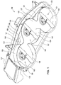
Fig. 1 is a bottom perspective view of a multi-blade mower deck with mulch/side discharge conversion according to a first embodiment of the invention, in a mulching position. -
Fig. 2 is a bottom perspective view of a multi-blade mower deck with mulch/side discharge conversion according to a first embodiment of the invention, in a side discharge position. -
Fig. 3 is a top perspective view of a multi-blade mower deck with mulch/side discharge conversion according to a first embodiment of the invention. -
Fig. 4 is a bottom perspective view of a multi-blade mower deck with mulch/side discharge conversion according to a second embodiment of the invention, in a mulching position. -
Fig. 5 is a bottom perspective view of a multi-blade mower deck with mulch/side discharge conversion according to a second embodiment of the invention, in a side discharge position. -
Fig. 6 is a top perspective view of a multi-blade mower deck with mulch/side discharge conversion according to a second embodiment of the invention, in a collection or bagging position. -
Fig. 7 is a bottom perspective view of a multi-blade mower deck with mulch/side discharge conversion according to a third embodiment of the invention, in a mulching position. -
Fig.8 is a top perspective view of a multi-blade mower deck with mulch/side discharge conversion according to a third embodiment of the invention, in a side discharge position. -
Fig. 9 is a top perspective view of a multi-blade mower deck with mulch/side discharge conversion according to a third embodiment of the invention, in a side discharge position. - In a first embodiment shown in
Figs. 1-3 , multi-blade mower deck with mulch/side discharge conversion 100 may include threeadjacent cutting chambers rotary cutting blade - In a first embodiment,
mower deck 100 may have skirt 107 extending downwardly around at least a portion of the outer periphery oftop surface 108 of the mower deck.Vertical baffle 109 may be welded or otherwise attached to the underside of the mower deck forwardly of the cutting chambers at a location to the rear of the front skirt. Gauge wheels may be attached to the skirt and/or periphery of the mower deck to help prevent or minimize damage or scalping of the ground surface or turf when mowing. - In a first embodiment,
mower deck 100 may provide mulch/side discharge conversion in the form ofmulch kit 120.Mulch kit 120 may include left front deflector plate orbaffle 121 and right front deflector plate orbaffle 122. Each of the pair of front deflector plates or baffles may be releasably fastened and/or secured to theunderside 123 of the mower deck. Each of the pair of front deflector plates or baffles may extend downwardly from the underside of the mower deck at least partially around the front of at least two of the cutting chambers. Alternatively, the pair of front deflector plates or baffles may be joined together to form a one-piece deflector plate. In the first embodiment showing a pair of front deflector plates, the left and right front deflector plates may abut each other or may be adjacent to each other at or near the front ofcutting chamber 102. - In a first embodiment,
mulch kit 120 also may include a plurality ofclips 125 or other similar fasteners that may be welded or attached to each front deflector plate or baffle and may be spring biased to releasably hold each front deflector plate or baffle against or next tovertical baffle 109 or, alternatively, to the front skirt of the mower deck. Additionally, the mulch kit may include a plurality of threadedstuds 126 that may be attached to or engaged tohorizontal flanges 127 at the front of the deflector plate(s). Each threadedstud 126 may be used to secure a front deflector plate to the mower deck by inserting the threaded stud through a hole between the underside and top surface of the deck, and securing the threaded stud with a nut orfastener 139. The use ofclips 125 minimizes the quantity of other hardware, e.g., threaded fasteners, sufficient to attach and secure each front deflector plate to the mower deck. - In a first embodiment,
mulch kit 120 may include left front deflector plate orbaffle 121 that extends down from the underside of the mower deck at least partially around the front of the perimeter ofleft cutting chamber 101, and at least partially around the front of the perimeter ofcenter cutting chamber 102.Mulch kit 120 also may include right front deflector plate orbaffle 122 that extends down from the underside of the mower deck partially at least partially around the front of the perimeter ofcenter cutting chamber 102, and at least partially around the front of the perimeter ofright cutting chamber 103. Each of the front deflector plates or baffles may have a curved or arced surface and may extend down from the underside of the deck to a horizontal plane below the plane of the cutting blades. - In a first embodiment,
mulch kit 120 also may includebaffle 135 that extends down from the underside of the mower deck at least partially closing the discharge chute at the right side of the perimeter ofright cutting chamber 103. For example,baffle 135 may be removably secured to the underside of the mower deck baffle so that the baffle blocks that portion of the flow passage FP1 that is rearwardly of the spindle for cuttingblade 106. Baffle 135 may be secured to the underside of the deck with a threaded stud. - In a first embodiment,
mulch kit 120 may includemulch gate 130 which may be a hinged baffle attached to verticallyoriented hinge 132 at the right edge of right front deflector plate orbaffle 122. In the mulching position shown inFig. 1 ,mulch gate 130 may extend at least partially around the front and right of the perimeter of the first orright cutting chamber 103. In the mulching position,mulch gate 130 may abutdischarge chute baffle 135 on the side of the first or right cutting chamber, to close or block flow passage FP1 from the first or right cutting chamber out through an opening inside skirt 107 at the side of the mower deck and underside discharge deflector 137. - In a first embodiment,
mulch kit 120 may includemulch gate 130 that may swing or pivot forwardly from the mulching position to the side discharge position adjacentfront skirt 107 at the front of the mower deck, as shown inFig. 2 . In the side discharge position, flow passage FP1 is open from first orright cutting chamber 103 out through an opening in the side skirt at the side of the mower deck and underside discharge deflector 137. The open portion of flow passage FP1 may be between hinged baffle ormulch gate 130 anddischarge chute baffle 135. Preferably, in the side discharge position, the open portion of flow passage FP1 may be limited to less than about 45 degrees around the circumference of the first or right cutting chamber. In both the mulching and the side discharge positions,mulch gate 130 may remain covered by and under the mower deck. Optionally, a discharge chute may be attached to the side of the mower deck for collection of grass clippings. The discharge chute also may include an impeller or fan. - In a first embodiment,
mulch kit 120 may include front deflector plates orbaffles more baffles 140 at or adjacent the rear of the cutting chambers. The openings may promote flow of grass clippings from the left cutting chamber to the second or center cutting chamber, and from the second or center cutting chamber to the first or right cutting chamber. Preferably, the openings may be limited to less than about 45 degrees around the circumference of each cutting chamber. - In a first embodiment,
mulch kit 120 may include mulch gate handle orlever 137 that an operator may use to open and close hinged baffle ormulch gate 130. The mulch gate lever may be located on top of the deck above the first or right cutting chamber and may be connected to and pivot on the vertical axis ofhinge 132. The mulch gate lever may be biased to the mulching position and/or the side discharge position. For example, overcenter tension spring 138 may be attached between the mulch gate lever and fastener 139 on top of the mower deck, to urge the hinged baffle or mulch gate to either the mulching position or the side discharge position. An actuator also may be provided on the mower deck adjacent the mulch gate lever, and the actuator may be mechanically or electrically connected to a control in the vehicle's operator station so that a seated operator may pivot the mulch gate lever between a mulching position and a side discharge position. - In a second embodiment shown in
Figs. 4-6 , multi-blade mower deck with mulch/side discharge conversion 200 may includeadjacent cutting chambers rotary cutting blade - In a second embodiment,
mower deck 200 may haveskirt 207 extending downwardly around at least a portion of the outer periphery oftop surface 208 of the mower deck. Gauge wheels may be attached to the skirt and/or periphery of the mower deck to help prevent or minimize damage or scalping of the ground surface or turf when mowing. - In a second embodiment,
mower deck 200 may includemulch gate 222 which may be a hinged or pivoting baffle attached tovertical hinge 223 under the mower deck adjacent a front or forward portion of the first or right cutting chamber. Additionally, in the mulching position ofFig. 4 , baffle 224 may extend down from the underside of the mower deck at least partially closing the flow path FP2 at the side of the perimeter of the first or right cuttingchamber 202. For example, in the mulching position ofFig. 4 , baffle 224 may abut edge 238 ofside skirt 207 on the side of the first or right cutting chamber, blocking that portion of the flow passage FP2 that is rearwardly of the spindle for cuttingblade 205. In the mulching position,mulch gate 222 and baffle 224 may close or block flow passage FP2 from the first or right cutting chamber out through an opening in the side skirt from the mower deck and underside discharge deflector 230. - In a second embodiment, baffle 224 may pivot on
horizontal hinge 225 from the mulching position ofFig. 4 to a side discharge position ofFig. 5 . As shown inFig. 5 ,mulch gate 222 may swing or pivot forwardly away from the middle of the first or right cutting chamber to a location adjacentfront skirt 207 at the front of the mower deck. Optionally, baffle 224 may swing or pivot upwardly on a horizontal pivot axis that is perpendicular to the vertical pivot axis ofmulch gate 222. Thus, in the side discharge position, flow passage FP2 may be opened from first or right cuttingchamber 202 out through a side skirt of the mower deck and underside discharge deflector 230. Preferably, flow passage FP2 may be limited to less than about 45 degrees around the circumference of the first or right cutting chamber. - In a second embodiment,
mower deck 200 may be operated with flow passage FP2 only partially open, by movingmulch gate 222 and baffle 224 to positions between the mulching position and the side discharge position. Additionally, as shown inFig. 6 ,mower deck 200 may be operated with flow passage FP2 fully open and baggingchute 231 covering the opening in the side of the mower deck. To operate the mower deck in the collection or bagging position,mulch gate 222 may swing or pivot fully forward to a location adjacentfront skirt 207 at the front of the mower deck, and baffle 224 may swing or pivot upwardly away from the first or right cutting chamber. Baggingchute 231 may then be attached and secured to the mower deck by engaging a flange or surface of the bagging chute between the top of the mower deck and a portion of the first mulch gate or horizontal hinge. - In a second embodiment,
mower deck 200 may be moved between each position using mulch gate handle or lever 232 supported bybracket 233 attached to theskirt 207 on the side of the mower deck. Mulch gate handle or lever 232 may be a U-shaped lever having a first end engaged and secured to the hinge pin ofhorizontal hinge 225. A middle portion of mulch gate handle or lever 232 may be pivotably attached to rod orlinkage 235. The rod or linkage may be pivotably attached to lever 236, which may be connected to the hinge pin ofvertical hinge 223. The mulch gate handle may pivot the mulch gate and baffle at the same time between the mulching, side discharge and bagging positions. An actuator also may be provided on the mower deck adjacent the mulch gate handle, and the actuator may be mechanically or electrically connected to a control in the vehicle's operator station so that a seated operator may pivot the mulch gate handle between the mulching position, side discharge position, and collection or bagging position. - In a third embodiment shown in
Figs. 7-9 , multi-blade mower deck with mulch/side discharge conversion 300 may includeadjacent cutting chambers rotary cutting blade - In a third embodiment,
mower deck 300 may haveskirt 307 extending downwardly around at least a portion of the outer periphery oftop surface 308 of the mower deck. Gauge wheels may be attached to the skirt and/or periphery of the mower deck to help prevent or minimize damage or scalping of the ground surface or turf when mowing. - In a third embodiment,
mower deck 300 may includemulch gate 322.Mulch gate 322 may be a sliding baffle attached to pin orrod 325 at an outer end ofpivot arm 324 at or adjacent the top 308 of the mower deck over the spindle in the first or right cutting chamber. - In a third embodiment, in the mulching position shown in
Fig. 7 ,mulch gate 322 may extend at least partially around the front and side of the perimeter of first or right cuttingchamber 302. In the mulching position,mulch gate 322 may slide generally horizontally to a position adjacent or abuttingedge 338 ofside skirt 307 on the side of the first or right cutting chamber. In the mulching position, the mulch gate may close or block flow passage FP3 from the first or right cutting chamber out from the mower deck underside discharge deflector 330. - In a third embodiment, in the side discharge position shown in
Fig. 8 ,mulch gate 322 may slide horizontally rearwardly around the outer surface on the side of the perimeter of the first or right cutting chamber, to a location behind and adjacent the side of the first or right cutting chamber. In the side discharge position, flow passage FP3 is open from first or right cuttingchamber 302 out from the mower deck underside discharge deflector 330. Preferably, flow passage FP3 may be limited to less than about 45 degrees around the circumference of the first or right cutting chamber. The mower deck with mulch/side discharge conversion may be operated with flow passage FP3 only partially open, by movingmulch gate 322 to a position between the mulching position and the side discharge position. - In a third embodiment, an actuator, lever or arm may be provided on the mower deck
adjacent pivot member 324, and the actuator may be connected byBowden cable 333 to control 332 in the vehicle's operator station so that a seated operator may move the pivot member between a mulching position and a side discharge position.
Claims (5)
- A multi-blade mower deck with mulch/side discharge conversion, comprising:a mulch gate mounted under the mower deck and connected to a vertical hinge under the mower deck at the front of a first cutting chamber, the mulch gate extending rearwardly around a portion of a perimeter of the first cutting chamber to a location adjacent the first cutting chamber in a mulching position;a mulch gate lever on top of the mower deck and connected to the vertical hinge and pivoting the mulch gate between the mulching position and a side discharge position in which the mulch gate is under the mower deck and forwardly of the first cutting chamber; anda baffle mounted under the mower deck and extending forwardly from a location adjacent a side skirt of the first cutting chamber to a location forwardly of a cutting blade spindle in the first cutting chamber, the baffle blocking a portion of a flow passage through the side skirt of the first cutting chamber.
- The multi-blade mower deck with mulch/side discharge conversion according to claim 1 wherein the baffle pivots on a horizontal hinge.
- The multi-blade mower deck with mulch/side discharge conversion according to claim 1 or 2 wherein the mulch gate lever pivots the mulch gate and the baffle.
- The multi-blade mower deck with mulch/side discharge conversion according to one of the claims 1 to 3 further comprising a spring biasing the mulch gate lever to the mulching position and to the side discharge position.
- The multi-blade mower deck with mulch/side discharge conversion according on of the claims 1 to 4 further comprising a deflector plate removably secured under the mower deck forwardly of a second cutting chamber and a third cutting chamber.
Applications Claiming Priority (1)
| Application Number | Priority Date | Filing Date | Title |
|---|---|---|---|
| US13/871,553 US9485911B2 (en) | 2013-04-26 | 2013-04-26 | Multi-blade mower deck with mulch/side discharge conversion |
Publications (1)
| Publication Number | Publication Date |
|---|---|
| EP2796030A1 true EP2796030A1 (en) | 2014-10-29 |
Family
ID=50542922
Family Applications (1)
| Application Number | Title | Priority Date | Filing Date |
|---|---|---|---|
| EP20140165841 Withdrawn EP2796030A1 (en) | 2013-04-26 | 2014-04-24 | Multi-blade mower deck with mulch/side discharge conversion |
Country Status (2)
| Country | Link |
|---|---|
| US (1) | US9485911B2 (en) |
| EP (1) | EP2796030A1 (en) |
Cited By (1)
| Publication number | Priority date | Publication date | Assignee | Title |
|---|---|---|---|---|
| EP3449711A1 (en) * | 2017-08-25 | 2019-03-06 | Deere & Company | Grass collection chute fastener |
Families Citing this family (19)
| Publication number | Priority date | Publication date | Assignee | Title |
|---|---|---|---|---|
| US9192100B1 (en) * | 2013-05-24 | 2015-11-24 | Jonathan Ullom | Apparatus for clearing matted grass clippings from lawnmower discharge port |
| US9699963B2 (en) * | 2015-06-11 | 2017-07-11 | Deere & Company | Mulch kit control lever |
| WO2019035021A1 (en) * | 2017-08-16 | 2019-02-21 | Briggs & Stratton Corporation | Zero turn radius lawnmower having front and rear wheels related in rotation about a single pivot axis |
| EP3678468B1 (en) | 2017-09-08 | 2024-08-14 | Briggs & Stratton Corporation | Multi-configurable mower deck |
| US10729069B2 (en) * | 2018-02-28 | 2020-08-04 | Angie Condon | Multiple outlet chute lawnmower housing assembly |
| US11470777B2 (en) * | 2018-08-01 | 2022-10-18 | Honda Motor Co., Ltd. | Variable mulching assembly for use with a lawnmower |
| US11503762B2 (en) * | 2018-11-29 | 2022-11-22 | Honda Motor Co., Ltd. | Shutter assembly for a lawnmower, lawnmower having same, and convertible lawnmower |
| US10897845B2 (en) * | 2019-01-28 | 2021-01-26 | Honda Motor Co., Ltd. | Cutter housing assembly for a lawnmower, lawnmower having same, and convertible lawnmower |
| US10966368B2 (en) | 2019-02-20 | 2021-04-06 | Honda Motor Co., Ltd. | Cutter housing assembly for a lawnmower and lawnmower having same |
| US10945366B2 (en) | 2019-03-12 | 2021-03-16 | Honda Motor Co., Ltd. | Cutter housing assembly for a lawnmower, lawnmower having same, and convertible lawnmower |
| US11044846B2 (en) | 2019-04-01 | 2021-06-29 | Honda Motor Co., Ltd. | Cutter housing assembly for a lawnmower, lawnmower having same, and convertible lawnmower |
| US11122738B2 (en) | 2019-04-23 | 2021-09-21 | Honda Motor Co., Ltd. | Cutter housing assembly for a lawnmower, lawnmower having same, and convertible lawnmower |
| US11006573B2 (en) | 2019-05-07 | 2021-05-18 | Honda Motor Co., Ltd. | Cutter housing assembly for a lawnmower, lawnmower having same, and convertible lawnmower |
| US11516965B2 (en) | 2019-09-25 | 2022-12-06 | Deere & Company | Electrically actuated mulch control lever |
| US11716932B2 (en) * | 2020-02-19 | 2023-08-08 | Excel Industries, Inc. | Side-discharge to bagging conversion assembly for mower |
| US12058956B2 (en) * | 2020-09-01 | 2024-08-13 | Deere & Company | Mulch kit control lever |
| US12527253B2 (en) | 2021-06-04 | 2026-01-20 | Speedtrap Chute LLC | Variable chute device for power mower |
| US12250899B2 (en) * | 2021-09-08 | 2025-03-18 | Deere & Company | Mulch gate control lever |
| US20250120340A1 (en) * | 2023-10-12 | 2025-04-17 | Tyrone Pickens | Lawnmower clipping chute assembly |
Citations (3)
| Publication number | Priority date | Publication date | Assignee | Title |
|---|---|---|---|---|
| US6609358B1 (en) | 2002-06-25 | 2003-08-26 | Deere & Company | Mower having a mower deck adapted for selective mulching or non-mulching modes |
| EP1719403A1 (en) * | 2005-05-04 | 2006-11-08 | Deere & Company | Mower deck |
| EP1776858A1 (en) * | 2005-10-19 | 2007-04-25 | Deere & Company | Convertible mower deck |
Family Cites Families (31)
| Publication number | Priority date | Publication date | Assignee | Title |
|---|---|---|---|---|
| US4226074A (en) | 1979-01-08 | 1980-10-07 | Excel Industries, Inc. | Lawnmower deck |
| US5191756A (en) | 1991-02-04 | 1993-03-09 | Deere & Company | Mulching mower apparatus |
| US5179823A (en) | 1991-07-23 | 1993-01-19 | Pace Sang H | Variable mulching mower with edger attachment |
| US5205112A (en) | 1992-03-20 | 1993-04-27 | The Toro Company | Multi-bladed mulching/bagging mower |
| US5499494A (en) | 1993-07-23 | 1996-03-19 | White Consolidated Industries, Inc. | Lawn mower discharge chute |
| US5465564A (en) * | 1994-12-12 | 1995-11-14 | Moridge Manufacturing, Inc. | Convertible mower deck |
| US5845475A (en) * | 1995-11-16 | 1998-12-08 | Exmark Mfg. Co., Inc. | Lawn mower having flow control baffles and removable mulching baffles |
| US5826417A (en) | 1996-12-23 | 1998-10-27 | Magic Circle Corporation | Operator controlled deflector plate for discharge chute of riding lawn mower |
| US6185920B1 (en) | 1998-07-20 | 2001-02-13 | Lonmore L.C. | Zero radius steering, compact stand-on mower and utility tractor |
| US6892519B2 (en) * | 2002-01-14 | 2005-05-17 | Scag Power Equipment, Inc. | Adjustable baffle for mowing deck |
| US6910324B2 (en) | 2002-02-01 | 2005-06-28 | The Toro Company | Multi-bladed rotary cutting deck with mulching and discharge/collection modes |
| JP3771529B2 (en) | 2002-03-26 | 2006-04-26 | 本田技研工業株式会社 | Lawn mower |
| US6874309B1 (en) | 2002-04-04 | 2005-04-05 | William B. Bellis, Jr. | Discharge baffle for lawnmower |
| JP3859562B2 (en) * | 2002-07-10 | 2006-12-20 | 株式会社クボタ | Moore |
| US6857256B2 (en) | 2002-10-25 | 2005-02-22 | Harry R. Strange | Lawn mower chute opening apparatus and method |
| US7093415B2 (en) * | 2003-06-23 | 2006-08-22 | The Toro Company | Lawn mower having adjustable flow control baffle |
| US7146791B2 (en) | 2003-11-03 | 2006-12-12 | Deere & Company | Interchangeable mulching/discharge mowing deck |
| US7367174B2 (en) | 2005-02-18 | 2008-05-06 | The Toro Company | Rotary lawn mower with pivotal mulch door |
| US7337602B1 (en) | 2005-09-15 | 2008-03-04 | Butler Walt R | Mulch plate apparatus with adjustable handle mechanism |
| US7650739B2 (en) | 2005-09-15 | 2010-01-26 | Butler Walter R | Mulch plate apparatus with adjustable handle mechanism |
| US7204073B1 (en) | 2005-09-23 | 2007-04-17 | Deere & Company | Convertible mower deck with interlocking baffles |
| US7406817B2 (en) | 2006-05-10 | 2008-08-05 | Danny Bledsoe | Mower discharge sliding door |
| US7866135B2 (en) * | 2006-08-28 | 2011-01-11 | Exmark Manufacturing Company, Inc. | Flow control baffle for turf mower |
| US7574852B1 (en) | 2006-10-25 | 2009-08-18 | Exmark Mfg. Co., Inc. | Multi-bladed cutting deck with adjustable flow control baffles |
| US7448195B2 (en) | 2006-12-08 | 2008-11-11 | Kohler Gary C | Lawn mower attachment for controlling discharge flow |
| US20090266043A1 (en) * | 2007-08-01 | 2009-10-29 | Shivvers Group Incorporated | New mower deck enhancement |
| US7624562B2 (en) | 2007-08-02 | 2009-12-01 | The Toro Company | Mower cutting deck having operator controlled discharge opening using intuitively operable handle |
| US8156722B2 (en) * | 2008-01-11 | 2012-04-17 | Kubota Corporation | Mower having a grass clippings guide and shield member |
| US7805920B2 (en) | 2008-11-13 | 2010-10-05 | The Toro Company | Lawn mower having steeply inclined exit tunnel and battery access through rear face of mower cutting deck |
| US8104255B1 (en) | 2008-11-13 | 2012-01-31 | The Toro Company | Lawn mower having selectively usable side discharge chute |
| US8171709B1 (en) * | 2010-10-27 | 2012-05-08 | Schiller Grounds Care, Inc. | Mower baffle system |
-
2013
- 2013-04-26 US US13/871,553 patent/US9485911B2/en active Active
-
2014
- 2014-04-24 EP EP20140165841 patent/EP2796030A1/en not_active Withdrawn
Patent Citations (3)
| Publication number | Priority date | Publication date | Assignee | Title |
|---|---|---|---|---|
| US6609358B1 (en) | 2002-06-25 | 2003-08-26 | Deere & Company | Mower having a mower deck adapted for selective mulching or non-mulching modes |
| EP1719403A1 (en) * | 2005-05-04 | 2006-11-08 | Deere & Company | Mower deck |
| EP1776858A1 (en) * | 2005-10-19 | 2007-04-25 | Deere & Company | Convertible mower deck |
Cited By (1)
| Publication number | Priority date | Publication date | Assignee | Title |
|---|---|---|---|---|
| EP3449711A1 (en) * | 2017-08-25 | 2019-03-06 | Deere & Company | Grass collection chute fastener |
Also Published As
| Publication number | Publication date |
|---|---|
| US9485911B2 (en) | 2016-11-08 |
| US20140318099A1 (en) | 2014-10-30 |
Similar Documents
| Publication | Publication Date | Title |
|---|---|---|
| US9485911B2 (en) | Multi-blade mower deck with mulch/side discharge conversion | |
| US9699963B2 (en) | Mulch kit control lever | |
| US6874309B1 (en) | Discharge baffle for lawnmower | |
| US7624562B2 (en) | Mower cutting deck having operator controlled discharge opening using intuitively operable handle | |
| US7677022B2 (en) | Convertible mower deck with angled pivoting baffles | |
| US8065866B2 (en) | Lawn mower pivotable mulching flap | |
| EP1785027B1 (en) | Lawn mower | |
| US8950167B2 (en) | Riding lawn mower | |
| US20040168424A1 (en) | Deck assembly for a self-propelled, walk-behind rotary lawn mower | |
| US9750179B2 (en) | Convertible mower deck with mulch on demand actuator | |
| US20090301050A1 (en) | Lawn mower attachment and method | |
| US6971224B1 (en) | Retractable discharge chute for a lawn mower | |
| US7174700B2 (en) | Mower deck with multiple modes of operation | |
| JP2018530329A (en) | Walking reel lawn mower | |
| US8104255B1 (en) | Lawn mower having selectively usable side discharge chute | |
| US6857256B2 (en) | Lawn mower chute opening apparatus and method | |
| EP3437453B1 (en) | Riding grass-mower | |
| EP3453244B1 (en) | Mower deck discharge chute with drive belt tunnel | |
| EP3266298B1 (en) | Material collection system tube fastener | |
| EP3449711A1 (en) | Grass collection chute fastener | |
| JP5091883B2 (en) | Riding mower | |
| US10798875B2 (en) | Discharge guard assembly for a mower | |
| KR200381266Y1 (en) | Apparatus for moving a driver's seat of riding lawn mower |
Legal Events
| Date | Code | Title | Description |
|---|---|---|---|
| PUAI | Public reference made under article 153(3) epc to a published international application that has entered the european phase |
Free format text: ORIGINAL CODE: 0009012 |
|
| 17P | Request for examination filed |
Effective date: 20140424 |
|
| AK | Designated contracting states |
Kind code of ref document: A1 Designated state(s): AL AT BE BG CH CY CZ DE DK EE ES FI FR GB GR HR HU IE IS IT LI LT LU LV MC MK MT NL NO PL PT RO RS SE SI SK SM TR |
|
| AX | Request for extension of the european patent |
Extension state: BA ME |
|
| R17P | Request for examination filed (corrected) |
Effective date: 20150429 |
|
| RBV | Designated contracting states (corrected) |
Designated state(s): AL AT BE BG CH CY CZ DE DK EE ES FI FR GB GR HR HU IE IS IT LI LT LU LV MC MK MT NL NO PL PT RO RS SE SI SK SM TR |
|
| 17Q | First examination report despatched |
Effective date: 20181030 |
|
| STAA | Information on the status of an ep patent application or granted ep patent |
Free format text: STATUS: THE APPLICATION IS DEEMED TO BE WITHDRAWN |
|
| 18D | Application deemed to be withdrawn |
Effective date: 20190312 |