EP2795369B1 - Formation properties from conductivity tensor - Google Patents
Formation properties from conductivity tensor Download PDFInfo
- Publication number
- EP2795369B1 EP2795369B1 EP12859535.2A EP12859535A EP2795369B1 EP 2795369 B1 EP2795369 B1 EP 2795369B1 EP 12859535 A EP12859535 A EP 12859535A EP 2795369 B1 EP2795369 B1 EP 2795369B1
- Authority
- EP
- European Patent Office
- Prior art keywords
- matrix
- symmetrized
- matrix products
- products
- gain
- Prior art date
- Legal status (The legal status is an assumption and is not a legal conclusion. Google has not performed a legal analysis and makes no representation as to the accuracy of the status listed.)
- Active
Links
Images








Classifications
-
- G—PHYSICS
- G01—MEASURING; TESTING
- G01V—GEOPHYSICS; GRAVITATIONAL MEASUREMENTS; DETECTING MASSES OR OBJECTS; TAGS
- G01V3/00—Electric or magnetic prospecting or detecting; Measuring magnetic field characteristics of the earth, e.g. declination, deviation
- G01V3/18—Electric or magnetic prospecting or detecting; Measuring magnetic field characteristics of the earth, e.g. declination, deviation specially adapted for well-logging
- G01V3/30—Electric or magnetic prospecting or detecting; Measuring magnetic field characteristics of the earth, e.g. declination, deviation specially adapted for well-logging operating with electromagnetic waves
-
- G—PHYSICS
- G01—MEASURING; TESTING
- G01V—GEOPHYSICS; GRAVITATIONAL MEASUREMENTS; DETECTING MASSES OR OBJECTS; TAGS
- G01V3/00—Electric or magnetic prospecting or detecting; Measuring magnetic field characteristics of the earth, e.g. declination, deviation
- G01V3/38—Processing data, e.g. for analysis, for interpretation, for correction
Definitions
- Logging tools have long been used in wellbores to make, for example, formation evaluation measurements to infer properties of the formations surrounding the borehole and the fluids in the formations.
- Common logging tools include electromagnetic tools, nuclear tools, and nuclear magnetic resonance (NMR) tools, though various other tool types are also used.
- NMR nuclear magnetic resonance
- MWD tools sometimes provide drilling parameter information such as weight on the bit, torque, temperature, pressure, direction, and inclination.
- LWD tools sometimes provide formation evaluation measurements such as resistivity, porosity, and NMR distributions.
- MWD and LWD tools often have components common to wireline tools (e.g., transmitting and receiving antennas), but MWD and LWD tools must be constructed to not only endure but to operate in the harsh environment of drilling.
- wireline tools e.g., transmitting and receiving antennas
- MWD and LWD tools must be constructed to not only endure but to operate in the harsh environment of drilling.
- the terms MWD and LWD are often used interchangeably, and the use of either term in this disclosure will be understood to include both the collection of formation and wellbore information, as well as data on movement and placement of the drilling assembly.
- Logging tools can also be used to image a wellbore. For example, measurements of resistivity, density, the photoelectric factor, natural gamma ray radiation, the dielectric constant, and acoustic impedance (e.g., ultrasonics) have been used to form wellbore images. Most, if not all, of those imaging methods are dependent on the type of drilling fluid ("mud") used.
- mud drilling fluid
- WO2011/139761 describes a method for obtaining gain-corrected measurements, comprising: providing a measurement tool having one or more arrays, wherein the arrays comprise two co- located triaxial transmitters and two co-located triaxial receivers; obtaining measurements using the two co-located triaxial transmitters and the two co-located triaxial receivers; forming impedance matrices from the obtained measurements; and combining the impedance matrices to provide gain-corrected measurements.
- US 2011/238312 discloses a logging tool carrying out borehole compensated resistivity measurements.
- the present invention resides in a method as defined in claim 1 and in a logging tool as defined in claim 8.
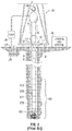
- Figure 1 illustrates a well site system in which various embodiments can be employed.
- the well site can be onshore or offshore.
- a borehole 11 is formed in subsurface formations by rotary drilling in a manner that is well known.
- Some embodiments can also use directional drilling, as will be described hereinafter.
- a drill string 12 is suspended within the borehole 11 and has a bottom hole assembly 100 which includes a drill bit 105 at its lower end.
- the surface system includes platform and derrick assembly 10 positioned over the borehole 11, the assembly 10 including a rotary table 16, kelly 17, hook 18 and rotary swivel 19.
- the drill string 12 is rotated by the rotary table 16, energized by means not shown, which engages the kelly 17 at the upper end of the drill string.
- the drill string 12 is suspended from a hook 18, attached to a traveling block (also not shown), through the kelly 17 and a rotary swivel 19 which permits rotation of the drill string relative to the hook.
- a top drive system could alternatively be used.
- the surface system further includes drilling fluid or mud 26 stored in a pit 27 formed at the well site.
- a pump 29 delivers the drilling fluid 26 to the interior of the drill string 12 via a port in the swivel 19, causing the drilling fluid to flow downwardly through the drill string 12 as indicated by the directional arrow 8.
- the drilling fluid exits the drill string 12 via ports in the drill bit 105, and then circulates upwardly through the annulus region between the outside of the drill string and the wall of the borehole, as indicated by the directional arrows 9.
- the drilling fluid lubricates the drill bit 105 and carries formation cuttings up to the surface as it is returned to the pit 27 for recirculation.
- the bottom hole assembly 100 of the illustrated embodiment includes a logging-while-drilling (LWD) module 120, a measuring-while-drilling (MWD) module 130, a roto-steerable system and motor 150, and drill bit 105.
- LWD logging-while-drilling
- MWD measuring-while-drilling
- roto-steerable system and motor 150 drill bit 105.
- the LWD module 120 is housed in a special type of drill collar, as is known in the art, and can contain one or a plurality of known types of logging tools. It will also be understood that more than one LWD and/or MWD module can be employed, e.g. as represented at 121. (References, throughout, to a module at the position of 120 can alternatively mean a module at the position of 121 as well.)
- the LWD module includes capabilities for measuring, processing, and storing information, as well as for communicating with the surface equipment. In the present embodiment, the LWD module includes a resistivity measuring device.
- the MWD module 130 is also housed in a special type of drill collar, as is known in the art, and can contain one or more devices for measuring characteristics of the drill string and drill bit.
- the MWD tool further includes an apparatus (not shown) for generating electrical power to the downhole system. This may sometimes include a mud turbine generator powered by the flow of the drilling fluid, it being understood that other power and/or battery systems may be employed.
- the MWD module includes one or more of the following types of measuring devices: a weight-on-bit measuring device, a torque measuring device, a vibration measuring device, a shock measuring device, a stick/slip measuring device, a direction measuring device, and an inclination measuring device.
- FIG. 2 An example of a tool which can be the LWD tool 120, or can be a part of an LWD tool suite 121, is shown in Figure 2 .
- upper and lower transmitting antennas, T 1 and T 2 have upper and lower receiving antennas, R 1 and R 2 , therebetween.
- the antennas are formed in recesses in a modified drill collar and mounted in MC or insulating material.
- the phase shift of the electromagnetic wave between the receivers provides an indication of formation resistivity at a relatively shallow depth of investigation, and the attenuation of the electromagnetic wave between the receivers provides an indication of formation resistivity at a relatively deep depth of investigation.
- U.S. Patent No. 4,899,112 can be referred to for further details.
- attenuation-representative signals and phase-representative signals are coupled to a processor, an output of which is coupleable to a telemetry circuit.
- Some electromagnetic (EM) logging tools use one or more tilted or transverse antennas, with or without axial antennas.
- Those antennas may be transmitters or receivers.
- a tilted antenna can be considered one whose dipole moment is neither parallel nor perpendicular to the longitudinal axis of the tool.
- a transverse antenna can be considered one whose dipole moment is perpendicular to the longitudinal axis of the tool, and an axial antenna can be considered one whose dipole moment is parallel to the longitudinal axis of the tool.
- a triaxial antenna can be considered one in which three antennas (i.e., antenna coils) are arranged to be mutually orthogonal. Often one antenna (coil) is axial and the other two are transverse.
- Two antennas are said to have equal angles if their dipole moment vectors intersect the tool's longitudinal axis at the same angle.
- two tilted antennas have the same tilt angle if their dipole moment vectors, having their tails conceptually fixed to a point on the tool's longitudinal axis, lie on the surface of a right circular cone centered on the tool's longitudinal axis and having its vertex at that reference point.
- Transverse antennas have equal angles of 90 degrees, and that is true regardless of their azimuthal orientations relative to the tool.
- resistivity and conductivity of a material are reciprocally related. That is, one is the reciprocal of the other.
- a tool and method to obtain phase shift and attenuation information from propagation-style measurements made using an array of antennas, such as triaxial orthogonal antennas, are described herein.
- triaxial antennas are discussed below, but that is not meant to be a limitation and any sort of measurement scheme that provides the full conductivity tensor, with or without tool rotation, may be used.
- Triaxial propagation measurements contain the formation information in the full conductivity tensor. Better results may be obtained if the antenna coils of a particular transmitter or receiver are co-located.
- borehole compensation may be extended to the triaxial measurements, as opposed to using the term-by-term or element-by-element prior art approach. No a priori assumptions need be made regarding the formation, and no constraints on dip angles or distances to bed boundaries need be made.
- Z is the transfer impedance, which depends on the electrical and magnetic properties of the environment surrounding the coil pair, the signal frequency, the coil geometry, and the coil spacing.
- Each triaxial antenna comprises three antenna coils that are oriented such that the directions of their magnetic moments (denoted as arrows in the figure) are an orthogonal set.
- the antennas can be designed to operate at one or more frequencies. Note, the borehole compensation described herein is equally valid for non-orthogonal tilted coils.
- V 12 g T 1 x g R 2 x Z 12 xx g T 1 x g R 2 y Z 12 xy g T 1 x g R 2 z Z 12 xz g T 1 y g R 2 x Z 12 yx g T 1 y g R 2 y Z 12 yy g T 1 y g R 2 z Z 12 yz g T 1 z g R 2 x Z 12 zx g T 1 z g R 2 y Z 12 zy g T 1 z g R 2 z Z 12 zz .
- V 12 G T 1 Z 12 G R 1
- Z 12 is the transfer impedance tensor:
- Z 12 Z 12 xx Z 12 xy Z 12 zx Z 12 yx Z 12 yy Z 12 yz Z 12 zx Z 12 zy Z 12 zz
- G T 1 and G R 2 are diagonal matrices of the transmitter and receiver coil gains, respectively:
- G T 1 g T 1 x 0 0 0 g T 1 y 0 0 0 g T 1 z
- G R 2 g R 2 x 0 0 0 g R 2 y 0 0 0 g R 2 z .
- the combination produces a similar quantity in terms of U 12 and the receiver coil gains of R1.
- a receiver gain ratio calibration and a gain stabilization mechanism may be used to compensate the receiver gain ratios. Compensation of the gain ratios of the x, y, and z coils for each receiver is technically much easier than compensating the absolute gains.
- the tool In rotary drilling, the tool normally rotates about its longitudinal axis. In this case, measurements made on one transverse receiver at rotation angles 90 degrees apart is equivalent to making a measurement with separate orthogonal transverse coils. Because one transverse coil is employed per receiver, one gain ratio calibration may be required.
- the measurements can be rotated to another reference frame. That is, after compensation, U 21 and U 12 , can be rotated to a chosen Earth-referenced rotation angle, as each are the product of rotatable tensors:
- Air calibration is used in traditional propagation tools to improve measurement accuracy by subtracting out measurement variability due to the finite size and conductivity of the collar.
- U air V 22 air ⁇ 1 V 21 air V 11 air ⁇ 1 V 12 air
- U tensors can be formed that give responses similar to what are commonly referred to as the symmetrized and anti-symmetrized measurements.
- phase shift and attenuation of the propagation tensors are calculated using the matrix square root (sqrtm) and matrix log (logm) functions:
- CPS 180 . / pi . ⁇ imag logm sqrtm U 12 ac ;
- CAD ⁇ 20 ⁇ real ( logm sqrtm U 12 ac . / log 10 ;
- SPS 180 . / pi . ⁇ imag logm sqrtm sqrtm Us ;
- SAD ⁇ 20 ⁇ real ( logm sqrtm sqrtm Us . / log 10 ;
- APS 180 . pi .
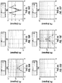
- Figures 4 and 5 are, respectively, plots of compensated phase shift and compensated attenuation responses versus toolface angle for each of the nine couplings.
- Five curves are plotted in each plot, each curve corresponding to a particular anisotropic ratio.
- the horizontal resistivity is two ohm-m.
- the relative formation dip is 60 degrees and the azimuthal dip is zero.
- the phase shift (PS) and attenuation (AD) responses are equal to the anti-symmetrized phase shift (APS) and anti-symmetrized attenuation (AAD) responses, respectively.
- the symmetrized phase shift (SPS) and symmetrized attenuation (SAD) responses are zero.
- Figures 6 and 7 are, respectively, plots of compensated phase shift and compensated attenuation responses versus relative dip angle for each of the nine couplings, wherein the tool x-axis is aligned with the azimuthal dip. Again, five curves are plotted in each plot, each curve corresponding to a particular anisotropic ratio. For each ratio, the horizontal resistivity is two ohm-m.
- Figures 8 and 9 are, respectively, compensated phase shift and compensated attenuation responses versus conductivity for a homogeneous, isotropic formation. The predominantly upper curve in each of those plots is the ZZ response, and the other curve is the XX/YY response.
- resistivity transforms for the direct terms for a particular case have been computed and are shown in Figure 10 .
- the plots are, for each coupling, the phase resistivity of a formation with a 0.9144 m (three foot) bed thickness versus the log depth, for five different anisotropic ratios.
- the signal frequency is 400 kHz and the relative dip is 60 degrees.
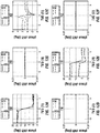
- Figures 12 and 13 show that the compensated phase shift and compensated attenuation respond to both the bed boundary and to the anistropy.
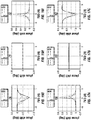
- the symmetrized responses are zero in a homogeneous medium and respond at the bed boundary ( Figure 16 and 17 ).
- the symmetrized XZ response is independent of anisotropy of the beds, is proportional to the difference in conductivity between the beds, and changes sign depending on whether the tool goes from a conductive to a resistive bed or vice versa.
- the XX and ZZ symmetrized responses are also zero in a homogeneous medium and respond at a bed boundary, but in this case it responds to the dip of the bed independent of anisotropy.
- the bed boundary response though present, is reduced compared to the compensated phase shift and compensated attenuation responses.
- FIG. 18 one alternate embodiment is shown in Figure 18 .
- the matrix phase shift and attenuations computed by the gain calibrated combination: V 32 ⁇ 1 V 31 V 22 ⁇ 1 V 21 V 21 ⁇ 1 V 11 would give a response having a depth of investigation comparable to the longer transmitter/receiver spacing.
- the vertical response would be dominated by the Transmitter 3 response and could provide an electromagnetic look-ahead capability.
- Not all possible tensor combinations have been disclosed herein; there are other ways of combining propagation tensors that are within the scope of this disclosure.
- Figure 19 shows a flowchart of an example outside the scope of the present invention that includes providing a logging tool having a plurality of antennas spatially separated along a longitudinal axis of the logging tool (1902); making propagation-style measurements using the plurality of antennas in a formation (1904); forming tensors using the propagation-style measurements (1906); computing one or more quantities using the tensors (1908); and performing a formation evaluation using the one or more computed quantities (1910).
- Figure 20 shows a flowchart of an alternate embodiment in accordance with the present invention that includes calculating borehole compensation matrix products using voltages from the triaxial receiver pairs (2002); applying transverse receiver gain ratio corrections (2004); applying air calibration (2006); calculating symmetrized and anti-symmetrized matrix products (2008); rotating the matrix products (2010); and calculating the phase shift and attenuation responses (2012).
- a zero-dimension inversion meaning an inversion using an infinite, homogeneous, anisotropic, dipping formation model
- drilling using a downhole processor and the measurements, and, for example, the determined horizontal resistivity, vertical resistivity, relative dip, and/or azimuthal dip information may be sent to an uphole processor in real-time.
Landscapes
- Life Sciences & Earth Sciences (AREA)
- Physics & Mathematics (AREA)
- Engineering & Computer Science (AREA)
- Environmental & Geological Engineering (AREA)
- Geology (AREA)
- Remote Sensing (AREA)
- General Life Sciences & Earth Sciences (AREA)
- General Physics & Mathematics (AREA)
- Geophysics (AREA)
- Electromagnetism (AREA)
- Geophysics And Detection Of Objects (AREA)
Description
- Logging tools have long been used in wellbores to make, for example, formation evaluation measurements to infer properties of the formations surrounding the borehole and the fluids in the formations. Common logging tools include electromagnetic tools, nuclear tools, and nuclear magnetic resonance (NMR) tools, though various other tool types are also used.
- Early logging tools were run into a wellbore on a wireline cable, after the wellbore had been drilled. Modern versions of such wireline tools are still used extensively. However, the need for information while drilling the borehole gave rise to measurement-while-drilling (MWD) tools and logging-while-drilling (LWD) tools. By collecting and processing such information during the drilling process, the driller can modify or correct key steps of the operation to optimize performance.
- MWD tools sometimes provide drilling parameter information such as weight on the bit, torque, temperature, pressure, direction, and inclination. LWD tools sometimes provide formation evaluation measurements such as resistivity, porosity, and NMR distributions. MWD and LWD tools often have components common to wireline tools (e.g., transmitting and receiving antennas), but MWD and LWD tools must be constructed to not only endure but to operate in the harsh environment of drilling. The terms MWD and LWD are often used interchangeably, and the use of either term in this disclosure will be understood to include both the collection of formation and wellbore information, as well as data on movement and placement of the drilling assembly.
- Logging tools can also be used to image a wellbore. For example, measurements of resistivity, density, the photoelectric factor, natural gamma ray radiation, the dielectric constant, and acoustic impedance (e.g., ultrasonics) have been used to form wellbore images. Most, if not all, of those imaging methods are dependent on the type of drilling fluid ("mud") used.
-
WO2011/139761 describes a method for obtaining gain-corrected measurements, comprising: providing a measurement tool having one or more arrays, wherein the arrays comprise two co- located triaxial transmitters and two co-located triaxial receivers; obtaining measurements using the two co-located triaxial transmitters and the two co-located triaxial receivers; forming impedance matrices from the obtained measurements; and combining the impedance matrices to provide gain-corrected measurements. -
US 2011/238312 discloses a logging tool carrying out borehole compensated resistivity measurements. - The present invention resides in a method as defined in
claim 1 and in a logging tool as defined inclaim 8. - Embodiments of a borehole imaging and formation evaluation logging-while-drilling tool are described with reference to the following figures. The same numbers are generally used throughout the figures to reference like features and components.
-
Figure 1 illustrates a well site system. -
Figure 2 shows a prior art electromagnetic logging tool. -
Figure 3 schematically shows an embodiment of a propagation tool having a plurality of triaxial antennas, in accordance with the present invention. -
Figure 4 is a plot of the compensated phase shift response versus toolface angle for each of the nine couplings, in accordance with the present disclosure. -
Figure 5 is a plot of the compensated attenuation response versus toolface angle for each of the nine couplings, in accordance with the present disclosure. -
Figure 6 is a plot of the compensated phase shift response versus relative dip angle for each of the nine couplings, in accordance with the present disclosure. -
Figure 7 is a plot of the compensated attenuation response versus relative dip angle for each of the nine couplings, in accordance with the present disclosure. -
Figure 8 is a plot of the compensated phase shift response versus conductivity for a homogeneous, isotropic formation, in accordance with the present disclosure. -
Figure 9 is a plot of the compensated attenuation response versus conductivity for a homogeneous, isotropic formation, in accordance with the present disclosure. -
Figure 10 is a plot, for each coupling, of the phase resistivity of a formation with a 0.9144 m (three foot) bed thickness versus the log depth, for five different anisotropic ratios, in accordance with the present disclosure. -
Figure 11 is a schematic representation of an example layered formation having particular horizontal and vertical resistivities, in accordance with the present disclosure. -
Figure 12 is a plot of the compensated phase shift response versus true vertical depth for each of the nine couplings, in accordance with the present disclosure. -
Figure 13 is a plot of the compensated attenuation response versus true vertical depth for each of the nine couplings, in accordance with the present disclosure. -
Figure 14 is a plot of the anti-symmetrized phase shift response versus true vertical depth for each of the nine couplings, in accordance with the present disclosure. -
Figure 15 is a plot of the anti-symmetrized attenuation response versus true vertical depth for each of the nine couplings, in accordance with the present disclosure. -
Figure 16 is a plot of the symmetrized phase shift response versus true vertical depth for each of the nine couplings, in accordance with the present disclosure. -
Figure 17 is a plot of the symmetrized attenuation response versus true vertical depth for each of the nine couplings, in accordance with the present disclosure. -
Figure 18 schematically shows an alternative embodiment of a propagation tool having a plurality of triaxial antennas, in accordance with the present invention. -
Figure 19 is a flowchart showing an example outside the scope of the present invention. -
Figure 20 shows a flowchart of an embodiment in accordance with the present invention. - It should be understood that the drawings are not to scale and that the disclosed embodiments are sometimes illustrated diagrammatically and in partial views. In certain instances, details that are not necessary for an understanding of the disclosed method and apparatus or that would render other details difficult to perceive may have been omitted. It should be understood that this disclosure is not limited to the particular embodiments illustrated herein.
- Some embodiments will now be described with reference to the figures. Like elements in the various figures may be referenced with like numbers for consistency. In the following description, numerous details are set forth to provide an understanding of various embodiments and/or features. However, it will be understood by those skilled in the art that some embodiments may be practiced without many of these details and that numerous variations or modifications from the described embodiments are possible. As used here, the terms "above" and "below", "up" and "down", "upper" and "lower", "upwardly" and "downwardly", and other like terms indicating relative positions above or below a given point or element are used in this description to more clearly describe certain embodiments. However, when applied to equipment and methods for use in wells that are deviated or horizontal, such terms may refer to a left to right, right to left, or diagonal relationship, as appropriate.
-
Figure 1 illustrates a well site system in which various embodiments can be employed. The well site can be onshore or offshore. In this example system, aborehole 11 is formed in subsurface formations by rotary drilling in a manner that is well known. Some embodiments can also use directional drilling, as will be described hereinafter. - A
drill string 12 is suspended within theborehole 11 and has abottom hole assembly 100 which includes adrill bit 105 at its lower end. The surface system includes platform andderrick assembly 10 positioned over theborehole 11, theassembly 10 including a rotary table 16, kelly 17,hook 18 androtary swivel 19. Thedrill string 12 is rotated by the rotary table 16, energized by means not shown, which engages the kelly 17 at the upper end of the drill string. Thedrill string 12 is suspended from ahook 18, attached to a traveling block (also not shown), through thekelly 17 and arotary swivel 19 which permits rotation of the drill string relative to the hook. As is well known, a top drive system could alternatively be used. - In the example of this embodiment, the surface system further includes drilling fluid or
mud 26 stored in apit 27 formed at the well site. A pump 29 delivers thedrilling fluid 26 to the interior of thedrill string 12 via a port in the swivel 19, causing the drilling fluid to flow downwardly through thedrill string 12 as indicated by thedirectional arrow 8. The drilling fluid exits thedrill string 12 via ports in thedrill bit 105, and then circulates upwardly through the annulus region between the outside of the drill string and the wall of the borehole, as indicated by thedirectional arrows 9. In this well known manner, the drilling fluid lubricates thedrill bit 105 and carries formation cuttings up to the surface as it is returned to thepit 27 for recirculation. - The
bottom hole assembly 100 of the illustrated embodiment includes a logging-while-drilling (LWD)module 120, a measuring-while-drilling (MWD)module 130, a roto-steerable system andmotor 150, anddrill bit 105. - The
LWD module 120 is housed in a special type of drill collar, as is known in the art, and can contain one or a plurality of known types of logging tools. It will also be understood that more than one LWD and/or MWD module can be employed, e.g. as represented at 121. (References, throughout, to a module at the position of 120 can alternatively mean a module at the position of 121 as well.) The LWD module includes capabilities for measuring, processing, and storing information, as well as for communicating with the surface equipment. In the present embodiment, the LWD module includes a resistivity measuring device. - The
MWD module 130 is also housed in a special type of drill collar, as is known in the art, and can contain one or more devices for measuring characteristics of the drill string and drill bit. The MWD tool further includes an apparatus (not shown) for generating electrical power to the downhole system. This may sometimes include a mud turbine generator powered by the flow of the drilling fluid, it being understood that other power and/or battery systems may be employed. In the present embodiment, the MWD module includes one or more of the following types of measuring devices: a weight-on-bit measuring device, a torque measuring device, a vibration measuring device, a shock measuring device, a stick/slip measuring device, a direction measuring device, and an inclination measuring device. - An example of a tool which can be the
LWD tool 120, or can be a part of anLWD tool suite 121, is shown inFigure 2 . As seen inFigure 2 , upper and lower transmitting antennas, T1 and T2 have upper and lower receiving antennas, R1 and R2, therebetween. The antennas are formed in recesses in a modified drill collar and mounted in MC or insulating material. The phase shift of the electromagnetic wave between the receivers provides an indication of formation resistivity at a relatively shallow depth of investigation, and the attenuation of the electromagnetic wave between the receivers provides an indication of formation resistivity at a relatively deep depth of investigation.U.S. Patent No. 4,899,112 can be referred to for further details. In operation, attenuation-representative signals and phase-representative signals are coupled to a processor, an output of which is coupleable to a telemetry circuit. - Some electromagnetic (EM) logging tools use one or more tilted or transverse antennas, with or without axial antennas. Those antennas may be transmitters or receivers. In some embodiments, a tilted antenna can be considered one whose dipole moment is neither parallel nor perpendicular to the longitudinal axis of the tool. A transverse antenna can be considered one whose dipole moment is perpendicular to the longitudinal axis of the tool, and an axial antenna can be considered one whose dipole moment is parallel to the longitudinal axis of the tool. A triaxial antenna can be considered one in which three antennas (i.e., antenna coils) are arranged to be mutually orthogonal. Often one antenna (coil) is axial and the other two are transverse. Two antennas are said to have equal angles if their dipole moment vectors intersect the tool's longitudinal axis at the same angle. For example, two tilted antennas have the same tilt angle if their dipole moment vectors, having their tails conceptually fixed to a point on the tool's longitudinal axis, lie on the surface of a right circular cone centered on the tool's longitudinal axis and having its vertex at that reference point. Transverse antennas have equal angles of 90 degrees, and that is true regardless of their azimuthal orientations relative to the tool.
- It is well known in the art that the resistivity and conductivity of a material are reciprocally related. That is, one is the reciprocal of the other. Thus, the terms "resistivity" and "conductivity" may be used interchangeably herein in the sense that wherever one appears it may be conceptually replaced with the corresponding reciprocal of the other.
- A tool and method to obtain phase shift and attenuation information from propagation-style measurements made using an array of antennas, such as triaxial orthogonal antennas, are described herein. For ease of discussion triaxial antennas are discussed below, but that is not meant to be a limitation and any sort of measurement scheme that provides the full conductivity tensor, with or without tool rotation, may be used. Triaxial propagation measurements contain the formation information in the full conductivity tensor. Better results may be obtained if the antenna coils of a particular transmitter or receiver are co-located. By using the full tensor, borehole compensation may be extended to the triaxial measurements, as opposed to using the term-by-term or element-by-element prior art approach. No a priori assumptions need be made regarding the formation, and no constraints on dip angles or distances to bed boundaries need be made.
- The induced voltage, Vinduced, on a receiver coil is proportional to the current I in a transmitter coil:


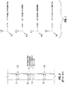
- A propagation tool array such as the embodiment shown in
Figure 3 comprises two triaxial transmitters and two triaxial receivers. Each triaxial antenna comprises three antenna coils that are oriented such that the directions of their magnetic moments (denoted as arrows in the figure) are an orthogonal set. The antennas can be designed to operate at one or more frequencies. Note, the borehole compensation described herein is equally valid for non-orthogonal tilted coils. The voltage measured, for example, on the x-directed coil of Receiver 2 (R2x) induced by the current in the z-directed transmitter coil of Transmitter 1 (T1z) is:


-
Transmitter 1 gains can be eliminated by taking the combination of voltages given by:
Transmitter 2 gains can be eliminated using:


- Note that the zz terms of those matrices are the traditional standard borehole compensated propagation measurement:

- In rotary drilling, the tool normally rotates about its longitudinal axis. In this case, measurements made on one transverse receiver at rotation angles 90 degrees apart is equivalent to making a measurement with separate orthogonal transverse coils. Because one transverse coil is employed per receiver, one gain ratio calibration may be required.
- Once the gain ratios are compensated, the measurements can be rotated to another reference frame. That is, after compensation, U 21 and U 12, can be rotated to a chosen Earth-referenced rotation angle, as each are the product of rotatable tensors:

- Air calibration is used in traditional propagation tools to improve measurement accuracy by subtracting out measurement variability due to the finite size and conductivity of the collar.
- The borehole compensated air calibration values:


- Certain combinations of the U tensors can be formed that give responses similar to what are commonly referred to as the symmetrized and anti-symmetrized measurements. The anti-symmetrized combination is:


- The phase shift and attenuation of the propagation tensors are calculated using the matrix square root (sqrtm) and matrix log (logm) functions:


- In general, because the propagation matrices do not commute, matrix multiplications must often be done in a specific order before calculating the matrix phase shift and attenuation. In addition, the gain components in some embodiments should be removed or compensated prior to rotating a tensor. Basic responses for the triaxial arrays of
Figure 3 operating in a homogeneous medium at 2 MHz with near transmitter-receiver spacings of 83.82 cm (33 inches) and a receiver spacing of 55.88 cm (22 inches) are shown inFigures 4 - 9 . -
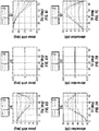
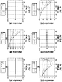
Figures 4 and5 are, respectively, plots of compensated phase shift and compensated attenuation responses versus toolface angle for each of the nine couplings. Five curves are plotted in each plot, each curve corresponding to a particular anisotropic ratio. For each ratio, the horizontal resistivity is two ohm-m. The relative formation dip is 60 degrees and the azimuthal dip is zero. In the homogeneous medium, the phase shift (PS) and attenuation (AD) responses are equal to the anti-symmetrized phase shift (APS) and anti-symmetrized attenuation (AAD) responses, respectively. The symmetrized phase shift (SPS) and symmetrized attenuation (SAD) responses are zero. -
Figures 6 and7 are, respectively, plots of compensated phase shift and compensated attenuation responses versus relative dip angle for each of the nine couplings, wherein the tool x-axis is aligned with the azimuthal dip. Again, five curves are plotted in each plot, each curve corresponding to a particular anisotropic ratio. For each ratio, the horizontal resistivity is two ohm-m.Figures 8 and 9 are, respectively, compensated phase shift and compensated attenuation responses versus conductivity for a homogeneous, isotropic formation. The predominantly upper curve in each of those plots is the ZZ response, and the other curve is the XX/YY response. - As an illustrative example, resistivity transforms for the direct terms for a particular case have been computed and are shown in
Figure 10 . The plots are, for each coupling, the phase resistivity of a formation with a 0.9144 m (three foot) bed thickness versus the log depth, for five different anisotropic ratios. The signal frequency is 400 kHz and the relative dip is 60 degrees. - For the particular set of bed horizontal and vertical resistivities shown in
Figure 11 , where Rh1 is five ohm-m, Rv1 is 10 ohm-m, Rh2 is 20 ohm-m, and Rv2 is 30 ohm-m, the basic responses to the single boundary are shown inFigures 12 - 17 . In all cases the beds have "Tl" anisotropy (meaning the Rh in a plane parallel to the bed is uniform (Rx=Ry=Rh≠Rv=Rz); note this use of Tl has nothing to do with transmitter identification) with a dip azimuth of zero degrees. The tool is oriented such that the toolface angle is zero.Figures 12 and13 show that the compensated phase shift and compensated attenuation respond to both the bed boundary and to the anistropy. The symmetrized responses are zero in a homogeneous medium and respond at the bed boundary (Figure 16 and17 ). At high dip and moderate conductivities, the symmetrized XZ response is independent of anisotropy of the beds, is proportional to the difference in conductivity between the beds, and changes sign depending on whether the tool goes from a conductive to a resistive bed or vice versa. The XX and ZZ symmetrized responses are also zero in a homogeneous medium and respond at a bed boundary, but in this case it responds to the dip of the bed independent of anisotropy. In the anti-symmetrized responses (Figure 14 and15 ), the bed boundary response, though present, is reduced compared to the compensated phase shift and compensated attenuation responses. - The above disclosure considers the arrays formed using two triaxial transmitters and two triaxial receivers. Other triaxial transmitter and receiver combinations could be made to form 'mixed' borehole compensated arrays. This can apply to wireline, LWD, coiled tubing, smart completions, and most any other known or reasonably foreseeable conveyance means.
- For example, one alternate embodiment is shown in
Figure 18 . The matrix phase shift and attenuations computed by the gain calibrated combination:
Transmitter 3 response and could provide an electromagnetic look-ahead capability. Not all possible tensor combinations have been disclosed herein; there are other ways of combining propagation tensors that are within the scope of this disclosure. -
Figure 19 shows a flowchart of an example outside the scope of the present invention that includes providing a logging tool having a plurality of antennas spatially separated along a longitudinal axis of the logging tool (1902); making propagation-style measurements using the plurality of antennas in a formation (1904); forming tensors using the propagation-style measurements (1906); computing one or more quantities using the tensors (1908); and performing a formation evaluation using the one or more computed quantities (1910). -
Figure 20 shows a flowchart of an alternate embodiment in accordance with the present invention that includes calculating borehole compensation matrix products using voltages from the triaxial receiver pairs (2002); applying transverse receiver gain ratio corrections (2004); applying air calibration (2006); calculating symmetrized and anti-symmetrized matrix products (2008); rotating the matrix products (2010); and calculating the phase shift and attenuation responses (2012). - A zero-dimension inversion (meaning an inversion using an infinite, homogeneous, anisotropic, dipping formation model) may be performed, while drilling, using a downhole processor and the measurements, and, for example, the determined horizontal resistivity, vertical resistivity, relative dip, and/or azimuthal dip information may be sent to an uphole processor in real-time.
- While only certain embodiments have been set forth, alternatives and modifications will be apparent from the above description to those skilled in the art. For example, although much of the disclosure above describes propagation-style measurements, induction-style measurements also can be used. Although only a few example embodiments have been described in detail above, those skilled in the art will readily appreciate that many modifications are possible in the example embodiments without materially departing from this invention. Accordingly, all such modifications are intended to be included within the scope of this disclosure as defined in the following claims.
Claims (10)
- A method, comprising:providing (1902) a logging tool (120) including an antenna array comprising a plurality of triaxial antennas (T1, T2, R1, R2) spatially separated along a longitudinal axis of the logging tool (120);making (1904) resistivity measurements in a formation at one or more frequencies using the antenna array;calculating (2002) uncorrected borehole compensation matrix products using voltages from triaxial receiver pairs of the antenna array;applying (2004) transverse receiver gain ratio corrections to the uncorrected borehole compensated matrix products using a gain ratio correction and a gain ratio calibration for calculating gain corrected borehole compensated matrix products;applying (2006) air calibration to the gain corrected borehole compensated matrix products for calculating air calibrated, gain corrected, borehole compensated matrix products;calculating (2008) symmetrized and anti-symmetrized matrix products using the air calibrated, gain corrected, borehole compensated matrix products;rotating (2010) the symmetrized and anti-symmetrized matrix products using a rotation angle;calculating (2012) a matrix phase shift response and a matrix attenuation response using the rotated symmetrized and anti-symmetrized matrix products; anddetermining a formation property or parameter using the matrix phase shift response and/or the matrix attenuation response.
- The method of claim 1, wherein the formation property or parameter is selected from the group consisting of horizontal resistivity, vertical resistivity, relative dip, azimuthal dip, bed boundary location, and bed thickness.
- The method of claim 1, wherein each of triaxial antennas comprises an orthogonal set of antenna coils.
- The method of claim 1, wherein the resistivity measurements include transfer impedances of the antennas.
- The method of claim 1, further comprising performing, while drilling, a zero-dimension inversion using a downhole processor and the measurements, and sending horizontal resistivity, vertical resistivity, relative dip, and/or azimuthal dip information to an uphole processor in real-time.
- The method of claim 1, wherein the computed matrix phase shift response and the computed matrix attenuation response yield a depth of investigation comparable to the length of the longest transmitter/receiver spacing.
- The method of claim 1, wherein the logging tool is conveyed on a wireline, a logging-while-drilling string, a coiled tubing, or a smart completion.
- A logging tool (120), comprising:an antenna array comprising a plurality of triaxial antennas (T1, T2, R1,R2) spatially separated along a longitudinal axis of the logging tool (120); anda downhole processor configured to:make (1904) resistivity measurements in a formation at one or more frequencies using the plurality of antennas;calculate (2002) uncorrected borehole compensation matrix products using voltages from triaxial receiver pairs of the antenna array;apply (2004) transverse receiver gain ratio corrections to the uncorrected borehole compensated matrix products using a gain ratio correction and a gain ratio calibration for calculating gain corrected borehole compensated matrix products;apply (2006) air calibration to the gain corrected borehole compensated matrix products for calculating air calibrated, gain corrected, borehole compensated matrix products;calculate (2008) symmetrized and anti-symmetrized matrix products using the air calibrated, gain corrected, borehole compensated matrix products;rotate (2010) the symmetrized and anti-symmetrized matrix products using a rotation angle;calculate (2012) a matrix phase shift response and a matrix attenuation response using the rotated symmetrized and anti-symmetrized matrix products; anddetermine a formation property or parameter using the matrix phase shift response and/or the matrix attenuation response.
- The logging tool of claim 8, wherein one or more of the antennas is a co-located triaxial antenna.
- The logging tool of claim 9, wherein each of the one or more co-located triaxial antennas comprises an orthogonal set of antenna coils.
Applications Claiming Priority (2)
| Application Number | Priority Date | Filing Date | Title |
|---|---|---|---|
| US13/333,354 US10371852B2 (en) | 2011-12-21 | 2011-12-21 | Formation properties from conductivity tensor |
| PCT/US2012/068906 WO2013095997A1 (en) | 2011-12-21 | 2012-12-11 | Formation properties from conductivity tensor |
Publications (3)
| Publication Number | Publication Date |
|---|---|
| EP2795369A1 EP2795369A1 (en) | 2014-10-29 |
| EP2795369A4 EP2795369A4 (en) | 2015-09-30 |
| EP2795369B1 true EP2795369B1 (en) | 2021-08-11 |
Family
ID=48655387
Family Applications (1)
| Application Number | Title | Priority Date | Filing Date |
|---|---|---|---|
| EP12859535.2A Active EP2795369B1 (en) | 2011-12-21 | 2012-12-11 | Formation properties from conductivity tensor |
Country Status (6)
| Country | Link |
|---|---|
| US (1) | US10371852B2 (en) |
| EP (1) | EP2795369B1 (en) |
| AU (1) | AU2012355647B2 (en) |
| BR (1) | BR112014015707A8 (en) |
| MX (1) | MX353193B (en) |
| WO (1) | WO2013095997A1 (en) |
Families Citing this family (16)
| Publication number | Priority date | Publication date | Assignee | Title |
|---|---|---|---|---|
| US9804292B2 (en) * | 2013-07-25 | 2017-10-31 | Schlumberger Technology Corporation | Term by term gain calibration of triaxial propagation measurements |
| WO2015027010A1 (en) * | 2013-08-21 | 2015-02-26 | Schlumberger Canada Limited | Gain compensated tensor propagation measurements using collocated antennas |
| WO2015072883A1 (en) * | 2013-11-18 | 2015-05-21 | Baker Hughes Incorporated | Methods of transient em data compression |
| WO2015099779A1 (en) * | 2013-12-27 | 2015-07-02 | Halliburton Energy Services, Inc. | Multifrequency processing to determine formation properties |
| US9448324B2 (en) | 2014-03-29 | 2016-09-20 | Schlumberger Technology Corporation | Gain compensated directional propagation measurements |
| US9541666B2 (en) | 2014-03-29 | 2017-01-10 | Schlumberger Technology Corporation | Electromagnetic logging while drilling tool |
| EP3126626A4 (en) | 2014-03-30 | 2017-11-15 | Services Pétroliers Schlumberger | Gain compensated measurements using tilted antennas |
| CN105301658B (en) * | 2014-06-26 | 2018-05-22 | 中石化石油工程地球物理有限公司胜利分公司 | The method that extraction near surface deconvolution operator is recorded using micro logging |
| US9618647B2 (en) * | 2014-10-27 | 2017-04-11 | Schlumberger Technology Corporation | Gain compensated symmetrized and anti-symmetrized angles |
| US9766365B2 (en) * | 2014-10-27 | 2017-09-19 | Schlumberger Technology Corporation | Compensated deep measurements using a tilted antenna |
| GB2556607B (en) * | 2015-09-23 | 2021-12-15 | Schlumberger Technology Bv | Methods of estimating borehole and formation properties using an electromagnetic induction logging tool having random tool decenter positions during data acqu |
| US10743012B2 (en) * | 2016-12-15 | 2020-08-11 | Schlumberger Technology Corporation | Feature compensated borehole image coding |
| CN108049865B (en) * | 2017-09-12 | 2021-08-03 | 中国石油天然气集团公司 | Electric field calibration method for induction logging while drilling |
| CN109057785B (en) * | 2018-07-27 | 2022-06-03 | 中国石油天然气股份有限公司 | Method for evaluating residual geological reserves of compact heterogeneous reservoir |
| WO2021202572A1 (en) | 2020-03-31 | 2021-10-07 | Schlumberger Technology Corporation | Determining formation conductivity with propagation measurements |
| US12060789B2 (en) * | 2022-05-24 | 2024-08-13 | Halliburton Energy Services, Inc. | Scaling factor for calibrating antennas of a wellbore tool |
Citations (1)
| Publication number | Priority date | Publication date | Assignee | Title |
|---|---|---|---|---|
| US20110238312A1 (en) * | 2009-05-04 | 2011-09-29 | Jean Seydoux | Directional resistivity measurement for well placement and formation evaluation |
Family Cites Families (35)
| Publication number | Priority date | Publication date | Assignee | Title |
|---|---|---|---|---|
| US3849721A (en) * | 1973-08-23 | 1974-11-19 | Schlumberger Technology Corp | Microwave logging apparatus having dual processing channels |
| US4899112A (en) | 1987-10-30 | 1990-02-06 | Schlumberger Technology Corporation | Well logging apparatus and method for determining formation resistivity at a shallow and a deep depth |
| US5869968A (en) * | 1994-03-11 | 1999-02-09 | Baker Hughes Incorporated | Method and apparatus for avoiding mutual coupling between receivers in measurement while drilling |
| US6304086B1 (en) | 1999-09-07 | 2001-10-16 | Schlumberger Technology Corporation | Method and apparatus for evaluating the resistivity of formations with high dip angles or high-contrast thin layers |
| US6584408B2 (en) | 2001-06-26 | 2003-06-24 | Schlumberger Technology Corporation | Subsurface formation parameters from tri-axial measurements |
| US6556016B2 (en) | 2001-08-10 | 2003-04-29 | Halliburton Energy Services, Inc. | Induction method for determining dip angle in subterranean earth formations |
| US7463035B2 (en) | 2002-03-04 | 2008-12-09 | Baker Hughes Incorporated | Method and apparatus for the use of multicomponent induction tool for geosteering and formation resistivity data interpretation in horizontal wells |
| US6998844B2 (en) * | 2002-04-19 | 2006-02-14 | Schlumberger Technology Corporation | Propagation based electromagnetic measurement of anisotropy using transverse or tilted magnetic dipoles |
| GB2409526B (en) | 2002-07-10 | 2005-11-30 | Exxonmobil Upstream Res Co | Apparatus and method for measurement of the magnetic induction tensor using triaxial induction arrays |
| US6832159B2 (en) | 2002-07-11 | 2004-12-14 | Schlumberger Technology Corporation | Intelligent diagnosis of environmental influence on well logs with model-based inversion |
| US7414391B2 (en) * | 2002-07-30 | 2008-08-19 | Schlumberger Technology Corporation | Electromagnetic logging tool calibration system |
| US6819111B2 (en) | 2002-11-22 | 2004-11-16 | Baker Hughes Incorporated | Method of determining vertical and horizontal resistivity, and relative dip in anisotropic earth formations having an arbitrary electro-magnetic antenna combination and orientation with additional rotation and position measurements |
| US7382135B2 (en) * | 2003-05-22 | 2008-06-03 | Schlumberger Technology Corporation | Directional electromagnetic wave resistivity apparatus and method |
| US7737697B2 (en) | 2003-12-03 | 2010-06-15 | Baker Hughes Incorporated | Method and apparatus for use of the real component of a magnetic field of multicomponent resistivity measurements |
| US7027923B2 (en) | 2003-12-12 | 2006-04-11 | Schlumberger Technology Corporation | Method for determining sonde error for an induction or propagation tool with transverse or triaxial arrays |
| WO2005083467A1 (en) | 2004-02-23 | 2005-09-09 | Oxford Geoservice Limited | Method and apparatus for gradient electromagnetic induction well logging |
| US7386430B2 (en) | 2004-03-19 | 2008-06-10 | Schlumberger Technology Corporation | Method of correcting triaxial induction arrays for borehole effect |
| US7239145B2 (en) | 2004-03-29 | 2007-07-03 | Schlumberger Technology Center | Subsurface electromagnetic measurements using cross-magnetic dipoles |
| US7848887B2 (en) * | 2004-04-21 | 2010-12-07 | Schlumberger Technology Corporation | Making directional measurements using a rotating and non-rotating drilling apparatus |
| US8112227B2 (en) * | 2004-06-15 | 2012-02-07 | Baker Hughes Incorporated | Processing of multi-component induction measurements in a biaxially anisotropic formation |
| US8060310B2 (en) | 2004-06-15 | 2011-11-15 | Baker Hughes Incorporated | Geosteering in earth formations using multicomponent induction measurements |
| US7392137B2 (en) | 2004-06-15 | 2008-06-24 | Baker Hughes Incorporated | Determination of formation anistrophy, dip and azimuth |
| US7536261B2 (en) | 2005-04-22 | 2009-05-19 | Schlumberger Technology Corporation | Anti-symmetrized electromagnetic measurements |
| US7663372B2 (en) | 2006-09-25 | 2010-02-16 | Baker Hughes Incorporated | Resistivity tools with collocated antennas |
| US8571797B2 (en) * | 2007-05-08 | 2013-10-29 | Schlumberger Technology Corporation | Determining borehole corrected formation on properties |
| US20090143991A1 (en) * | 2007-11-30 | 2009-06-04 | Schlumberger Technology Corporation | Measurements in a fluid-containing earth borehole having a mudcake |
| RU2475780C2 (en) | 2007-11-30 | 2013-02-20 | Эксонмобил Апстрим Рисерч Компани | Method of detecting reservoir and cross bed fracturing using triaxial/multicomponent resistivity anisotropy measurements |
| US7733093B2 (en) * | 2007-12-26 | 2010-06-08 | Schlumberger Technology Corporation | Method of and apparatus for measuring tensor resistivity |
| US7839149B2 (en) | 2008-01-11 | 2010-11-23 | Baker Hughes Incorporated | Multi-component resistivity logging tool with multiple antennas using common antenna grooves |
| US8200437B2 (en) | 2008-09-30 | 2012-06-12 | Schlumberger Technology Corporation | Method for borehole correction, formation dip and azimuth determination and resistivity determination using multiaxial induction measurements |
| US8786287B2 (en) | 2009-03-04 | 2014-07-22 | Baker Hughes Incorporated | Collocated tri-axial induction sensors with segmented horizontal coils |
| US8368403B2 (en) | 2009-05-04 | 2013-02-05 | Schlumberger Technology Corporation | Logging tool having shielded triaxial antennas |
| WO2011091216A2 (en) | 2010-01-22 | 2011-07-28 | Schlumberger Canada Limited | Real-time formation anisotropy and dip evaluation using tri-axial induction measurements |
| CN105204077A (en) | 2010-04-29 | 2015-12-30 | 普拉德研究及开发股份有限公司 | Gain-corrected measurements |
| US9606257B2 (en) * | 2010-09-15 | 2017-03-28 | Schlumberger Technology Corporation | Real-time fracture detection and fracture orientation estimation using tri-axial induction measurements |
-
2011
- 2011-12-21 US US13/333,354 patent/US10371852B2/en active Active
-
2012
- 2012-12-11 BR BR112014015707A patent/BR112014015707A8/en not_active IP Right Cessation
- 2012-12-11 WO PCT/US2012/068906 patent/WO2013095997A1/en not_active Ceased
- 2012-12-11 MX MX2014007774A patent/MX353193B/en active IP Right Grant
- 2012-12-11 AU AU2012355647A patent/AU2012355647B2/en active Active
- 2012-12-11 EP EP12859535.2A patent/EP2795369B1/en active Active
Patent Citations (1)
| Publication number | Priority date | Publication date | Assignee | Title |
|---|---|---|---|---|
| US20110238312A1 (en) * | 2009-05-04 | 2011-09-29 | Jean Seydoux | Directional resistivity measurement for well placement and formation evaluation |
Also Published As
| Publication number | Publication date |
|---|---|
| US20130166213A1 (en) | 2013-06-27 |
| EP2795369A1 (en) | 2014-10-29 |
| WO2013095997A1 (en) | 2013-06-27 |
| BR112014015707A2 (en) | 2017-06-13 |
| US10371852B2 (en) | 2019-08-06 |
| EP2795369A4 (en) | 2015-09-30 |
| BR112014015707A8 (en) | 2017-07-04 |
| AU2012355647B2 (en) | 2015-08-13 |
| MX2014007774A (en) | 2015-04-13 |
| AU2012355647A1 (en) | 2014-07-17 |
| MX353193B (en) | 2018-01-05 |
Similar Documents
| Publication | Publication Date | Title |
|---|---|---|
| US10371852B2 (en) | Formation properties from conductivity tensor | |
| US9435909B2 (en) | Imaging using directional resistivity measurements | |
| US8736270B2 (en) | Look ahead logging system | |
| US10768336B2 (en) | Formation logging using multicomponent signal-based measurement of anisotropic permittivity and resistivity | |
| US7755361B2 (en) | Apparatus and system for well placement and reservoir characterization | |
| US10371781B2 (en) | Gain-corrected measurements | |
| US8237445B2 (en) | Octupole induction sensors for resistivity imaging in non-conductive muds | |
| US8558548B2 (en) | Determining anisotropic resistivity | |
| US8417455B2 (en) | Triaxial antenna electromagnetic measurements | |
| GB2486076A (en) | Determining the presence and location of resistivity contrasts ahead of a well drilling system | |
| US9835753B2 (en) | Gain compensated tensor propagation measurements using collocated antennas | |
| US10295698B2 (en) | Multi-component induction logging systems and methods using selected frequency inversion | |
| US20110291855A1 (en) | Logging tool with antennas having equal tilt angles | |
| US10365395B2 (en) | Multi-component induction logging systems and methods using blended-model inversion | |
| EP2402792B1 (en) | Determining anisotropic resistivity in a subsurface formation |
Legal Events
| Date | Code | Title | Description |
|---|---|---|---|
| PUAI | Public reference made under article 153(3) epc to a published international application that has entered the european phase |
Free format text: ORIGINAL CODE: 0009012 |
|
| 17P | Request for examination filed |
Effective date: 20140708 |
|
| AK | Designated contracting states |
Kind code of ref document: A1 Designated state(s): AL AT BE BG CH CY CZ DE DK EE ES FI FR GB GR HR HU IE IS IT LI LT LU LV MC MK MT NL NO PL PT RO RS SE SI SK SM TR |
|
| DAX | Request for extension of the european patent (deleted) | ||
| RA4 | Supplementary search report drawn up and despatched (corrected) |
Effective date: 20150902 |
|
| RIC1 | Information provided on ipc code assigned before grant |
Ipc: G01V 3/18 20060101AFI20150827BHEP Ipc: E21B 47/12 20120101ALI20150827BHEP |
|
| 17Q | First examination report despatched |
Effective date: 20150914 |
|
| STAA | Information on the status of an ep patent application or granted ep patent |
Free format text: STATUS: EXAMINATION IS IN PROGRESS |
|
| REG | Reference to a national code |
Ref country code: DE Ref legal event code: R079 Ref document number: 602012076412 Country of ref document: DE Free format text: PREVIOUS MAIN CLASS: G01V0003180000 Ipc: G01V0003300000 |
|
| GRAJ | Information related to disapproval of communication of intention to grant by the applicant or resumption of examination proceedings by the epo deleted |
Free format text: ORIGINAL CODE: EPIDOSDIGR1 |
|
| STAA | Information on the status of an ep patent application or granted ep patent |
Free format text: STATUS: GRANT OF PATENT IS INTENDED |
|
| GRAP | Despatch of communication of intention to grant a patent |
Free format text: ORIGINAL CODE: EPIDOSNIGR1 |
|
| RIC1 | Information provided on ipc code assigned before grant |
Ipc: G01V 3/30 20060101AFI20210205BHEP |
|
| INTG | Intention to grant announced |
Effective date: 20210224 |
|
| GRAS | Grant fee paid |
Free format text: ORIGINAL CODE: EPIDOSNIGR3 |
|
| GRAA | (expected) grant |
Free format text: ORIGINAL CODE: 0009210 |
|
| STAA | Information on the status of an ep patent application or granted ep patent |
Free format text: STATUS: THE PATENT HAS BEEN GRANTED |
|
| AK | Designated contracting states |
Kind code of ref document: B1 Designated state(s): AL AT BE BG CH CY CZ DE DK EE ES FI FR GB GR HR HU IE IS IT LI LT LU LV MC MK MT NL NO PL PT RO RS SE SI SK SM TR |
|
| REG | Reference to a national code |
Ref country code: GB Ref legal event code: FG4D |
|
| REG | Reference to a national code |
Ref country code: CH Ref legal event code: EP |
|
| REG | Reference to a national code |
Ref country code: DE Ref legal event code: R096 Ref document number: 602012076412 Country of ref document: DE |
|
| REG | Reference to a national code |
Ref country code: IE Ref legal event code: FG4D Ref country code: AT Ref legal event code: REF Ref document number: 1419954 Country of ref document: AT Kind code of ref document: T Effective date: 20210915 |
|
| REG | Reference to a national code |
Ref country code: LT Ref legal event code: MG9D |
|
| REG | Reference to a national code |
Ref country code: NL Ref legal event code: MP Effective date: 20210811 |
|
| REG | Reference to a national code |
Ref country code: AT Ref legal event code: MK05 Ref document number: 1419954 Country of ref document: AT Kind code of ref document: T Effective date: 20210811 |
|
| PG25 | Lapsed in a contracting state [announced via postgrant information from national office to epo] |
Ref country code: HR Free format text: LAPSE BECAUSE OF FAILURE TO SUBMIT A TRANSLATION OF THE DESCRIPTION OR TO PAY THE FEE WITHIN THE PRESCRIBED TIME-LIMIT Effective date: 20210811 Ref country code: SE Free format text: LAPSE BECAUSE OF FAILURE TO SUBMIT A TRANSLATION OF THE DESCRIPTION OR TO PAY THE FEE WITHIN THE PRESCRIBED TIME-LIMIT Effective date: 20210811 Ref country code: BG Free format text: LAPSE BECAUSE OF FAILURE TO SUBMIT A TRANSLATION OF THE DESCRIPTION OR TO PAY THE FEE WITHIN THE PRESCRIBED TIME-LIMIT Effective date: 20211111 Ref country code: AT Free format text: LAPSE BECAUSE OF FAILURE TO SUBMIT A TRANSLATION OF THE DESCRIPTION OR TO PAY THE FEE WITHIN THE PRESCRIBED TIME-LIMIT Effective date: 20210811 Ref country code: LT Free format text: LAPSE BECAUSE OF FAILURE TO SUBMIT A TRANSLATION OF THE DESCRIPTION OR TO PAY THE FEE WITHIN THE PRESCRIBED TIME-LIMIT Effective date: 20210811 Ref country code: PT Free format text: LAPSE BECAUSE OF FAILURE TO SUBMIT A TRANSLATION OF THE DESCRIPTION OR TO PAY THE FEE WITHIN THE PRESCRIBED TIME-LIMIT Effective date: 20211213 Ref country code: RS Free format text: LAPSE BECAUSE OF FAILURE TO SUBMIT A TRANSLATION OF THE DESCRIPTION OR TO PAY THE FEE WITHIN THE PRESCRIBED TIME-LIMIT Effective date: 20210811 Ref country code: FI Free format text: LAPSE BECAUSE OF FAILURE TO SUBMIT A TRANSLATION OF THE DESCRIPTION OR TO PAY THE FEE WITHIN THE PRESCRIBED TIME-LIMIT Effective date: 20210811 Ref country code: ES Free format text: LAPSE BECAUSE OF FAILURE TO SUBMIT A TRANSLATION OF THE DESCRIPTION OR TO PAY THE FEE WITHIN THE PRESCRIBED TIME-LIMIT Effective date: 20210811 |
|
| REG | Reference to a national code |
Ref country code: NO Ref legal event code: T2 Effective date: 20210811 |
|
| PG25 | Lapsed in a contracting state [announced via postgrant information from national office to epo] |
Ref country code: PL Free format text: LAPSE BECAUSE OF FAILURE TO SUBMIT A TRANSLATION OF THE DESCRIPTION OR TO PAY THE FEE WITHIN THE PRESCRIBED TIME-LIMIT Effective date: 20210811 Ref country code: LV Free format text: LAPSE BECAUSE OF FAILURE TO SUBMIT A TRANSLATION OF THE DESCRIPTION OR TO PAY THE FEE WITHIN THE PRESCRIBED TIME-LIMIT Effective date: 20210811 Ref country code: GR Free format text: LAPSE BECAUSE OF FAILURE TO SUBMIT A TRANSLATION OF THE DESCRIPTION OR TO PAY THE FEE WITHIN THE PRESCRIBED TIME-LIMIT Effective date: 20211112 |
|
| PG25 | Lapsed in a contracting state [announced via postgrant information from national office to epo] |
Ref country code: NL Free format text: LAPSE BECAUSE OF FAILURE TO SUBMIT A TRANSLATION OF THE DESCRIPTION OR TO PAY THE FEE WITHIN THE PRESCRIBED TIME-LIMIT Effective date: 20210811 |
|
| PG25 | Lapsed in a contracting state [announced via postgrant information from national office to epo] |
Ref country code: DK Free format text: LAPSE BECAUSE OF FAILURE TO SUBMIT A TRANSLATION OF THE DESCRIPTION OR TO PAY THE FEE WITHIN THE PRESCRIBED TIME-LIMIT Effective date: 20210811 |
|
| REG | Reference to a national code |
Ref country code: DE Ref legal event code: R097 Ref document number: 602012076412 Country of ref document: DE |
|
| PG25 | Lapsed in a contracting state [announced via postgrant information from national office to epo] |
Ref country code: SM Free format text: LAPSE BECAUSE OF FAILURE TO SUBMIT A TRANSLATION OF THE DESCRIPTION OR TO PAY THE FEE WITHIN THE PRESCRIBED TIME-LIMIT Effective date: 20210811 Ref country code: SK Free format text: LAPSE BECAUSE OF FAILURE TO SUBMIT A TRANSLATION OF THE DESCRIPTION OR TO PAY THE FEE WITHIN THE PRESCRIBED TIME-LIMIT Effective date: 20210811 Ref country code: RO Free format text: LAPSE BECAUSE OF FAILURE TO SUBMIT A TRANSLATION OF THE DESCRIPTION OR TO PAY THE FEE WITHIN THE PRESCRIBED TIME-LIMIT Effective date: 20210811 Ref country code: EE Free format text: LAPSE BECAUSE OF FAILURE TO SUBMIT A TRANSLATION OF THE DESCRIPTION OR TO PAY THE FEE WITHIN THE PRESCRIBED TIME-LIMIT Effective date: 20210811 Ref country code: CZ Free format text: LAPSE BECAUSE OF FAILURE TO SUBMIT A TRANSLATION OF THE DESCRIPTION OR TO PAY THE FEE WITHIN THE PRESCRIBED TIME-LIMIT Effective date: 20210811 Ref country code: AL Free format text: LAPSE BECAUSE OF FAILURE TO SUBMIT A TRANSLATION OF THE DESCRIPTION OR TO PAY THE FEE WITHIN THE PRESCRIBED TIME-LIMIT Effective date: 20210811 |
|
| PLBE | No opposition filed within time limit |
Free format text: ORIGINAL CODE: 0009261 |
|
| STAA | Information on the status of an ep patent application or granted ep patent |
Free format text: STATUS: NO OPPOSITION FILED WITHIN TIME LIMIT |
|
| REG | Reference to a national code |
Ref country code: DE Ref legal event code: R119 Ref document number: 602012076412 Country of ref document: DE |
|
| 26N | No opposition filed |
Effective date: 20220512 |
|
| PG25 | Lapsed in a contracting state [announced via postgrant information from national office to epo] |
Ref country code: MC Free format text: LAPSE BECAUSE OF FAILURE TO SUBMIT A TRANSLATION OF THE DESCRIPTION OR TO PAY THE FEE WITHIN THE PRESCRIBED TIME-LIMIT Effective date: 20210811 Ref country code: IT Free format text: LAPSE BECAUSE OF FAILURE TO SUBMIT A TRANSLATION OF THE DESCRIPTION OR TO PAY THE FEE WITHIN THE PRESCRIBED TIME-LIMIT Effective date: 20210811 |
|
| REG | Reference to a national code |
Ref country code: CH Ref legal event code: PL |
|
| PG25 | Lapsed in a contracting state [announced via postgrant information from national office to epo] |
Ref country code: SI Free format text: LAPSE BECAUSE OF FAILURE TO SUBMIT A TRANSLATION OF THE DESCRIPTION OR TO PAY THE FEE WITHIN THE PRESCRIBED TIME-LIMIT Effective date: 20210811 |
|
| REG | Reference to a national code |
Ref country code: BE Ref legal event code: MM Effective date: 20211231 |
|
| PG25 | Lapsed in a contracting state [announced via postgrant information from national office to epo] |
Ref country code: LU Free format text: LAPSE BECAUSE OF NON-PAYMENT OF DUE FEES Effective date: 20211211 Ref country code: IE Free format text: LAPSE BECAUSE OF NON-PAYMENT OF DUE FEES Effective date: 20211211 Ref country code: DE Free format text: LAPSE BECAUSE OF NON-PAYMENT OF DUE FEES Effective date: 20220701 |
|
| PG25 | Lapsed in a contracting state [announced via postgrant information from national office to epo] |
Ref country code: FR Free format text: LAPSE BECAUSE OF NON-PAYMENT OF DUE FEES Effective date: 20211231 Ref country code: BE Free format text: LAPSE BECAUSE OF NON-PAYMENT OF DUE FEES Effective date: 20211231 |
|
| PG25 | Lapsed in a contracting state [announced via postgrant information from national office to epo] |
Ref country code: LI Free format text: LAPSE BECAUSE OF NON-PAYMENT OF DUE FEES Effective date: 20211231 Ref country code: CH Free format text: LAPSE BECAUSE OF NON-PAYMENT OF DUE FEES Effective date: 20211231 |
|
| PG25 | Lapsed in a contracting state [announced via postgrant information from national office to epo] |
Ref country code: HU Free format text: LAPSE BECAUSE OF FAILURE TO SUBMIT A TRANSLATION OF THE DESCRIPTION OR TO PAY THE FEE WITHIN THE PRESCRIBED TIME-LIMIT; INVALID AB INITIO Effective date: 20121211 Ref country code: CY Free format text: LAPSE BECAUSE OF FAILURE TO SUBMIT A TRANSLATION OF THE DESCRIPTION OR TO PAY THE FEE WITHIN THE PRESCRIBED TIME-LIMIT Effective date: 20210811 |
|
| PG25 | Lapsed in a contracting state [announced via postgrant information from national office to epo] |
Ref country code: MK Free format text: LAPSE BECAUSE OF FAILURE TO SUBMIT A TRANSLATION OF THE DESCRIPTION OR TO PAY THE FEE WITHIN THE PRESCRIBED TIME-LIMIT Effective date: 20210811 |
|
| PG25 | Lapsed in a contracting state [announced via postgrant information from national office to epo] |
Ref country code: TR Free format text: LAPSE BECAUSE OF FAILURE TO SUBMIT A TRANSLATION OF THE DESCRIPTION OR TO PAY THE FEE WITHIN THE PRESCRIBED TIME-LIMIT Effective date: 20210811 |
|
| PG25 | Lapsed in a contracting state [announced via postgrant information from national office to epo] |
Ref country code: MT Free format text: LAPSE BECAUSE OF FAILURE TO SUBMIT A TRANSLATION OF THE DESCRIPTION OR TO PAY THE FEE WITHIN THE PRESCRIBED TIME-LIMIT Effective date: 20210811 |
|
| PGFP | Annual fee paid to national office [announced via postgrant information from national office to epo] |
Ref country code: GB Payment date: 20251001 Year of fee payment: 14 |
|
| PGFP | Annual fee paid to national office [announced via postgrant information from national office to epo] |
Ref country code: NO Payment date: 20251210 Year of fee payment: 14 |