EP2795286B1 - System for mechanical stimulation and characterization of biologic samples - Google Patents
System for mechanical stimulation and characterization of biologic samples Download PDFInfo
- Publication number
- EP2795286B1 EP2795286B1 EP12798104.1A EP12798104A EP2795286B1 EP 2795286 B1 EP2795286 B1 EP 2795286B1 EP 12798104 A EP12798104 A EP 12798104A EP 2795286 B1 EP2795286 B1 EP 2795286B1
- Authority
- EP
- European Patent Office
- Prior art keywords
- biologic sample
- actuator
- chamber
- biologic
- load
- Prior art date
- Legal status (The legal status is an assumption and is not a legal conclusion. Google has not performed a legal analysis and makes no representation as to the accuracy of the status listed.)
- Active
Links
Images




Classifications
-
- G—PHYSICS
- G01—MEASURING; TESTING
- G01N—INVESTIGATING OR ANALYSING MATERIALS BY DETERMINING THEIR CHEMICAL OR PHYSICAL PROPERTIES
- G01N3/00—Investigating strength properties of solid materials by application of mechanical stress
- G01N3/32—Investigating strength properties of solid materials by application of mechanical stress by applying repeated or pulsating forces
-
- C—CHEMISTRY; METALLURGY
- C12—BIOCHEMISTRY; BEER; SPIRITS; WINE; VINEGAR; MICROBIOLOGY; ENZYMOLOGY; MUTATION OR GENETIC ENGINEERING
- C12M—APPARATUS FOR ENZYMOLOGY OR MICROBIOLOGY; APPARATUS FOR CULTURING MICROORGANISMS FOR PRODUCING BIOMASS, FOR GROWING CELLS OR FOR OBTAINING FERMENTATION OR METABOLIC PRODUCTS, i.e. BIOREACTORS OR FERMENTERS
- C12M35/00—Means for application of stress for stimulating the growth of microorganisms or the generation of fermentation or metabolic products; Means for electroporation or cell fusion
- C12M35/04—Mechanical means, e.g. sonic waves, stretching forces, pressure or shear stimuli
-
- G—PHYSICS
- G01—MEASURING; TESTING
- G01N—INVESTIGATING OR ANALYSING MATERIALS BY DETERMINING THEIR CHEMICAL OR PHYSICAL PROPERTIES
- G01N2203/00—Investigating strength properties of solid materials by application of mechanical stress
- G01N2203/0058—Kind of property studied
- G01N2203/0089—Biorheological properties
-
- G—PHYSICS
- G01—MEASURING; TESTING
- G01N—INVESTIGATING OR ANALYSING MATERIALS BY DETERMINING THEIR CHEMICAL OR PHYSICAL PROPERTIES
- G01N2203/00—Investigating strength properties of solid materials by application of mechanical stress
- G01N2203/02—Details not specific for a particular testing method
- G01N2203/022—Environment of the test
- G01N2203/0236—Other environments
- G01N2203/0242—With circulation of a fluid
-
- G—PHYSICS
- G01—MEASURING; TESTING
- G01N—INVESTIGATING OR ANALYSING MATERIALS BY DETERMINING THEIR CHEMICAL OR PHYSICAL PROPERTIES
- G01N2203/00—Investigating strength properties of solid materials by application of mechanical stress
- G01N2203/02—Details not specific for a particular testing method
- G01N2203/026—Specifications of the specimen
- G01N2203/0262—Shape of the specimen
- G01N2203/0274—Tubular or ring-shaped specimens
Definitions
- This disclosure relates to a system for applying a load to one or more biologic samples.
- Boologic samples may be living or dead tissue or biomaterials, such as biological, synthetic or manufactured biomaterials, medical devices, biosensors or combinations thereof.
- U.S. Patent 7,694,593 discloses a multi-biologic sample conditioning system in which an actuator drives a push-bar assembly 120.
- the push-bar assembly 120 couples an axial displacement of the push-bar assembly to a biologic sample grip inside each biologic sample chamber 105.
- the lower biologic sample grip 250 mechanically transmits a user-defined conditioning profile generated by the actuator to a biologic sample held in the grips 250, 255.
- biologic samples including a biologic material When biologic samples including a biologic material are conditioned, they may be conditioned for a period of time (e.g. 10 minutes) followed by a rest period of time (e.g. 50 minutes). During this rest time the actuator shown in the '593 patent is not being utilized resulting in inefficiency in the system. In addition, only a single actuator is used in the system disclosed in the '593 patent and all biologic samples must undergo exactly the same loading timing regardless of differences in properties. As such, the type and timing of conditioning that the biologic samples can receive are limited by the particular type and timing of the actuator used in the system. US2009/0282927 , US2007/0169572 and US2005/0153436 are also showing systems for applying mechanical stimulation to biological samples.
- a system for applying mechanical stimulation to a biologic sample is defined in claim 1.
- Other aspects are defined in the dependent claims.
- Biologic research and development may require the growth and/or testing of a large number of biologic samples over time.
- Such biologic research and development often involve mechanical stimulation of the individual biologic samples. And such mechanical stimulation is often not continuous nor the same for all biologic samples.
- a researcher may choose to stimulate and/or characterize one biologic sample at a first force and frequency for a first time period (e.g., a fixed time period or until some biologic sample condition is achieved) and stimulate and/or characterize a second biologic sample at a different force and frequency for a different time period (e.g., a different fixed time period or until some other biologic sample condition is achieved).
- Electromagnetic actuators provide clean, precise, and repeatable mechanical stimulation to such biologic samples, but such actuators are often an expensive component to a biologic system.
- Some systems such as the Multi-Chamber ElectroForce® BioDynamic® test instrument from Bose Corporation, provide multi-specimen mechanical stimulation using a shared motor. This type of system, however, cannot easily be scaled to a larger scale system capable of stimulating and characterizing a significantly greater number of biologic samples. Moreover, such a system lacks the ability to individually stimulate the specimens (at least with respect to mechanical stimulation).
- a system that provides the ability to use a number of motors that is less than the number of samples to individually stimulate multiple biologic samples allows a researcher to "time-shift" individual biologic sample stimulation periods so that the motor(s) (an expensive system component) may be better utilized than a motor on a system having individual motors for each biologic sample.
- Such a system allows for the customization of the mechanical stimulation profile since a motor(s) is dedicated to a biologic sample but only for a prescribed period of time.
- Such a system also provides a researcher more flexibility in specifying mechanical stimulation periods for individual biologic samples than systems that use a single motor (or set of motors) to stimulate multiple biologic samples simultaneously (such as the Multi-Chamber ElectroForce® BioDynamic® test instrument mentioned above).
- FIG. 8 shows an example of a biologic testing system that provides increased motor utilization while providing flexibility in mechanical stimulation profiles of biologic samples.
- a single motor system 367 is moved by a controller between sixteen biologic sample chambers (e.g. 105A and 105B).
- the controller preferably includes a user interface that permits a researcher (or other user) to specify various parameters of the mechanical stimulation to create a stimulation profile for each biologic sample.
- the stimulation parameters may include the duration of stimulation (e.g., fixed time period or variable based on achievement of a measured condition), the type of stimulation (tension, compression, torsion, bend, radial, shear, fluid flow, pressure, electrical, magnetic etc), the frequency and magnitude of stimulation, and any other relevant stimulation parameters.
- the simulation profile for each biologic sample may be identical or different in one or more parameters.
- Moving one or a small number of actuators to the chamber(s) is preferred over moving the chamber(s) to the actuator(s), particularly where a large number of chambers or a various or changing combination of actuator types is involved. This is because each chamber will often have tubes connected to it for supplying a fluid to the chamber and removing fluid from the chamber. These tubes can become tangled or snagged as the chambers are moved. Having to move a large number of chambers with their associated tubing would be much more complicated than moving one or a few actuators. Moving the chambers might also be detrimental to the samples contained in the chambers or affect their properties in a non-desirable and/or unknown way.
- Moving the chambers results in the biologic samples being subject to mechanical stimulation due to the movement that depending on the frequency and magnitude could negatively affect biologic sample properties and/or become an unknown stimulation parameter.
- Fixed actuators with movable chambers are less flexible for adapting the cadence and type of loading. For example, with turret style chamber movement, the cadence and sequence of sample stimulation is more rigidly constrained.
- the chambers could be fixed with a dedicated actuator or actuators for each sample chamber. Such an arrangement, however, would be inefficient and expensive.
- FIG. 1 illustrates a front view of a portion of a biologic sample chamber 105.
- the biologic sample chamber is manually prepared in a clean environment by an operator using a dedicated set-up fixture (not shown).
- the biologic sample chamber 105 includes a chamber housing 210 that encloses a chamber volume 205.
- the chamber housing 210 may include a transparent or translucent chamber window 220 allowing automated visual monitoring and measurement of a biologic sample 201.
- the biologic sample chamber may be configured to accommodate a variety of biologic sample grips (i.e. biologic sample holders) according to the type of biologic sample. Grips can be custom-made for a particular type of biologic sample. For example, pincher-type grips may be used to hold a strip such as a ligament, tendon, or skin biologic sample.
- Porous or non-porous platens may be used to hold disk-shaped biologic samples such as cartilage or bone.
- Three- or four-point bend fixtures may be used to condition biologic samples in the chamber such as bone.
- an upper biologic sample grip 240 and a lower biologic sample grip 250 are configured to hold a tubular biologic sample 201 such as a vessel with or without a valve, urethra, bladder or trachea.
- the tubular biologic sample grips each have an end fitting 255 such as, for example, a nozzle or barb fitting that holds an end of the tubular biologic sample.
- the lower biologic sample grip 250 is mechanically coupled to a shaft 260 that extends from the chamber housing 210 such that a free end of the shaft 260 is external to the chamber 105.
- the shaft 260 is connected to a feature 262 that engages with an actuator (described below) that is used to apply a load in one or more axes (e.g. stress, strain, bend) to a biologic sample in the chamber.
- the lower biologic sample grip 250 and chamber housing (210) are connected by a flexible fluid seal that allows for unconstrained motion of the shaft relative to the fixed chamber.
- the grip 250 mechanically transmits a user-defined conditioning profile (i.e. load) generated by the actuator to the held biologic sample.
- the upper biologic sample grip 240 may be set to a fixed position by the operator relative to the chamber housing 210, or in some cases may also utilize a seal to transmit motion or force to actuator(s) or sensor(s).
- a operator When initially setting up the chamber 105, a operator removes the window 220 to secure the biologic sample 201 to the biologic sample grips 240, 250. The operator then manually turns a thumb screw 261 (see also Fig. 6 ) to lock the lower biologic sample grip in place.
- a non-damaging thumb screw is preferably used (e.g. brass dog point, soft flat point, etc). Alternatively, a manually activated shaft clamp collar could be used.
- the window 220 is then secured to the chamber 105 to hermetically seal the chamber.
- a first end of a conduit 264 e.g. tube
- a quick connect fitting 266 is connected to an opening in a left side of the chamber housing 210 by a quick connect fitting 266.
- Conduit 264 can be used to supply a fluid that may contain a nutrient to the external surfaces of the biologic sample in the chamber 105.
- a first end of a conduit 268 (e.g. tube) is connected to an opening in a right side of the chamber housing 210 by a quick connect fitting 272.
- Conduit 268 may be used to exhaust a fluid from the chamber 105.
- Quick connect fittings 274 and 276 are located at respective second ends of the conduits 264 and 268.
- the chamber 105 will only be about half filled with fluid due to the locations of the fittings 266 and 272.
- another pair of fittings (not shown) located at or near a top of the chamber can be used if it is desired to have the chamber 105 completely filled with fluid.
- the biologic sample grips 240, 250 may be hollow to allow additional nutrient flow through the grips and biologic sample during the conditioning protocol. This is enabled by chamber ports 270, 275 which provide fluid communication between the grips 240, 250, the biologic sample 201, and an external nutrient fluid circuit (not shown).
- the details of the nutrient fluid management system and control along with the instrumentation and system controls that may be used is described in U.S. Patent 7,587,949 , herein incorporated by reference in its entirety.
- the chamber 105 with the conduits 264 and 268 is then carried by the operator to a support structure 278 which can removably hold the biologic sample chamber 105.
- the structure 278 may be contained within an incubator which can hold a large number of chambers and provide a controlled environment (e.g. temperature, humidity, gas environment) to the biologic samples.
- the operator aligns four mounting features (e.g. blind holes (not shown)) on the back of the chamber 105 with four alignment pins 280 on the support structure 278 and presses the chamber 105 onto the support structure 278.
- the shaft 260 is inserted through a bore 281 in a radial clamping device such as a lock/unlock gear 283 that is part of the support structure 278.
- a set of latches 282 is used to secure the chamber 105 to the structure 278.
- Fig. 3 shows the chamber 105 mounted to the support structure 278 with the latches 282 in a closed position.
- the operator then connects fittings 274 and 276 (and thus the ends of the conduits 264 and 268) to respective common conduit structures 284 and 286.
- Fluid is supplied to the chamber 105 from the structure 284.
- the structure 284 includes a fluid supply container 287, a filter 288, and a pump 290 (e.g. a peristaltic or gear pump).
- a pump 290 e.g. a peristaltic or gear pump.
- an additional seven conduits can be connected to the structure 284.
- This arrangement allows up to eight biologic sample chambers to be supplied with fluid from a single supply container 287, filter 288 and pump 290.
- the common conduit structures 284 and 286 help to keep the conduits 264, 268 etc. organized when a large number of biologic sample chambers are being used at the same time.
- fluid is transferred from the chamber 105 through the conduit 268 into the structure 286. Fluid from up to an additional seven chambers can be transferred into the structure 286.
- the structure 286 is mostly made up of a fluid container 292.
- the structure 286 is eliminated and the fitting 276 is connected to the container 287. This results in a closed loop fluid circulation system.
- the dynamic pressure and/or flow of the fluid can be controlled to apply additional loads continuously or periodically on the biologic sample 201 in the chamber 105.
- the operator next manually rotates the gear 283 in the direction of an arrow 294 (counterclockwise).
- This rotation causes relative motion (represented by arrows 296) between the gear 283 and a stationary hub 298 which is fixed to the structure 278.
- the relative motion causes a cam surface 300 to push a pair of griping elements 302 and 304 in the respective directions shown by arrows 306 and 308.
- the elements 302 and 304 are thereby forced into pressurized contact with the shaft 260 of the chamber 105, thus holding the shaft 260 in a fixed position.
- the operator rotates the thumb screw 261 (see Fig. 6 ) to release the shaft 260 from the grip of the thumb screw 261.
- the previous steps can be repeated for as many biologic samples and biologic sample chambers as are desired in the stimulation regime.
- a large number of chambers can be placed into an incubator in which one or more actuators will stimulate the biologic samples.
- the incubator is closed up and the biologic sample stimulation regimen is commenced. More biologic samples can be added to or removed from the structure during the stimulation regime without affecting the existing or remaining biologic samples.
- the system now automatically positions an actuator stage 310 underneath the structure 278 using a machine positioning device 311 (e.g. a multiple axes machine vision system) which aligns on a feature 313 on the bottom of the support structure 278.
- the stage 310 is then automatically moved in a direction 312 to cause a driveshaft 314 to engage into the bottom of the shaft 260.
- This movement also causes a driveshaft 316 to be engaged into the bottom of a radial driving device such as a drive gear 318.
- stimulation actuators 342 and 344 are automatically moved into a position proximate to the chamber 105 in which these actuators can transmit a load to the biologic sample 201 via a transmission path that includes the shaft 260 and the biologic sample holder 250.
- an internal pin 320 is moved in the direction 322, for example, by an electric solenoid. This movement causes the pin 320 to press against a lock component 324.
- a lock component 324 There are multiple radially spaced components 324, but only one is shown in Fig. 7 .
- the pressure from the pin 320 against the components 324 presses the components 324 into rigid compression with an internal surface 326 of the shaft 260 to create a rigid joint.
- the frictional resistance supplied by the components 324 against the surface 326 temporarily locks the drive shaft 314 to the shaft 260.
- the driveshaft 314 can transfer load, displacement, torque and/or rotation to the shaft 260 with high rigidity. This same arrangement is used to temporarily lock the driveshaft 316 to the bottom of the drive gear 318 (see Fig. 6 ).
- a microcontroller 332 controls operation of all of the actuators (described below) and measurement of sensors in the motor assemblies on the stage 310.
- Cabling 334 supplies electrical power to the actuator stage 310 and control signals from a main controller (not shown) to the microcontroller 332.
- the microcontroller 332 causes the rotary engagement actuator 338 to operate to turn driveshaft 316 which turns drive gear 318.
- Gear 283 is turned in a clockwise direction (as viewed in Fig. 4 ) which releases the pressure on grips 302/304 and unlocks the shaft 260 from the grips 302/304. Movement of the shaft 260 is now controlled by the drive shaft 314 and the stimulation actuators 342 and 344.
- One or more measurement devices can be used to obtain characteristics of the sample. These devices can travel with the actuator stage (or a separate measurement stage) and/or remain with the sample or chamber even when the actuator stage is moved away from the chamber.
- the load on the sample can be measured by monitoring electrical current in motor 342 or by a load cell in the force transmission path to the sample.
- a measurement device 333 e.g. a laser micrometer or CCD camera
- the device 333 is used to measure a characteristic (e.g. dimension) of the biologic sample 201 at any time while the stage 310 is in the position shown in Fig. 6 .
- Other types of sensors include those to measure, for example, temperature, torque, rotation, strain, electrical properties, magnetic field, and chemical composition.
- the previous steps outline the engagement of the stimulation actuators 342 and 344 to the biologic sample 201. Now that the actuators 342 and 344 are engaged to the biologic sample, and the associated sensors are in place, the stimulation step can occur.
- the microcontroller 332 now operates the linear actuator 342 and/or the rotary actuator 344 to move the driveshaft 314 which in turn moves the shaft 260.
- the linear actuator 342 e.g. a linear electro-magnetic motor
- the linear actuator 342 can move the driveshaft 314 back and forth in the directions shown by two-headed arrow 346. This can be in various control modes depending on the desired stimulation profile (e.g. stress or strain control).
- the rotary actuator 344 e.g.
- a rotary electro-magnetic motor can rotate the linear actuator 342 in either torque (stress) or rotation (strain) control and thus the drive shaft 314 about an axis running down the center of the drive shaft 314. Movement of the shaft 260 causes the lower biologic sample grip 250 to likewise move. This movement in turn applies tension, compression and/or rotary stresses to the biologic sample 201. As such, the actuators 342 and 344 supply a load to the biologic sample 201 that is held by the biologic sample holders 240 and 250.
- the microcontroller 332 can vary the duration, frequency and amplitude of the linear and rotary motion imparted to the shaft 260 to control the mechanical stimulation that is applied to the biologic sample 201. At various stages of the development cycle, alternate stimulation actuators can be deployed and engaged. These various sequences can be manually pre-described by the operator or automatically adaptive based on biologic sample measurements acquired and analyzed during previous loading cycles.
- the operator can define a conditioning profile with fixed periods of conditioning and rest for one or more biologic samples.
- the operator can define a conditioning profile that depends on a variable. For example, a 1 HZ tension-compression load can be applied to the biologic sample until the sample elongates by a certain specified percentage (e.g. 20%)If the microcontroller 332 and/or the main controller (mentioned above) is going to base the conditioning on a variable (e.g. elongation), the chamber will need the appropriate sensor to measure the variable. A signal from such sensor will be fed back to the microcontroller 332 and/or the main controller via a wired and/or wireless transmission path.
- a user interface for the microcontroller 332 and/ or main controller may be collocated with the system or it may be remote from the rest of the system.
- a web based user interface can be used that permits a researcher to program a conditioning profile from anywhere.
- the entire system with multiple biologic sample chambers may be located within an incubator, or there may be multiple incubators for different sets of chambers, or each chamber can be located within its own incubator.
- a fluid pump such as a bellows or diaphragm (not shown) is included in the chamber 105.
- An additional actuator (not shown) is included on the stage 310 and operates the fluid pump to pulse pressure waves through fluid inside the chamber 105, thereby providing further stimulation to the biologic sample 201.
- the microcontroller 332 has stopped the linear and rotary actuators 342 and 344.
- the following sequence occurs to disengage the actuator stage 310 from the support structure 278.
- the microcontroller operates one or both actuators 342 and 344 to place the biologic sample in an unloaded state (measured by a respective sensor in each of the actuators 342 and 344).
- an electric shaft clamp 352 which to this point has locked a shaft 353 in place, is released by the microcontroller 332.
- the shaft 353 may now be moved up or down relative the support structure 278.
- a spring, or spring set, 355 is connected at a bottom end to a feature projecting from the shaft 353 and at a top end to the support structure 278.
- the spring 355 is in tension at this point and is arranged to maintain the shaft 353 and thus chamber 105 in the same position as it was before clamp 352 was released.
- another force provider such as a pneumatic, hydraulic, magnetic or other system may be provided.
- the microcontroller operates one or both actuators 342 and 344 to place the biologic sample in a loaded state (measured by a respective sensor in each of the actuators 342 and 344).
- the shaft 314 can be moved downward to place the sample 201 in tension.
- the spring 355 provides force in an upward direction to bias the chamber 105 upwards. A relatively long spring 355 is used in order to keep a substantially constant force on the sample 201 even if the sample relaxes (e.g. elongates).
- the spring 355 is replaced by, for example, a pneumatic or hydraulic force provider.
- the steps described above in this paragraph are used only if the sample 201 is to be left in a load-controlled state (to prevent relaxation and loss of specimen load and stress_. These steps are skipped it is desired to leave the sample in a fixed displacement position.
- the microcontroller 332 now operates the rotary actuator 338 to turn the gear 283 in a counter-clockwise direction (see Fig. 4 ) via the drive gear 318.
- This rotation drives the grips 302/304 in the respective directions of arrows 306/308, thereby impinging the grips 302/304 on the shaft 260. This has the effect of locking the shaft 260 in place.
- the pin 320 is now moved by a solenoid (not shown) in a direction opposite to that shown by the arrow 322. As such, the pin 320 is disengaged from the components 324. The frictional resistance of the components 324 against the surface 326 is thereby released which allows the driveshaft 314 to be withdrawn from the shaft 260. This same procedure is used at the interface of the driveshaft 316 from the gear 318. Now the actuator stage 310 is lowered in a direction opposite to the arrow 312 to disengage the drive shafts 314 and 316 respectively from the shaft 260 and the gear 318. The stage 310 can now be moved to another chamber/support structure to provide mechanical stimulation to a biologic sample in that chamber.
- Fig. 8 an example is provided in which a two-dimensional array of biologic sample chambers 105A, 105B etc. are shown arranged in two rows. Some features of the previous figures have been removed from Fig. 8 in order to avoid over-cluttering Fig. 8 .
- the actuator stage 310 is supported by a first screw-drive system 360 which can be operated to move the stage 310 in the directions shown by two-headed arrow 362.
- the system 362 is supported by a platform 364 of a second screw-drive system 366 which can be operated to move the platform 364 in the directions shown by a two-headed arrow 368.
- a solenoid or other type of drive system (not shown) is located between the system 360 and the platform 364, and is used to move the system 360 in the directions shown by a two-headed arrow 370.
- the actuator stage 310 can be moved in three dimensions to connect and disconnect the drive shafts 314 and 316 ( Fig. 6 ) from the various chambers.
- the stage 310 can be automatically lowered from a first position in which it is engaged with the chamber 105A to a second position in which the actuators 342 and 344 cannot transmit a load to a biologic sample in chamber 105A.
- the stage 310 can then be automatically moved to a third position proximate to a second biologic sample chamber 105B having a second biologic sample holder therein so that the actuators 342 and 344 can transmit a load to a biologic sample held by the second biologic sample holder via a transmission path that includes the shaft 260 and the second biologic sample holder.
- stages 380 and 382 are provided.
- Two support structures 278A and 278B are also shown along with two biologic sample chambers 105A and 105B.
- Each of the stages 380 and 382 is generally similar to the stage 310 described above.
- Stages 380 and 382 can be essentially identical, or these two stages can be substantially different from each other.
- One difference the stages 380 and 382 can have with each other is to have substantially different actuators for supplying a load to a biologic sample in a biologic sample chamber.
- stage 380 may have a lower power/stroke actuator for providing a smaller load to a biologic sample during an earlier stage of biologic sample loading.
- stage 382 can be automatically moved into the position previously occupied by stage 380 in order to supply a larger load to the same biologic sample with a higher power/stroke actuator.
- Structure for moving the stages 380 and 382 is not shown in Fig 9 , but structure similar to that shown in Fig. 8 can be used to move each of these stages from engagement with chamber 105A to engagement chamber 105B to a neutral position not engaged with either chamber.
- a second set of gears similar to gears 283 and 318 is arranged above the chamber 105 and supported by the support structure 278.
- An additional shaft (not shown) similar to shaft 260 extends from the top of the chamber 260.
- the stage 310 can be moved so that shafts 314 and 316 engage the additional shaft and one of the second set of gears respectively.
- the actuators 342 and 344 can stimulate the sample 201 from above the chamber.
- an additional stage that may be the same as or different from the stage 310 is moved above the chamber 105. This can be done either when stage 110 is positioned under the chamber 105 or when the stage 110 is remote from the chamber 105.
- the sample 201 can receive stimulation from both sample grips 240 and 250. If the additional stage has one or more actuators that are different from the actuators on the stage 310, then a different type of stimulation can be provided to the sample 201 by the actuator(s) of the additional stage compared to the actuators342 and 344 of the stage 310.
Landscapes
- Engineering & Computer Science (AREA)
- Health & Medical Sciences (AREA)
- Life Sciences & Earth Sciences (AREA)
- Chemical & Material Sciences (AREA)
- Zoology (AREA)
- Biotechnology (AREA)
- Genetics & Genomics (AREA)
- Bioinformatics & Cheminformatics (AREA)
- Organic Chemistry (AREA)
- General Health & Medical Sciences (AREA)
- Biochemistry (AREA)
- Wood Science & Technology (AREA)
- General Engineering & Computer Science (AREA)
- Mechanical Engineering (AREA)
- Sustainable Development (AREA)
- Cell Biology (AREA)
- Microbiology (AREA)
- Biomedical Technology (AREA)
- Physics & Mathematics (AREA)
- Analytical Chemistry (AREA)
- General Physics & Mathematics (AREA)
- Immunology (AREA)
- Pathology (AREA)
- Sampling And Sample Adjustment (AREA)
- Apparatus Associated With Microorganisms And Enzymes (AREA)
Description
- This disclosure relates to a system for applying a load to one or more biologic samples. "Biologic samples" may be living or dead tissue or biomaterials, such as biological, synthetic or manufactured biomaterials, medical devices, biosensors or combinations thereof.
U.S. Patent 7,694,593 (the '593 patent) discloses a multi-biologic sample conditioning system in which an actuator drives a push-bar assembly 120. The push-bar assembly 120 couples an axial displacement of the push-bar assembly to a biologic sample grip inside eachbiologic sample chamber 105. The lowerbiologic sample grip 250 mechanically transmits a user-defined conditioning profile generated by the actuator to a biologic sample held in thegrips - When biologic samples including a biologic material are conditioned, they may be conditioned for a period of time (e.g. 10 minutes) followed by a rest period of time (e.g. 50 minutes). During this rest time the actuator shown in the '593 patent is not being utilized resulting in inefficiency in the system. In addition, only a single actuator is used in the system disclosed in the '593 patent and all biologic samples must undergo exactly the same loading timing regardless of differences in properties. As such, the type and timing of conditioning that the biologic samples can receive are limited by the particular type and timing of the actuator used in the system.
US2009/0282927 ,US2007/0169572 andUS2005/0153436 are also showing systems for applying mechanical stimulation to biological samples. - In one aspect, a system for applying mechanical stimulation to a biologic sample is defined in claim 1. Other aspects are defined in the dependent claims.
-
-
Fig. 1 is a front view of a portion of a biologic sample chamber; -
Fig. 2 is a schematic perspective view of the biologic sample chamber ofFig. 1 being loaded into a support structure; -
Fig. 3 is a schematic perspective view of the biologic sample chamber ofFig. 1 after it is loaded into the support structure; -
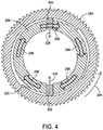
Fig. 4 is a partial sectional view of a lock/unlock mechanism (taken along the lines 4-4 ofFig. 3 ) that is shown inFigs. 2 and3 ; -
Fig. 5 is a front view of the apparatus shown inFig. 3 ; -
Fig. 6 is a sectional view taken along the lines 6-6 ofFig. 5 ; -
Fig. 7 is a partial sectional view of the interface between a driveshaft and a driven shaft; -
Fig. 8 is a perspective view of a system for applying mechanical stimulation to a plurality of biologic samples that are each contained in a biologic sample chamber; and -
Fig. 9 is a perspective view of an example with two biologic sample chambers and two actuator stages. - Biologic research and development may require the growth and/or testing of a large number of biologic samples over time. Such biologic research and development often involve mechanical stimulation of the individual biologic samples. And such mechanical stimulation is often not continuous nor the same for all biologic samples. For example, a researcher may choose to stimulate and/or characterize one biologic sample at a first force and frequency for a first time period (e.g., a fixed time period or until some biologic sample condition is achieved) and stimulate and/or characterize a second biologic sample at a different force and frequency for a different time period (e.g., a different fixed time period or until some other biologic sample condition is achieved).
- Electromagnetic actuators provide clean, precise, and repeatable mechanical stimulation to such biologic samples, but such actuators are often an expensive component to a biologic system. Some systems, such as the Multi-Chamber ElectroForce® BioDynamic® test instrument from Bose Corporation, provide multi-specimen mechanical stimulation using a shared motor. This type of system, however, cannot easily be scaled to a larger scale system capable of stimulating and characterizing a significantly greater number of biologic samples. Moreover, such a system lacks the ability to individually stimulate the specimens (at least with respect to mechanical stimulation). A system that provides the ability to use a number of motors that is less than the number of samples to individually stimulate multiple biologic samples allows a researcher to "time-shift" individual biologic sample stimulation periods so that the motor(s) (an expensive system component) may be better utilized than a motor on a system having individual motors for each biologic sample. Such a system allows for the customization of the mechanical stimulation profile since a motor(s) is dedicated to a biologic sample but only for a prescribed period of time. Such a system also provides a researcher more flexibility in specifying mechanical stimulation periods for individual biologic samples than systems that use a single motor (or set of motors) to stimulate multiple biologic samples simultaneously (such as the Multi-Chamber ElectroForce® BioDynamic® test instrument mentioned above).
-
FIG. 8 (described in further detail later in the application) shows an example of a biologic testing system that provides increased motor utilization while providing flexibility in mechanical stimulation profiles of biologic samples. In this example, asingle motor system 367 is moved by a controller between sixteen biologic sample chambers (e.g. 105A and 105B). The controller preferably includes a user interface that permits a researcher (or other user) to specify various parameters of the mechanical stimulation to create a stimulation profile for each biologic sample. Depending on the system capabilities, the stimulation parameters may include the duration of stimulation (e.g., fixed time period or variable based on achievement of a measured condition), the type of stimulation (tension, compression, torsion, bend, radial, shear, fluid flow, pressure, electrical, magnetic etc), the frequency and magnitude of stimulation, and any other relevant stimulation parameters. And the simulation profile for each biologic sample may be identical or different in one or more parameters. - Moving one or a small number of actuators to the chamber(s) is preferred over moving the chamber(s) to the actuator(s), particularly where a large number of chambers or a various or changing combination of actuator types is involved. This is because each chamber will often have tubes connected to it for supplying a fluid to the chamber and removing fluid from the chamber. These tubes can become tangled or snagged as the chambers are moved. Having to move a large number of chambers with their associated tubing would be much more complicated than moving one or a few actuators. Moving the chambers might also be detrimental to the samples contained in the chambers or affect their properties in a non-desirable and/or unknown way. Moving the chambers results in the biologic samples being subject to mechanical stimulation due to the movement that depending on the frequency and magnitude could negatively affect biologic sample properties and/or become an unknown stimulation parameter. Fixed actuators with movable chambers are less flexible for adapting the cadence and type of loading. For example, with turret style chamber movement, the cadence and sequence of sample stimulation is more rigidly constrained. Alternatively, the chambers could be fixed with a dedicated actuator or actuators for each sample chamber. Such an arrangement, however, would be inefficient and expensive.
-
FIG. 1 illustrates a front view of a portion of abiologic sample chamber 105. Typically, the biologic sample chamber is manually prepared in a clean environment by an operator using a dedicated set-up fixture (not shown). Thebiologic sample chamber 105 includes achamber housing 210 that encloses achamber volume 205. Thechamber housing 210 may include a transparent ortranslucent chamber window 220 allowing automated visual monitoring and measurement of abiologic sample 201. The biologic sample chamber may be configured to accommodate a variety of biologic sample grips (i.e. biologic sample holders) according to the type of biologic sample. Grips can be custom-made for a particular type of biologic sample. For example, pincher-type grips may be used to hold a strip such as a ligament, tendon, or skin biologic sample. Porous or non-porous platens may be used to hold disk-shaped biologic samples such as cartilage or bone. Three- or four-point bend fixtures may be used to condition biologic samples in the chamber such as bone. In the configuration shown inFIG. 1 , an upperbiologic sample grip 240 and a lowerbiologic sample grip 250 are configured to hold a tubularbiologic sample 201 such as a vessel with or without a valve, urethra, bladder or trachea. The tubular biologic sample grips each have an end fitting 255 such as, for example, a nozzle or barb fitting that holds an end of the tubular biologic sample. - Referring to
FIGs 1 and.2 , the lowerbiologic sample grip 250 is mechanically coupled to ashaft 260 that extends from thechamber housing 210 such that a free end of theshaft 260 is external to thechamber 105. Theshaft 260 is connected to afeature 262 that engages with an actuator (described below) that is used to apply a load in one or more axes (e.g. stress, strain, bend) to a biologic sample in the chamber. The lowerbiologic sample grip 250 and chamber housing (210) are connected by a flexible fluid seal that allows for unconstrained motion of the shaft relative to the fixed chamber. As such, thegrip 250 mechanically transmits a user-defined conditioning profile (i.e. load) generated by the actuator to the held biologic sample. The upperbiologic sample grip 240 may be set to a fixed position by the operator relative to thechamber housing 210, or in some cases may also utilize a seal to transmit motion or force to actuator(s) or sensor(s). - When initially setting up the
chamber 105, a operator removes thewindow 220 to secure thebiologic sample 201 to the biologic sample grips 240, 250. The operator then manually turns a thumb screw 261 (see alsoFig. 6 ) to lock the lower biologic sample grip in place. A non-damaging thumb screw is preferably used (e.g. brass dog point, soft flat point, etc). Alternatively, a manually activated shaft clamp collar could be used. Thewindow 220 is then secured to thechamber 105 to hermetically seal the chamber. A first end of a conduit 264 (e.g. tube) is connected to an opening in a left side of thechamber housing 210 by aquick connect fitting 266.Conduit 264 can be used to supply a fluid that may contain a nutrient to the external surfaces of the biologic sample in thechamber 105. A first end of a conduit 268 (e.g. tube) is connected to an opening in a right side of thechamber housing 210 by aquick connect fitting 272.Conduit 268 may be used to exhaust a fluid from thechamber 105. Quick connectfittings conduits - The operator then uses a pump (not shown) to fill up the
conduits chamber 105. In this example thechamber 105 will only be about half filled with fluid due to the locations of thefittings chamber 105 completely filled with fluid. The biologic sample grips 240, 250 may be hollow to allow additional nutrient flow through the grips and biologic sample during the conditioning protocol. This is enabled bychamber ports grips biologic sample 201, and an external nutrient fluid circuit (not shown). The details of the nutrient fluid management system and control along with the instrumentation and system controls that may be used is described inU.S. Patent 7,587,949 , herein incorporated by reference in its entirety. - With reference to
Fig. 2 , thechamber 105 with theconduits support structure 278 which can removably hold thebiologic sample chamber 105. Thestructure 278 may be contained within an incubator which can hold a large number of chambers and provide a controlled environment (e.g. temperature, humidity, gas environment) to the biologic samples. The operator aligns four mounting features (e.g. blind holes (not shown)) on the back of thechamber 105 with fouralignment pins 280 on thesupport structure 278 and presses thechamber 105 onto thesupport structure 278. Theshaft 260 is inserted through abore 281 in a radial clamping device such as a lock/unlock gear 283 that is part of thesupport structure 278. A set oflatches 282 is used to secure thechamber 105 to thestructure 278. -
Fig. 3 shows thechamber 105 mounted to thesupport structure 278 with thelatches 282 in a closed position. The operator then connectsfittings 274 and 276 (and thus the ends of theconduits 264 and 268) to respectivecommon conduit structures chamber 105 from thestructure 284. Thestructure 284 includes afluid supply container 287, afilter 288, and a pump 290 (e.g. a peristaltic or gear pump). In this example, an additional seven conduits can be connected to thestructure 284. This arrangement allows up to eight biologic sample chambers to be supplied with fluid from asingle supply container 287,filter 288 and pump 290. In addition, thecommon conduit structures conduits - Likewise, fluid is transferred from the
chamber 105 through theconduit 268 into thestructure 286. Fluid from up to an additional seven chambers can be transferred into thestructure 286. Thestructure 286 is mostly made up of afluid container 292. In an alternative arrangement in which the fluid transferred from the chamber 105 (and other chambers) is to be recycled, thestructure 286 is eliminated and the fitting 276 is connected to thecontainer 287. This results in a closed loop fluid circulation system. The dynamic pressure and/or flow of the fluid can be controlled to apply additional loads continuously or periodically on thebiologic sample 201 in thechamber 105. - Referring to
Figs. 3 and4 , the operator next manually rotates thegear 283 in the direction of an arrow 294 (counterclockwise). This rotation causes relative motion (represented by arrows 296) between thegear 283 and astationary hub 298 which is fixed to thestructure 278. The relative motion causes acam surface 300 to push a pair of gripingelements arrows elements shaft 260 of thechamber 105, thus holding theshaft 260 in a fixed position. As a last step, the operator rotates the thumb screw 261 (seeFig. 6 ) to release theshaft 260 from the grip of thethumb screw 261. The previous steps can be repeated for as many biologic samples and biologic sample chambers as are desired in the stimulation regime. As mentioned above, a large number of chambers can be placed into an incubator in which one or more actuators will stimulate the biologic samples. Once the biologic sample chambers are placed into the incubator, the incubator is closed up and the biologic sample stimulation regimen is commenced. More biologic samples can be added to or removed from the structure during the stimulation regime without affecting the existing or remaining biologic samples. - Turning to
Figs. 5 and6 and the biologic sample-engagement steps, the system now automatically positions anactuator stage 310 underneath thestructure 278 using a machine positioning device 311 (e.g. a multiple axes machine vision system) which aligns on afeature 313 on the bottom of thesupport structure 278. Thestage 310 is then automatically moved in adirection 312 to cause adriveshaft 314 to engage into the bottom of theshaft 260. This movement also causes adriveshaft 316 to be engaged into the bottom of a radial driving device such as adrive gear 318. As a result,stimulation actuators 342 and 344 (described further below) are automatically moved into a position proximate to thechamber 105 in which these actuators can transmit a load to thebiologic sample 201 via a transmission path that includes theshaft 260 and thebiologic sample holder 250. - With reference to
Fig. 7 , the interface between thedriveshaft 314 and theshaft 260 will be described. After thedriveshaft 314 has been inserted into theshaft 260, aninternal pin 320 is moved in thedirection 322, for example, by an electric solenoid. This movement causes thepin 320 to press against alock component 324. There are multiple radially spacedcomponents 324, but only one is shown inFig. 7 . The pressure from thepin 320 against thecomponents 324 presses thecomponents 324 into rigid compression with aninternal surface 326 of theshaft 260 to create a rigid joint. The frictional resistance supplied by thecomponents 324 against thesurface 326 temporarily locks thedrive shaft 314 to theshaft 260. As such, thedriveshaft 314 can transfer load, displacement, torque and/or rotation to theshaft 260 with high rigidity. This same arrangement is used to temporarily lock thedriveshaft 316 to the bottom of the drive gear 318 (seeFig. 6 ). - Referring to
Fig. 6 , amicrocontroller 332 controls operation of all of the actuators (described below) and measurement of sensors in the motor assemblies on thestage 310. Cabling 334 supplies electrical power to theactuator stage 310 and control signals from a main controller (not shown) to themicrocontroller 332. After the stage is moved into the position shown inFig. 6 and the drive-shafts shaft 260 andgear 318, themicrocontroller 332 causes therotary engagement actuator 338 to operate to turndriveshaft 316 which turnsdrive gear 318.Gear 283 is turned in a clockwise direction (as viewed inFig. 4 ) which releases the pressure ongrips 302/304 and unlocks theshaft 260 from thegrips 302/304. Movement of theshaft 260 is now controlled by thedrive shaft 314 and thestimulation actuators - One or more measurement devices can be used to obtain characteristics of the sample. These devices can travel with the actuator stage (or a separate measurement stage) and/or remain with the sample or chamber even when the actuator stage is moved away from the chamber. The load on the sample can be measured by monitoring electrical current in
motor 342 or by a load cell in the force transmission path to the sample. A measurement device 333 (e.g. a laser micrometer or CCD camera) is supported on amember 335 that extends from thestage 310. Thedevice 333 is used to measure a characteristic (e.g. dimension) of thebiologic sample 201 at any time while thestage 310 is in the position shown inFig. 6 . Other types of sensors include those to measure, for example, temperature, torque, rotation, strain, electrical properties, magnetic field, and chemical composition. - The previous steps outline the engagement of the
stimulation actuators biologic sample 201. Now that theactuators microcontroller 332 now operates thelinear actuator 342 and/or therotary actuator 344 to move thedriveshaft 314 which in turn moves theshaft 260. The linear actuator 342 (e.g. a linear electro-magnetic motor) can move thedriveshaft 314 back and forth in the directions shown by two-headedarrow 346. This can be in various control modes depending on the desired stimulation profile (e.g. stress or strain control). The rotary actuator 344 (e.g. a rotary electro-magnetic motor) can rotate thelinear actuator 342 in either torque (stress) or rotation (strain) control and thus thedrive shaft 314 about an axis running down the center of thedrive shaft 314. Movement of theshaft 260 causes the lowerbiologic sample grip 250 to likewise move. This movement in turn applies tension, compression and/or rotary stresses to thebiologic sample 201. As such, theactuators biologic sample 201 that is held by thebiologic sample holders microcontroller 332 can vary the duration, frequency and amplitude of the linear and rotary motion imparted to theshaft 260 to control the mechanical stimulation that is applied to thebiologic sample 201. At various stages of the development cycle, alternate stimulation actuators can be deployed and engaged. These various sequences can be manually pre-described by the operator or automatically adaptive based on biologic sample measurements acquired and analyzed during previous loading cycles. - The operator (user) can define a conditioning profile with fixed periods of conditioning and rest for one or more biologic samples. Alternatively, the operator can define a conditioning profile that depends on a variable. For example, a 1 HZ tension-compression load can be applied to the biologic sample until the sample elongates by a certain specified percentage (e.g. 20%)If the
microcontroller 332 and/or the main controller (mentioned above) is going to base the conditioning on a variable (e.g. elongation), the chamber will need the appropriate sensor to measure the variable. A signal from such sensor will be fed back to themicrocontroller 332 and/or the main controller via a wired and/or wireless transmission path. In some embodiments a user interface (not shown) for themicrocontroller 332 and/ or main controller may be collocated with the system or it may be remote from the rest of the system. For example, a web based user interface can be used that permits a researcher to program a conditioning profile from anywhere. The entire system with multiple biologic sample chambers may be located within an incubator, or there may be multiple incubators for different sets of chambers, or each chamber can be located within its own incubator. In another example, a fluid pump such as a bellows or diaphragm (not shown) is included in thechamber 105. An additional actuator (not shown) is included on thestage 310 and operates the fluid pump to pulse pressure waves through fluid inside thechamber 105, thereby providing further stimulation to thebiologic sample 201. - Once the mechanical stimulation cycle for the
biologic sample 201 has been completed (i.e. themicrocontroller 332 has stopped the linear androtary actuators 342 and 344), the following sequence occurs to disengage theactuator stage 310 from thesupport structure 278. First, the microcontroller operates one or bothactuators actuators 342 and 344). Next, anelectric shaft clamp 352, which to this point has locked ashaft 353 in place, is released by themicrocontroller 332. Theshaft 353 may now be moved up or down relative thesupport structure 278. A spring, or spring set, 355 is connected at a bottom end to a feature projecting from theshaft 353 and at a top end to thesupport structure 278. Thespring 355 is in tension at this point and is arranged to maintain theshaft 353 and thuschamber 105 in the same position as it was beforeclamp 352 was released. Instead of or in addition to thespring 355, another force provider such as a pneumatic, hydraulic, magnetic or other system may be provided. - If it is desired to automatically maintain a constant load on the
sample 201 after thestage 310 is moved away, the following steps may be taken. The microcontroller operates one or bothactuators actuators 342 and 344). For example, theshaft 314 can be moved downward to place thesample 201 in tension. Thespring 355 provides force in an upward direction to bias thechamber 105 upwards. A relativelylong spring 355 is used in order to keep a substantially constant force on thesample 201 even if the sample relaxes (e.g. elongates). If it is desired to automatically adjust the load on thesample 201 over time, thespring 355 is replaced by, for example, a pneumatic or hydraulic force provider. The steps described above in this paragraph are used only if thesample 201 is to be left in a load-controlled state (to prevent relaxation and loss of specimen load and stress_. These steps are skipped it is desired to leave the sample in a fixed displacement position. - The
microcontroller 332 now operates therotary actuator 338 to turn thegear 283 in a counter-clockwise direction (seeFig. 4 ) via thedrive gear 318. This rotation drives thegrips 302/304 in the respective directions ofarrows 306/308, thereby impinging thegrips 302/304 on theshaft 260. This has the effect of locking theshaft 260 in place. - With reference to
Figs 6 and.7 , thepin 320 is now moved by a solenoid (not shown) in a direction opposite to that shown by thearrow 322. As such, thepin 320 is disengaged from thecomponents 324. The frictional resistance of thecomponents 324 against thesurface 326 is thereby released which allows thedriveshaft 314 to be withdrawn from theshaft 260. This same procedure is used at the interface of thedriveshaft 316 from thegear 318. Now theactuator stage 310 is lowered in a direction opposite to thearrow 312 to disengage thedrive shafts shaft 260 and thegear 318. Thestage 310 can now be moved to another chamber/support structure to provide mechanical stimulation to a biologic sample in that chamber. - Turning to
Fig. 8 , an example is provided in which a two-dimensional array ofbiologic sample chambers Fig. 8 in order to avoid over-clutteringFig. 8 . Theactuator stage 310 is supported by a first screw-drive system 360 which can be operated to move thestage 310 in the directions shown by two-headedarrow 362. Thesystem 362 is supported by aplatform 364 of a second screw-drive system 366 which can be operated to move theplatform 364 in the directions shown by a two-headedarrow 368. A solenoid or other type of drive system (not shown) is located between thesystem 360 and theplatform 364, and is used to move thesystem 360 in the directions shown by a two-headedarrow 370. As such, theactuator stage 310 can be moved in three dimensions to connect and disconnect thedrive shafts 314 and 316 (Fig. 6 ) from the various chambers. - For example, the
stage 310 can be automatically lowered from a first position in which it is engaged with thechamber 105A to a second position in which theactuators chamber 105A. Thestage 310 can then be automatically moved to a third position proximate to a secondbiologic sample chamber 105B having a second biologic sample holder therein so that theactuators shaft 260 and the second biologic sample holder. - Referring to
Fig. 9 , an example is shown in which twostages support structures biologic sample chambers stages stage 310 described above.Stages stages stage 380 may have a lower power/stroke actuator for providing a smaller load to a biologic sample during an earlier stage of biologic sample loading. In a later stage of biologic sample loading,stage 382 can be automatically moved into the position previously occupied bystage 380 in order to supply a larger load to the same biologic sample with a higher power/stroke actuator. Structure for moving thestages Fig 9 , but structure similar to that shown inFig. 8 can be used to move each of these stages from engagement withchamber 105A toengagement chamber 105B to a neutral position not engaged with either chamber. - Referring to
Fig. 6 , another example will be described. A second set of gears (not shown) similar togears chamber 105 and supported by thesupport structure 278. An additional shaft (not shown) similar toshaft 260 extends from the top of thechamber 260. Thestage 310 can be moved so thatshafts actuators sample 201 from above the chamber. Alternatively, an additional stage that may be the same as or different from thestage 310 is moved above thechamber 105. This can be done either when stage 110 is positioned under thechamber 105 or when the stage 110 is remote from thechamber 105. As such, thesample 201 can receive stimulation from both sample grips 240 and 250. If the additional stage has one or more actuators that are different from the actuators on thestage 310, then a different type of stimulation can be provided to thesample 201 by the actuator(s) of the additional stage compared to the actuators342 and 344 of thestage 310. - Having thus described at least illustrative embodiments, various modifications and improvements will readily occur to those skilled in the art and are intended to be within the scope of the invention. Accordingly, the foregoing description is by way of example only and is not intended as limiting. The invention is limited only as defined in the following claims and the equivalents thereto.
Claims (15)
- A system for applying mechanical stimulation to a biologic sample (201), the system comprising:a first biologic sample chamber (105) having a biologic sample holder (240) therein;a support structure (278) for holding the first biologic sample chamber (105);a first actuator (342) that can supply a mechanical load to a biologic sample (201) held by the biologic sample holder (240), the actuator configured to move into a first position proximate to the chamber in which the actuator can transmit the load to the biologic sample (201) via a first transmission path that includes the biologic sample holder (240);a controller (332) configured to automatically move the first actuator (342) into the first position; characterized by a second actuator (344) which is substantially different from the first actuator (342), the second actuator(344) being automatically movable into the first position when the first actuator (342) is not in the first position so that the second actuator (344) can transmit a load to the first biologic sample holder via the first transmission path.
- The system of claim 1, wherein the first actuator (342) can be automatically moved to a second position in which the actuator cannot transmit the load to the biologic sample (201).
- The system of claim 1, wherein the first actuator (342) can be automatically moved to a third position proximate to a second biologic sample chamber having a second biologic sample holder therein so that the first actuator (342) can transmit a load to a biologic sample held by the second biologic sample holder via a transmission path that includes the second biologic sample holder.
- The system of claim 1, wherein the second actuator (344) can be automatically moved to a second position in which the second actuator (344) cannot transmit a load to the first biologic sample, wherein the second actuator (344) can be automatically moved to a third position proximate to a second biologic sample chamber having a second biologic sample holder therein so that the second actuator (344) can transmit a load to a biologic sample (201) held by the second biologic sample holder via a transmission path that includes the second biologic sample holder when the first actuator (342) is not in the third position.
- The system of claim 4, wherein each biologic sample chamber includes a first opening through which a fluid can be supplied to a biologic sample in that chamber, and wherein a first end of respective supply conduits is connected to each opening for conducting fluid to that opening, a second end of each respective conduit is connected to a first common conduit structure and wherein each biologic sample chamber includes a second opening through which a fluid can be transferred from that chamber, and wherein a first end of respective exhaust conduits is connected to each second opening for conducting fluid from the second opening, a second end of each respective conduit is connected to a second common conduit structure.
- The system of claim 1, wherein the biologic sample (201) is a living tissue sample.
- The system of claim 1, wherein the actuator is an electromagnetic actuator.
- The system of claim 1, wherein the controller (332) causes the actuator to deliver the load.
- The system of claim 8, wherein the controller (332) is programmable by a user.
- The system of claim 9, wherein the controller (332) is configured to deliver the load for a user-defined period of time.
- The system of claim 9, wherein the controller (332) is configured to deliver the load according to a user-defined conditioning profile.
- The system of claim 11, wherein the user-defined conditioning profile delivers the load to the biologic sample (201) based upon one or more fixed-time profiles.
- The system of claim 11, wherein the user-defined conditioning profile delivers the load to the biologic sample (201) based upon a value of a measured variable.
- The system of claim 13, wherein the measured variable consists of one or more of the following: temperature in the chamber, pH in the chamber, and a property of the biologic sample.
- The system of claim 2, wherein after the actuator is moved away from the first position, a load on the biologic sample (201) can be automatically maintained.
Applications Claiming Priority (2)
| Application Number | Priority Date | Filing Date | Title |
|---|---|---|---|
| US13/332,495 US9606035B2 (en) | 2011-12-21 | 2011-12-21 | System for mechanical stimulation and characterization of biologic samples |
| PCT/US2012/065756 WO2013095834A1 (en) | 2011-12-21 | 2012-11-19 | System for mechanical stimulation and characterization of biologic samples |
Publications (2)
| Publication Number | Publication Date |
|---|---|
| EP2795286A1 EP2795286A1 (en) | 2014-10-29 |
| EP2795286B1 true EP2795286B1 (en) | 2017-08-02 |
Family
ID=47297460
Family Applications (1)
| Application Number | Title | Priority Date | Filing Date |
|---|---|---|---|
| EP12798104.1A Active EP2795286B1 (en) | 2011-12-21 | 2012-11-19 | System for mechanical stimulation and characterization of biologic samples |
Country Status (6)
| Country | Link |
|---|---|
| US (1) | US9606035B2 (en) |
| EP (1) | EP2795286B1 (en) |
| CN (1) | CN104011526B (en) |
| AU (1) | AU2012355851B2 (en) |
| CA (1) | CA2857399C (en) |
| WO (1) | WO2013095834A1 (en) |
Families Citing this family (11)
| Publication number | Priority date | Publication date | Assignee | Title |
|---|---|---|---|---|
| US9353345B2 (en) | 2013-07-12 | 2016-05-31 | Ta Instruments-Waters L.L.C. | Securing apparatus and method |
| US11034928B2 (en) * | 2014-07-23 | 2021-06-15 | Clemson University Research Foundation | Modular bioreactor, compliance chamber for a bioreactor, and cell seeding apparatus |
| ES2562984B1 (en) * | 2014-09-09 | 2016-12-20 | Fundació Institut D'investigació Biomèdica De Bellvitge (Idibell) | Extensimeter for biological structures |
| US20170362558A1 (en) * | 2014-12-11 | 2017-12-21 | Oxford University Innovation Limited | Biological sample actuator |
| US10287548B2 (en) * | 2016-06-29 | 2019-05-14 | General Electric Company | Method and device for closed system culture of cartilage tissue |
| RU2645455C1 (en) * | 2017-04-27 | 2018-02-21 | Рубен Вагеевич Оганесян | Bioreactor for growing tissue engineering structures |
| US10379106B2 (en) * | 2017-07-20 | 2019-08-13 | Seqvera Ltd. Oy | In vitro method for measurement and model-free evaluation of time-invariant biomaterials functions |
| US11843301B2 (en) | 2019-01-22 | 2023-12-12 | Waters Technologies Corporation | Linear motor |
| TW202039818A (en) * | 2019-04-25 | 2020-11-01 | 中國醫藥大學 | Cell sample stimulation device including a base seat unit, at least one movable member, and at least one magnetic attraction member |
| US20230064704A1 (en) * | 2021-11-11 | 2023-03-02 | Clemson University Research Foundation | In vitro myocardial tissue screening devices, systems, and methods |
| EP4692305A1 (en) | 2024-08-09 | 2026-02-11 | Cherry Biotech SAS | Method for controlling pressure and dissolved gas composition and/or ph of a volume of liquid cell culture medium contained in at least one closed chamber which comprises a cultured biological entity |
Family Cites Families (69)
| Publication number | Priority date | Publication date | Assignee | Title |
|---|---|---|---|---|
| US4833083A (en) | 1987-05-26 | 1989-05-23 | Sepragen Corporation | Packed bed bioreactor |
| US5798261A (en) | 1989-10-31 | 1998-08-25 | The United States Of America As Represented By The Administrator Of The National Aeronautics And Space Administration | Distributed pore chemistry in porous organic polymers |
| US5216723A (en) | 1991-03-11 | 1993-06-01 | Bose Corporation | Permanent magnet transducing |
| US5306305A (en) | 1992-01-31 | 1994-04-26 | Etex Corporation | Methods of coating implants with bony structure |
| US5776748A (en) | 1993-10-04 | 1998-07-07 | President And Fellows Of Harvard College | Method of formation of microstamped patterns on plates for adhesion of cells and other biological materials, devices and uses therefor |
| US5931969A (en) | 1994-07-29 | 1999-08-03 | Baxter International Inc. | Methods and apparatuses for treating biological tissue to mitigate calcification |
| DE4429380C1 (en) | 1994-08-15 | 1996-04-25 | Biotronik Mess & Therapieg | Method for producing a non-collapsing intravascular vascular prosthesis (stent) |
| US5792603A (en) | 1995-04-27 | 1998-08-11 | Advanced Tissue Sciences, Inc. | Apparatus and method for sterilizing, seeding, culturing, storing, shipping and testing tissue, synthetic or native, vascular grafts |
| US5846828A (en) | 1995-06-07 | 1998-12-08 | Advanced Tissue Sciences | Apparatus and method for sterilizing, seeding, culturing, storing, shipping, and testing tissue, synthetic, or mechanical heart valves orvalve segments |
| US6121042A (en) | 1995-04-27 | 2000-09-19 | Advanced Tissue Sciences, Inc. | Apparatus and method for simulating in vivo conditions while seeding and culturing three-dimensional tissue constructs |
| US5843766A (en) | 1995-06-07 | 1998-12-01 | Advanced Tissue Sciences, Inc. | Apparatus for the growth and packaging of three dimensional tissue cultures |
| US5763267A (en) | 1996-04-16 | 1998-06-09 | Advanced Tissue Sciences | Apparatus for the large scale growth and packaging of cell suspensions and three-dimensional tissue cultures |
| US5827729A (en) | 1996-04-23 | 1998-10-27 | Advanced Tissue Sciences | Diffusion gradient bioreactor and extracorporeal liver device using a three-dimensional liver tissue |
| FR2765356B1 (en) | 1997-06-25 | 2004-02-13 | Eastman Kodak Co | NEW METHOD FOR ATTACHING A PHOTOGRAPHIC PRODUCT |
| CN1111689C (en) | 1997-11-17 | 2003-06-18 | 大金工业株式会社 | Refrigerating apparatus |
| US6066495A (en) | 1998-03-05 | 2000-05-23 | Tissue Engineering, Inc. | Methods and apparatus for the conditioning of ligament replacement tissue |
| US6641576B1 (en) | 1998-05-28 | 2003-11-04 | Georgia Tech Research Corporation | Devices for creating vascular grafts by vessel distension using rotatable elements |
| US6207405B1 (en) | 1998-06-29 | 2001-03-27 | S. C. Johnson & Son, Inc. | Pilot drain system for rapid biofilm formation |
| US6080581A (en) | 1998-07-02 | 2000-06-27 | Charles Daniel Anderson | Culture vessel for growing or culturing cells, cellular aggregates, tissues and organoids and methods for using same |
| WO2000011953A1 (en) | 1998-09-01 | 2000-03-09 | Penn State Research Foundation | Method and apparatus for aseptic growth or processing of biomass |
| FR2784284B1 (en) | 1998-10-13 | 2000-12-15 | Natural Implant Sa | PROCESS FOR THE PREPARATION OF A DENTAL IMPLANT BY IMMERSION IN A CULTURE OF MESENCHYMAL CELLS, CELL CULTURE DEVICE FOR THE PREPARATION OF SAID IMPLANT AND IMPLANT OBTAINED |
| US7615373B2 (en) | 1999-02-25 | 2009-11-10 | Virginia Commonwealth University Intellectual Property Foundation | Electroprocessed collagen and tissue engineering |
| US20020090725A1 (en) | 2000-11-17 | 2002-07-11 | Simpson David G. | Electroprocessed collagen |
| US6592623B1 (en) | 1999-08-31 | 2003-07-15 | Virginia Commonwealth University Intellectual Property Foundation | Engineered muscle |
| US6979308B1 (en) | 1999-06-03 | 2005-12-27 | University Of North Carolina At Chapel Hill | Bioreactor design and process for engineering tissue from cells |
| US6632651B1 (en) | 1999-07-06 | 2003-10-14 | Ramot At Tel Aviv University Ltd. | Tissue maintenance system that applies rhythmic pulses of pressure |
| EP2290050B1 (en) | 1999-09-08 | 2012-06-13 | Levitronix Technologies, LLC | Bioreactor |
| US6503273B1 (en) | 1999-11-22 | 2003-01-07 | Cyograft Tissue Engineering, Inc. | Tissue engineered blood vessels and methods and apparatus for their manufacture |
| US6432712B1 (en) | 1999-11-22 | 2002-08-13 | Bioscience Consultants, Llc | Transplantable recellularized and reendothelialized vascular tissue graft |
| DE10026540A1 (en) | 2000-05-27 | 2001-11-29 | Gfe Met & Mat Gmbh | Object, especially implant |
| AU2001284968B2 (en) | 2000-08-16 | 2006-12-21 | Duke University | Decellularized tissue engineered constructs and tissues |
| US6632658B1 (en) | 2000-08-18 | 2003-10-14 | Levitronix Llc | Bioreactor and method for fluidly suspending a product |
| US6864084B2 (en) | 2000-08-18 | 2005-03-08 | Levitronix Llc | Bioreactor and method for fluidly suspending a product |
| US20020146817A1 (en) | 2000-10-02 | 2002-10-10 | Cannon Thomas F. | Automated bioculture and bioculture experiments system |
| AU2001294922A1 (en) | 2000-10-02 | 2002-04-15 | Thomas F. Cannon | Automated bioculture and bioculture experiments system |
| AU2002230396B2 (en) | 2000-10-06 | 2012-06-07 | Krstec, Victor | System and method to simulate hemodynamics |
| US7553662B2 (en) | 2000-12-22 | 2009-06-30 | Keele University | Culturing tissue using magnetically generated mechanical stresses |
| WO2002060507A1 (en) | 2001-01-30 | 2002-08-08 | Isotis S.A. | A method for applying a bioactive coating on a medical device |
| US7326564B2 (en) | 2001-02-20 | 2008-02-05 | St. Jude Medical, Inc. | Flow system for medical device evaluation and production |
| DE60210588D1 (en) | 2001-03-02 | 2006-05-24 | Univ Laval Quebec | PLASMA SURFACE TREATMENT PROCESS FOR THROMBOGENIC REDUCTION |
| FR2821853B1 (en) | 2001-03-09 | 2003-05-16 | Natural Implant Sa | BIOREACTOR FOR THIN FILM CULTIVE TISSUE AND USES |
| US20040248722A1 (en) | 2001-03-26 | 2004-12-09 | Chirstopher Mason | Methods for forming hardened tubes and sheets |
| WO2002078439A2 (en) | 2001-03-30 | 2002-10-10 | The Arizona Board Of Regents On Behalf Of The University Of Arizona | Prevascularized constructs for implantation to provide blood perfusion |
| US7052829B2 (en) | 2001-03-30 | 2006-05-30 | The Arizona Board Of Regents On Behalf Of The University Of Arizona | Prevascularized constructs for implantation to provide blood perfusion |
| GB0121986D0 (en) | 2001-09-11 | 2001-10-31 | Isis Innovation | Method and structure for growing living organic tissue |
| US20020106625A1 (en) | 2002-02-07 | 2002-08-08 | Hung Clark T. | Bioreactor for generating functional cartilaginous tissue |
| EP1485465A2 (en) | 2002-02-28 | 2004-12-15 | Arizona Board of Regents, acting for and on behalf of Arizona State University | Microcapillary bioreactor for growth of biological tissue |
| US7348175B2 (en) | 2002-03-15 | 2008-03-25 | St3 Development Corporation | Bioreactor with plurality of chambers for conditioning intravascular tissue engineered medical products |
| US8492140B2 (en) | 2002-04-08 | 2013-07-23 | Octane Biotech Inc. | Automated tissue engineering system |
| US20040219659A1 (en) | 2002-04-22 | 2004-11-04 | Altman Gregory H. | Multi-dimensional strain bioreactor |
| US6875605B1 (en) | 2002-08-21 | 2005-04-05 | Florida State University Research Foundation, Inc. | Modular cell culture bioreactor and associated methods |
| US6943008B1 (en) | 2002-08-21 | 2005-09-13 | Florida State University Research Foundation, Inc. | Bioreactor for cell culture |
| US20040241835A1 (en) | 2003-02-06 | 2004-12-02 | Hutmacher Dietmar W. | Dual axis bioreactor, system and method for growing cell or tissue cultures |
| US7604987B2 (en) | 2003-02-06 | 2009-10-20 | National University Of Singapore | Bioreactor for growing cell or tissue cultures |
| WO2004076608A2 (en) | 2003-02-26 | 2004-09-10 | Georgia Tech Research Corporation | Bioreactor and methods for tissue growth and conditioning |
| US7494811B2 (en) | 2003-05-01 | 2009-02-24 | Lifenet Health | In vitro growth of tissues suitable to the formation of bone and bone forming tissue formed thereby |
| US7410792B2 (en) * | 2003-09-19 | 2008-08-12 | St3 Development Corporation | Instrumented bioreactor with material property measurement capability and process-based adjustment for conditioning tissue engineered medical products |
| US20050095711A1 (en) | 2003-11-01 | 2005-05-05 | More Robert B. | Bioreactor for growing engineered tissue |
| US7662615B2 (en) | 2004-07-27 | 2010-02-16 | Chung Yuan Christian University | System and method for cultivating cells |
| TWI294912B (en) | 2005-04-04 | 2008-03-21 | Nat Univ Tsing Hua | Bioreactor for cultivating tissue cells |
| WO2006113382A2 (en) | 2005-04-15 | 2006-10-26 | Wake Forest University Health Sciences | Bioreactor system and method of enhancing functionality of muscle cultured in vitro |
| US7913573B2 (en) * | 2006-01-13 | 2011-03-29 | Mts Systems Corporation | Orthopedic simulator with a multi-axis slide table assembly |
| US7617744B2 (en) * | 2006-01-13 | 2009-11-17 | Mts Systems Corporation | Transmission for torque transfer with axial compliance |
| US7587949B2 (en) | 2007-07-20 | 2009-09-15 | Bose Corporation | System and method for stimulation and characterization of biologic materials |
| US7694593B2 (en) * | 2008-05-13 | 2010-04-13 | Bose Corporation | Multi-sample conditioning system |
| ITTO20080426A1 (en) | 2008-06-05 | 2009-12-06 | Centro Biotecnologie Avanzate | BIOREACTOR, IN PARTICULAR FOR THE GENERATION OF ENGINEERED FABRICS |
| US7966890B2 (en) | 2008-06-25 | 2011-06-28 | Bose Corporation | High frequency multi-axis simulation system |
| US8444935B2 (en) | 2009-06-12 | 2013-05-21 | Bose Corporation | Multiple-specimen device testing with particle measurement |
| US20130059324A1 (en) * | 2010-05-11 | 2013-03-07 | The University Of Kansas | Systems and methods for mechanically strained cell culture |
-
2011
- 2011-12-21 US US13/332,495 patent/US9606035B2/en active Active
-
2012
- 2012-11-19 CN CN201280063580.8A patent/CN104011526B/en active Active
- 2012-11-19 CA CA2857399A patent/CA2857399C/en active Active
- 2012-11-19 WO PCT/US2012/065756 patent/WO2013095834A1/en not_active Ceased
- 2012-11-19 EP EP12798104.1A patent/EP2795286B1/en active Active
- 2012-11-19 AU AU2012355851A patent/AU2012355851B2/en active Active
Non-Patent Citations (1)
| Title |
|---|
| None * |
Also Published As
| Publication number | Publication date |
|---|---|
| CA2857399A1 (en) | 2013-06-27 |
| CA2857399C (en) | 2017-04-18 |
| EP2795286A1 (en) | 2014-10-29 |
| CN104011526A (en) | 2014-08-27 |
| US20130160577A1 (en) | 2013-06-27 |
| AU2012355851B2 (en) | 2014-10-30 |
| WO2013095834A1 (en) | 2013-06-27 |
| AU2012355851A1 (en) | 2014-06-26 |
| CN104011526B (en) | 2017-06-09 |
| US9606035B2 (en) | 2017-03-28 |
Similar Documents
| Publication | Publication Date | Title |
|---|---|---|
| US9606035B2 (en) | System for mechanical stimulation and characterization of biologic samples | |
| CA2757254C (en) | Deformable transportable bioreactor chamber | |
| JP6987425B2 (en) | Methods and equipment for closed system culture of cartilage tissue | |
| AU2017340975A1 (en) | Coupling for a robotic surgical instrument | |
| ITTO20080426A1 (en) | BIOREACTOR, IN PARTICULAR FOR THE GENERATION OF ENGINEERED FABRICS | |
| CN103622763B (en) | Valve fatigue-life testing device | |
| CN113567322B (en) | A test device and method for studying the mechanical properties of porous media caused by water pressure | |
| ITMI20071712A1 (en) | AUTOMATED MACHINE FOR THE WEIGHT OF DEAD WEIGHTS FOR THE CALIBRATION OF EXTENSIMETRIC LOAD CELLS | |
| CN107314935B (en) | A gear-structured universal testing machine variable load ratio double-pull test device | |
| US20190064304A1 (en) | Soft tissue simulator for magnetic resonance testing and method for simulated testing | |
| CN113390720B (en) | Off-line in-situ stretching device for X-ray diffraction experiment | |
| CN110987642A (en) | Rigid-flexible composite true triaxial loading device of rubber film outer wrapping loading plate | |
| US12012583B2 (en) | Six-sample universal mechanical stimulation device for soft tissue | |
| CN212008136U (en) | A rigid-flexible composite true triaxial loading device with a rubber film outer loading plate | |
| RU156848U1 (en) | TENSION TEST DEVICE | |
| Seneci et al. | Design of a smart 3D-printed wristed robotic surgical instrument with embedded force sensing and modularity | |
| KR101374185B1 (en) | Stent test equipment for elongation, bending and radial compression of a stent | |
| CN218271659U (en) | High-flux test module and device capable of providing different strain loads | |
| CN115493922A (en) | High-throughput testing module and device capable of providing different stress-strain loads | |
| CN206618632U (en) | Stretching extruding test system and the test fixture for extension test | |
| CN121521662B (en) | Anti-fatigue test device for bone implant | |
| CN216208101U (en) | Clamp and preloading device | |
| CN120253042A (en) | Fastener surface stress detection device and detection method | |
| SU1420125A1 (en) | Bench for testing and investigating apparatus with power martensite drives for driving holes in soil | |
| CN119335293A (en) | An electromagnetic compatibility test device |
Legal Events
| Date | Code | Title | Description |
|---|---|---|---|
| PUAI | Public reference made under article 153(3) epc to a published international application that has entered the european phase |
Free format text: ORIGINAL CODE: 0009012 |
|
| 17P | Request for examination filed |
Effective date: 20140604 |
|
| AK | Designated contracting states |
Kind code of ref document: A1 Designated state(s): AL AT BE BG CH CY CZ DE DK EE ES FI FR GB GR HR HU IE IS IT LI LT LU LV MC MK MT NL NO PL PT RO RS SE SI SK SM TR |
|
| DAX | Request for extension of the european patent (deleted) | ||
| RAP1 | Party data changed (applicant data changed or rights of an application transferred) |
Owner name: TA INSTRUMENTS-WATERS LLC |
|
| GRAP | Despatch of communication of intention to grant a patent |
Free format text: ORIGINAL CODE: EPIDOSNIGR1 |
|
| STAA | Information on the status of an ep patent application or granted ep patent |
Free format text: STATUS: GRANT OF PATENT IS INTENDED |
|
| INTG | Intention to grant announced |
Effective date: 20170220 |
|
| GRAS | Grant fee paid |
Free format text: ORIGINAL CODE: EPIDOSNIGR3 |
|
| GRAA | (expected) grant |
Free format text: ORIGINAL CODE: 0009210 |
|
| STAA | Information on the status of an ep patent application or granted ep patent |
Free format text: STATUS: THE PATENT HAS BEEN GRANTED |
|
| AK | Designated contracting states |
Kind code of ref document: B1 Designated state(s): AL AT BE BG CH CY CZ DE DK EE ES FI FR GB GR HR HU IE IS IT LI LT LU LV MC MK MT NL NO PL PT RO RS SE SI SK SM TR |
|
| REG | Reference to a national code |
Ref country code: CH Ref legal event code: EP Ref country code: AT Ref legal event code: REF Ref document number: 915001 Country of ref document: AT Kind code of ref document: T Effective date: 20170815 |
|
| REG | Reference to a national code |
Ref country code: IE Ref legal event code: FG4D |
|
| REG | Reference to a national code |
Ref country code: DE Ref legal event code: R096 Ref document number: 602012035406 Country of ref document: DE |
|
| REG | Reference to a national code |
Ref country code: NL Ref legal event code: MP Effective date: 20170802 |
|
| REG | Reference to a national code |
Ref country code: AT Ref legal event code: MK05 Ref document number: 915001 Country of ref document: AT Kind code of ref document: T Effective date: 20170802 |
|
| REG | Reference to a national code |
Ref country code: LT Ref legal event code: MG4D |
|
| PG25 | Lapsed in a contracting state [announced via postgrant information from national office to epo] |
Ref country code: LT Free format text: LAPSE BECAUSE OF FAILURE TO SUBMIT A TRANSLATION OF THE DESCRIPTION OR TO PAY THE FEE WITHIN THE PRESCRIBED TIME-LIMIT Effective date: 20170802 Ref country code: NL Free format text: LAPSE BECAUSE OF FAILURE TO SUBMIT A TRANSLATION OF THE DESCRIPTION OR TO PAY THE FEE WITHIN THE PRESCRIBED TIME-LIMIT Effective date: 20170802 Ref country code: AT Free format text: LAPSE BECAUSE OF FAILURE TO SUBMIT A TRANSLATION OF THE DESCRIPTION OR TO PAY THE FEE WITHIN THE PRESCRIBED TIME-LIMIT Effective date: 20170802 Ref country code: HR Free format text: LAPSE BECAUSE OF FAILURE TO SUBMIT A TRANSLATION OF THE DESCRIPTION OR TO PAY THE FEE WITHIN THE PRESCRIBED TIME-LIMIT Effective date: 20170802 Ref country code: NO Free format text: LAPSE BECAUSE OF FAILURE TO SUBMIT A TRANSLATION OF THE DESCRIPTION OR TO PAY THE FEE WITHIN THE PRESCRIBED TIME-LIMIT Effective date: 20171102 Ref country code: FI Free format text: LAPSE BECAUSE OF FAILURE TO SUBMIT A TRANSLATION OF THE DESCRIPTION OR TO PAY THE FEE WITHIN THE PRESCRIBED TIME-LIMIT Effective date: 20170802 Ref country code: SE Free format text: LAPSE BECAUSE OF FAILURE TO SUBMIT A TRANSLATION OF THE DESCRIPTION OR TO PAY THE FEE WITHIN THE PRESCRIBED TIME-LIMIT Effective date: 20170802 |
|
| PG25 | Lapsed in a contracting state [announced via postgrant information from national office to epo] |
Ref country code: BG Free format text: LAPSE BECAUSE OF FAILURE TO SUBMIT A TRANSLATION OF THE DESCRIPTION OR TO PAY THE FEE WITHIN THE PRESCRIBED TIME-LIMIT Effective date: 20171102 Ref country code: ES Free format text: LAPSE BECAUSE OF FAILURE TO SUBMIT A TRANSLATION OF THE DESCRIPTION OR TO PAY THE FEE WITHIN THE PRESCRIBED TIME-LIMIT Effective date: 20170802 Ref country code: GR Free format text: LAPSE BECAUSE OF FAILURE TO SUBMIT A TRANSLATION OF THE DESCRIPTION OR TO PAY THE FEE WITHIN THE PRESCRIBED TIME-LIMIT Effective date: 20171103 Ref country code: LV Free format text: LAPSE BECAUSE OF FAILURE TO SUBMIT A TRANSLATION OF THE DESCRIPTION OR TO PAY THE FEE WITHIN THE PRESCRIBED TIME-LIMIT Effective date: 20170802 Ref country code: RS Free format text: LAPSE BECAUSE OF FAILURE TO SUBMIT A TRANSLATION OF THE DESCRIPTION OR TO PAY THE FEE WITHIN THE PRESCRIBED TIME-LIMIT Effective date: 20170802 Ref country code: IS Free format text: LAPSE BECAUSE OF FAILURE TO SUBMIT A TRANSLATION OF THE DESCRIPTION OR TO PAY THE FEE WITHIN THE PRESCRIBED TIME-LIMIT Effective date: 20171202 Ref country code: PL Free format text: LAPSE BECAUSE OF FAILURE TO SUBMIT A TRANSLATION OF THE DESCRIPTION OR TO PAY THE FEE WITHIN THE PRESCRIBED TIME-LIMIT Effective date: 20170802 |
|
| PG25 | Lapsed in a contracting state [announced via postgrant information from national office to epo] |
Ref country code: RO Free format text: LAPSE BECAUSE OF FAILURE TO SUBMIT A TRANSLATION OF THE DESCRIPTION OR TO PAY THE FEE WITHIN THE PRESCRIBED TIME-LIMIT Effective date: 20170802 Ref country code: DK Free format text: LAPSE BECAUSE OF FAILURE TO SUBMIT A TRANSLATION OF THE DESCRIPTION OR TO PAY THE FEE WITHIN THE PRESCRIBED TIME-LIMIT Effective date: 20170802 Ref country code: CZ Free format text: LAPSE BECAUSE OF FAILURE TO SUBMIT A TRANSLATION OF THE DESCRIPTION OR TO PAY THE FEE WITHIN THE PRESCRIBED TIME-LIMIT Effective date: 20170802 |
|
| REG | Reference to a national code |
Ref country code: DE Ref legal event code: R097 Ref document number: 602012035406 Country of ref document: DE |
|
| PG25 | Lapsed in a contracting state [announced via postgrant information from national office to epo] |
Ref country code: EE Free format text: LAPSE BECAUSE OF FAILURE TO SUBMIT A TRANSLATION OF THE DESCRIPTION OR TO PAY THE FEE WITHIN THE PRESCRIBED TIME-LIMIT Effective date: 20170802 Ref country code: SK Free format text: LAPSE BECAUSE OF FAILURE TO SUBMIT A TRANSLATION OF THE DESCRIPTION OR TO PAY THE FEE WITHIN THE PRESCRIBED TIME-LIMIT Effective date: 20170802 Ref country code: SM Free format text: LAPSE BECAUSE OF FAILURE TO SUBMIT A TRANSLATION OF THE DESCRIPTION OR TO PAY THE FEE WITHIN THE PRESCRIBED TIME-LIMIT Effective date: 20170802 Ref country code: IT Free format text: LAPSE BECAUSE OF FAILURE TO SUBMIT A TRANSLATION OF THE DESCRIPTION OR TO PAY THE FEE WITHIN THE PRESCRIBED TIME-LIMIT Effective date: 20170802 |
|
| PLBE | No opposition filed within time limit |
Free format text: ORIGINAL CODE: 0009261 |
|
| STAA | Information on the status of an ep patent application or granted ep patent |
Free format text: STATUS: NO OPPOSITION FILED WITHIN TIME LIMIT |
|
| PG25 | Lapsed in a contracting state [announced via postgrant information from national office to epo] |
Ref country code: MC Free format text: LAPSE BECAUSE OF FAILURE TO SUBMIT A TRANSLATION OF THE DESCRIPTION OR TO PAY THE FEE WITHIN THE PRESCRIBED TIME-LIMIT Effective date: 20170802 |
|
| 26N | No opposition filed |
Effective date: 20180503 |
|
| PG25 | Lapsed in a contracting state [announced via postgrant information from national office to epo] |
Ref country code: LI Free format text: LAPSE BECAUSE OF NON-PAYMENT OF DUE FEES Effective date: 20171130 Ref country code: CH Free format text: LAPSE BECAUSE OF NON-PAYMENT OF DUE FEES Effective date: 20171130 |
|
| PG25 | Lapsed in a contracting state [announced via postgrant information from national office to epo] |
Ref country code: LU Free format text: LAPSE BECAUSE OF NON-PAYMENT OF DUE FEES Effective date: 20171119 Ref country code: SI Free format text: LAPSE BECAUSE OF FAILURE TO SUBMIT A TRANSLATION OF THE DESCRIPTION OR TO PAY THE FEE WITHIN THE PRESCRIBED TIME-LIMIT Effective date: 20170802 |
|
| REG | Reference to a national code |
Ref country code: FR Ref legal event code: ST Effective date: 20180731 Ref country code: BE Ref legal event code: MM Effective date: 20171130 |
|
| REG | Reference to a national code |
Ref country code: IE Ref legal event code: MM4A |
|
| PG25 | Lapsed in a contracting state [announced via postgrant information from national office to epo] |
Ref country code: MT Free format text: LAPSE BECAUSE OF NON-PAYMENT OF DUE FEES Effective date: 20171119 |
|
| PG25 | Lapsed in a contracting state [announced via postgrant information from national office to epo] |
Ref country code: IE Free format text: LAPSE BECAUSE OF NON-PAYMENT OF DUE FEES Effective date: 20171119 Ref country code: FR Free format text: LAPSE BECAUSE OF NON-PAYMENT OF DUE FEES Effective date: 20171130 |
|
| PG25 | Lapsed in a contracting state [announced via postgrant information from national office to epo] |
Ref country code: BE Free format text: LAPSE BECAUSE OF NON-PAYMENT OF DUE FEES Effective date: 20171130 |
|
| PG25 | Lapsed in a contracting state [announced via postgrant information from national office to epo] |
Ref country code: HU Free format text: LAPSE BECAUSE OF FAILURE TO SUBMIT A TRANSLATION OF THE DESCRIPTION OR TO PAY THE FEE WITHIN THE PRESCRIBED TIME-LIMIT; INVALID AB INITIO Effective date: 20121119 |
|
| PG25 | Lapsed in a contracting state [announced via postgrant information from national office to epo] |
Ref country code: CY Free format text: LAPSE BECAUSE OF FAILURE TO SUBMIT A TRANSLATION OF THE DESCRIPTION OR TO PAY THE FEE WITHIN THE PRESCRIBED TIME-LIMIT Effective date: 20170802 |
|
| PG25 | Lapsed in a contracting state [announced via postgrant information from national office to epo] |
Ref country code: MK Free format text: LAPSE BECAUSE OF FAILURE TO SUBMIT A TRANSLATION OF THE DESCRIPTION OR TO PAY THE FEE WITHIN THE PRESCRIBED TIME-LIMIT Effective date: 20170802 |
|
| PG25 | Lapsed in a contracting state [announced via postgrant information from national office to epo] |
Ref country code: TR Free format text: LAPSE BECAUSE OF FAILURE TO SUBMIT A TRANSLATION OF THE DESCRIPTION OR TO PAY THE FEE WITHIN THE PRESCRIBED TIME-LIMIT Effective date: 20170802 |
|
| PG25 | Lapsed in a contracting state [announced via postgrant information from national office to epo] |
Ref country code: PT Free format text: LAPSE BECAUSE OF FAILURE TO SUBMIT A TRANSLATION OF THE DESCRIPTION OR TO PAY THE FEE WITHIN THE PRESCRIBED TIME-LIMIT Effective date: 20170802 |
|
| PG25 | Lapsed in a contracting state [announced via postgrant information from national office to epo] |
Ref country code: AL Free format text: LAPSE BECAUSE OF FAILURE TO SUBMIT A TRANSLATION OF THE DESCRIPTION OR TO PAY THE FEE WITHIN THE PRESCRIBED TIME-LIMIT Effective date: 20170802 |
|
| P01 | Opt-out of the competence of the unified patent court (upc) registered |
Effective date: 20230609 |
|
| P02 | Opt-out of the competence of the unified patent court (upc) changed |
Effective date: 20230619 |
|
| PGFP | Annual fee paid to national office [announced via postgrant information from national office to epo] |
Ref country code: DE Payment date: 20251022 Year of fee payment: 14 |
|
| PGFP | Annual fee paid to national office [announced via postgrant information from national office to epo] |
Ref country code: GB Payment date: 20251023 Year of fee payment: 14 |