EP2794931B1 - Smelting cyclone and apparatus provided with such a smelting cyclone - Google Patents
Smelting cyclone and apparatus provided with such a smelting cyclone Download PDFInfo
- Publication number
- EP2794931B1 EP2794931B1 EP12810104.5A EP12810104A EP2794931B1 EP 2794931 B1 EP2794931 B1 EP 2794931B1 EP 12810104 A EP12810104 A EP 12810104A EP 2794931 B1 EP2794931 B1 EP 2794931B1
- Authority
- EP
- European Patent Office
- Prior art keywords
- oxygen
- injectors
- smelting cyclone
- supply
- opening
- Prior art date
- Legal status (The legal status is an assumption and is not a legal conclusion. Google has not performed a legal analysis and makes no representation as to the accuracy of the status listed.)
- Active
Links
Images

Classifications
-
- C—CHEMISTRY; METALLURGY
- C21—METALLURGY OF IRON
- C21B—MANUFACTURE OF IRON OR STEEL
- C21B13/00—Making spongy iron or liquid steel, by direct processes
-
- C—CHEMISTRY; METALLURGY
- C21—METALLURGY OF IRON
- C21B—MANUFACTURE OF IRON OR STEEL
- C21B13/00—Making spongy iron or liquid steel, by direct processes
- C21B13/0006—Making spongy iron or liquid steel, by direct processes obtaining iron or steel in a molten state
-
- C—CHEMISTRY; METALLURGY
- C21—METALLURGY OF IRON
- C21B—MANUFACTURE OF IRON OR STEEL
- C21B13/00—Making spongy iron or liquid steel, by direct processes
- C21B13/14—Multi-stage processes processes carried out in different vessels or furnaces
-
- C—CHEMISTRY; METALLURGY
- C21—METALLURGY OF IRON
- C21B—MANUFACTURE OF IRON OR STEEL
- C21B13/00—Making spongy iron or liquid steel, by direct processes
- C21B13/14—Multi-stage processes processes carried out in different vessels or furnaces
- C21B13/143—Injection of partially reduced ore into a molten bath
-
- C—CHEMISTRY; METALLURGY
- C21—METALLURGY OF IRON
- C21C—PROCESSING OF PIG-IRON, e.g. REFINING, MANUFACTURE OF WROUGHT-IRON OR STEEL; TREATMENT IN MOLTEN STATE OF FERROUS ALLOYS
- C21C5/00—Manufacture of carbon-steel, e.g. plain mild steel, medium carbon steel or cast steel or stainless steel
- C21C5/56—Manufacture of steel by other methods
- C21C5/567—Manufacture of steel by other methods operating in a continuous way
-
- F—MECHANICAL ENGINEERING; LIGHTING; HEATING; WEAPONS; BLASTING
- F27—FURNACES; KILNS; OVENS; RETORTS
- F27D—DETAILS OR ACCESSORIES OF FURNACES, KILNS, OVENS OR RETORTS, IN SO FAR AS THEY ARE OF KINDS OCCURRING IN MORE THAN ONE KIND OF FURNACE
- F27D3/00—Charging; Discharging; Manipulation of charge
- F27D3/16—Introducing a fluid jet or current into the charge
- F27D2003/162—Introducing a fluid jet or current into the charge the fluid being an oxidant or a fuel
- F27D2003/163—Introducing a fluid jet or current into the charge the fluid being an oxidant or a fuel the fluid being an oxidant
- F27D2003/164—Oxygen
-
- F—MECHANICAL ENGINEERING; LIGHTING; HEATING; WEAPONS; BLASTING
- F27—FURNACES; KILNS; OVENS; RETORTS
- F27D—DETAILS OR ACCESSORIES OF FURNACES, KILNS, OVENS OR RETORTS, IN SO FAR AS THEY ARE OF KINDS OCCURRING IN MORE THAN ONE KIND OF FURNACE
- F27D3/00—Charging; Discharging; Manipulation of charge
- F27D3/16—Introducing a fluid jet or current into the charge
- F27D2003/168—Introducing a fluid jet or current into the charge through a lance
Definitions
- the invention relates to an apparatus provided with a smelting cyclone.
- iron ore is defined as metalliferous material containing iron oxides.
- Such a smelting cyclone is provided with means to inject iron ore and means to inject oxygen from a number of locations around the circumference of the cyclone. The iron ore and oxygen are injected in an about tangential direction therewith generating a vortex or whirling flow inside the cyclone. At the same time a reducing process gas is introduced into the cyclone which in combination with the injected oxygen is partly combusted resulting in sufficiently high temperatures to melt the iron oxides.
- the vortex or whirling flow in the cyclone promotes mixing of the injected oxygen and the reducing process gas and also heat exchange with the iron oxides.
- iron ore particles and molten iron ore are separated from the gas and collect on the wall of the cyclone wall from where they flow downward to accumulate in a vessel where final reduction takes place.
- Such smelting cyclones are known for instance from EP0726326 and EP0735146 .
- EP0686703 and US5639293 both disclose an apparatus with a smelting cyclone, a combustion chamber below the smelting cyclone, and a collecting container for reduced iron compounds below the combustion chamber.
- natural gas and oxygen introduced through openings in the combustion chamber is combusted producing a reducing gas.
- US6214084 discloses a reactor with a cyclone section and a converter section.
- a fuel and oxygen feed conduit extends vertically downward from the top of the reactor into the converter section of the reactor.
- a coal supply line and oxygen supply 1 are connected to the top of the fuel and oxygen feed conduit.
- a pilot plant with a nominal capacity of 60,000 tonne per year was built in 2010-2011 to test the combination of a smelt cyclone and a smelting vessel for pig iron production.
- This pilot plant constructed on the basis of best available understanding at the time, did not anticipate any particular difficulty in terms of getting molten material from the smelt cyclone to flow downwards into the smelting vessel below.
- one or more of the above objectives are realized by providing an apparatus for the production of molten iron comprising a metallurgical vessel and a smelting cyclone for the production of pre-reduced molten iron oxides, wherein the smelting cyclone is provided on the top part of the metallurgical vessel and in open connection with the interior of the metallurgical vessel and wherein the smelting cyclone is provided with a first and second opening, the first opening serving as an inlet for reducing process gas and as an outlet for molten pre-reduced iron oxides and the second opening serving as an outlet for process gas, with supply means to supply iron ore into the smelting cyclone and with oxygen supply means to supply oxygen into the smelting cyclone, characterised in that additional heating means are provided to prevent solidification of molten iron oxides at or near the first opening of the smelting cyclone, wherein the additional heating means comprise at least two oxygen injectors that in operation inject oxygen from
- oxygen as used in the description could mean an oxygen containing gas as well as pure oxygen.
- the temperature near the first opening of the smelting cyclone will still be sufficiently high to have at least part of the pre-reducing gas combust with the injected oxygen.
- a high enough temperature at the first opening to prevent solidification of the molten iron oxides at said first opening of the smelting cyclone only part of the pre-reducing gas otherwise combusted inside the smelting cyclone will be needed.
- the smelting cyclone will be a device with a cylindrical shaped passageway with opposite first and second openings wherein the iron ore and oxygen are injected in a central part of the device in a more or less tangential direction to generate the vortex or whirling flow inside the smelting cyclone.
- the smelting cyclone is usually positioned such that there is a vertical passage from the first opening to the second opening. With such a positioning of the smelting cyclone the combustion of part of the pre-reducing gas at or near the first opening of the smelting cyclone will also contribute in keeping the temperature inside the smelting cyclone at the location where the iron ore is injected at a target value.
- the oxygen injectors are arranged such that in operation the oxygen is injected in a direction which is at least partially in line with the direction of flow of process gas entering the smelting cyclone.
- oxygen injectors one or more oxygen injectors is meant unless it is clear from the description that explicitly a single injector or multiple injectors are meant.
- the direction of gas flow inside the smelting cyclone is a combined round-going and up-going movement wherein the up-going movement is generated by the pre-reducing gas entering the smelting cyclone and generated heat.
- the oxygen could be injected in a direction anywhere between a direction into the first opening to a direction parallel to a plane perpendicular to an imaginary vertical centre axis of the first opening.
- the direction of injection is also given a tangential component meaning that the direction is offset from said vertical axis.
- a number of oxygen injectors are spaced around the circumference of the first opening of the smelting cyclone in order to be able to generate an even heating of the part of the smelting cyclone around the first opening thereof.
- the spacing of the oxygen injectors around the first opening also comprises that the oxygen injectors are positioned such that these are preferably outside the path of the molten iron oxides coming out of the smelting cyclone.
- a vertical positioning of the smelting cyclone this means that the oxygen injectors are spaced around said opening and at a distance from the first opening in both vertical as well as horizontal direction to keep out of the vertical drop trajectory of the molten iron oxides dripping or flowing from the smelting cyclone.
- the oxygen injectors are adjustable such that the direction of injection of the oxygen can be adjusted.
- the easiest manner to make the direction of injection adjustable is to provide that by rotating at least part of an oxygen injector the direction of injection is changed.
- the axis of rotation of the oxygen injector or injectors and the direction of injection are at an angle with respect to each other. This is realised for example by having a bend in the oxygen injector or by providing a nozzle that directs the injected oxygen at an angle with respect to the axis of rotation of the oxygen injector.
- the oxygen injectors are connected to the oxygen supply for the oxygen supply means to supply oxygen into the smelting cyclone.
- a common oxygen supply it is easy to control the total amount of oxygen supplied to the smelting cyclone.
- the oxygen injectors can be adjusted to inject a fixed percentage of the total amount of oxygen supplied to the smelting cyclone.
- the oxygen injectors and the oxygen supply means to supply oxygen into the smelting cyclone are separately adjustable.
- the oxygen supply can be controlled by adjusting every individual injector which allows to have different amount of oxygen injected by individual injectors or to shut of one or more of the injectors.
- the oxygen injectors are provided with common flow meter means and common adjusting means to adjust the total amount of injected oxygen.
- the total flow of the oxygen injectors can be monitored precisely and adjusted by adjusting a common oxygen supply for all oxygen injectors.
- the oxygen injectors are connected to an oxygen supply separate from the oxygen supply for the oxygen supply means to supply oxygen into the smelting cyclone.
- separate oxygen supply systems are provided for each individual oxygen injector. This allows a regulation in which the supply of oxygen of each oxygen injector can be totally independent from every other oxygen injector.
- the oxygen injectors extend through the vessel wall spaced around the circumference of the first opening of the smelting cyclone. In combination with such a metallurgical vessel there is ample space and support to mount the oxygen injectors at the right position with respect to the first opening of the smelting cyclone.
- oxygen supply means are provided for in the apparatus in at least three zones. These at least three zones comprise a zone in the requirements in the apparatus and/or requirements to the reduction potential of the process gas.
- a smelting cyclone 1 is shown schematically with iron ore supply means in the form of a number of iron ore injectors 2 and oxygen supply means in the form of a number of oxygen injectors 3.
- the number of such injectors will depend on the size of the smelting cyclone but will in any way be more than the number of injectors shown in this figure.
- These injectors are positioned such that the oxygen and the iron ore are injected with tangential component as much as possible to generate a vortex or swirling motion inside the smelting cyclone.
- the smelting cyclone 1 comprises an outer wall 4 against the inside of which a number of water cooled segments 5 are mounted. These water cooled segments 5 have a cooling water inlet 6 and cooling water outlet 7.
- the smelting cyclone 1 has a cylindrical shape with a circular cross section with a first opening 8 at the bottom side and a second opening 9 at the top side.
- the smelting cyclone can also have a prismatic shape, for instance a right rectangular prismatic shape.
- the second opening 9 has a smaller diameter than the first opening 8 because of a collar 36 at the top end of the melting zone, which is also the end of the water cooled segments 5 in the smelting cyclone.
- the first opening 8 of the smelting cyclone is where a reducing process gas 10 enters the smelting cyclone.
- the partial combustion of the reducing process gas with the supplied oxygen generating the heat for melting the iron ore and the remaining part pre-reducing the iron ore.
- the resulting process gases 11 leave the smelting cyclone 1 through the second opening 9 which is connected to an exhaust system not further indicated in the drawing.
- the molten iron oxides 12 flow or drip along the water cooled segments 5 downward and drop from the last water cooled segment 5 into a container, such as a metallurgical vessel, where the final reduction of the iron oxides will take place.
- the molten iron oxides may also flow from the smelting cyclone along the roof of the vessel and drip down the wall into the molten bath.
- a layer of iron oxides will accumulate which at the side facing away from the segments 5 allows a temperature above the melting temperature of iron oxides.
- the smelting cyclone 1 is connected to a cone shaped wall 13 which may be the support of the smelting cyclone with which it can be mounted on a metallurgical vessel or it may be part of a metallurgical vessel to which the smelting cyclone is fixed.
- the cone shaped wall 13 will also have to be cooled if it is mounted to or part of a metallurgical vessel.
- the temperature at the first opening 8 may get below the melting temperature of iron oxides. This may lead to solidification of the molten iron oxides and to accretions of solidified iron oxides.
- oxygen injectors 14 project.
- the oxygen injectors have a first part 15 which project at about a straight angle through the cone shaped wall 13 and a second part 16 at an angle to the first part 15.
- the oxygen injectors 14 are positioned such that the injected oxygen will contact the reducing process gas 10 in the region of the first opening 8 therewith preventing that the molten iron oxides can solidify at this point.
- the oxygen injectors 14 are rotatable around the first part 15 thereof resulting in that the direction of the injected oxygen can be varied.
- a possible arrangement is indicated schematically.
- the oxygen injectors 14 are placed around and below the circumference of the first opening 8 of the smelting cyclone, which could be done with two opposite injectors, with three injectors at 120°, four injectors at 90° and so forth. For clarity's sake only two injectors 14 are shown in the drawing.
- the oxygen injectors 14 can be rotated from a position where the oxygen is injected at an angle with respect to the first opening 8 of smelting cyclone 1 without a tangential component, as indicated with the broken line 17, to a position where the oxygen is injected in a more or less tangential direction with respect to the first opening 8 indicated with the position of the second part 16 of the injector.
- a further example of an injector is indicated with 18 which comprises a straight part provided with a nozzle at or near an outer end of the injector which direct the oxygen leaving the injector at an angle.
- the injector being rotatable it is possible to cover a wide area with the injected oxygen as indicated with the broken lines 19. It is of course also possible to have a nozzle at the outer end of injector 18 and injecting the oxygen only in tangential direction. Such an injector 18 does not need to be rotatable.
- the injectors 14 or 18 are all oriented the same with respect to the circumference of the first opening 8 of the smelting cyclone 1, that is that all oxygen is directed to the centre of the first opening 8 or away from said centre, for example with a tangential component or only in tangential direction.
- the tangential component or tangential direction of the oxygen injected by each of the oxygen injectors 14, 18 is preferably in line with the direction of rotation in the smelting cyclone 1.
- Fig. 3 shows a diagram for the oxygen supply to the oxygen injectors 3 of the smelting cyclone 1 and the further oxygen injectors 14, 18.
- An oxygen supply with control system is schematically indicated with 20 which is connected to a common duct 21 for a first group 22 of injectors 3 and a second group 23 of injectors 14, 18.
- the injectors 3, 14, 18 of both groups 22, 23 are each provided with a valve 24 by means of which the ratio between the oxygen supplied to the smelting cyclone 1 and the oxygen supplied to the injectors 14, 18 below the smelting cyclone 1, as well as the total amount of oxygen supplied, can be adjusted and fine tuned.
- FIG. 4 another configuration for the oxygen supply system is shown wherein the oxygen supply with control system schematically indicated with 20 is connected to a duct 21 for the first group 22 of injectors 3 and to a duct 25 for the second group 23 of injectors 14, 18.
- the injectors 3 of the first group 22 are each provided with a valve 24 and the injectors 14, 18 of the second group 23 now have in the duct a single adjustable valve 26 and a flow meter 27.
- This configuration with flow measurement allows for an easier adjustment for both groups 22, 23 of injectors.
- separate oxygen supply system could be provided for each group 22, 23 of injectors with further control means to control the ratio and amount of oxygen supplied to each group 22, 23 of injectors.
- Fig. 5 shows an apparatus 30 consisting of a smelting cyclone 1 coupled to a metallurgical vessel 29 for the production of molten iron.
- An oxygen supply with control system schematically indicated with 20, supplies oxygen to the smelting cyclone via oxygen injectors 3, to the metallurgical vessel 29 via lances 28 and to oxygen injectors 14, which project through the roof 31 of metallurgical vessel 29 below the first opening 8 of the smelting cyclone 1.
- the metallurgical vessel 29 is provided with a lining 32 of refractory material at the lower part of the vessel.
- liquid metal 33 accumulates with on top thereof liquid slag 34 during operation of the apparatus.
- lances 35 are provided to inject coal and additives in the liquid slag 34.
- a configuration such as shown in fig. 5 allows for the injection of the total oxygen supplied to the apparatus distributed over oxygen injectors 3 in the smelting cyclone, the oxygen injectors 14 below the first opening 8 of the smelting cyclone and the lances 28, where the distribution is determined on basis of local heating requirements in the apparatus and/or requirements to the reduction potential of the process gas.
- the oxygen supply to the injectors 3, 14 and to lances 28 may be from a single oxygen supply with control system 20, such as indicated in fig. 5 , properly configured with valves and flow meters so to achieve the desired distribution among the injectors and lances.
- Another configuration foresees in having a dedicated oxygen supply with control system for the injectors 3 present in smelting cyclone 1 and for the injectors 14 at or near the first opening 8 of the smelting cyclone 1 and a dedicated oxygen supply with control system for the lances 28.
Landscapes
- Engineering & Computer Science (AREA)
- Chemical & Material Sciences (AREA)
- Manufacturing & Machinery (AREA)
- Materials Engineering (AREA)
- Metallurgy (AREA)
- Organic Chemistry (AREA)
- Vertical, Hearth, Or Arc Furnaces (AREA)
Description
- The invention relates to an apparatus provided with a smelting cyclone.
- In steel manufacturing smelting cyclones can be used in the pre-reduction and melting of iron ore. In this context iron ore is defined as metalliferous material containing iron oxides. Such a smelting cyclone is provided with means to inject iron ore and means to inject oxygen from a number of locations around the circumference of the cyclone. The iron ore and oxygen are injected in an about tangential direction therewith generating a vortex or whirling flow inside the cyclone. At the same time a reducing process gas is introduced into the cyclone which in combination with the injected oxygen is partly combusted resulting in sufficiently high temperatures to melt the iron oxides. The vortex or whirling flow in the cyclone promotes mixing of the injected oxygen and the reducing process gas and also heat exchange with the iron oxides. As a result of the swirl motion, iron ore particles and molten iron ore are separated from the gas and collect on the wall of the cyclone wall from where they flow downward to accumulate in a vessel where final reduction takes place. Such smelting cyclones are known for instance from
EP0726326 andEP0735146 . -
EP0686703 andUS5639293 both disclose an apparatus with a smelting cyclone, a combustion chamber below the smelting cyclone, and a collecting container for reduced iron compounds below the combustion chamber. In the combustion chamber natural gas and oxygen introduced through openings in the combustion chamber is combusted producing a reducing gas. -
US6214084 discloses a reactor with a cyclone section and a converter section. A fuel and oxygen feed conduit extends vertically downward from the top of the reactor into the converter section of the reactor. A coal supply line and oxygen supply 1are connected to the top of the fuel and oxygen feed conduit. - A pilot plant with a nominal capacity of 60,000 tonne per year was built in 2010-2011 to test the combination of a smelt cyclone and a smelting vessel for pig iron production. This pilot plant, constructed on the basis of best available understanding at the time, did not anticipate any particular difficulty in terms of getting molten material from the smelt cyclone to flow downwards into the smelting vessel below. However, in practice, there were unexpectedly persistent cases of solidified material forming at the bottom of the smelt cyclone. On occasion these solidified accretions restricted gas flow between the smelting vessel and the cyclone, giving rise to process disturbances which forced the plant off-line.
- Subsequent analysis of this unanticipated plant feature revealed that the temperature inside a smelting cyclone in operation was variable and, in particular, became too low at times in the lower part of the smelting cyclone, where the molten iron oxides flow from the smelting cyclone into the metallurgical smelting vessel. This resulted in cooling and solidification of molten material which had been formed higher up inside the smelting cyclone.
- It is an objective of the present invention to provide a smelting cyclone with a sufficiently high temperature that solidification of molten iron oxides in the smelting cyclone is prevented.
- It is another objective of the present invention to provide a smelting cyclone with additional heating means to prevent solidification of molten iron oxides in the smelting cyclone.
- It is another objective of the present invention to provide oxygen gas injection means as additional heating means.
- It is still another objective of the present invention to provide oxygen gas injection means wherein combustion of a pre-reducing process gas by this additional heating means and the further combustion of a pre-reducing process gas in the smelting cyclone are balanced.
- It is still a further objective of the present invention to provide an apparatus comprising a metallurgical vessel with a smelting cyclone with additional heating means to prevent solidification of molten iron oxides in the smelting cyclone.
- According to a first aspect of the invention one or more of the above objectives are realized by providing an apparatus for the production of molten iron comprising a metallurgical vessel and a smelting cyclone for the production of pre-reduced molten iron oxides, wherein the smelting cyclone is provided on the top part of the metallurgical vessel and in open connection with the interior of the metallurgical vessel and wherein the smelting cyclone is provided with a first and second opening, the first opening serving as an inlet for reducing process gas and as an outlet for molten pre-reduced iron oxides and the second opening serving as an outlet for process gas, with supply means to supply iron ore into the smelting cyclone and with oxygen supply means to supply oxygen into the smelting cyclone, characterised in that additional heating means are provided to prevent solidification of molten iron oxides at or near the first opening of the smelting cyclone, wherein the additional heating means comprise at least two oxygen injectors that in operation inject oxygen from a location below the first opening of the smelting cyclone in a direction such that the injected oxygen will come into contact with process gas entering the first opening and wherein the at least two oxygen injectors are positioned outside the circumference of the first opening as seen in vertical downward direction.
- The term "oxygen" as used in the description could mean an oxygen containing gas as well as pure oxygen.
- The temperature near the first opening of the smelting cyclone will still be sufficiently high to have at least part of the pre-reducing gas combust with the injected oxygen. In order to have a high enough temperature at the first opening to prevent solidification of the molten iron oxides at said first opening of the smelting cyclone only part of the pre-reducing gas otherwise combusted inside the smelting cyclone will be needed.
- In most cases the smelting cyclone will be a device with a cylindrical shaped passageway with opposite first and second openings wherein the iron ore and oxygen are injected in a central part of the device in a more or less tangential direction to generate the vortex or whirling flow inside the smelting cyclone. In operation the smelting cyclone is usually positioned such that there is a vertical passage from the first opening to the second opening. With such a positioning of the smelting cyclone the combustion of part of the pre-reducing gas at or near the first opening of the smelting cyclone will also contribute in keeping the temperature inside the smelting cyclone at the location where the iron ore is injected at a target value.
- According to a further aspect it is provided that the oxygen injectors are arranged such that in operation the oxygen is injected in a direction which is at least partially in line with the direction of flow of process gas entering the smelting cyclone. With the term "oxygen injectors" one or more oxygen injectors is meant unless it is clear from the description that explicitly a single injector or multiple injectors are meant.
- The direction of gas flow inside the smelting cyclone is a combined round-going and up-going movement wherein the up-going movement is generated by the pre-reducing gas entering the smelting cyclone and generated heat. Depending on the flow velocity of the pre-reducing gas in upward direction and the distance from which the oxygen is injected with respect to the first opening of the smelting cyclone the oxygen could be injected in a direction anywhere between a direction into the first opening to a direction parallel to a plane perpendicular to an imaginary vertical centre axis of the first opening. Preferably the direction of injection is also given a tangential component meaning that the direction is offset from said vertical axis.
- By arranging the oxygen injectors in this manner it can be realised that in operation combustion of the injected oxygen and part of the pre-reducing process gas takes place at or near the first opening of the smelting cyclone, resulting in that part of the smelting cyclone being sufficiently heated.
- Preferably a number of oxygen injectors are spaced around the circumference of the first opening of the smelting cyclone in order to be able to generate an even heating of the part of the smelting cyclone around the first opening thereof. The spacing of the oxygen injectors around the first opening also comprises that the oxygen injectors are positioned such that these are preferably outside the path of the molten iron oxides coming out of the smelting cyclone. With a vertical positioning of the smelting cyclone this means that the oxygen injectors are spaced around said opening and at a distance from the first opening in both vertical as well as horizontal direction to keep out of the vertical drop trajectory of the molten iron oxides dripping or flowing from the smelting cyclone.
- According to a further aspect of the invention it is provided that the oxygen injectors are adjustable such that the direction of injection of the oxygen can be adjusted. The easiest manner to make the direction of injection adjustable is to provide that by rotating at least part of an oxygen injector the direction of injection is changed. In order to do so it is further provided that the axis of rotation of the oxygen injector or injectors and the direction of injection are at an angle with respect to each other. This is realised for example by having a bend in the oxygen injector or by providing a nozzle that directs the injected oxygen at an angle with respect to the axis of rotation of the oxygen injector.
- It is further provided that the oxygen injectors are connected to the oxygen supply for the oxygen supply means to supply oxygen into the smelting cyclone. By having a common oxygen supply it is easy to control the total amount of oxygen supplied to the smelting cyclone. Moreover, with such a common oxygen supply the oxygen injectors can be adjusted to inject a fixed percentage of the total amount of oxygen supplied to the smelting cyclone.
- According to another embodiment it is provided that the oxygen injectors and the oxygen supply means to supply oxygen into the smelting cyclone are separately adjustable. With such a configuration the oxygen supply can be controlled by adjusting every individual injector which allows to have different amount of oxygen injected by individual injectors or to shut of one or more of the injectors.
- According to still another embodiment the oxygen injectors are provided with common flow meter means and common adjusting means to adjust the total amount of injected oxygen. With this setup the total flow of the oxygen injectors can be monitored precisely and adjusted by adjusting a common oxygen supply for all oxygen injectors.
- According to still another embodiment the oxygen injectors are connected to an oxygen supply separate from the oxygen supply for the oxygen supply means to supply oxygen into the smelting cyclone. The advantage of such an independent set-up is that the adjusting of the oxygen injectors or the adjusting of the oxygen supply for the oxygen supply means to supply oxygen into the smelting cyclone will have no influence whatsoever on the other supply.
- According to still another embodiment separate oxygen supply systems are provided for each individual oxygen injector. This allows a regulation in which the supply of oxygen of each oxygen injector can be totally independent from every other oxygen injector.
- The oxygen injectors extend through the vessel wall spaced around the circumference of the first opening of the smelting cyclone. In combination with such a metallurgical vessel there is ample space and support to mount the oxygen injectors at the right position with respect to the first opening of the smelting cyclone.
- According to yet another embodiment oxygen supply means are provided for in the apparatus in at least three zones. These at least three zones comprise a zone in the requirements in the apparatus and/or requirements to the reduction potential of the process gas.
- The invention will be further explained on hand of the example shown in the drawing, in which:
- fig.1
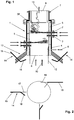
- shows schematically a smelting cyclone with oxygen injectors below the smelting cyclone;
- fig.2
- shows schematically a number of oxygen injectors positioned below the first opening of the smelting cyclone at the bottom side thereof;
- fig.3
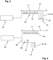
- shows a diagram of the oxygen supply system to the smelting cyclone,
- fig.4
- shows a diagram of another oxygen supply system to the smelting cyclone, and
- fig. 5
- shows schematically a smelting cyclone coupled to a metallurgical vessel for the production of molten iron.
- In
fig. 1 a smelting cyclone 1 is shown schematically with iron ore supply means in the form of a number ofiron ore injectors 2 and oxygen supply means in the form of a number ofoxygen injectors 3. The number of such injectors will depend on the size of the smelting cyclone but will in any way be more than the number of injectors shown in this figure. These injectors are positioned such that the oxygen and the iron ore are injected with tangential component as much as possible to generate a vortex or swirling motion inside the smelting cyclone. - The smelting cyclone 1 comprises an
outer wall 4 against the inside of which a number of water cooledsegments 5 are mounted. These water cooledsegments 5 have a coolingwater inlet 6 and coolingwater outlet 7. The smelting cyclone 1 has a cylindrical shape with a circular cross section with afirst opening 8 at the bottom side and asecond opening 9 at the top side. Instead of the cylindrical shape shown in the figure the smelting cyclone can also have a prismatic shape, for instance a right rectangular prismatic shape. In this example thesecond opening 9 has a smaller diameter than thefirst opening 8 because of acollar 36 at the top end of the melting zone, which is also the end of the water cooledsegments 5 in the smelting cyclone. - The
first opening 8 of the smelting cyclone is where a reducingprocess gas 10 enters the smelting cyclone. The partial combustion of the reducing process gas with the supplied oxygen generating the heat for melting the iron ore and the remaining part pre-reducing the iron ore. The resultingprocess gases 11 leave the smelting cyclone 1 through thesecond opening 9 which is connected to an exhaust system not further indicated in the drawing. Themolten iron oxides 12 flow or drip along the water cooledsegments 5 downward and drop from the last water cooledsegment 5 into a container, such as a metallurgical vessel, where the final reduction of the iron oxides will take place. Depending on the connection between the smelting cyclone and a metallurgical vessel the molten iron oxides may also flow from the smelting cyclone along the roof of the vessel and drip down the wall into the molten bath. Against the water cooled segments 5 a layer of iron oxides will accumulate which at the side facing away from thesegments 5 allows a temperature above the melting temperature of iron oxides. - The smelting cyclone 1 is connected to a cone shaped
wall 13 which may be the support of the smelting cyclone with which it can be mounted on a metallurgical vessel or it may be part of a metallurgical vessel to which the smelting cyclone is fixed. The cone shapedwall 13 will also have to be cooled if it is mounted to or part of a metallurgical vessel. - Although heat is generated in the smelting cyclone and in the metallurgical vessel to which the smelting cyclone will normally be fixed, the temperature at the
first opening 8 may get below the melting temperature of iron oxides. This may lead to solidification of the molten iron oxides and to accretions of solidified iron oxides. - Through the cone shaped
wall 13oxygen injectors 14 project. In the given example the oxygen injectors have afirst part 15 which project at about a straight angle through the cone shapedwall 13 and asecond part 16 at an angle to thefirst part 15. The oxygen injectors 14 are positioned such that the injected oxygen will contact the reducingprocess gas 10 in the region of thefirst opening 8 therewith preventing that the molten iron oxides can solidify at this point. - The oxygen injectors 14 are rotatable around the
first part 15 thereof resulting in that the direction of the injected oxygen can be varied. - In
fig. 2 a possible arrangement is indicated schematically. The oxygen injectors 14 are placed around and below the circumference of thefirst opening 8 of the smelting cyclone, which could be done with two opposite injectors, with three injectors at 120°, four injectors at 90° and so forth. For clarity's sake only twoinjectors 14 are shown in the drawing. - The oxygen injectors 14 can be rotated from a position where the oxygen is injected at an angle with respect to the
first opening 8 of smelting cyclone 1 without a tangential component, as indicated with thebroken line 17, to a position where the oxygen is injected in a more or less tangential direction with respect to thefirst opening 8 indicated with the position of thesecond part 16 of the injector. - A further example of an injector is indicated with 18 which comprises a straight part provided with a nozzle at or near an outer end of the injector which direct the oxygen leaving the injector at an angle. With the injector being rotatable it is possible to cover a wide area with the injected oxygen as indicated with the
broken lines 19. It is of course also possible to have a nozzle at the outer end ofinjector 18 and injecting the oxygen only in tangential direction. Such aninjector 18 does not need to be rotatable. - Preferably the
injectors first opening 8 of the smelting cyclone 1, that is that all oxygen is directed to the centre of thefirst opening 8 or away from said centre, for example with a tangential component or only in tangential direction. Moreover, the tangential component or tangential direction of the oxygen injected by each of theoxygen injectors -
Fig. 3 shows a diagram for the oxygen supply to theoxygen injectors 3 of the smelting cyclone 1 and thefurther oxygen injectors common duct 21 for afirst group 22 ofinjectors 3 and asecond group 23 ofinjectors injectors groups valve 24 by means of which the ratio between the oxygen supplied to the smelting cyclone 1 and the oxygen supplied to theinjectors - In
fig. 4 another configuration for the oxygen supply system is shown wherein the oxygen supply with control system schematically indicated with 20 is connected to aduct 21 for thefirst group 22 ofinjectors 3 and to aduct 25 for thesecond group 23 ofinjectors injectors 3 of thefirst group 22 are each provided with avalve 24 and theinjectors second group 23 now have in the duct a singleadjustable valve 26 and aflow meter 27. This configuration with flow measurement allows for an easier adjustment for bothgroups - Further configuration are possible such as a single valve and a flow meter also for the first group of
injectors 3 or a single valve and a flow meter for every so many injectors of the first group ofinjectors 3. - In yet another configuration, separate oxygen supply system could be provided for each
group group - Finally, separate oxygen supply systems could be provided for each individual injector in
group -
Fig. 5 shows an apparatus 30 consisting of a smelting cyclone 1 coupled to ametallurgical vessel 29 for the production of molten iron. An oxygen supply with control system, schematically indicated with 20, supplies oxygen to the smelting cyclone viaoxygen injectors 3, to themetallurgical vessel 29 vialances 28 and tooxygen injectors 14, which project through theroof 31 ofmetallurgical vessel 29 below thefirst opening 8 of the smelting cyclone 1. - The
metallurgical vessel 29 is provided with a lining 32 of refractory material at the lower part of the vessel. In this lowerpart liquid metal 33 accumulates with on top thereofliquid slag 34 during operation of the apparatus. Further, lances 35 are provided to inject coal and additives in theliquid slag 34. - A configuration such as shown in
fig. 5 allows for the injection of the total oxygen supplied to the apparatus distributed overoxygen injectors 3 in the smelting cyclone, theoxygen injectors 14 below thefirst opening 8 of the smelting cyclone and thelances 28, where the distribution is determined on basis of local heating requirements in the apparatus and/or requirements to the reduction potential of the process gas. Similar to the descriptions forfig 3. and fig. 4 , the oxygen supply to theinjectors lances 28 may be from a single oxygen supply withcontrol system 20, such as indicated infig. 5 , properly configured with valves and flow meters so to achieve the desired distribution among the injectors and lances. - Another configuration (not displayed in
fig. 5 ) foresees in having a dedicated oxygen supply with control system for theinjectors 3 present in smelting cyclone 1 and for theinjectors 14 at or near thefirst opening 8 of the smelting cyclone 1 and a dedicated oxygen supply with control system for thelances 28. - In yet another configuration (not displayed in
fig. 5 ), dedicated oxygen supply systems with control system are installed foroxygen injectors 3, foroxygen injectors 14 and forlances 28. - In still another configuration (not displayed in
fig. 5 ), dedicated oxygen supply systems with control system are installed for eachindividual injectors
Claims (11)
- Apparatus for the production of molten iron comprising a metallurgical vessel (29) and a smelting cyclone (1) for the production of pre-reduced molten iron oxides, wherein the smelting cyclone (1) is provided on the top part of the metallurgical vessel (29) and in open connection with the interior of the metallurgical vessel (29) and wherein the smelting cyclone (1) is provided with a first and second opening (8, 9), the first opening (8) serving as an inlet for reducing process gas and as an outlet for molten pre-reduced iron oxides and the second opening (9) serving as an outlet for process gas, with supply means (2) to supply iron ore into the smelting cyclone (1) and with oxygen supply means (3) to supply oxygen into the smelting cyclone (1), characterised in that additional heating means are provided to prevent solidification of molten iron oxides at or near the first opening (8) of the smelting cyclone (1), wherein the additional heating means comprise at least two oxygen injectors (14, 18) that in operation inject oxygen from a location below the first opening (8) of the smelting cyclone (1) in a direction such that the injected oxygen will come into contact with process gas entering the first opening (8) and wherein the at least two oxygen injectors (14, 18) are positioned outside the circumference of the first opening (8) as seen in vertical downward direction.
- Apparatus according to claim 1, wherein the oxygen injectors (14, 18) are arranged such that in operation the oxygen is injected in a direction which is at least partially in line with the direction of flow of process gas entering the smelting cyclone (1).
- Apparatus according to claim 1-2, wherein the oxygen injectors (14, 18) are arranged such that in operation combustion of the injected oxygen and part of the process gas takes place in the region of the first opening (8) of the smelting cyclone (1).
- Apparatus according to one or more of claims 1-3, wherein the oxygen injectors (14, 18) are adjustable such that the direction of injection of the oxygen can be adjusted.
- Apparatus according to one or more of claims 1-4, wherein the oxygen injectors (14, 18) are connected to the oxygen supply (20) for the supply means (3) to supply oxygen into the smelting cyclone (1).
- Apparatus according to claim 5, wherein the oxygen injectors (14, 18) and the supply means (3) to supply oxygen into the smelting cyclone (1) are separately adjustable.
- Apparatus according to claim 6, wherein the oxygen injectors (14, 18) are provided with common flow meter means (27) and common adjusting means (26) to adjust the total amount of injected oxygen.
- Apparatus according to one or more of claims 1-4, wherein the oxygen injectors (14, 18) are connected to an oxygen supply separate from the oxygen supply (20) for the supply means (3) to supply oxygen into the smelting cyclone (1).
- Apparatus according to one or more of claims 1-8, wherein the metallurgical vessel (29) has a bottom part with a refractory lining (32) for accommodating a molten iron bath (33) and a water cooled pressure resistant top part.
- Apparatus according to one or more of claims 1-9, wherein the metallurgical vessel (29) is provided with coal supply means (35) and further oxygen supply means (28) for the final reduction process of molten iron (33) in the bottom part of the metallurgical vessel (29).
- Apparatus according to one or more of claims 1-10, wherein oxygen supply means (3; 14, 18; 28) are provided for in at least three zones.
Priority Applications (2)
| Application Number | Priority Date | Filing Date | Title |
|---|---|---|---|
| PL12810104T PL2794931T3 (en) | 2011-12-19 | 2012-12-19 | Smelting cyclone and apparatus provided with such a smelting cyclone |
| EP12810104.5A EP2794931B1 (en) | 2011-12-19 | 2012-12-19 | Smelting cyclone and apparatus provided with such a smelting cyclone |
Applications Claiming Priority (3)
| Application Number | Priority Date | Filing Date | Title |
|---|---|---|---|
| EP11009940 | 2011-12-19 | ||
| EP12810104.5A EP2794931B1 (en) | 2011-12-19 | 2012-12-19 | Smelting cyclone and apparatus provided with such a smelting cyclone |
| PCT/EP2012/005258 WO2013091847A1 (en) | 2011-12-19 | 2012-12-19 | Smelting cyclone and apparatus provided with such a smelting cyclone |
Publications (2)
| Publication Number | Publication Date |
|---|---|
| EP2794931A1 EP2794931A1 (en) | 2014-10-29 |
| EP2794931B1 true EP2794931B1 (en) | 2018-10-17 |
Family
ID=47504820
Family Applications (1)
| Application Number | Title | Priority Date | Filing Date |
|---|---|---|---|
| EP12810104.5A Active EP2794931B1 (en) | 2011-12-19 | 2012-12-19 | Smelting cyclone and apparatus provided with such a smelting cyclone |
Country Status (4)
| Country | Link |
|---|---|
| EP (1) | EP2794931B1 (en) |
| CN (1) | CN104093861B (en) |
| PL (1) | PL2794931T3 (en) |
| WO (1) | WO2013091847A1 (en) |
Cited By (1)
| Publication number | Priority date | Publication date | Assignee | Title |
|---|---|---|---|---|
| WO2021105400A1 (en) | 2019-11-28 | 2021-06-03 | Tata Steel Ijmuiden B.V. | Apparatus for the production of molten iron |
Families Citing this family (5)
| Publication number | Priority date | Publication date | Assignee | Title |
|---|---|---|---|---|
| KR102369474B1 (en) * | 2013-12-19 | 2022-03-02 | 타타 스틸 네덜란드 테크날러지 베.뷔. | Method to operate a smelt cyclone |
| WO2018166776A1 (en) | 2017-03-17 | 2018-09-20 | Tata Steel Nederland Technology B.V. | Lance for a gas analysis system |
| US12018340B2 (en) * | 2018-03-30 | 2024-06-25 | Tata Steel Nederland Technology B.V. | Direct smelting process with full combustion |
| CN113088611B (en) * | 2021-03-23 | 2022-09-23 | 武汉科技大学 | A pure oxygen two-stage preheating reduction ironmaking process |
| CN114440635B (en) * | 2022-01-19 | 2023-09-12 | 安徽省瀚海新材料股份有限公司 | Smelting equipment is used in neodymium iron boron production |
Family Cites Families (8)
| Publication number | Priority date | Publication date | Assignee | Title |
|---|---|---|---|---|
| US3607224A (en) * | 1968-03-20 | 1971-09-21 | Combustion Eng | Direct reduction of iron ore |
| DK288176A (en) * | 1975-07-04 | 1977-01-05 | Boliden Ab | PROCEDURE FOR PREPARING A PARTLY PRE-REDUCED PRODUCT |
| NL9400936A (en) * | 1994-06-09 | 1996-01-02 | Hoogovens Groep Bv | Method for treating zinc-containing dust. |
| NL9401103A (en) * | 1994-07-01 | 1996-02-01 | Hoogovens Groep Bv | Method and device for the pre-reduction of iron compounds. |
| NL9500264A (en) | 1995-02-13 | 1996-09-02 | Hoogovens Staal Bv | Method for producing liquid pig iron. |
| NL9500600A (en) | 1995-03-29 | 1996-11-01 | Hoogovens Staal Bv | Device for producing liquid pig iron by direct reduction. |
| US6214084B1 (en) * | 1997-09-03 | 2001-04-10 | The Boc Group, Inc. | Iron manufacturing process |
| WO2004007777A2 (en) * | 2002-07-10 | 2004-01-22 | Corus Technology Bv | Metallurgical vessel and method of iron making by means of direct reduction |
-
2012
- 2012-12-19 EP EP12810104.5A patent/EP2794931B1/en active Active
- 2012-12-19 WO PCT/EP2012/005258 patent/WO2013091847A1/en not_active Ceased
- 2012-12-19 PL PL12810104T patent/PL2794931T3/en unknown
- 2012-12-19 CN CN201280068458.XA patent/CN104093861B/en active Active
Non-Patent Citations (1)
| Title |
|---|
| None * |
Cited By (2)
| Publication number | Priority date | Publication date | Assignee | Title |
|---|---|---|---|---|
| WO2021105400A1 (en) | 2019-11-28 | 2021-06-03 | Tata Steel Ijmuiden B.V. | Apparatus for the production of molten iron |
| US12595520B2 (en) | 2019-11-28 | 2026-04-07 | Tata Steel Ijmuiden B.V. | Apparatus for the production of molten iron |
Also Published As
| Publication number | Publication date |
|---|---|
| PL2794931T3 (en) | 2019-02-28 |
| WO2013091847A1 (en) | 2013-06-27 |
| CN104093861B (en) | 2016-09-21 |
| CN104093861A (en) | 2014-10-08 |
| EP2794931A1 (en) | 2014-10-29 |
Similar Documents
| Publication | Publication Date | Title |
|---|---|---|
| WO2013091847A1 (en) | Smelting cyclone and apparatus provided with such a smelting cyclone | |
| CA2642674C (en) | Direct smelting plant | |
| CN1144275A (en) | Apparatus for producing molten pig iron by direct reduction | |
| EP2834562B1 (en) | Fluidic control burner for pulverous feed | |
| EP4520461A1 (en) | Granular iron manufacturing device and granular iron manufacturing method | |
| US7473297B2 (en) | Vertical shaft melting furnace | |
| EP1930448B1 (en) | Shaft furnace | |
| CN1977055B (en) | Metallurgical processing equipment | |
| CN103687965B (en) | Melting and reducing equipment and the method for running melting and reducing equipment | |
| EP2379973B1 (en) | Bustle pipe arrangement | |
| CN109112320A (en) | A kind of bottom blowing copper smelting device supplied using air brick | |
| CN206607247U (en) | Gas-based reduction shaft furnace | |
| EP2208952A1 (en) | Bustle pipe arrangement | |
| KR100441791B1 (en) | Device and method for dosed introduction of fine particle material into a reactor vessel | |
| CN114807477B (en) | Blast furnace slag runner nozzle and slag discharging method | |
| CN110791606A (en) | Tuyere water spraying device | |
| UA121537C2 (en) | A solids injection lance | |
| EP0164878A2 (en) | Method of operating metallurgical furnace | |
| SU1127908A1 (en) | Tuyere for heating charge and blowing metal | |
| KR101060820B1 (en) | Reduction furnace with uniform gas flow distribution | |
| SU1067054A1 (en) | Tuyere for bottom blowing of metal | |
| JP2013521353A (en) | Water distribution system in gasification reactor | |
| WO2017195105A1 (en) | Lance for use in a top submerged lance furnace | |
| UA102317C2 (en) | tuyere for blowing the converter bath | |
| KR20160137197A (en) | Gimbal distributor for furnace |
Legal Events
| Date | Code | Title | Description |
|---|---|---|---|
| PUAI | Public reference made under article 153(3) epc to a published international application that has entered the european phase |
Free format text: ORIGINAL CODE: 0009012 |
|
| 17P | Request for examination filed |
Effective date: 20140721 |
|
| AK | Designated contracting states |
Kind code of ref document: A1 Designated state(s): AL AT BE BG CH CY CZ DE DK EE ES FI FR GB GR HR HU IE IS IT LI LT LU LV MC MK MT NL NO PL PT RO RS SE SI SK SM TR |
|
| DAX | Request for extension of the european patent (deleted) | ||
| 17Q | First examination report despatched |
Effective date: 20160915 |
|
| GRAP | Despatch of communication of intention to grant a patent |
Free format text: ORIGINAL CODE: EPIDOSNIGR1 |
|
| INTG | Intention to grant announced |
Effective date: 20180531 |
|
| GRAS | Grant fee paid |
Free format text: ORIGINAL CODE: EPIDOSNIGR3 |
|
| GRAA | (expected) grant |
Free format text: ORIGINAL CODE: 0009210 |
|
| AK | Designated contracting states |
Kind code of ref document: B1 Designated state(s): AL AT BE BG CH CY CZ DE DK EE ES FI FR GB GR HR HU IE IS IT LI LT LU LV MC MK MT NL NO PL PT RO RS SE SI SK SM TR |
|
| REG | Reference to a national code |
Ref country code: GB Ref legal event code: FG4D |
|
| REG | Reference to a national code |
Ref country code: CH Ref legal event code: EP |
|
| REG | Reference to a national code |
Ref country code: IE Ref legal event code: FG4D |
|
| REG | Reference to a national code |
Ref country code: DE Ref legal event code: R096 Ref document number: 602012052387 Country of ref document: DE Ref country code: AT Ref legal event code: REF Ref document number: 1054101 Country of ref document: AT Kind code of ref document: T Effective date: 20181115 |
|
| REG | Reference to a national code |
Ref country code: NL Ref legal event code: FP |
|
| REG | Reference to a national code |
Ref country code: SE Ref legal event code: TRGR |
|
| REG | Reference to a national code |
Ref country code: SK Ref legal event code: T3 Ref document number: E 29071 Country of ref document: SK |
|
| REG | Reference to a national code |
Ref country code: LT Ref legal event code: MG4D |
|
| PG25 | Lapsed in a contracting state [announced via postgrant information from national office to epo] |
Ref country code: IS Free format text: LAPSE BECAUSE OF FAILURE TO SUBMIT A TRANSLATION OF THE DESCRIPTION OR TO PAY THE FEE WITHIN THE PRESCRIBED TIME-LIMIT Effective date: 20190217 Ref country code: FI Free format text: LAPSE BECAUSE OF FAILURE TO SUBMIT A TRANSLATION OF THE DESCRIPTION OR TO PAY THE FEE WITHIN THE PRESCRIBED TIME-LIMIT Effective date: 20181017 Ref country code: BG Free format text: LAPSE BECAUSE OF FAILURE TO SUBMIT A TRANSLATION OF THE DESCRIPTION OR TO PAY THE FEE WITHIN THE PRESCRIBED TIME-LIMIT Effective date: 20190117 Ref country code: HR Free format text: LAPSE BECAUSE OF FAILURE TO SUBMIT A TRANSLATION OF THE DESCRIPTION OR TO PAY THE FEE WITHIN THE PRESCRIBED TIME-LIMIT Effective date: 20181017 Ref country code: LV Free format text: LAPSE BECAUSE OF FAILURE TO SUBMIT A TRANSLATION OF THE DESCRIPTION OR TO PAY THE FEE WITHIN THE PRESCRIBED TIME-LIMIT Effective date: 20181017 Ref country code: ES Free format text: LAPSE BECAUSE OF FAILURE TO SUBMIT A TRANSLATION OF THE DESCRIPTION OR TO PAY THE FEE WITHIN THE PRESCRIBED TIME-LIMIT Effective date: 20181017 Ref country code: LT Free format text: LAPSE BECAUSE OF FAILURE TO SUBMIT A TRANSLATION OF THE DESCRIPTION OR TO PAY THE FEE WITHIN THE PRESCRIBED TIME-LIMIT Effective date: 20181017 Ref country code: NO Free format text: LAPSE BECAUSE OF FAILURE TO SUBMIT A TRANSLATION OF THE DESCRIPTION OR TO PAY THE FEE WITHIN THE PRESCRIBED TIME-LIMIT Effective date: 20190117 |
|
| PG25 | Lapsed in a contracting state [announced via postgrant information from national office to epo] |
Ref country code: PT Free format text: LAPSE BECAUSE OF FAILURE TO SUBMIT A TRANSLATION OF THE DESCRIPTION OR TO PAY THE FEE WITHIN THE PRESCRIBED TIME-LIMIT Effective date: 20190217 Ref country code: RS Free format text: LAPSE BECAUSE OF FAILURE TO SUBMIT A TRANSLATION OF THE DESCRIPTION OR TO PAY THE FEE WITHIN THE PRESCRIBED TIME-LIMIT Effective date: 20181017 Ref country code: GR Free format text: LAPSE BECAUSE OF FAILURE TO SUBMIT A TRANSLATION OF THE DESCRIPTION OR TO PAY THE FEE WITHIN THE PRESCRIBED TIME-LIMIT Effective date: 20190118 Ref country code: AL Free format text: LAPSE BECAUSE OF FAILURE TO SUBMIT A TRANSLATION OF THE DESCRIPTION OR TO PAY THE FEE WITHIN THE PRESCRIBED TIME-LIMIT Effective date: 20181017 |
|
| REG | Reference to a national code |
Ref country code: DE Ref legal event code: R097 Ref document number: 602012052387 Country of ref document: DE |
|
| PG25 | Lapsed in a contracting state [announced via postgrant information from national office to epo] |
Ref country code: CZ Free format text: LAPSE BECAUSE OF FAILURE TO SUBMIT A TRANSLATION OF THE DESCRIPTION OR TO PAY THE FEE WITHIN THE PRESCRIBED TIME-LIMIT Effective date: 20181017 Ref country code: DK Free format text: LAPSE BECAUSE OF FAILURE TO SUBMIT A TRANSLATION OF THE DESCRIPTION OR TO PAY THE FEE WITHIN THE PRESCRIBED TIME-LIMIT Effective date: 20181017 |
|
| REG | Reference to a national code |
Ref country code: CH Ref legal event code: PL |
|
| PLBE | No opposition filed within time limit |
Free format text: ORIGINAL CODE: 0009261 |
|
| STAA | Information on the status of an ep patent application or granted ep patent |
Free format text: STATUS: NO OPPOSITION FILED WITHIN TIME LIMIT |
|
| PG25 | Lapsed in a contracting state [announced via postgrant information from national office to epo] |
Ref country code: MC Free format text: LAPSE BECAUSE OF FAILURE TO SUBMIT A TRANSLATION OF THE DESCRIPTION OR TO PAY THE FEE WITHIN THE PRESCRIBED TIME-LIMIT Effective date: 20181017 Ref country code: EE Free format text: LAPSE BECAUSE OF FAILURE TO SUBMIT A TRANSLATION OF THE DESCRIPTION OR TO PAY THE FEE WITHIN THE PRESCRIBED TIME-LIMIT Effective date: 20181017 Ref country code: SM Free format text: LAPSE BECAUSE OF FAILURE TO SUBMIT A TRANSLATION OF THE DESCRIPTION OR TO PAY THE FEE WITHIN THE PRESCRIBED TIME-LIMIT Effective date: 20181017 Ref country code: RO Free format text: LAPSE BECAUSE OF FAILURE TO SUBMIT A TRANSLATION OF THE DESCRIPTION OR TO PAY THE FEE WITHIN THE PRESCRIBED TIME-LIMIT Effective date: 20181017 Ref country code: LU Free format text: LAPSE BECAUSE OF NON-PAYMENT OF DUE FEES Effective date: 20181219 |
|
| REG | Reference to a national code |
Ref country code: IE Ref legal event code: MM4A |
|
| 26N | No opposition filed |
Effective date: 20190718 |
|
| PG25 | Lapsed in a contracting state [announced via postgrant information from national office to epo] |
Ref country code: IE Free format text: LAPSE BECAUSE OF NON-PAYMENT OF DUE FEES Effective date: 20181219 Ref country code: SI Free format text: LAPSE BECAUSE OF FAILURE TO SUBMIT A TRANSLATION OF THE DESCRIPTION OR TO PAY THE FEE WITHIN THE PRESCRIBED TIME-LIMIT Effective date: 20181017 |
|
| PG25 | Lapsed in a contracting state [announced via postgrant information from national office to epo] |
Ref country code: LI Free format text: LAPSE BECAUSE OF NON-PAYMENT OF DUE FEES Effective date: 20181231 Ref country code: CH Free format text: LAPSE BECAUSE OF NON-PAYMENT OF DUE FEES Effective date: 20181231 |
|
| PG25 | Lapsed in a contracting state [announced via postgrant information from national office to epo] |
Ref country code: MT Free format text: LAPSE BECAUSE OF NON-PAYMENT OF DUE FEES Effective date: 20181219 |
|
| PG25 | Lapsed in a contracting state [announced via postgrant information from national office to epo] |
Ref country code: TR Free format text: LAPSE BECAUSE OF FAILURE TO SUBMIT A TRANSLATION OF THE DESCRIPTION OR TO PAY THE FEE WITHIN THE PRESCRIBED TIME-LIMIT Effective date: 20181017 |
|
| PG25 | Lapsed in a contracting state [announced via postgrant information from national office to epo] |
Ref country code: CY Free format text: LAPSE BECAUSE OF FAILURE TO SUBMIT A TRANSLATION OF THE DESCRIPTION OR TO PAY THE FEE WITHIN THE PRESCRIBED TIME-LIMIT Effective date: 20181017 Ref country code: HU Free format text: LAPSE BECAUSE OF FAILURE TO SUBMIT A TRANSLATION OF THE DESCRIPTION OR TO PAY THE FEE WITHIN THE PRESCRIBED TIME-LIMIT; INVALID AB INITIO Effective date: 20121219 Ref country code: MK Free format text: LAPSE BECAUSE OF NON-PAYMENT OF DUE FEES Effective date: 20181017 |
|
| REG | Reference to a national code |
Ref country code: AT Ref legal event code: UEP Ref document number: 1054101 Country of ref document: AT Kind code of ref document: T Effective date: 20181017 |
|
| P01 | Opt-out of the competence of the unified patent court (upc) registered |
Effective date: 20230517 |
|
| PGFP | Annual fee paid to national office [announced via postgrant information from national office to epo] |
Ref country code: GB Payment date: 20251229 Year of fee payment: 14 |
|
| PGFP | Annual fee paid to national office [announced via postgrant information from national office to epo] |
Ref country code: AT Payment date: 20251230 Year of fee payment: 14 |
|
| PGFP | Annual fee paid to national office [announced via postgrant information from national office to epo] |
Ref country code: IT Payment date: 20251219 Year of fee payment: 14 |
|
| PGFP | Annual fee paid to national office [announced via postgrant information from national office to epo] |
Ref country code: NL Payment date: 20251226 Year of fee payment: 14 Ref country code: FR Payment date: 20251226 Year of fee payment: 14 |
|
| PGFP | Annual fee paid to national office [announced via postgrant information from national office to epo] |
Ref country code: BE Payment date: 20251229 Year of fee payment: 14 |
|
| PGFP | Annual fee paid to national office [announced via postgrant information from national office to epo] |
Ref country code: SE Payment date: 20251227 Year of fee payment: 14 |
|
| PGFP | Annual fee paid to national office [announced via postgrant information from national office to epo] |
Ref country code: PL Payment date: 20251202 Year of fee payment: 14 |
|
| PGFP | Annual fee paid to national office [announced via postgrant information from national office to epo] |
Ref country code: SK Payment date: 20251203 Year of fee payment: 14 |
|
| PGFP | Annual fee paid to national office [announced via postgrant information from national office to epo] |
Ref country code: DE Payment date: 20251229 Year of fee payment: 14 |