EP2794162B1 - Forward extending workpiece support - Google Patents
Forward extending workpiece support Download PDFInfo
- Publication number
- EP2794162B1 EP2794162B1 EP12816402.7A EP12816402A EP2794162B1 EP 2794162 B1 EP2794162 B1 EP 2794162B1 EP 12816402 A EP12816402 A EP 12816402A EP 2794162 B1 EP2794162 B1 EP 2794162B1
- Authority
- EP
- European Patent Office
- Prior art keywords
- base
- supplemental
- handle
- power saw
- support
- Prior art date
- Legal status (The legal status is an assumption and is not a legal conclusion. Google has not performed a legal analysis and makes no representation as to the accuracy of the status listed.)
- Active
Links
Images









Classifications
-
- B—PERFORMING OPERATIONS; TRANSPORTING
- B23—MACHINE TOOLS; METAL-WORKING NOT OTHERWISE PROVIDED FOR
- B23D—PLANING; SLOTTING; SHEARING; BROACHING; SAWING; FILING; SCRAPING; LIKE OPERATIONS FOR WORKING METAL BY REMOVING MATERIAL, NOT OTHERWISE PROVIDED FOR
- B23D47/00—Sawing machines or sawing devices working with circular saw blades, characterised only by constructional features of particular parts
- B23D47/02—Sawing machines or sawing devices working with circular saw blades, characterised only by constructional features of particular parts of frames; of guiding arrangements for work-table or saw-carrier
- B23D47/025—Sawing machines or sawing devices working with circular saw blades, characterised only by constructional features of particular parts of frames; of guiding arrangements for work-table or saw-carrier of tables
-
- Y—GENERAL TAGGING OF NEW TECHNOLOGICAL DEVELOPMENTS; GENERAL TAGGING OF CROSS-SECTIONAL TECHNOLOGIES SPANNING OVER SEVERAL SECTIONS OF THE IPC; TECHNICAL SUBJECTS COVERED BY FORMER USPC CROSS-REFERENCE ART COLLECTIONS [XRACs] AND DIGESTS
- Y10—TECHNICAL SUBJECTS COVERED BY FORMER USPC
- Y10T—TECHNICAL SUBJECTS COVERED BY FORMER US CLASSIFICATION
- Y10T83/00—Cutting
- Y10T83/889—Tool with either work holder or means to hold work supply
Definitions
- the present invention relates to a power saw arrangement according to the preamble of claim 1.
- An example of such a power saw arrangement can be seen in WO 2005/102626 A2 .
- FIG. 1a depicts a conventional power saw arrangement 100 including a base 102, a fence 120, a motor 122, a saw blade 124, a table 140 and a handle 160.
- the power saw arrangement 100 is that of a miter saw.
- a support surface 104 of the base 102 is used to support a workpiece thereon during a cutting operation.
- the fence 120 is coupled to the base 102 perpendicular to the support surface 104, and the workpiece abuts the fence 120 during the cutting operation.
- the table 140 is movably coupled to the base 102 such that it rotates about a table axis 142.
- the saw blade 124 is coupled to the table 140 and is configured to rotate with the table 140 as is well known in the art.
- the table 140 also includes a table surface 144 perpendicular to the table axis 142 and substantially coplanar with the support surface 104.
- the table 140 includes a saw blade opening 146 defined in the table surface 144.
- the saw blade opening 146 is configured to receive the saw blade 124, operated by the motor 122, during the cutting operation.
- the saw blade opening 146 is fixed with respect to the table 140 such that it rotates with the table 140.
- the saw blade opening 146 is aligned with the handle 160.
- the handle 160 is fixed to the table 140 and extends outwardly therefrom. Movement of the handle 160 about the table axis 142 results in rotation of the table 140 about the table axis 142.
- FIG. 1b illustrates a top view of the base of the basic power saw arrangement shown in FIG. 1a .
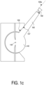
- FIGs. 1c and 1d illustrate top views of the basic power saw arrangement 100 shown in FIG. 1a including the table and the handle.
- the illustrations of the basic power saw arrangement in FIGs. 1b-1d do not include the motor or the saw blade.
- the base 102 includes the support surface 104, as well as a first wall 106 and a second wall 108 which are perpendicular to the support surface 104.
- the first wall 106 and second wall 108 are also provided in planes that are parallel to the table axis 142.
- the first wall 106 includes at least one point that acts as a first stop 107 which contacts the handle 160 as the handle 160 rotates with the table 140 in the direction of the first wall 106. As shown in FIG. 1c , upon contact with the first wall 106, the first stop 107 prevents the handle 160 from rotating any farther in the direction of the first wall 106.
- the second wall 108 includes at least one point that acts as a second stop 109 which contacts the handle 160 as the handle 160 rotates with the table 140 in the direction of the second wall 108. As shown in FIG. 1d , upon contact with the second wall 108, the second stop 109 prevents the handle 160 from rotating any farther in the direction of the second wall 108.
- first stop 107 and the second stop 109 may be provided in the form of planar surfaces or single points.
- the first stop 107 and the second stop 109 may be provided in the same or in different forms. In the exemplary embodiment shown in FIGs. 1b-1d , the first stop 107 and the second stop 109 are both provided in the form of planar surfaces.
- the term "handle space” refers to the space occupied by the handle 160, and the space directly above or below the handle (i.e., in the direction defined by axis 142) when the handle moves between the first stop 107 and the second stop 109.
- the "handle space” includes the space extending across the full range of motion of the handle 160.
- An illustration of the handle space 110 for the saw of FIGs. 1c and 1d is provided by the diagonal lines in FIG. 1b .
- the handle 160 includes a handle edge 162 positioned opposite the table 140.
- the handle 160 contacts the first stop 107, a point on the handle edge 162 and the first stop 107 define a first plane 106a that is parallel to the table axis 142.
- a point on the handle edge 162 and the second stop 109 define a second plane 108a that is parallel to the table axis 142.
- the "handle space" 110 for the exemplary saw of FIGs. 1c-1d is provided within the space between the first plane 106a and the second plane 108a, along an arc 143 defined by the outermost edge of the handle when the handle moves between the first stop 107 and the second stop 109.
- corresponding structures create corresponding "handle spaces" as defined above.
- FIG. 2 illustrates the base of a basic power saw arrangement 100 like that shown in FIGs. 1b-1d .
- the power saw arrangement 100 includes the table 140 and the handle 160 which projects from the table 140 into the handle space 110.
- the table 140 rotates about the table axis 142, the handle 160 moves within the handle space 110.
- the movement of the handle 160 within the handle space 110 is limited by contact with the first stop 107 and the second stop 109. Consequently, the rotation of the table 140 is limited by the movement of the handle 160 within the handle space 110.
- a user When performing a cutting operation, a user places the workpiece 10 (illustrated by dotted lines in FIG. 2 ) on the support surface 104 and the table surface 144 as shown.
- the workpiece 10 rests against the fence 120 to control the position and prevent movement of the workpiece 10 during the cutting operation.
- the workpiece 10 has a length 12 and a width 14.
- the angle of the handle 160, and thus the angle of the table 140, with respect to the base 102 determines the angle of the saw blade opening 146 which is configured to receive the saw blade. Therefore, when the saw blade opening 146 is aligned with the centerline 103 of the base 102, the saw blade will cut the workpiece at an angle of approximately 90 degrees.
- the table 140 can be rotated by rotating the handle 160 relative to the base 102 such that the saw blade opening 146 is no longer aligned with the centerline 103 of the base 102.
- the table 140 is also rotated relative to the base 102 such that the saw blade and the saw blade opening 146 are rotated relative to the base 102. Because this arrangement causes the saw blade opening 146 to be out of alignment with the centerline 103 of the base 102, the workpiece 10 is cut at an angle other than 90 degrees.
- the size of the workpiece 10 that can be accommodated by the power saw arrangement 100 is somewhat limited by the size of the base 102 and the position of the fence 120.
- the width 14 of the workpiece 10 is too great, the workpiece 10 will not be stably supported by the support surface 104 and the table surface 144 which may result in inconsistent cuts. Therefore, supplemental supports which extend into the handle space 110 accommodate workpieces 10 having greater widths 14.
- supplemental supports which extend into the handle space 110 limit the range of movement of the handle 160 within the handle space 110 and thus limit the angles at which workpieces 10 can be cut.
- US 2005/262985 A1 describes a miter saw with a saw blade and a workpiece stop, wherein the workpiece stop is selectively moveable to various positions for respective modes of operation.
- the miter saw also has a handle extending from a table of the miter saw, wherein said table and said handle are moveable and said handle engages the workpiece stop.
- the present invention provides a power saw arrangement including a saw blade with the features of claim 1.
- the power saw arrangements shown in FIGs. 4-18 are substantially similar to the power saw arrangement 100 of FIGs. 2-3 where the motor and saw blade are omitted for simplicity. However, as discussed below, the power saw arrangements shown in FIGs. 4-18 possess different structures.
- the power saw arrangement 200 shown in FIGs. 4-7 includes a base 202, a table 240 with a handle 260 extending into the handle space 210 and two supplemental supports 270 movably coupled to the base 202.
- the embodiment of the power saw arrangement 200 shown in FIGs. 4 and 6 includes two supplemental supports 270, but it is understood that the power saw arrangement 200 could alternatively include less than two or more than two supplemental supports 270.
- the first stop 207 and second stop 209, defining the handle space 210 are provided on the base 202 and are not provided on the supplemental supports 270.
- the base 202 includes base sides 212 that are opposite one another on either side of the centerline 203 and are fixed with respect to the base 202.
- a side axis 214 that is perpendicular to the table axis 242 and the centerline 203 extends through each base side 212.
- One supplemental support 270 is coupled to each base side 212 with a fastener 218.
- Each fastener 218 defines a fastener axis 215 that is orthogonal to the table axis 242 and the centerline 203.
- Each supplemental support 270 is configured to rotate about the fastener axis 215 at the fastener 218.
- the fastener 218 may be configured to possess any form which will rotatably couple the supplemental support 270 to the side base 212.
- the feature is configured in the form of a pin passing through the supplemental support 270 into the base 202 and a head projecting outwardly from the supplemental support 270 and retaining the supplemental support 270 on the pin.
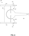
- the supplemental supports 270 are rotatable between an extended position (shown in FIGs. 4 and 5 ) and a retracted position (shown in FIGs. 6 and 7 ). When the supplemental supports 270 are in the extended position, they are extended into the handle space 210. When the supplemental supports 270 are in the retracted position, they are retracted out of the handle space 210.
- each supplemental support 270 includes a supplemental support surface 273, an extended notch 274 and a retracted notch 276.
- Each base side 212 includes a post 216 extending parallel to the fastener axis 215.
- the posts 216 are received within the extended notches 274 and the supplemental support surfaces 273 are substantially coplanar with the support surface 204 of the base 202 and the table surface 244 of the table 240.
- Workpieces are placed on the supplemental support surfaces 273 of the supplemental supports 270 when the supplemental supports 270 are in the extended position.
- the weight of a workpiece 10 on the supplemental support surface 273 creates a force shown by arrow F1.
- the force F1 causes the post 216 to remain within the extended notch 274.
- the supplemental supports 270 are rotatable about the fastener axes 215 at the fasteners 218 such that they no longer extend into the handle space 210.
- FIG. 7 when the supplemental supports 270 are in the retracted position, the posts 216 are received within the retracted notches 276. The force of gravity is shown by arrow F2 and causes the post 216 to remain within the retracted notch 276.
- the supplemental support 270 is provided substantially in the form of a rectangular parallelepiped, also known as a rectangular prism, and the supplemental support surface 273 is a planar surface thereof.
- the supplemental support 270 may be configured to possess any form which will provide support for workpieces that are wider than can be accommodated by the support surface 204 of the base 202 and the table surface 244 of the table 240.
- the supplemental support 270 could be provided in any form which enables it to rotate about the fastener axis 215 and receive the post 216 within the extended notch 274 such that the supplemental support 270 extends into the handle space 210 when in the extended position and receive the post 216 within the retracted notch 276 such that the supplemental support 270 does not extend into the handle space 210 when in the retracted position.
- the supplemental support 270 is provided in a form which enables it to support workpieces on its supplemental support surface 273.
- the supplemental support 270 may be provided substantially in the form of a cylinder including a supplemental support surface 273 in the form of a line on the outer surface of the cylinder rather than a plane on the outer surface of a rectangular parallelepiped.
- the power saw arrangement 200 shown in FIGs. 4-7 accommodates workpieces having larger widths than the power saw arrangement 100 shown in FIGs. 2-3 because the supplemental supports 270 in the power saw arrangement 200 provide additional support for workpiece width.
- a workpiece supported on the power saw arrangement 100 is supported by the support surface 104 and the table surface 144 but a workpiece supported on the power saw arrangement 200 is supported by the support surface 104, the table surface 144 and the supplemental support surface 273 of the supplemental support 270.
- the supplemental supports 270 of the power saw arrangement 200 are rotatable about the fastener axes 215 between an extended position and a retracted position, the supplemental supports 270 can be used to accommodate wider workpieces when in the extended position (shown in FIGs. 4 and 5 ) but do not extend into the handle space 110, and thus do not decrease the range of rotation of the handle 160 about the table axis 242, when in the retracted position (shown in FIGs. 6 and 7 ).
- the power saw arrangement 300 shown in FIGs. 8a-11 is not according to the invention and is present for illustration purposes only.
- the power saw arrangement 300 is formed with sliding side supports.
- the power saw arrangement 300 includes a base 302, a table 340 with a handle 360 extending into the handle space 310 and two supplemental supports 370 movably coupled to the base 302.
- the power saw arrangement 300 shown in FIGs. 8a and 10 includes two supplemental supports 370, but it is understood that the power saw arrangement 300 could alternatively include less than two or more than two supplemental supports 370.
- the first stop 307 and second stop 309, defining the handle space 310 are provided on the base 302 and are not provided on the supplemental supports 370.
- the base 302 includes base sides 312 that are opposite one another on either side of the centerline 303 of the base 302 and are fixed with respect to the base 302.
- a side axis 314 that is perpendicular to the table axis 342 and the centerline 303 extends through each base side 312.
- One supplemental support 370 is coupled to each base side 312 with fasteners 318 and is configured to slide relative to the base 302 in a direction perpendicular to the side axis 314 and parallel to the centerline 303.
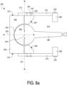
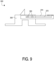
- the supplemental supports 370 are slidable relative to the support surface 304 between an extended position (shown in FIGs. 8a and 9 ) and a retracted position (shown in FIGs. 10 and 11 ). When the supplemental supports 370 are in the extended position, they are extended into the handle space 310. When the supplemental supports 370 are in the retracted position, they are retracted out of the handle space 310.
- each fastener 318 includes a post 322 and a head 324.
- the head 324 is sized larger than the post 322.
- Each fastener 318 is fixed in place on one of the base sides 312.
- each supplemental support 370 includes a slot 372 extending through the supplemental support 370.
- Each slot 372 is sized such that it is larger than the post 322 but smaller than the head 324 of the fastener 318.
- the post 322 of each fastener 318 extends through the slot 372, with the head 324 positioned outwardly from the slot 372.
- the supplemental supports 370 are thus perpendicularly slidable relative to the side axis 314 on the posts 322 and retained on the posts 322 by the heads 324.
- each supplemental support 370 includes a support portion 382.
- the support portion 382 is movably coupled to the supplemental support 370 by hinges 376.
- the hinges 376 enable the support portion 382 to rotate upwardly toward the support surface 304 of the base 302 or outwardly away from the centerline 303 of the base 302.
- the support portions 382 are substantially coplanar with the support surface 304 of the base 302 and the table surface 344 of the table 340.
- FIGs. 8a and 9 when the supplemental supports 370 are in the extended position, the support portions 382 are rotated inwardly to provide support for a workpiece.
- FIGs. 10 and 11 when the supplemental supports 370 are in the retracted position, the support portions 382 are rotated outwardly so that the support portions 382 do not contact the base 302 and the supplemental supports 370 can be fully removed from the handle space 310.
- the support portions 382 could also be provided in any form which is movably coupled to the supplemental supports 370 such that the support portions 382 are substantially coplanar with the support surface 304 of the base 302 and the table surface 344 of the table when in the extended position and do not contact the base 302 such that they can be completely removed from the handle space 310 when in the retracted position.
- the supplemental supports 370 of the power saw arrangement 300 are perpendicularly slidable relative to the side axes 314, and because the support portions 382 are hingedly coupled to the supplemental supports 370, the supplemental supports 370 can be moved between an extended position and a retracted position.
- the supplemental supports 370 can be used to accommodate wider workpieces when in the extended position (shown in FIGs. 8a and 9 ) but do not extend into the handle space 310, and thus do not decrease the range of rotation of the handle 360 about the table axis 342, when in the retracted position (shown in FIGs. 10 and 11 ).
- the supplemental supports 370 may not include hinges 376 shown in FIGs. 8a and 9-11 .
- the supplemental portions 382 are otherwise sized and shaped such that they are fully removed from the handle space 310 when the supplemental supports 370 are in the retracted position.
- the supplemental portions 382 may extend outwardly from the supplemental supports 370 away from the centerline 303.
- the supplemental portions 382 may have a triangular shape that allows the supplemental supports 370 to be fully removed from the handle space 310 when the supplemental supports 370 are in the retracted position with the triangularly shaped supplemental portions 382 abutting the support surface 304 on the base 302.
- a power saw arrangement 400 with a horizontally rotatable support is disclosed.
- the power saw arrangement 400 includes a base 402, a table 440 with a handle 460 extending into the handle space 410 and two supplemental supports 470 movably coupled to the base 402.
- the embodiment of the power saw arrangement 400 shown in FIGs. 12 and 13 includes two supplemental supports 470, but it is understood that the power saw arrangement 400 could alternatively include less than two or more than two supplemental supports 470.
- the first stop 407 and second stop 409, defining the handle space 410 are provided on the base 402 and are not provided on the supplemental supports 470.
- the base 402 includes base sides 412 that are opposite one another on either side of the centerline 403 and are fixed with respect to the base 402.
- Each base side 412 includes a side axis 414 that is perpendicular to the table axis 442 of the table 440 and perpendicular to the centerline 403 of the base 402.
- the base 402 includes lateral portions 422 that are opposite one another on either side of the centerline 403 and are fixed with respect to the base 402.
- One supplemental support 470 is coupled to each lateral portion 422 with a fastener 418 and is configured to rotate perpendicularly relative to the side axis 414 about the fastener 418.
- the supplemental supports 470 are rotatable between an extended position (shown in FIG. 13 ) and a retracted position (shown in FIG. 12 ).
- each lateral portion 422 includes a recess 424 sized and configured to retain the supplemental support 470.
- the supplemental supports 470 are received in the recesses 424 when in the retracted configuration (shown in FIG. 12 ) such that the supplemental supports 470 are completely removed from the handle space 410.
- the supplemental supports 470 When the supplemental supports 470 are in the extended position, they are rotated out of the recesses 424 and extended into the handle space 410 such that they are substantially coplanar with the support surface 404 of the base 402 and the table surface 444 of the table 440. When the supplemental supports 470 are in the retracted position, they are retracted out of the handle space 410 into the recesses 424 and remain substantially coplanar with the support surface 404 of the base 402 and the table surface 444 of the table 440.
- the supplemental supports 470 of the power saw arrangement 400 are perpendicularly rotatable relative to the side axes 414 and are rotatably coupled to the lateral portions 422, the supplemental supports 470 can be moved between an extended position and a retracted position.
- the supplemental supports 470 can be used to accommodate wider workpieces when in the extended position (shown in FIG. 13 ) but do not extend into the handle space 410, and thus do not decrease the range of rotation of the handle 460 about the table axis 442, when in the retracted position (shown in FIG. 12 ).
- the power saw arrangement 500 shown in FIGs. 14 and 15 is not according to the invention and is present for illustration purposes only.
- the power saw arrangement 500 is formed with front sliding supports.
- the power saw arrangement 500 includes a base 502, a table 540 with a handle 560 extending into the handle space 510 and two supplemental supports 570 movably coupled to the base 502.
- the power saw arrangement 500 shown in FIG. 14 includes two supplemental supports 570, but it is understood that the power saw arrangement 500 could alternatively include less than two or more than two supplemental supports 570.
- the first stop 507 and second stop 509, defining the handle space 510 are provided on the base 502 and are not provided on the supplemental supports 570.
- the base 502 includes base sides 512 that are opposite one another on either side of the centerline 503 and are fixed with respect to the base 502.
- a side axis 514 that is perpendicular to the table axis 542 and the centerline 503 extends from each base side 512.
- the base 502 includes lateral portions 522 that are opposite one another on either side of the centerline 503 and are fixed with respect to the base 502.
- Each lateral portion 522 includes channels 524 sized and configured to retain the supplemental support 570.
- the channels 524 are aligned perpendicularly relative to the table axis 542, perpendicularly relative to the side axis 514 and in parallel relative to the centerline 503.
- the supplemental supports 570 are received in the channels 524 when in the extended configuration (shown in FIGs. 14 and 15 ) such that the supplemental supports 570 extend into the handle space 510.
- the supplemental supports 570 are removed from the channels 524 when in the retracted position (not shown) such that they are fully removed from the handle space 510.
- Each supplemental support 570 consists of two arms 580 and a support portion 582 coupled to the arms 580.
- the arms 580 are inserted into the channels 524 and the supplemental supports 570 extend into the handle space 510 such that the support portions 582 are substantially coplanar with the support surface 504 of the base 502 and the table surface 544 of the table 540.
- the arms 580 are removed from the channels 524 and the supplemental supports 570 are removed from the handle space 510.
- the supplemental supports 570 are provided in the form of arms 580 and support portions 582 such that the supplemental supports 570 are in the retracted position when the arms 580 are removed from the channels 524.
- the supplemental supports 570 could be provided in any form which enables the supplemental supports 570 to extend into the handle space 510 such that the support portions 582 are substantially coplanar with the support surface 504 and the table surface 544 when in the extended position and enables the supplemental supports 570 to be removed from the handle space 510 when in the retracted position.
- the supplemental supports 570 could be configured such that they are inserted farther into longer channels 524 and do not extend into the handle space 510 when in the retracted position.
- the supplemental supports 570 of the power saw arrangement 500 are removably inserted into the lateral portions 522 perpendicularly relative to the side axes 514, the supplemental supports 570 can be moved between an extended position and a retracted position.
- the supplemental supports 570 can be used to accommodate wider workpieces when in the extended position (shown in FIG. 14 ) but do not extend into the handle space 510, and thus do not decrease the range of rotation of the handle 560 about the table axis 542, when in the retracted position (not shown).
- the power saw arrangement 600 shown in FIGs. 16-18 is not according to the invention and is present for illustration purposes only.
- the power saw arrangement 600 is formed with a top sliding support.
- the power saw arrangement 600 includes a base 602, a table 640 with a handle 660 extending into the handle space 610 and two supplemental supports 670 movably coupled to the base 602.
- the power saw arrangement 600 shown in FIGs. 16 and 17 includes two supplemental supports 670, but it is understood that the power saw arrangement 600 could alternatively include less than two or more than two supplemental supports 670.
- the first stop 607 and second stop 609, defining the handle space 610 are provided on the base 602 and are not provided on the supplemental supports 670.
- the base 602 includes base sides 612 that are opposite one another on either side of the centerline 603 and are fixed with respect to the base 602.
- Each base side 612 includes a side axis 614 that is perpendicular to the table axis 642 of the table 640 and perpendicular to the centerline 603 of the base 602.
- the base 602 includes lateral portions 622 that are opposite one another on either side of the centerline 603 and are fixed with respect to the base 602.
- Each lateral portion 622 includes recesses 624 sized and configured to retain the supplemental support 670.
- the recesses 624 are aligned perpendicularly relative to the table axis 642, perpendicularly relative to the side axis 614 and in parallel with the centerline 603.
- the supplemental supports 670 are slidable with respect to the base 602 between the extended position and the retracted position.
- the supplemental supports 670 are extended out of the recesses 624 when in the extended position (shown in FIG. 16 ) such that they extend into the handle space 610.
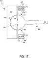
- the supplemental supports 670 are received in the recesses 624 when in the retracted position (shown in FIG. 17 ) such that the supplemental supports 670 are completely removed from the handle space 610.
- the supplemental supports 670 are coplanar with the table surface 644 of the table 640 and the support surface 604 of the base 602 when in the retracted position and in the extended position.
- the supplemental supports 670 include slots 672 extending through the supplemental supports 670 in a direction parallel with the table axis 642.
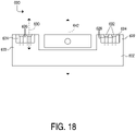
- FIG. 18 does not include the supplemental supports 670.
- the base 602 includes recesses 624 in the lateral portions 622.
- Each recess 624 includes mount members 626.
- Each mount member 626 consists of a post 628 and a head 632.
- the post 628 is fixed with respect to the recess 624.
- the post 628 extends along a post axis 630 which is parallel to the table axis 642 and is perpendicular to the slot 672 in the supplemental support 670.
- the post 62 is dimensioned such that it fits within a slot 672 in a supplemental support 670 (shown in FIGs. 16-17 ).
- the head 632 is coupled to the post 628 and sized larger than the post 628.
- the head 632 is dimensioned such that it is larger than, and does not fit within, the slot 672 in the supplemental support 670.
- the mount members 626 are configured such that the posts 628 extend through the slots 672 in the supplemental supports 670 and the supplemental supports 670 are retained on the posts 628 by the head 632.
- each recess 624 includes two mount members 626 and each supplemental support 670 includes two corresponding slots 672.
- each recess 624 may also include more or fewer than two mount members 626 and each supplemental support 670 includes a corresponding number of slots 672.
- the recesses 624 are provided on the lateral portions 622 of the base 602 and the post axes 630 extend perpendicularly to the side axes 614 and in parallel with the table axis 642. Furthermore, the recesses 624 may be provided on the base sides 612 of the base 602 and the post axes 630 may extend in parallel with the side axes 614 and perpendicularly to the table axis 642.
- the supplemental supports 670 of the power saw arrangement 600 are perpendicularly slidable into and out of recesses 624 in the lateral portions 622 of the base 602 and remain coplanar with the table surface 644 and the support surface 604 , the supplemental supports 670 can be moved between an extended position and a retracted position.
- the supplemental supports 670 can be used to accommodate wider workpieces when in the extended position (shown in FIG. 16 ) but do not extend into the handle space 610, and thus do not decrease the range of rotation of the handle 660 about the table axis 642, when in the retracted position (shown in FIG. 17 ).
Landscapes
- Engineering & Computer Science (AREA)
- Mechanical Engineering (AREA)
- Sawing (AREA)
Description
- The present invention relates to a power saw arrangement according to the preamble of
claim 1. An example of such a power saw arrangement can be seen inWO 2005/102626 A2 . -
FIG. 1a depicts a conventionalpower saw arrangement 100 including abase 102, afence 120, amotor 122, asaw blade 124, a table 140 and ahandle 160. In this example, thepower saw arrangement 100 is that of a miter saw. Asupport surface 104 of thebase 102 is used to support a workpiece thereon during a cutting operation. Thefence 120 is coupled to thebase 102 perpendicular to thesupport surface 104, and the workpiece abuts thefence 120 during the cutting operation. The table 140 is movably coupled to thebase 102 such that it rotates about atable axis 142. Thesaw blade 124 is coupled to the table 140 and is configured to rotate with the table 140 as is well known in the art. The table 140 also includes atable surface 144 perpendicular to thetable axis 142 and substantially coplanar with thesupport surface 104. The table 140 includes a saw blade opening 146 defined in thetable surface 144. Thesaw blade opening 146 is configured to receive thesaw blade 124, operated by themotor 122, during the cutting operation. Thesaw blade opening 146 is fixed with respect to the table 140 such that it rotates with the table 140. Thesaw blade opening 146 is aligned with thehandle 160. Thehandle 160 is fixed to the table 140 and extends outwardly therefrom. Movement of thehandle 160 about thetable axis 142 results in rotation of the table 140 about thetable axis 142. -
FIG. 1b illustrates a top view of the base of the basic power saw arrangement shown inFIG. 1a .FIGs. 1c and1d illustrate top views of the basicpower saw arrangement 100 shown inFIG. 1a including the table and the handle. For simplicity, the illustrations of the basic power saw arrangement inFIGs. 1b-1d do not include the motor or the saw blade. As shown inFIG. 1b , thebase 102 includes thesupport surface 104, as well as afirst wall 106 and asecond wall 108 which are perpendicular to thesupport surface 104. Referring toFIGs. 1c and1d , thefirst wall 106 andsecond wall 108 are also provided in planes that are parallel to thetable axis 142. Thefirst wall 106 includes at least one point that acts as afirst stop 107 which contacts thehandle 160 as thehandle 160 rotates with the table 140 in the direction of thefirst wall 106. As shown inFIG. 1c , upon contact with thefirst wall 106, thefirst stop 107 prevents thehandle 160 from rotating any farther in the direction of thefirst wall 106. Thesecond wall 108 includes at least one point that acts as asecond stop 109 which contacts thehandle 160 as thehandle 160 rotates with the table 140 in the direction of thesecond wall 108. As shown inFIG. 1d , upon contact with thesecond wall 108, thesecond stop 109 prevents thehandle 160 from rotating any farther in the direction of thesecond wall 108. It will be recognized that thefirst stop 107 and thesecond stop 109 may be provided in the form of planar surfaces or single points. Thefirst stop 107 and thesecond stop 109 may be provided in the same or in different forms. In the exemplary embodiment shown inFIGs. 1b-1d , thefirst stop 107 and thesecond stop 109 are both provided in the form of planar surfaces. - As used herein, the term "handle space" refers to the space occupied by the
handle 160, and the space directly above or below the handle (i.e., in the direction defined by axis 142) when the handle moves between thefirst stop 107 and thesecond stop 109. Thus, the "handle space" includes the space extending across the full range of motion of thehandle 160. An illustration of thehandle space 110 for the saw ofFIGs. 1c and1d is provided by the diagonal lines inFIG. 1b . As shown inFIGs. 1c and1d , thehandle 160 includes ahandle edge 162 positioned opposite the table 140. When thehandle 160 contacts thefirst stop 107, a point on thehandle edge 162 and thefirst stop 107 define afirst plane 106a that is parallel to thetable axis 142. When thehandle 160 contacts thesecond stop 109, a point on thehandle edge 162 and thesecond stop 109 define asecond plane 108a that is parallel to thetable axis 142. Thus, the "handle space" 110 for the exemplary saw ofFIGs. 1c-1d is provided within the space between thefirst plane 106a and thesecond plane 108a, along anarc 143 defined by the outermost edge of the handle when the handle moves between thefirst stop 107 and thesecond stop 109. In various power saws, corresponding structures create corresponding "handle spaces" as defined above. -
FIG. 2 illustrates the base of a basicpower saw arrangement 100 like that shown inFIGs. 1b-1d . Thepower saw arrangement 100 includes the table 140 and thehandle 160 which projects from the table 140 into thehandle space 110. When the table 140 rotates about thetable axis 142, thehandle 160 moves within thehandle space 110. The movement of thehandle 160 within thehandle space 110 is limited by contact with thefirst stop 107 and thesecond stop 109. Consequently, the rotation of the table 140 is limited by the movement of thehandle 160 within thehandle space 110. - When performing a cutting operation, a user places the workpiece 10 (illustrated by dotted lines in
FIG. 2 ) on thesupport surface 104 and thetable surface 144 as shown. Theworkpiece 10 rests against thefence 120 to control the position and prevent movement of theworkpiece 10 during the cutting operation. Theworkpiece 10 has alength 12 and awidth 14. The angle of thehandle 160, and thus the angle of the table 140, with respect to thebase 102, determines the angle of thesaw blade opening 146 which is configured to receive the saw blade. Therefore, when the saw blade opening 146 is aligned with thecenterline 103 of thebase 102, the saw blade will cut the workpiece at an angle of approximately 90 degrees. - As shown in
FIG. 3 , the table 140 can be rotated by rotating thehandle 160 relative to thebase 102 such that the saw blade opening 146 is no longer aligned with thecenterline 103 of thebase 102. When thehandle 160 is rotated relative to thebase 102, the table 140 is also rotated relative to thebase 102 such that the saw blade and thesaw blade opening 146 are rotated relative to thebase 102. Because this arrangement causes thesaw blade opening 146 to be out of alignment with thecenterline 103 of thebase 102, theworkpiece 10 is cut at an angle other than 90 degrees. - As illustrated by
FIGs. 2 and3 , the size of theworkpiece 10 that can be accommodated by thepower saw arrangement 100 is somewhat limited by the size of thebase 102 and the position of thefence 120. In particular, if thewidth 14 of theworkpiece 10 is too great, theworkpiece 10 will not be stably supported by thesupport surface 104 and thetable surface 144 which may result in inconsistent cuts. Therefore, supplemental supports which extend into thehandle space 110 accommodateworkpieces 10 havinggreater widths 14. However, supplemental supports which extend into thehandle space 110 limit the range of movement of thehandle 160 within thehandle space 110 and thus limit the angles at which workpieces 10 can be cut. In view of the foregoing, it would be advantageous to provide an improved power saw arrangement including supplemental supports accommodating workpieces having greater widths. It would be further advantageous if the supplemental supports did not extend into the handle space unless necessary for wider workpieces so that the range of angles for rotation of the table would not be unnecessarily reduced. -
US 2005/262985 A1 describes a miter saw with a saw blade and a workpiece stop, wherein the workpiece stop is selectively moveable to various positions for respective modes of operation. The miter saw also has a handle extending from a table of the miter saw, wherein said table and said handle are moveable and said handle engages the workpiece stop. - Further examples of power saw arrangements are disclosed by
WO 2005/102626 A2 ,US 5 819 623 A ,US 4 875 399 A andDE 195 08 044 A1 . - The present invention provides a power saw arrangement including a saw blade with the features of
claim 1. - The above described features and advantages, as well as others, will become more readily apparent to those of ordinary skill in the art by reference to the following detailed description and accompanying drawings.
-
-
FIG. 1a depicts a conventional power saw arrangement; -
FIG. 1b depicts a top view of the base of the basic power saw arrangement shown inFIG. 1a ; -
FIGs. 1c and1d depict top views of the basic power saw arrangement shown inFIG. 1a ; -
FIG. 2 depicts a top view of the power saw arrangement shown inFIG. 1a and a workpiece; -
FIG. 3 depicts a top view of the power saw arrangement shown inFIG. 2 with the table rotated relative to the base and a workpiece; -
FIG. 4 depicts a top view of one embodiment of a power saw arrangement according to the present invention including supplemental supports in an extended position; -
FIG. 5 depicts a side view of the power saw arrangement ofFIG. 4 including supplemental supports in an extended position; -
FIG. 6 depicts a top view of the power saw arrangement ofFIG. 4 including supplemental supports in a retracted position; -
FIG. 7 depicts a side view of the power saw arrangement ofFig. 4 including supplemental supports in a retracted position; -
FIG. 8a depicts a top view a power saw arrangement including supplemental supports in an extended position, which is not comprised by the present invention; -
FIG. 8b depicts an alternative embodiment of the power saw arrangement ofFIG. 8 ; -
FIG. 9 depicts a side view of the power saw arrangement ofFIG. 8a including supplemental supports in an extended position; -
FIG. 10 depicts a top view of the power saw arrangement ofFIG. 8a including supplemental supports in a retracted position; -
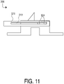
FIG. 11 depicts a side view of the power saw arrangement ofFIG. 8a including supplemental supports in a retracted position; -
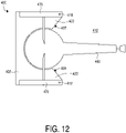
FIG. 12 depicts a top view of another embodiment of a power saw arrangement according to the present invention including supplemental supports in a retracted position; -
FIG. 13 depicts a top view of the power saw arrangement ofFIG. 12 including supplemental supports in an extended position; -
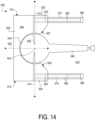
FIG. 14 depicts a top view of power saw arrangement including supplemental supports in an extended position, which is not comprised by the present invention; -
FIG. 15 depicts a side view of the power saw arrangement ofFIG. 14 including supplemental supports in an extended position; -
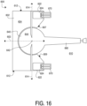
FIG. 16 depicts a top view of a power saw arrangement including supplemental supports in an extended position, which is not comprised by the present invention; -
FIG. 17 depicts a top view of the power saw arrangement ofFIG. 16 including supplemental supports in a retracted position; and -
FIG. 18 depicts a front view of the power saw arrangement ofFIG. 16 excluding supplemental supports. - The power saw arrangements shown in
FIGs. 4-18 are substantially similar to thepower saw arrangement 100 ofFIGs. 2-3 where the motor and saw blade are omitted for simplicity. However, as discussed below, the power saw arrangements shown inFIGs. 4-18 possess different structures. - The power saw
arrangement 200 shown inFIGs. 4-7 includes abase 202, a table 240 with a handle 260 extending into thehandle space 210 and twosupplemental supports 270 movably coupled to thebase 202. The embodiment of thepower saw arrangement 200 shown inFIGs. 4 and6 includes twosupplemental supports 270, but it is understood that thepower saw arrangement 200 could alternatively include less than two or more than twosupplemental supports 270. Note that thefirst stop 207 andsecond stop 209, defining thehandle space 210, are provided on thebase 202 and are not provided on the supplemental supports 270. - As shown in
FIG. 4 , thebase 202 includes base sides 212 that are opposite one another on either side of thecenterline 203 and are fixed with respect to thebase 202. Aside axis 214 that is perpendicular to thetable axis 242 and thecenterline 203 extends through eachbase side 212. Onesupplemental support 270 is coupled to eachbase side 212 with afastener 218. Eachfastener 218 defines afastener axis 215 that is orthogonal to thetable axis 242 and thecenterline 203. Eachsupplemental support 270 is configured to rotate about thefastener axis 215 at thefastener 218. Thefastener 218 may be configured to possess any form which will rotatably couple thesupplemental support 270 to theside base 212. For example, in this embodiment, the feature is configured in the form of a pin passing through thesupplemental support 270 into thebase 202 and a head projecting outwardly from thesupplemental support 270 and retaining thesupplemental support 270 on the pin. The supplemental supports 270 are rotatable between an extended position (shown inFIGs. 4 and5 ) and a retracted position (shown inFIGs. 6 and7 ). When thesupplemental supports 270 are in the extended position, they are extended into thehandle space 210. When thesupplemental supports 270 are in the retracted position, they are retracted out of thehandle space 210. - As shown in
FIG. 4 , eachsupplemental support 270 includes asupplemental support surface 273, anextended notch 274 and a retractednotch 276. Eachbase side 212 includes apost 216 extending parallel to thefastener axis 215. When thesupplemental supports 270 are in the extended position, theposts 216 are received within theextended notches 274 and the supplemental support surfaces 273 are substantially coplanar with thesupport surface 204 of thebase 202 and thetable surface 244 of the table 240. Workpieces are placed on the supplemental support surfaces 273 of thesupplemental supports 270 when thesupplemental supports 270 are in the extended position. As shown more clearly inFIG. 5 , the weight of aworkpiece 10 on thesupplemental support surface 273 creates a force shown by arrow F1. The force F1 causes thepost 216 to remain within theextended notch 274. - As shown in
FIG. 6 , thesupplemental supports 270 are rotatable about the fastener axes 215 at thefasteners 218 such that they no longer extend into thehandle space 210. As shown inFIG. 7 , when thesupplemental supports 270 are in the retracted position, theposts 216 are received within the retractednotches 276. The force of gravity is shown by arrow F2 and causes thepost 216 to remain within the retractednotch 276. - In the embodiment shown in
FIGs. 4-7 , thesupplemental support 270 is provided substantially in the form of a rectangular parallelepiped, also known as a rectangular prism, and thesupplemental support surface 273 is a planar surface thereof. However, thesupplemental support 270 may be configured to possess any form which will provide support for workpieces that are wider than can be accommodated by thesupport surface 204 of thebase 202 and thetable surface 244 of the table 240. Thesupplemental support 270 could be provided in any form which enables it to rotate about thefastener axis 215 and receive thepost 216 within theextended notch 274 such that thesupplemental support 270 extends into thehandle space 210 when in the extended position and receive thepost 216 within the retractednotch 276 such that thesupplemental support 270 does not extend into thehandle space 210 when in the retracted position. Thesupplemental support 270 is provided in a form which enables it to support workpieces on itssupplemental support surface 273. For example, thesupplemental support 270 may be provided substantially in the form of a cylinder including asupplemental support surface 273 in the form of a line on the outer surface of the cylinder rather than a plane on the outer surface of a rectangular parallelepiped. - The power saw
arrangement 200 shown inFIGs. 4-7 accommodates workpieces having larger widths than thepower saw arrangement 100 shown inFIGs. 2-3 because thesupplemental supports 270 in thepower saw arrangement 200 provide additional support for workpiece width. A workpiece supported on thepower saw arrangement 100 is supported by thesupport surface 104 and thetable surface 144 but a workpiece supported on thepower saw arrangement 200 is supported by thesupport surface 104, thetable surface 144 and thesupplemental support surface 273 of thesupplemental support 270. - Because the
supplemental supports 270 of thepower saw arrangement 200 are rotatable about the fastener axes 215 between an extended position and a retracted position, thesupplemental supports 270 can be used to accommodate wider workpieces when in the extended position (shown inFIGs. 4 and5 ) but do not extend into thehandle space 110, and thus do not decrease the range of rotation of thehandle 160 about thetable axis 242, when in the retracted position (shown inFIGs. 6 and7 ). - The power saw
arrangement 300 shown inFIGs. 8a-11 is not according to the invention and is present for illustration purposes only. The power sawarrangement 300 is formed with sliding side supports. The power sawarrangement 300 includes abase 302, a table 340 with ahandle 360 extending into thehandle space 310 and twosupplemental supports 370 movably coupled to thebase 302. The power sawarrangement 300 shown inFIGs. 8a and10 includes twosupplemental supports 370, but it is understood that thepower saw arrangement 300 could alternatively include less than two or more than twosupplemental supports 370. Note that thefirst stop 307 andsecond stop 309, defining thehandle space 310, are provided on thebase 302 and are not provided on the supplemental supports 370. - As shown in
FIG. 8a , thebase 302 includes base sides 312 that are opposite one another on either side of thecenterline 303 of thebase 302 and are fixed with respect to thebase 302. Aside axis 314 that is perpendicular to thetable axis 342 and thecenterline 303 extends through eachbase side 312. Onesupplemental support 370 is coupled to eachbase side 312 withfasteners 318 and is configured to slide relative to the base 302 in a direction perpendicular to theside axis 314 and parallel to thecenterline 303. The supplemental supports 370 are slidable relative to thesupport surface 304 between an extended position (shown inFIGs. 8a and9 ) and a retracted position (shown inFIGs. 10 and11 ). When thesupplemental supports 370 are in the extended position, they are extended into thehandle space 310. When thesupplemental supports 370 are in the retracted position, they are retracted out of thehandle space 310. - As shown in
FIGs. 8a and10 , eachfastener 318 includes apost 322 and ahead 324. Thehead 324 is sized larger than thepost 322. Eachfastener 318 is fixed in place on one of the base sides 312. As shown inFIGs. 9 and11 , eachsupplemental support 370 includes aslot 372 extending through thesupplemental support 370. Eachslot 372 is sized such that it is larger than thepost 322 but smaller than thehead 324 of thefastener 318. Thepost 322 of eachfastener 318 extends through theslot 372, with thehead 324 positioned outwardly from theslot 372. The supplemental supports 370 are thus perpendicularly slidable relative to theside axis 314 on theposts 322 and retained on theposts 322 by theheads 324. - As shown in
FIGs. 8a and10 , eachsupplemental support 370 includes asupport portion 382. Thesupport portion 382 is movably coupled to thesupplemental support 370 byhinges 376. The hinges 376 enable thesupport portion 382 to rotate upwardly toward thesupport surface 304 of the base 302 or outwardly away from thecenterline 303 of thebase 302. When rotated inwardly, thesupport portions 382 are substantially coplanar with thesupport surface 304 of thebase 302 and thetable surface 344 of the table 340. As shown inFIGs. 8a and9 , when thesupplemental supports 370 are in the extended position, thesupport portions 382 are rotated inwardly to provide support for a workpiece. As shown inFIGs. 10 and11 , when thesupplemental supports 370 are in the retracted position, thesupport portions 382 are rotated outwardly so that thesupport portions 382 do not contact thebase 302 and thesupplemental supports 370 can be fully removed from thehandle space 310. - The
support portions 382 could also be provided in any form which is movably coupled to thesupplemental supports 370 such that thesupport portions 382 are substantially coplanar with thesupport surface 304 of thebase 302 and thetable surface 344 of the table when in the extended position and do not contact the base 302 such that they can be completely removed from thehandle space 310 when in the retracted position. - Because the
supplemental supports 370 of thepower saw arrangement 300 are perpendicularly slidable relative to the side axes 314, and because thesupport portions 382 are hingedly coupled to thesupplemental supports 370, thesupplemental supports 370 can be moved between an extended position and a retracted position. Thus, thesupplemental supports 370 can be used to accommodate wider workpieces when in the extended position (shown inFIGs. 8a and9 ) but do not extend into thehandle space 310, and thus do not decrease the range of rotation of thehandle 360 about thetable axis 342, when in the retracted position (shown inFIGs. 10 and11 ). - As shown in
FIG. 8b , thesupplemental supports 370 may not include hinges 376 shown inFIGs. 8a and9-11 . Instead, thesupplemental portions 382 are otherwise sized and shaped such that they are fully removed from thehandle space 310 when thesupplemental supports 370 are in the retracted position. For example, as shown inFIG. 8b , thesupplemental portions 382 may extend outwardly from thesupplemental supports 370 away from thecenterline 303. As another example, thesupplemental portions 382 may have a triangular shape that allows thesupplemental supports 370 to be fully removed from thehandle space 310 when thesupplemental supports 370 are in the retracted position with the triangularly shapedsupplemental portions 382 abutting thesupport surface 304 on thebase 302. - In another alternative embodiment, shown in
FIGs. 12 and13 , apower saw arrangement 400 with a horizontally rotatable support is disclosed. The power sawarrangement 400 includes abase 402, a table 440 with ahandle 460 extending into thehandle space 410 and twosupplemental supports 470 movably coupled to thebase 402. The embodiment of thepower saw arrangement 400 shown inFIGs. 12 and13 includes twosupplemental supports 470, but it is understood that thepower saw arrangement 400 could alternatively include less than two or more than twosupplemental supports 470. Note that thefirst stop 407 andsecond stop 409, defining thehandle space 410, are provided on thebase 402 and are not provided on the supplemental supports 470. - As shown in
FIG. 13 , thebase 402 includes base sides 412 that are opposite one another on either side of thecenterline 403 and are fixed with respect to thebase 402. Eachbase side 412 includes aside axis 414 that is perpendicular to thetable axis 442 of the table 440 and perpendicular to thecenterline 403 of thebase 402. Additionally, thebase 402 includeslateral portions 422 that are opposite one another on either side of thecenterline 403 and are fixed with respect to thebase 402. Onesupplemental support 470 is coupled to eachlateral portion 422 with afastener 418 and is configured to rotate perpendicularly relative to theside axis 414 about thefastener 418. The supplemental supports 470 are rotatable between an extended position (shown inFIG. 13 ) and a retracted position (shown inFIG. 12 ). - Shown more clearly in
FIG. 13 , eachlateral portion 422 includes arecess 424 sized and configured to retain thesupplemental support 470. The supplemental supports 470 are received in therecesses 424 when in the retracted configuration (shown inFIG. 12 ) such that thesupplemental supports 470 are completely removed from thehandle space 410. - When the
supplemental supports 470 are in the extended position, they are rotated out of therecesses 424 and extended into thehandle space 410 such that they are substantially coplanar with thesupport surface 404 of thebase 402 and thetable surface 444 of the table 440. When thesupplemental supports 470 are in the retracted position, they are retracted out of thehandle space 410 into therecesses 424 and remain substantially coplanar with thesupport surface 404 of thebase 402 and thetable surface 444 of the table 440. - Because the
supplemental supports 470 of thepower saw arrangement 400 are perpendicularly rotatable relative to the side axes 414 and are rotatably coupled to thelateral portions 422, thesupplemental supports 470 can be moved between an extended position and a retracted position. Thus, thesupplemental supports 470 can be used to accommodate wider workpieces when in the extended position (shown inFIG. 13 ) but do not extend into thehandle space 410, and thus do not decrease the range of rotation of thehandle 460 about thetable axis 442, when in the retracted position (shown inFIG. 12 ). - The power saw
arrangement 500 shown inFIGs. 14 and15 is not according to the invention and is present for illustration purposes only. The power sawarrangement 500 is formed with front sliding supports. The power sawarrangement 500 includes abase 502, a table 540 with ahandle 560 extending into thehandle space 510 and twosupplemental supports 570 movably coupled to thebase 502. The power sawarrangement 500 shown inFIG. 14 includes twosupplemental supports 570, but it is understood that thepower saw arrangement 500 could alternatively include less than two or more than twosupplemental supports 570. Note that thefirst stop 507 andsecond stop 509, defining thehandle space 510, are provided on thebase 502 and are not provided on the supplemental supports 570. - As shown in
FIG. 14 , thebase 502 includes base sides 512 that are opposite one another on either side of thecenterline 503 and are fixed with respect to thebase 502. Aside axis 514 that is perpendicular to thetable axis 542 and thecenterline 503 extends from eachbase side 512. Additionally, thebase 502 includeslateral portions 522 that are opposite one another on either side of thecenterline 503 and are fixed with respect to thebase 502. Eachlateral portion 522 includeschannels 524 sized and configured to retain thesupplemental support 570. Thechannels 524 are aligned perpendicularly relative to thetable axis 542, perpendicularly relative to theside axis 514 and in parallel relative to thecenterline 503. The supplemental supports 570 are received in thechannels 524 when in the extended configuration (shown inFIGs. 14 and15 ) such that thesupplemental supports 570 extend into thehandle space 510. The supplemental supports 570 are removed from thechannels 524 when in the retracted position (not shown) such that they are fully removed from thehandle space 510. - Each
supplemental support 570 consists of twoarms 580 and asupport portion 582 coupled to thearms 580. When thesupplemental supports 570 are in the extended position, thearms 580 are inserted into thechannels 524 and thesupplemental supports 570 extend into thehandle space 510 such that thesupport portions 582 are substantially coplanar with thesupport surface 504 of thebase 502 and thetable surface 544 of the table 540. When thesupplemental supports 570 are in the retracted position, thearms 580 are removed from thechannels 524 and thesupplemental supports 570 are removed from thehandle space 510. - As shown in
FIGs. 14 and15 , thesupplemental supports 570 are provided in the form ofarms 580 andsupport portions 582 such that thesupplemental supports 570 are in the retracted position when thearms 580 are removed from thechannels 524. Alternatively, thesupplemental supports 570 could be provided in any form which enables thesupplemental supports 570 to extend into thehandle space 510 such that thesupport portions 582 are substantially coplanar with thesupport surface 504 and thetable surface 544 when in the extended position and enables thesupplemental supports 570 to be removed from thehandle space 510 when in the retracted position. For example, thesupplemental supports 570 could be configured such that they are inserted farther intolonger channels 524 and do not extend into thehandle space 510 when in the retracted position. - Because the
supplemental supports 570 of thepower saw arrangement 500 are removably inserted into thelateral portions 522 perpendicularly relative to the side axes 514, thesupplemental supports 570 can be moved between an extended position and a retracted position. Thus, thesupplemental supports 570 can be used to accommodate wider workpieces when in the extended position (shown inFIG. 14 ) but do not extend into thehandle space 510, and thus do not decrease the range of rotation of thehandle 560 about thetable axis 542, when in the retracted position (not shown). - The power saw
arrangement 600 shown inFIGs. 16-18 is not according to the invention and is present for illustration purposes only. The power sawarrangement 600 is formed with a top sliding support. The power sawarrangement 600 includes abase 602, a table 640 with ahandle 660 extending into thehandle space 610 and twosupplemental supports 670 movably coupled to thebase 602. The power sawarrangement 600 shown inFIGs. 16 and17 includes twosupplemental supports 670, but it is understood that thepower saw arrangement 600 could alternatively include less than two or more than twosupplemental supports 670. Note that thefirst stop 607 andsecond stop 609, defining thehandle space 610, are provided on thebase 602 and are not provided on the supplemental supports 670. - As shown in
FIG. 16 , thebase 602 includes base sides 612 that are opposite one another on either side of thecenterline 603 and are fixed with respect to thebase 602. Eachbase side 612 includes aside axis 614 that is perpendicular to thetable axis 642 of the table 640 and perpendicular to thecenterline 603 of thebase 602. Additionally, thebase 602 includeslateral portions 622 that are opposite one another on either side of thecenterline 603 and are fixed with respect to thebase 602. Eachlateral portion 622 includesrecesses 624 sized and configured to retain thesupplemental support 670. Therecesses 624 are aligned perpendicularly relative to thetable axis 642, perpendicularly relative to theside axis 614 and in parallel with thecenterline 603. - The supplemental supports 670 are slidable with respect to the base 602 between the extended position and the retracted position. The supplemental supports 670 are extended out of the
recesses 624 when in the extended position (shown inFIG. 16 ) such that they extend into thehandle space 610. The supplemental supports 670 are received in therecesses 624 when in the retracted position (shown inFIG. 17 ) such that thesupplemental supports 670 are completely removed from thehandle space 610. The supplemental supports 670 are coplanar with thetable surface 644 of the table 640 and thesupport surface 604 of the base 602 when in the retracted position and in the extended position. As shown inFIGs. 16 and17 , thesupplemental supports 670 includeslots 672 extending through thesupplemental supports 670 in a direction parallel with thetable axis 642. - For simplicity,
FIG. 18 does not include the supplemental supports 670. As shown inFIG. 18 , thebase 602 includesrecesses 624 in thelateral portions 622. Eachrecess 624 includesmount members 626. Eachmount member 626 consists of apost 628 and ahead 632. Thepost 628 is fixed with respect to therecess 624. Thepost 628 extends along apost axis 630 which is parallel to thetable axis 642 and is perpendicular to theslot 672 in thesupplemental support 670. The post 62 is dimensioned such that it fits within aslot 672 in a supplemental support 670 (shown inFIGs. 16-17 ). Thehead 632 is coupled to thepost 628 and sized larger than thepost 628. Thehead 632 is dimensioned such that it is larger than, and does not fit within, theslot 672 in thesupplemental support 670. Themount members 626 are configured such that theposts 628 extend through theslots 672 in thesupplemental supports 670 and thesupplemental supports 670 are retained on theposts 628 by thehead 632. - As shown in
FIGs. 16-18 , eachrecess 624 includes twomount members 626 and eachsupplemental support 670 includes twocorresponding slots 672. However , eachrecess 624 may also include more or fewer than twomount members 626 and eachsupplemental support 670 includes a corresponding number ofslots 672. - As shown in
FIGs. 16-18 , therecesses 624 are provided on thelateral portions 622 of thebase 602 and the post axes 630 extend perpendicularly to the side axes 614 and in parallel with thetable axis 642. Furthermore, therecesses 624 may be provided on the base sides 612 of thebase 602 and the post axes 630 may extend in parallel with the side axes 614 and perpendicularly to thetable axis 642. - Because the
supplemental supports 670 of thepower saw arrangement 600 are perpendicularly slidable into and out ofrecesses 624 in thelateral portions 622 of thebase 602 and remain coplanar with thetable surface 644 and thesupport surface 604 , thesupplemental supports 670 can be moved between an extended position and a retracted position. Thus, thesupplemental supports 670 can be used to accommodate wider workpieces when in the extended position (shown inFIG. 16 ) but do not extend into thehandle space 610, and thus do not decrease the range of rotation of thehandle 660 about thetable axis 642, when in the retracted position (shown inFIG. 17 ).
Claims (6)
- A power saw arrangement (200, 400) comprising:a power saw with a saw blade (124);a base (202, 402) defining a support surface (204, 404), said base (202, 402) further including a first stop (207, 407) and a second stop (209, 409);a table (240, 440) moveably coupled to said base (202, 402) and configured to rotate about a table axis (242, 442);a handle (260, 460) extending from said table (240, 440), wherein said table (240, 440) and said handle (260, 460) are moveable relative to said base (202, 402) between a first position wherein said handle (260, 460) engages said first stop (207, 407) and a second position wherein said handle (260, 460) engages said second stop (209, 409), wherein a handle space (210,410) is defined by movement of said handle (260, 460) between the first stop (207,407) and the second stop (209, 409); the power saw arrangement being characterised by further comprisinga supplemental support (270, 470) movably coupled to said base (202, 402) with a fastener (218, 418) and rotatable between an extended position and a retracted position about an axis (215) that is parallel or perpendicular to the table axis (242, 442), wherein the supplemental support (270, 470) is not positioned within said handle space (210, 410) in the retracted position and is positioned within said handle space (210, 410) in the extended position, and wherein the supplemental support (270, 470) does not provide the first stop (207, 407) or the second stop (209, 409),wherein the supplemental support (270, 470) includes a supplemental support surface (273, 473), which, in the extended position, is substantially coplanar with the support surface (204, 404) of the base (202, 402).
- The power saw arrangement (200, 400) of claim 1, wherein the supplemental support (270, 470) is a first supplemental support (270, 470), the power saw arrangement (200, 400) further comprising a second supplemental support (270, 470) movably coupled to said base (202, 402) and moveable between an extended position and a retracted position, wherein the second supplemental support (270, 470) is not positioned within said handle space (210, 410) in the retracted position and is positioned within said handle space (210, 410) in the extended position.
- The power saw arrangement (200, 400) of claim 2, wherein said base (202, 402) further includes a first side (212, 412) and a second side (212, 412), wherein said first side (212, 412) and said second side (212, 412) are fixed upon said base (202, 402), said first supplemental support (270, 470) being moveably coupled to said first side (212, 412) and said second supplemental support (270, 470) being moveably coupled to said second side (212, 412).
- The power saw arrangement (400) of claim 3, wherein said support surface (204, 404) includes a first recess (424) configured to receive said first supplemental support (470) and a second recess (424) configured to receive said second supplemental support (470).
- The power saw arrangement (400) of claim 4, wherein said first supplemental support (470) is received in said first recess (424) when in said retracted position and said second supplemental support (470) is received in said second recess (424) when in said retracted position.
- The power saw arrangement (200, 400) of claim 1, wherein:
said handle (260, 460) is movable between said first position and said second position when said supplemental support (270, 470) is in said retracted position and said second supplemental support (270, 470) is in said retracted position, and wherein said handle (260, 460) is blocked from said first position or said second position when said supplemental support (270, 470) is in said extended position.
Applications Claiming Priority (2)
| Application Number | Priority Date | Filing Date | Title |
|---|---|---|---|
| US13/334,467 US9168598B2 (en) | 2011-12-22 | 2011-12-22 | Forward extending workpiece support |
| PCT/US2012/070752 WO2013096524A1 (en) | 2011-12-22 | 2012-12-20 | Forward extending workpiece support |
Publications (2)
| Publication Number | Publication Date |
|---|---|
| EP2794162A1 EP2794162A1 (en) | 2014-10-29 |
| EP2794162B1 true EP2794162B1 (en) | 2023-03-01 |
Family
ID=47563610
Family Applications (1)
| Application Number | Title | Priority Date | Filing Date |
|---|---|---|---|
| EP12816402.7A Active EP2794162B1 (en) | 2011-12-22 | 2012-12-20 | Forward extending workpiece support |
Country Status (3)
| Country | Link |
|---|---|
| US (1) | US9168598B2 (en) |
| EP (1) | EP2794162B1 (en) |
| WO (1) | WO2013096524A1 (en) |
Families Citing this family (6)
| Publication number | Priority date | Publication date | Assignee | Title |
|---|---|---|---|---|
| TWI617381B (en) | 2015-05-15 | 2018-03-11 | 力山工業股份有限公司 | An auxiliary support device for circular saw |
| TWI613022B (en) * | 2015-10-02 | 2018-02-01 | 力山工業股份有限公司 | Workpiece support device for circular saw |
| TWI621490B (en) | 2016-11-24 | 2018-04-21 | 力山工業股份有限公司 | Modular circular saw |
| TWI650195B (en) * | 2017-07-12 | 2019-02-11 | 力山工業股份有限公司 | Miter saw with enhanced adjustable miter angle |
| WO2021098422A1 (en) * | 2019-11-18 | 2021-05-27 | 苏州宝时得电动工具有限公司 | Sawing machine |
| CN113183244A (en) * | 2021-04-07 | 2021-07-30 | 浙江精深实业有限公司 | Foldable miter saw |
Citations (2)
| Publication number | Priority date | Publication date | Assignee | Title |
|---|---|---|---|---|
| US4875399A (en) * | 1988-06-23 | 1989-10-24 | Scott William D | Miter box attachment for cutting crown mouldings and the like |
| DE19508044A1 (en) * | 1994-03-07 | 1995-09-14 | Makita Corp | Circular saw machine with baseplate for workpiece support |
Family Cites Families (13)
| Publication number | Priority date | Publication date | Assignee | Title |
|---|---|---|---|---|
| JPH0442320U (en) * | 1990-07-31 | 1992-04-10 | ||
| JP3436449B2 (en) | 1995-12-27 | 2003-08-11 | 株式会社マキタ | Positioning bracket for table circular saw |
| US6240822B1 (en) * | 1999-07-28 | 2001-06-05 | Ronald L. Musser | Adjustable precision indexing jig |
| US7114425B2 (en) * | 2002-04-30 | 2006-10-03 | Credo Technology Corporation | Fine-adjustment mechanism to preset a miter saw for precision miter cuts |
| CN1224480C (en) | 2002-10-31 | 2005-10-26 | 苏州宝时得电动工具有限公司 | Sliding type cutting out saw |
| US7464737B2 (en) * | 2003-09-17 | 2008-12-16 | Allen Ip Inc. | Woodworking machinery stop and track system |
| US7798041B2 (en) | 2004-04-15 | 2010-09-21 | Milwaukee Electric Tool Corporation | Miter adjustment assembly for a saw |
| US7156008B2 (en) * | 2004-05-28 | 2007-01-02 | Robert Bosch Gmbh | Flip-up multi-mode workpiece stop for miter saw |
| TWI278367B (en) * | 2006-03-10 | 2007-04-11 | Rexon Ind Corp Ltd | A power tool machine with a holding apparatus |
| US20080041211A1 (en) * | 2006-08-17 | 2008-02-21 | Black & Decker | System for Forming a Miter Joint |
| US8025001B2 (en) | 2007-01-09 | 2011-09-27 | Rexon Industrial Corp., Ltd. | Miter saw with support devices |
| WO2009130938A1 (en) * | 2008-04-21 | 2009-10-29 | 株式会社 マキタ | Jig for bench circular saw machine and bench circular saw machine |
| US8707839B2 (en) * | 2008-04-22 | 2014-04-29 | Black & Decker Inc. | Miter saw having a workpiece adjusting mechanism |
-
2011
- 2011-12-22 US US13/334,467 patent/US9168598B2/en not_active Expired - Fee Related
-
2012
- 2012-12-20 EP EP12816402.7A patent/EP2794162B1/en active Active
- 2012-12-20 WO PCT/US2012/070752 patent/WO2013096524A1/en not_active Ceased
Patent Citations (2)
| Publication number | Priority date | Publication date | Assignee | Title |
|---|---|---|---|---|
| US4875399A (en) * | 1988-06-23 | 1989-10-24 | Scott William D | Miter box attachment for cutting crown mouldings and the like |
| DE19508044A1 (en) * | 1994-03-07 | 1995-09-14 | Makita Corp | Circular saw machine with baseplate for workpiece support |
Also Published As
| Publication number | Publication date |
|---|---|
| US20130160629A1 (en) | 2013-06-27 |
| EP2794162A1 (en) | 2014-10-29 |
| US9168598B2 (en) | 2015-10-27 |
| WO2013096524A1 (en) | 2013-06-27 |
Similar Documents
| Publication | Publication Date | Title |
|---|---|---|
| US10661467B2 (en) | Miter saw with adjustable fence | |
| US9168598B2 (en) | Forward extending workpiece support | |
| CN202174288U (en) | Saw blade clamping device | |
| US7806032B2 (en) | Table saw guard system side barrier | |
| EP2050547B1 (en) | A miter saw with an adjustable fence | |
| US8418590B2 (en) | Miter saws having locking assemblies for optimal positioning of cutting blades | |
| TWI610741B (en) | Power oblique saw | |
| EP3141352B1 (en) | Combination of work table and fence assembly and table cutting machine with combination | |
| US9168597B2 (en) | Table saw with foldable tabletop and legs | |
| US9669538B2 (en) | Multi function tool table | |
| CN201808103U (en) | Table-type circular saw fixture and table-type circular saw | |
| US20140047967A1 (en) | Saw Base for Providing Straight And Bevel Cuts Having A Common Cut Line | |
| EP1837142A1 (en) | Miter Saw | |
| US11045887B2 (en) | Miter saw | |
| US20110308368A1 (en) | Miter saw | |
| DE102012005169A1 (en) | Hand-cutting machine | |
| EP2170568B1 (en) | Saw with circular blade | |
| WO2019047951A1 (en) | Electric saw | |
| EP1545845B1 (en) | Mitre saw with adjustable fence | |
| EP0586171A2 (en) | Fence | |
| EP1690622A2 (en) | Powered saw apparatus | |
| JP2013078864A (en) | Portable cutting machine | |
| CN104511653B (en) | Cutting machine | |
| CN201279608Y (en) | Oblique cutting saw | |
| CN221066217U (en) | Integral small-sized metal thin piece processing rotary clamp |
Legal Events
| Date | Code | Title | Description |
|---|---|---|---|
| PUAI | Public reference made under article 153(3) epc to a published international application that has entered the european phase |
Free format text: ORIGINAL CODE: 0009012 |
|
| 17P | Request for examination filed |
Effective date: 20140722 |
|
| AK | Designated contracting states |
Kind code of ref document: A1 Designated state(s): AL AT BE BG CH CY CZ DE DK EE ES FI FR GB GR HR HU IE IS IT LI LT LU LV MC MK MT NL NO PL PT RO RS SE SI SK SM TR |
|
| DAX | Request for extension of the european patent (deleted) | ||
| STAA | Information on the status of an ep patent application or granted ep patent |
Free format text: STATUS: EXAMINATION IS IN PROGRESS |
|
| 17Q | First examination report despatched |
Effective date: 20191002 |
|
| RAP1 | Party data changed (applicant data changed or rights of an application transferred) |
Owner name: MENZE, GREGORY Owner name: ROBERT BOSCH GMBH Owner name: FELDNER, JASON Owner name: RONN, JOHN |
|
| GRAP | Despatch of communication of intention to grant a patent |
Free format text: ORIGINAL CODE: EPIDOSNIGR1 |
|
| STAA | Information on the status of an ep patent application or granted ep patent |
Free format text: STATUS: GRANT OF PATENT IS INTENDED |
|
| INTG | Intention to grant announced |
Effective date: 20221019 |
|
| GRAS | Grant fee paid |
Free format text: ORIGINAL CODE: EPIDOSNIGR3 |
|
| GRAA | (expected) grant |
Free format text: ORIGINAL CODE: 0009210 |
|
| STAA | Information on the status of an ep patent application or granted ep patent |
Free format text: STATUS: THE PATENT HAS BEEN GRANTED |
|
| AK | Designated contracting states |
Kind code of ref document: B1 Designated state(s): AL AT BE BG CH CY CZ DE DK EE ES FI FR GB GR HR HU IE IS IT LI LT LU LV MC MK MT NL NO PL PT RO RS SE SI SK SM TR |
|
| REG | Reference to a national code |
Ref country code: GB Ref legal event code: FG4D |
|
| REG | Reference to a national code |
Ref country code: CH Ref legal event code: EP Ref country code: AT Ref legal event code: REF Ref document number: 1550636 Country of ref document: AT Kind code of ref document: T Effective date: 20230315 |
|
| REG | Reference to a national code |
Ref country code: DE Ref legal event code: R096 Ref document number: 602012079328 Country of ref document: DE |
|
| REG | Reference to a national code |
Ref country code: IE Ref legal event code: FG4D |
|
| REG | Reference to a national code |
Ref country code: LT Ref legal event code: MG9D |
|
| REG | Reference to a national code |
Ref country code: NL Ref legal event code: MP Effective date: 20230301 |
|
| PG25 | Lapsed in a contracting state [announced via postgrant information from national office to epo] |
Ref country code: RS Free format text: LAPSE BECAUSE OF FAILURE TO SUBMIT A TRANSLATION OF THE DESCRIPTION OR TO PAY THE FEE WITHIN THE PRESCRIBED TIME-LIMIT Effective date: 20230301 Ref country code: NO Free format text: LAPSE BECAUSE OF FAILURE TO SUBMIT A TRANSLATION OF THE DESCRIPTION OR TO PAY THE FEE WITHIN THE PRESCRIBED TIME-LIMIT Effective date: 20230601 Ref country code: LV Free format text: LAPSE BECAUSE OF FAILURE TO SUBMIT A TRANSLATION OF THE DESCRIPTION OR TO PAY THE FEE WITHIN THE PRESCRIBED TIME-LIMIT Effective date: 20230301 Ref country code: LT Free format text: LAPSE BECAUSE OF FAILURE TO SUBMIT A TRANSLATION OF THE DESCRIPTION OR TO PAY THE FEE WITHIN THE PRESCRIBED TIME-LIMIT Effective date: 20230301 Ref country code: HR Free format text: LAPSE BECAUSE OF FAILURE TO SUBMIT A TRANSLATION OF THE DESCRIPTION OR TO PAY THE FEE WITHIN THE PRESCRIBED TIME-LIMIT Effective date: 20230301 Ref country code: ES Free format text: LAPSE BECAUSE OF FAILURE TO SUBMIT A TRANSLATION OF THE DESCRIPTION OR TO PAY THE FEE WITHIN THE PRESCRIBED TIME-LIMIT Effective date: 20230301 |
|
| REG | Reference to a national code |
Ref country code: AT Ref legal event code: MK05 Ref document number: 1550636 Country of ref document: AT Kind code of ref document: T Effective date: 20230301 |
|
| PG25 | Lapsed in a contracting state [announced via postgrant information from national office to epo] |
Ref country code: SE Free format text: LAPSE BECAUSE OF FAILURE TO SUBMIT A TRANSLATION OF THE DESCRIPTION OR TO PAY THE FEE WITHIN THE PRESCRIBED TIME-LIMIT Effective date: 20230301 Ref country code: PL Free format text: LAPSE BECAUSE OF FAILURE TO SUBMIT A TRANSLATION OF THE DESCRIPTION OR TO PAY THE FEE WITHIN THE PRESCRIBED TIME-LIMIT Effective date: 20230301 Ref country code: NL Free format text: LAPSE BECAUSE OF FAILURE TO SUBMIT A TRANSLATION OF THE DESCRIPTION OR TO PAY THE FEE WITHIN THE PRESCRIBED TIME-LIMIT Effective date: 20230301 Ref country code: GR Free format text: LAPSE BECAUSE OF FAILURE TO SUBMIT A TRANSLATION OF THE DESCRIPTION OR TO PAY THE FEE WITHIN THE PRESCRIBED TIME-LIMIT Effective date: 20230602 Ref country code: FI Free format text: LAPSE BECAUSE OF FAILURE TO SUBMIT A TRANSLATION OF THE DESCRIPTION OR TO PAY THE FEE WITHIN THE PRESCRIBED TIME-LIMIT Effective date: 20230301 |
|
| PG25 | Lapsed in a contracting state [announced via postgrant information from national office to epo] |
Ref country code: SM Free format text: LAPSE BECAUSE OF FAILURE TO SUBMIT A TRANSLATION OF THE DESCRIPTION OR TO PAY THE FEE WITHIN THE PRESCRIBED TIME-LIMIT Effective date: 20230301 Ref country code: RO Free format text: LAPSE BECAUSE OF FAILURE TO SUBMIT A TRANSLATION OF THE DESCRIPTION OR TO PAY THE FEE WITHIN THE PRESCRIBED TIME-LIMIT Effective date: 20230301 Ref country code: PT Free format text: LAPSE BECAUSE OF FAILURE TO SUBMIT A TRANSLATION OF THE DESCRIPTION OR TO PAY THE FEE WITHIN THE PRESCRIBED TIME-LIMIT Effective date: 20230703 Ref country code: EE Free format text: LAPSE BECAUSE OF FAILURE TO SUBMIT A TRANSLATION OF THE DESCRIPTION OR TO PAY THE FEE WITHIN THE PRESCRIBED TIME-LIMIT Effective date: 20230301 Ref country code: CZ Free format text: LAPSE BECAUSE OF FAILURE TO SUBMIT A TRANSLATION OF THE DESCRIPTION OR TO PAY THE FEE WITHIN THE PRESCRIBED TIME-LIMIT Effective date: 20230301 Ref country code: AT Free format text: LAPSE BECAUSE OF FAILURE TO SUBMIT A TRANSLATION OF THE DESCRIPTION OR TO PAY THE FEE WITHIN THE PRESCRIBED TIME-LIMIT Effective date: 20230301 |
|
| PG25 | Lapsed in a contracting state [announced via postgrant information from national office to epo] |
Ref country code: SK Free format text: LAPSE BECAUSE OF FAILURE TO SUBMIT A TRANSLATION OF THE DESCRIPTION OR TO PAY THE FEE WITHIN THE PRESCRIBED TIME-LIMIT Effective date: 20230301 Ref country code: IS Free format text: LAPSE BECAUSE OF FAILURE TO SUBMIT A TRANSLATION OF THE DESCRIPTION OR TO PAY THE FEE WITHIN THE PRESCRIBED TIME-LIMIT Effective date: 20230701 |
|
| REG | Reference to a national code |
Ref country code: DE Ref legal event code: R097 Ref document number: 602012079328 Country of ref document: DE |
|
| PLBE | No opposition filed within time limit |
Free format text: ORIGINAL CODE: 0009261 |
|
| STAA | Information on the status of an ep patent application or granted ep patent |
Free format text: STATUS: NO OPPOSITION FILED WITHIN TIME LIMIT |
|
| PG25 | Lapsed in a contracting state [announced via postgrant information from national office to epo] |
Ref country code: SI Free format text: LAPSE BECAUSE OF FAILURE TO SUBMIT A TRANSLATION OF THE DESCRIPTION OR TO PAY THE FEE WITHIN THE PRESCRIBED TIME-LIMIT Effective date: 20230301 Ref country code: DK Free format text: LAPSE BECAUSE OF FAILURE TO SUBMIT A TRANSLATION OF THE DESCRIPTION OR TO PAY THE FEE WITHIN THE PRESCRIBED TIME-LIMIT Effective date: 20230301 |
|
| 26N | No opposition filed |
Effective date: 20231204 |
|
| PGFP | Annual fee paid to national office [announced via postgrant information from national office to epo] |
Ref country code: DE Payment date: 20240227 Year of fee payment: 12 |
|
| PG25 | Lapsed in a contracting state [announced via postgrant information from national office to epo] |
Ref country code: IT Free format text: LAPSE BECAUSE OF FAILURE TO SUBMIT A TRANSLATION OF THE DESCRIPTION OR TO PAY THE FEE WITHIN THE PRESCRIBED TIME-LIMIT Effective date: 20230301 |
|
| REG | Reference to a national code |
Ref country code: CH Ref legal event code: PL |
|
| PG25 | Lapsed in a contracting state [announced via postgrant information from national office to epo] |
Ref country code: LU Free format text: LAPSE BECAUSE OF NON-PAYMENT OF DUE FEES Effective date: 20231220 |
|
| PG25 | Lapsed in a contracting state [announced via postgrant information from national office to epo] |
Ref country code: MC Free format text: LAPSE BECAUSE OF FAILURE TO SUBMIT A TRANSLATION OF THE DESCRIPTION OR TO PAY THE FEE WITHIN THE PRESCRIBED TIME-LIMIT Effective date: 20230301 |
|
| REG | Reference to a national code |
Ref country code: BE Ref legal event code: MM Effective date: 20231231 |
|
| PG25 | Lapsed in a contracting state [announced via postgrant information from national office to epo] |
Ref country code: MC Free format text: LAPSE BECAUSE OF FAILURE TO SUBMIT A TRANSLATION OF THE DESCRIPTION OR TO PAY THE FEE WITHIN THE PRESCRIBED TIME-LIMIT Effective date: 20230301 Ref country code: LU Free format text: LAPSE BECAUSE OF NON-PAYMENT OF DUE FEES Effective date: 20231220 |
|
| REG | Reference to a national code |
Ref country code: IE Ref legal event code: MM4A |
|
| PG25 | Lapsed in a contracting state [announced via postgrant information from national office to epo] |
Ref country code: IE Free format text: LAPSE BECAUSE OF NON-PAYMENT OF DUE FEES Effective date: 20231220 |
|
| PG25 | Lapsed in a contracting state [announced via postgrant information from national office to epo] |
Ref country code: BE Free format text: LAPSE BECAUSE OF NON-PAYMENT OF DUE FEES Effective date: 20231231 |
|
| PG25 | Lapsed in a contracting state [announced via postgrant information from national office to epo] |
Ref country code: CH Free format text: LAPSE BECAUSE OF NON-PAYMENT OF DUE FEES Effective date: 20231231 |
|
| PG25 | Lapsed in a contracting state [announced via postgrant information from national office to epo] |
Ref country code: IE Free format text: LAPSE BECAUSE OF NON-PAYMENT OF DUE FEES Effective date: 20231220 Ref country code: CH Free format text: LAPSE BECAUSE OF NON-PAYMENT OF DUE FEES Effective date: 20231231 Ref country code: BE Free format text: LAPSE BECAUSE OF NON-PAYMENT OF DUE FEES Effective date: 20231231 |
|
| PG25 | Lapsed in a contracting state [announced via postgrant information from national office to epo] |
Ref country code: BG Free format text: LAPSE BECAUSE OF FAILURE TO SUBMIT A TRANSLATION OF THE DESCRIPTION OR TO PAY THE FEE WITHIN THE PRESCRIBED TIME-LIMIT Effective date: 20230301 |
|
| PG25 | Lapsed in a contracting state [announced via postgrant information from national office to epo] |
Ref country code: BG Free format text: LAPSE BECAUSE OF FAILURE TO SUBMIT A TRANSLATION OF THE DESCRIPTION OR TO PAY THE FEE WITHIN THE PRESCRIBED TIME-LIMIT Effective date: 20230301 |
|
| PGFP | Annual fee paid to national office [announced via postgrant information from national office to epo] |
Ref country code: GB Payment date: 20241218 Year of fee payment: 13 |
|
| PGFP | Annual fee paid to national office [announced via postgrant information from national office to epo] |
Ref country code: FR Payment date: 20241219 Year of fee payment: 13 |
|
| REG | Reference to a national code |
Ref country code: DE Ref legal event code: R119 Ref document number: 602012079328 Country of ref document: DE |
|
| PG25 | Lapsed in a contracting state [announced via postgrant information from national office to epo] |
Ref country code: CY Free format text: LAPSE BECAUSE OF FAILURE TO SUBMIT A TRANSLATION OF THE DESCRIPTION OR TO PAY THE FEE WITHIN THE PRESCRIBED TIME-LIMIT; INVALID AB INITIO Effective date: 20121220 |
|
| PG25 | Lapsed in a contracting state [announced via postgrant information from national office to epo] |
Ref country code: HU Free format text: LAPSE BECAUSE OF FAILURE TO SUBMIT A TRANSLATION OF THE DESCRIPTION OR TO PAY THE FEE WITHIN THE PRESCRIBED TIME-LIMIT; INVALID AB INITIO Effective date: 20121220 |
|
| PG25 | Lapsed in a contracting state [announced via postgrant information from national office to epo] |
Ref country code: DE Free format text: LAPSE BECAUSE OF NON-PAYMENT OF DUE FEES Effective date: 20250701 |
|
| PG25 | Lapsed in a contracting state [announced via postgrant information from national office to epo] |
Ref country code: TR Free format text: LAPSE BECAUSE OF FAILURE TO SUBMIT A TRANSLATION OF THE DESCRIPTION OR TO PAY THE FEE WITHIN THE PRESCRIBED TIME-LIMIT Effective date: 20230301 |