EP2794077B1 - Distribution plate for crossflow filtration cassettes - Google Patents
Distribution plate for crossflow filtration cassettes Download PDFInfo
- Publication number
- EP2794077B1 EP2794077B1 EP12860775.1A EP12860775A EP2794077B1 EP 2794077 B1 EP2794077 B1 EP 2794077B1 EP 12860775 A EP12860775 A EP 12860775A EP 2794077 B1 EP2794077 B1 EP 2794077B1
- Authority
- EP
- European Patent Office
- Prior art keywords
- permeate
- apertures
- channel
- retentate
- feed
- Prior art date
- Legal status (The legal status is an assumption and is not a legal conclusion. Google has not performed a legal analysis and makes no representation as to the accuracy of the status listed.)
- Active
Links
Images



Classifications
-
- B—PERFORMING OPERATIONS; TRANSPORTING
- B01—PHYSICAL OR CHEMICAL PROCESSES OR APPARATUS IN GENERAL
- B01D—SEPARATION
- B01D63/00—Apparatus in general for separation processes using semi-permeable membranes
- B01D63/08—Flat membrane modules
-
- B—PERFORMING OPERATIONS; TRANSPORTING
- B01—PHYSICAL OR CHEMICAL PROCESSES OR APPARATUS IN GENERAL
- B01D—SEPARATION
- B01D63/00—Apparatus in general for separation processes using semi-permeable membranes
- B01D63/08—Flat membrane modules
- B01D63/081—Manufacturing thereof
-
- B—PERFORMING OPERATIONS; TRANSPORTING
- B01—PHYSICAL OR CHEMICAL PROCESSES OR APPARATUS IN GENERAL
- B01D—SEPARATION
- B01D63/00—Apparatus in general for separation processes using semi-permeable membranes
- B01D63/08—Flat membrane modules
- B01D63/082—Flat membrane modules comprising a stack of flat membranes
- B01D63/0822—Plate-and-frame devices
-
- B—PERFORMING OPERATIONS; TRANSPORTING
- B01—PHYSICAL OR CHEMICAL PROCESSES OR APPARATUS IN GENERAL
- B01D—SEPARATION
- B01D2313/00—Details relating to membrane modules or apparatus
- B01D2313/10—Specific supply elements
-
- B—PERFORMING OPERATIONS; TRANSPORTING
- B01—PHYSICAL OR CHEMICAL PROCESSES OR APPARATUS IN GENERAL
- B01D—SEPARATION
- B01D2313/00—Details relating to membrane modules or apparatus
- B01D2313/10—Specific supply elements
- B01D2313/105—Supply manifolds
-
- B—PERFORMING OPERATIONS; TRANSPORTING
- B01—PHYSICAL OR CHEMICAL PROCESSES OR APPARATUS IN GENERAL
- B01D—SEPARATION
- B01D2313/00—Details relating to membrane modules or apparatus
- B01D2313/12—Specific discharge elements
-
- B—PERFORMING OPERATIONS; TRANSPORTING
- B01—PHYSICAL OR CHEMICAL PROCESSES OR APPARATUS IN GENERAL
- B01D—SEPARATION
- B01D2313/00—Details relating to membrane modules or apparatus
- B01D2313/12—Specific discharge elements
- B01D2313/125—Discharge manifolds
-
- B—PERFORMING OPERATIONS; TRANSPORTING
- B01—PHYSICAL OR CHEMICAL PROCESSES OR APPARATUS IN GENERAL
- B01D—SEPARATION
- B01D2313/00—Details relating to membrane modules or apparatus
- B01D2313/13—Specific connectors
-
- B—PERFORMING OPERATIONS; TRANSPORTING
- B01—PHYSICAL OR CHEMICAL PROCESSES OR APPARATUS IN GENERAL
- B01D—SEPARATION
- B01D2313/00—Details relating to membrane modules or apparatus
- B01D2313/21—Specific headers, end caps
-
- B—PERFORMING OPERATIONS; TRANSPORTING
- B01—PHYSICAL OR CHEMICAL PROCESSES OR APPARATUS IN GENERAL
- B01D—SEPARATION
- B01D2313/00—Details relating to membrane modules or apparatus
- B01D2313/54—Modularity of membrane module elements
-
- B—PERFORMING OPERATIONS; TRANSPORTING
- B01—PHYSICAL OR CHEMICAL PROCESSES OR APPARATUS IN GENERAL
- B01D—SEPARATION
- B01D2317/00—Membrane module arrangements within a plant or an apparatus
- B01D2317/04—Elements in parallel
-
- Y—GENERAL TAGGING OF NEW TECHNOLOGICAL DEVELOPMENTS; GENERAL TAGGING OF CROSS-SECTIONAL TECHNOLOGIES SPANNING OVER SEVERAL SECTIONS OF THE IPC; TECHNICAL SUBJECTS COVERED BY FORMER USPC CROSS-REFERENCE ART COLLECTIONS [XRACs] AND DIGESTS
- Y10—TECHNICAL SUBJECTS COVERED BY FORMER USPC
- Y10T—TECHNICAL SUBJECTS COVERED BY FORMER US CLASSIFICATION
- Y10T408/00—Cutting by use of rotating axially moving tool
- Y10T408/03—Processes
Definitions
- the present invention relates to filtration apparatus and in particular to distribution plates and housing for crossflow filtration cassettes.
- the invention also relates to a method of manufacturing a distribution plate for crossflow filtration cassettes.
- Microfiltration and ultrafiltration equipment is required for many applications including the concentration, fractionation and buffer exchange of protein solutions, the depyrogenation of water and intravenous solutions, the desalting of biological and the removal of macromolecules and colloids.
- a well-known type of such equipment employs a filtration cassette comprising a stacked array of filtration membranes separated by flow accommodating screens and retained between demountable plates. At least one of these demountable plates is a distributor plate and contains a channel system for supply of feed to and collection of retentate and permeate from the cassette.
- the channel system is in fluidic communication with the cassette via apertures on the plate surface, aligned in registry with corresponding apertures on the cassette.
- GB2348381A describes a distributor plate for filter cassettes with a channel system that branches out from two end surfaces of the plate. This plate has horizontal channels which can give rise to incomplete draining. Hence, there remains a need for distributor plates with improved draining properties.
- US2006/163141 describes a distribution plate with parallel retentate and feed channel, each having aligned apertures to the surface. Further there are two filtrate channels slightly inclined towards the parallel axis of retentate and feed channel, each of the filtrate channels having connector channels ending in apertures in line with the apertures of retentate and feed channels. From top surface view the connector channels are inclined in an acute angle towards the main permeate channel. There are also acutely inclined to the top surface in order to have complete draining. There are embodiments with two permeate channels and two outlets and two permeate channels and one outlet.
- One aspect of the invention is to provide a sanitary distributor plate for supplying filtration cassettes with good draining and deaeration properties. This is achieved with a distributor plate as defined in claim 1.
- One advantage of this plate is that it is easy to clean and to drain and deareate.
- a further advantage is that it is easy to manufacture and that it can withstand high clamping pressures.
- a second aspect of the invention is to provide a housing for filtration cassettes, which is sanitary and provides good draining and deaeration properties. This is achieved with a housing as defined in claim 13.
- a third aspect of the invention is to provide a stack of at least two housings for filtration cassettes, which is sanitary and provides good draining and deaeration properties. This is achieved with a stack as defined in claim 15.
- One advantage of this is that the entire stack is easy to clean and to drain and deaerate.
- the present invention discloses a distribution plate 1 for supplying crossflow filtration cassettes with fluids.
- the distribution plate comprises a surface 17; two opposite end walls 21; two opposite side walls 22; a feed channel 2 which is in fluid communication with a feed inlet port 3 and with a plurality of feed apertures 4 which open into the surface; a retentate channel 5 in fluid communication with a retentate outlet port 6; and with a plurality of retentate apertures 7 which open into the surface; and a permeate channel 8 in fluid communication with two permeate outlet ports 9,10 and with a plurality of permeate apertures 11 which open into the surface.
- the feed channel, the retentate channel and the permeate channel extend in a direction essentially parallel with one or both of the side walls.
- the feed apertures are grouped at a first area on the surface, the retentate apertures are grouped at a second area on the surface and the permeate apertures are located at the first and/or the second area.
- a plurality of permeate connector channels 14 extend inside the plate from at least one region 15,16 of the permeate channel 8, adjacent the permeate outlet ports 9,10 and these permeate connector channels provide fluidic communication between the permeate apertures and the permeate channel.
- the regions 15,16 can e.g. be located within two, such as within one diameter of the permeate channel from an end wall.
- the feed, retentate and permeate channels can suitably be straight and parallel with the surface 17.
- the permeate channel can further e.g. go right through the plate from one wall 21;22 to an opposite wall 21;22.
- the feed and retentate channels can e.g. end inside the plate with an aperture located at the end of each channel.
- the feed, retentate and permeate channels as well as the permeate connector channels can suitably all be located inside the plate. There will then not be any need for additional sealing surfaces along any of the channels.
- the plate can be upstanding with the feed, retentate and permeate channels extending in a vertical direction.
- the plate can be manufactured from metal, such as one or more corrosion-resistant metals of high modulus, e.g.
- stainless steel or titanium It can also be manufactured from plastics, such as a low leachables plastic of high modulus, e.g. PEEK.
- Plastic plates can be used also for large distributor plates where high clamping forces are needed, while plastic plates may be limited to lower clamping force applications. Plastic plates may however be used at higher clamping pressures if they are supported by a metal plate or metal frame structure.
- the feed inlet port, the retentate outlet port and the permeate outlet ports are located on the end walls.
- the permeate outlet ports 9,10 can suitably be located on opposite end walls. An advantage of locating ports 9,10 on opposite end walls is that it facilitates draining and deaeration and it also facilitates the assembly of several plates in a stack of housings.
- the permeate connector channels 14 are acutely angled towards the permeate channel 8.
- the angle between each permeate connector and the permeate channel can suitably be 20 - 80 degrees, such as 30 - 70 degrees.
- the permeate connector channels can further be acutely angled with respect to the surface 17, such as with an angle of 1-30 degrees, e.g. 5 - 15 degrees.
- At least one, such as at least two of the permeate connector channels originate from each of the regions 15,16.
- the feed apertures are aligned along a first straight line 12 and the retentate apertures are aligned along a second straight line 13.
- the permeate apertures 11 can be aligned with the feed and/or retentate apertures along one or both of the first or second straight line. They can also be aligned with an offset, e.g. at a distance of less than 5 mm from the first or second line.
- the permeate connector channels 14 each comprise two legs: an aperture leg 19 which is essentially perpendicular to the surface 17 and which ends in a permeate aperture; and a connector leg 20, which fluidically connects the aperture leg with the permeate channel 8.
- An advantage of this is that the two legs can be drilled from different directions, the connector leg from the permeate channel and the aperture leg from the surface. This has the effect that the apertures can be made circular as opposed to elongated in the prior art plates.
- An advantage of having circular apertures is that the circular shape allows higher flow rates.
- cassettes typically have circular apertures and the alignment between two circular apertures provides a sanitary flow-path without dead-legs.
- the feed channel, the retentate channel, the permeate channel and the permeate connector channels have essentially circular cross sections or are composed of segments having essentially circular cross sections.
- Channels with circular cross sections provide high flow rates for a given diameter and are also advantageous from a sanitation point of view.
- the channel segments can e.g. be either cylindrical or frustoconical.
- the feed channel, the retentate channel, the permeate channel and the first and second lines are essentially parallel. They can be completely parallel or they may be angled less than 20 degrees, such as less than 10 degrees, in relation to each other.
- the feed apertures, the retentate apertures and the permeate apertures are all located on the surface 17. If the surface 17 is a front surface, all the apertures will then be located on the same side of the plate.
- Such a single-faced distributor plate is easy to manufacture and handle and is useful in many different scales of processes.
- Single-faced distributor plates can be used e.g. in the housing shown in Figure 3 .
- the surface includes a front surface 17 and a rear surface 18 which are planar and parallel and wherein the feed apertures, the retentate apertures and the permeate apertures are located on both the front 17 and the rear 18 surfaces.
- the distributor plate will then be double-sided, which can be advantageous particularly in large scale processes where one plate can then supply a larger number of cassettes. Double-faced distributor plates can be used e.g. in the housing shown in Figure 4 .
- the plate may comprise pressure sensors. These can be mounted inside any of the channels in order to monitor e.g. the transmembrane pressure during filtration.
- the sensors can be wireless and may communicate with a receiver or control unit via radiofrequency signals.
- the invention discloses a housing 30;40 for crossflow filtration cassettes, comprising a distributor plate 31;41 as described in any of the above embodiments, at least one end plate 32;42 and a base frame 33;43 that is configured to permit relative movement of the distributor plate and the end plate or end plates along an axis perpendicular to the surface of the distributor plate.
- the base frame may e.g. comprise a plurality of rods attached to the distributor plate and to at least one support plate 34;44.
- the end plate can then have holes corresponding to the rods and it can slide along the rods.
- Figure 3 shows a housing with one end plate and a single-faced distributor plate.
- Figure 4 shows a housing with two end plates and a double-faced distributor plate.
- the housing further comprises at least one pneumatic or hydraulic piston affixed to the base frame to move at least one end plate towards and away from the distributor plate.
- the piston(s) can e.g. be attached to the support plate(s) 34;44.
- the distributor plate is upstanding with the surface and the side walls vertically oriented.
- the feed, retentate and permeate channels will then extend in a vertical direction and drainage and aeration can take place through them and the angled permeate connector channels.
- the housing comprises at least one filtration cassette clamped between the distributor plate and an end plate.
- the cassette should have feed, retentate and permeate apertures in a pattern corresponding to the pattern of apertures on the distributor plate surface.
- the number of cassettes clamped between a distributor plate and an end plate can be from 1 to 20, such as 1 to 10 cassettes.
- the invention discloses a vertical stack 50 of at least two housings as described above, wherein the feed inlet ports 51 of each distributor plate 52 are fluidically connected in parallel, the retentate outlet ports 53 of each distributor plate are fluidically connected in parallel and the permeate outlet ports 54 of each distributor plate are fluidically connected in series.
- An advantage of the serially connected permeate outlet ports is that drainage and deaeration of the stack is facilitated.
- the permeate outlet ports can suitably be connected with tubing extending in a vertical direction.
- the invention discloses a method of manufacturing a distributor plate as described above.
- the method comprises the steps of:
- the method further comprises a step d) of mounting the feed inlet port, the retentate outlet port and the permeate outlet port(s).
- the ports can e.g. be mounted by welding. The welding can then be performed so that no pores are formed in the flow-path.
- the plate can e.g. be machined to provide a tubular protrusion around each channel opening and the ports can be butt welded on the protrusions.
- the ports can be threaded and mounted using corresponding threads located in the channel openings, optionally with sealing gaskets.
- An alternative to mounted ports can be that the ports are shaped integrally in the plate body at the channel openings. This can be done e.g. by machining flanges directly from the plate body.
- step c) of the method the connector legs 20 of the permeate connector channels are drilled acutely from the permeate channel in the regions 15,16 adjacent to a permeate outlet port.
Landscapes
- Chemical & Material Sciences (AREA)
- Chemical Kinetics & Catalysis (AREA)
- Engineering & Computer Science (AREA)
- Manufacturing & Machinery (AREA)
- Separation Using Semi-Permeable Membranes (AREA)
- Feeding, Discharge, Calcimining, Fusing, And Gas-Generation Devices (AREA)
Description
- The present invention relates to filtration apparatus and in particular to distribution plates and housing for crossflow filtration cassettes. The invention also relates to a method of manufacturing a distribution plate for crossflow filtration cassettes.
- Microfiltration and ultrafiltration equipment is required for many applications including the concentration, fractionation and buffer exchange of protein solutions, the depyrogenation of water and intravenous solutions, the desalting of biological and the removal of macromolecules and colloids. A well-known type of such equipment employs a filtration cassette comprising a stacked array of filtration membranes separated by flow accommodating screens and retained between demountable plates. At least one of these demountable plates is a distributor plate and contains a channel system for supply of feed to and collection of retentate and permeate from the cassette. The channel system is in fluidic communication with the cassette via apertures on the plate surface, aligned in registry with corresponding apertures on the cassette. When such equipment is used in the manufacture of biopharmaceuticals it is critical that it is easy to sanitise, with no deadlegs and with pore-free polished flow-path surfaces. Further, it is essential that the entire flow-path system can be drained between runs without leaving pools of remaining liquid in the equipment. Full drainage improves product recovery and also allows for total area utilisation in an air integrity test.
-
GB2348381A -
US2006/163141 describes a distribution plate with parallel retentate and feed channel, each having aligned apertures to the surface. Further there are two filtrate channels slightly inclined towards the parallel axis of retentate and feed channel, each of the filtrate channels having connector channels ending in apertures in line with the apertures of retentate and feed channels. From top surface view the connector channels are inclined in an acute angle towards the main permeate channel. There are also acutely inclined to the top surface in order to have complete draining. There are embodiments with two permeate channels and two outlets and two permeate channels and one outlet. - One aspect of the invention is to provide a sanitary distributor plate for supplying filtration cassettes with good draining and deaeration properties. This is achieved with a distributor plate as defined in
claim 1. One advantage of this plate is that it is easy to clean and to drain and deareate. A further advantage is that it is easy to manufacture and that it can withstand high clamping pressures. - A second aspect of the invention is to provide a housing for filtration cassettes, which is sanitary and provides good draining and deaeration properties. This is achieved with a housing as defined in
claim 13. - A third aspect of the invention is to provide a stack of at least two housings for filtration cassettes, which is sanitary and provides good draining and deaeration properties. This is achieved with a stack as defined in
claim 15. One advantage of this is that the entire stack is easy to clean and to drain and deaerate. - Further suitable embodiments of the invention are described in the depending claims.
-
-
Fig. 1 shows a distribution plate according to the invention. -
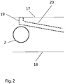
Fig. 2 shows an enlargement of the permeate apertures according to one embodiment of the invention. -
Fig. 3 shows a housing according to the invention. -
Fig. 4 shows an alternative housing according to the invention. -
Fig. 5 shows a stack of housings according to the invention. - In a first aspect illustrated by
Figures 1 - 2 , the present invention discloses adistribution plate 1 for supplying crossflow filtration cassettes with fluids. The distribution plate comprises asurface 17; twoopposite end walls 21; twoopposite side walls 22; afeed channel 2 which is in fluid communication with afeed inlet port 3 and with a plurality of feed apertures 4 which open into the surface; aretentate channel 5 in fluid communication with aretentate outlet port 6; and with a plurality ofretentate apertures 7 which open into the surface; and apermeate channel 8 in fluid communication with twopermeate outlet ports 9,10 and with a plurality ofpermeate apertures 11 which open into the surface. The feed channel, the retentate channel and the permeate channel extend in a direction essentially parallel with one or both of the side walls. The feed apertures are grouped at a first area on the surface, the retentate apertures are grouped at a second area on the surface and the permeate apertures are located at the first and/or the second area. A plurality ofpermeate connector channels 14 extend inside the plate from at least oneregion permeate channel 8, adjacent thepermeate outlet ports 9,10 and these permeate connector channels provide fluidic communication between the permeate apertures and the permeate channel. Theregions surface 17. The permeate channel can further e.g. go right through the plate from onewall 21;22 to anopposite wall 21;22. The feed and retentate channels can e.g. end inside the plate with an aperture located at the end of each channel. The feed, retentate and permeate channels as well as the permeate connector channels can suitably all be located inside the plate. There will then not be any need for additional sealing surfaces along any of the channels. During use, the plate can be upstanding with the feed, retentate and permeate channels extending in a vertical direction. The plate can be manufactured from metal, such as one or more corrosion-resistant metals of high modulus, e.g. stainless steel or titanium. It can also be manufactured from plastics, such as a low leachables plastic of high modulus, e.g. PEEK. Metal plates can be used also for large distributor plates where high clamping forces are needed, while plastic plates may be limited to lower clamping force applications. Plastic plates may however be used at higher clamping pressures if they are supported by a metal plate or metal frame structure. - In some embodiments, the feed inlet port, the retentate outlet port and the permeate outlet ports are located on the end walls. The
permeate outlet ports 9,10 can suitably be located on opposite end walls. An advantage of locatingports 9,10 on opposite end walls is that it facilitates draining and deaeration and it also facilitates the assembly of several plates in a stack of housings. - In certain embodiments, the
permeate connector channels 14 are acutely angled towards thepermeate channel 8. The angle between each permeate connector and the permeate channel can suitably be 20 - 80 degrees, such as 30 - 70 degrees. During use with an upstanding plate the acute angles facilitate draining and deaeration. The permeate connector channels can further be acutely angled with respect to thesurface 17, such as with an angle of 1-30 degrees, e.g. 5 - 15 degrees. - In some embodiments, at least one, such as at least two of the permeate connector channels originate from each of the
regions - In certain embodiments, the feed apertures are aligned along a first
straight line 12 and the retentate apertures are aligned along a secondstraight line 13. Thepermeate apertures 11 can be aligned with the feed and/or retentate apertures along one or both of the first or second straight line. They can also be aligned with an offset, e.g. at a distance of less than 5 mm from the first or second line. - In some embodiments, the
permeate connector channels 14 each comprise two legs: anaperture leg 19 which is essentially perpendicular to thesurface 17 and which ends in a permeate aperture; and aconnector leg 20, which fluidically connects the aperture leg with thepermeate channel 8. An advantage of this is that the two legs can be drilled from different directions, the connector leg from the permeate channel and the aperture leg from the surface. This has the effect that the apertures can be made circular as opposed to elongated in the prior art plates. An advantage of having circular apertures is that the circular shape allows higher flow rates. A further advantage is that cassettes typically have circular apertures and the alignment between two circular apertures provides a sanitary flow-path without dead-legs. - In certain embodiments, the feed channel, the retentate channel, the permeate channel and the permeate connector channels have essentially circular cross sections or are composed of segments having essentially circular cross sections. Channels with circular cross sections provide high flow rates for a given diameter and are also advantageous from a sanitation point of view. The channel segments can e.g. be either cylindrical or frustoconical.
- In some embodiments, the feed channel, the retentate channel, the permeate channel and the first and second lines are essentially parallel. They can be completely parallel or they may be angled less than 20 degrees, such as less than 10 degrees, in relation to each other.
- In certain embodiments, the feed apertures, the retentate apertures and the permeate apertures are all located on the
surface 17. If thesurface 17 is a front surface, all the apertures will then be located on the same side of the plate. Such a single-faced distributor plate is easy to manufacture and handle and is useful in many different scales of processes. Single-faced distributor plates can be used e.g. in the housing shown inFigure 3 . - In some embodiments, the surface includes a
front surface 17 and arear surface 18 which are planar and parallel and wherein the feed apertures, the retentate apertures and the permeate apertures are located on both the front 17 and the rear 18 surfaces. The distributor plate will then be double-sided, which can be advantageous particularly in large scale processes where one plate can then supply a larger number of cassettes. Double-faced distributor plates can be used e.g. in the housing shown inFigure 4 . - In certain embodiments, the plate may comprise pressure sensors. These can be mounted inside any of the channels in order to monitor e.g. the transmembrane pressure during filtration. The sensors can be wireless and may communicate with a receiver or control unit via radiofrequency signals.
- In a second aspect, illustrated by
Figures 3 - 4 , the invention discloses ahousing 30;40 for crossflow filtration cassettes, comprising adistributor plate 31;41 as described in any of the above embodiments, at least oneend plate 32;42 and abase frame 33;43 that is configured to permit relative movement of the distributor plate and the end plate or end plates along an axis perpendicular to the surface of the distributor plate. The base frame may e.g. comprise a plurality of rods attached to the distributor plate and to at least onesupport plate 34;44. The end plate can then have holes corresponding to the rods and it can slide along the rods.Figure 3 shows a housing with one end plate and a single-faced distributor plate.Figure 4 shows a housing with two end plates and a double-faced distributor plate. - In certain embodiments the housing further comprises at least one pneumatic or hydraulic piston affixed to the base frame to move at least one end plate towards and away from the distributor plate. The piston(s) can e.g. be attached to the support plate(s) 34;44.
- In some embodiments the distributor plate is upstanding with the surface and the side walls vertically oriented. The feed, retentate and permeate channels will then extend in a vertical direction and drainage and aeration can take place through them and the angled permeate connector channels.
- In certain embodiments the housing comprises at least one filtration cassette clamped between the distributor plate and an end plate. The cassette should have feed, retentate and permeate apertures in a pattern corresponding to the pattern of apertures on the distributor plate surface. The number of cassettes clamped between a distributor plate and an end plate can be from 1 to 20, such as 1 to 10 cassettes.
- In a third aspect, illustrated by
Figure 5 , the invention discloses avertical stack 50 of at least two housings as described above, wherein thefeed inlet ports 51 of eachdistributor plate 52 are fluidically connected in parallel, theretentate outlet ports 53 of each distributor plate are fluidically connected in parallel and thepermeate outlet ports 54 of each distributor plate are fluidically connected in series. An advantage of the serially connected permeate outlet ports is that drainage and deaeration of the stack is facilitated. The permeate outlet ports can suitably be connected with tubing extending in a vertical direction. - In a fourth aspect, the invention discloses a method of manufacturing a distributor plate as described above. The method comprises the steps of:
- a) providing a solid plate body,
- b) drilling the feed, retentate and permeate channels in the solid plate body,
- c) drilling the permeate connector channels and the feed and retentate connector channels in the plate body. The solid plate body can be manufactured from metal, e.g. a corrosion resistant metal of high modulus, such as e.g. stainless steel or titanium. It can also be manufactured from plastics, in particular for smaller scale plates where lower clamping forces are required.
- In some embodiments, the method further comprises a step d) of mounting the feed inlet port, the retentate outlet port and the permeate outlet port(s). The ports can e.g. be mounted by welding. The welding can then be performed so that no pores are formed in the flow-path. The plate can e.g. be machined to provide a tubular protrusion around each channel opening and the ports can be butt welded on the protrusions. Alternatively, the ports can be threaded and mounted using corresponding threads located in the channel openings, optionally with sealing gaskets. An alternative to mounted ports can be that the ports are shaped integrally in the plate body at the channel openings. This can be done e.g. by machining flanges directly from the plate body.
- In certain embodiments, in step c) of the method, the
connector legs 20 of the permeate connector channels are drilled acutely from the permeate channel in theregions - This written description uses examples to disclose the invention, including the best mode, and also to enable any person skilled in the art to practice the invention, including making and using any devices or systems and performing any incorporated methods. The patentable scope of the invention is defined by the claims, and may include other examples that occur to those skilled in the art. Such other examples are intended to be within the scope of the claims if they have structural elements that do not differ from the literal language of the claims, or if they include equivalent structural elements with insubstantial differences from the literal languages of the claims. It is pointed out that any feature described in relation to one embodiment may be used also in combination with one or more features of any other of the aspects and embodiments described.
Claims (15)
- A distribution plate (1) for supplying crossflow filtration cassettes, the plate comprising a surface (17), two opposite end walls (21), two opposite side walls (22), a feed channel (2) in fluid communication with a feed inlet port (3) and with a plurality of feed apertures (4) which open into the surface; a retentate channel (5) in fluid communication with a retentate outlet port (6), and with a plurality of retentate apertures (7) which open into the surface; and a permeate channel (8) in fluid communication with two permeate outlet ports (9,10) located on opposite end walls and with a plurality of permeate apertures (11) which open into the surface;
wherein said feed channel, said retentate channel and said permeate channel extend in a vertical direction parallel with one or both side walls;
wherein said feed apertures are grouped at a first area on the surface, said retentate apertures are grouped at a second area on the surface;
wherein said permeate apertures are located at the first and/or the second area; and
wherein a plurality of permeate connector channels (14) extend inside the plate from at least one region (15,16) of the permeate channel (8), adjacent the permeate outlet ports (9,10) and said permeate connector channels provide fluidic communication between the permeate apertures and the permeate channel,
wherein the angle between each permeate connector channel and the permeate channel is 20-80 degrees. - The distribution plate according to claim 1, wherein said feed inlet port, said retentate outlet port and said permeate outlet ports are located on the end walls.
- The distribution plate according to any preceding claim, wherein at least one, such as at least two, permeate connector channels originate from each of the regions (15,16).
- The distribution plate according to any preceding claim, wherein said feed apertures are aligned along a first straight line (12) and said retentate apertures are aligned along a second straight line (13).
- The distribution plate according to claim 6, wherein the permeate apertures (11) are aligned with the feed and/or retentate apertures along at least one of said first or second straight line.
- The distributor plate according to any preceding claim, wherein said permeate connector channels (14) each comprise two legs: an aperture leg (19) perpendicular to the surface (17) and ending in a permeate aperture, and a connector leg (20), connecting the aperture leg with the permeate channel (8).
- The distributor plate according to any preceding claim, wherein said permeate apertures are circular.
- The distributor plate according to any preceding claim, wherein said feed channel, said retentate channel, said permeate channel and said permeate connector channels have circular cross sections or are composed of segments having circular cross sections.
- The distributor plate according to any preceding claim, wherein said feed channel, said retentate channel, said permeate channel and said first and second lines are essentially parallel.
- The distributor plate according to any preceding claim, wherein said feed apertures, said retentate apertures and said permeate apertures are all located on the surface (17).
- The distributor plate according to any one of claims 1-9, wherein the surface includes a front surface (17) and a rear surface (18) which are planar and parallel and wherein said feed apertures, said retentate apertures and said permeate apertures are located on both the front (17) and the rear (18) surfaces.
- The distributor plate according to any preceding claim, wherein said at least one region (15,16) of the permeate channel (8) is located within a distance of two permeate channel diameters from an end wall (21).
- A housing (30;40) for crossflow filtration cassettes, comprising the distributor plate (31;41) of any preceding claim, at least one end plate (32;42) and a base frame (33;43) that is configured to permit relative movement of the distributor plate and the end plate or end plates along an axis perpendicular to the surface of the distributor plate, by the end frame comprising a plurality of rods attached to the distributor plate and to at least one support plate (34,44), with the end plate having holes corresponding to the rods such that it can slide along the rods.
- The housing according to claim 13, which is adapted to form a vertical stack with at least one like housing, wherein the feed inlet port (51) is adapted to be fluidically connected in parallel with a feed inlet port of a like housing, the retentate outlet port (53) is adapted to be fluidically connected in parallel with a retentate outlet port of the like housing and the permeate outlet ports (54) are adapted to be fluidically connected in series with permeate outlet ports of the like housing.
- A vertical stack (50) of at least two housings according to claim 13, wherein the feed inlet ports (51) of each distributor plate (52) are fluidically connected in parallel, the retentate outlet ports (53) of each distributor plate are fluidically connected in parallel and the permeate outlet ports (54) of each distributor plate are fluidically connected in series.
Applications Claiming Priority (2)
| Application Number | Priority Date | Filing Date | Title |
|---|---|---|---|
| SE1151222 | 2011-12-20 | ||
| PCT/SE2012/051403 WO2013095268A1 (en) | 2011-12-20 | 2012-12-17 | Distribution plate for crossflow filtration cassettes |
Publications (3)
| Publication Number | Publication Date |
|---|---|
| EP2794077A1 EP2794077A1 (en) | 2014-10-29 |
| EP2794077A4 EP2794077A4 (en) | 2015-06-03 |
| EP2794077B1 true EP2794077B1 (en) | 2017-04-12 |
Family
ID=48668963
Family Applications (1)
| Application Number | Title | Priority Date | Filing Date |
|---|---|---|---|
| EP12860775.1A Active EP2794077B1 (en) | 2011-12-20 | 2012-12-17 | Distribution plate for crossflow filtration cassettes |
Country Status (6)
| Country | Link |
|---|---|
| US (1) | US9718028B2 (en) |
| EP (1) | EP2794077B1 (en) |
| JP (1) | JP6266531B2 (en) |
| CN (1) | CN104023828B (en) |
| IN (1) | IN2014DN03082A (en) |
| WO (1) | WO2013095268A1 (en) |
Families Citing this family (7)
| Publication number | Priority date | Publication date | Assignee | Title |
|---|---|---|---|---|
| ES2935333T3 (en) * | 2014-08-29 | 2023-03-06 | Emd Millipore Corp | Processes for filtering liquids using single pass tangential flow filtration systems and tangential flow filtration systems with recirculation of retentate |
| DE102015122261B3 (en) * | 2015-12-18 | 2017-01-12 | Sartorius Stedim Biotech Gmbh | Kassetteneinspannvorrichtung |
| DE102018004890B4 (en) * | 2018-06-19 | 2023-03-16 | Sartorius Stedim Biotech Gmbh | Filter system for biopharmaceutical processes, manifold plate for a filter system and method of making a filter system |
| EP3835402B1 (en) * | 2019-12-09 | 2025-10-15 | Sartorius Stedim Biotech GmbH | Modular processing system |
| KR20210132921A (en) * | 2020-04-28 | 2021-11-05 | 주식회사 아모그린텍 | filter module for water-purifying device using gravity and water-purifying device including the same |
| US12263449B2 (en) * | 2021-06-14 | 2025-04-01 | John F. Connors, Jr. | Tangential flow filtration manifold |
| USD1094639S1 (en) * | 2023-07-24 | 2025-09-23 | Merck Millipore Ltd. | Filter holder |
Family Cites Families (8)
| Publication number | Priority date | Publication date | Assignee | Title |
|---|---|---|---|---|
| US5147542A (en) | 1991-02-04 | 1992-09-15 | Millipore Corporation | Manifold and manifold segment for tangential flow filtration apparatus |
| US5176828A (en) * | 1991-02-04 | 1993-01-05 | Millipore Corporation | Manifold segment stack with intermediate feed manifold |
| GB2348381B (en) | 1998-11-04 | 2001-02-21 | Sartorius Gmbh | Distributor plate for crossflow cassette filtration apparatus |
| DE19850707C1 (en) * | 1998-11-04 | 2000-05-18 | Sartorius Gmbh | Distribution plate for crossflow cassette filtration devices |
| US6506300B2 (en) | 2001-05-15 | 2003-01-14 | Sartorius Ag | Distributor plate for crossflow cassette-type filtration appliances |
| US7635426B2 (en) | 2002-11-08 | 2009-12-22 | Ge Healthcare Bio-Sciences Corp. | Tangential filtration housing |
| DE102006009804B4 (en) * | 2006-03-01 | 2009-02-12 | Sartorius Stedim Biotech Gmbh | Cassette stack jig |
| FR2960160B1 (en) | 2010-05-19 | 2012-08-17 | Millipore Corp | FLUID BOND BLOCK FOR FILTRATION DEVICE HAVING AT LEAST ONE FILTER CASSETTE |
-
2012
- 2012-12-17 EP EP12860775.1A patent/EP2794077B1/en active Active
- 2012-12-17 WO PCT/SE2012/051403 patent/WO2013095268A1/en not_active Ceased
- 2012-12-17 US US14/359,328 patent/US9718028B2/en active Active
- 2012-12-17 IN IN3082DEN2014 patent/IN2014DN03082A/en unknown
- 2012-12-17 JP JP2014548734A patent/JP6266531B2/en active Active
- 2012-12-17 CN CN201280063162.9A patent/CN104023828B/en active Active
Non-Patent Citations (1)
| Title |
|---|
| None * |
Also Published As
| Publication number | Publication date |
|---|---|
| JP2015500741A (en) | 2015-01-08 |
| EP2794077A1 (en) | 2014-10-29 |
| CN104023828B (en) | 2017-09-26 |
| JP6266531B2 (en) | 2018-01-24 |
| US20140305860A1 (en) | 2014-10-16 |
| IN2014DN03082A (en) | 2015-05-15 |
| US9718028B2 (en) | 2017-08-01 |
| WO2013095268A1 (en) | 2013-06-27 |
| CN104023828A (en) | 2014-09-03 |
| EP2794077A4 (en) | 2015-06-03 |
Similar Documents
| Publication | Publication Date | Title |
|---|---|---|
| US9718028B2 (en) | Distribution plate for crossflow filtration cassettes | |
| JP5283618B2 (en) | Hollow fiber membrane module and method for producing the same, hollow fiber membrane module assembly and method for purifying suspended water using them | |
| AU2013200833B2 (en) | Improved manifold arrangement | |
| DE10000186C2 (en) | Device and system for crossflow filtration | |
| RU2455053C2 (en) | Filtration module and its arrangement in filtration system | |
| US7037426B2 (en) | Immersed membrane apparatus | |
| US8945387B2 (en) | Hollow fiber membrane module for use in a tubular pressure vessel | |
| JP2015500741A5 (en) | ||
| US10130915B2 (en) | Self supporting structure for membrane crossflow cartridges | |
| JP2013052386A (en) | Hollow fiber membrane module and hollow fiber membrane module unit | |
| US10583399B2 (en) | Modular distributor head for membrane housing bodies | |
| US11633697B2 (en) | Disposable device for filtering a large medium volume | |
| AU2014326293A1 (en) | Self supporting structure for membrane crossflow cartridges | |
| JP6010466B2 (en) | Seawater desalination system and energy recovery device | |
| KR101889587B1 (en) | A permeate collection fitting | |
| WO2002094421A1 (en) | Immersed membrane apparatus | |
| EP2445616B1 (en) | Simulator device | |
| KR101557544B1 (en) | Hollow fiber membrane module | |
| JP2021527566A (en) | Filter system for biopharmacy process | |
| JP2024517650A (en) | FILTER BOX AND RETRIEVABLE SUBSEA FILTER MODULE COMPRISING FILTER BOX - Patent application | |
| CN210150771U (en) | Internal and external pressure integrated ultrafiltration device | |
| EP1946824B1 (en) | Filtration assemblies with common manifold and use therof | |
| JP2006247608A (en) | Membrane module | |
| BR112021010424B1 (en) | FILTER DEVICE, MEMBRANE FILTER UNIT, USE OF FILTER DEVICE, AND METHOD FOR INSTALLING A PLURALITY OF MEMBRANE FILTER UNITS |
Legal Events
| Date | Code | Title | Description |
|---|---|---|---|
| PUAI | Public reference made under article 153(3) epc to a published international application that has entered the european phase |
Free format text: ORIGINAL CODE: 0009012 |
|
| 17P | Request for examination filed |
Effective date: 20140611 |
|
| AK | Designated contracting states |
Kind code of ref document: A1 Designated state(s): AL AT BE BG CH CY CZ DE DK EE ES FI FR GB GR HR HU IE IS IT LI LT LU LV MC MK MT NL NO PL PT RO RS SE SI SK SM TR |
|
| DAX | Request for extension of the european patent (deleted) | ||
| RA4 | Supplementary search report drawn up and despatched (corrected) |
Effective date: 20150504 |
|
| RIC1 | Information provided on ipc code assigned before grant |
Ipc: B01D 63/08 20060101AFI20150424BHEP Ipc: B01D 65/00 20060101ALI20150424BHEP |
|
| 17Q | First examination report despatched |
Effective date: 20150724 |
|
| GRAP | Despatch of communication of intention to grant a patent |
Free format text: ORIGINAL CODE: EPIDOSNIGR1 |
|
| INTG | Intention to grant announced |
Effective date: 20161027 |
|
| GRAS | Grant fee paid |
Free format text: ORIGINAL CODE: EPIDOSNIGR3 |
|
| GRAA | (expected) grant |
Free format text: ORIGINAL CODE: 0009210 |
|
| AK | Designated contracting states |
Kind code of ref document: B1 Designated state(s): AL AT BE BG CH CY CZ DE DK EE ES FI FR GB GR HR HU IE IS IT LI LT LU LV MC MK MT NL NO PL PT RO RS SE SI SK SM TR |
|
| REG | Reference to a national code |
Ref country code: GB Ref legal event code: FG4D |
|
| REG | Reference to a national code |
Ref country code: CH Ref legal event code: EP |
|
| REG | Reference to a national code |
Ref country code: IE Ref legal event code: FG4D |
|
| REG | Reference to a national code |
Ref country code: AT Ref legal event code: REF Ref document number: 883295 Country of ref document: AT Kind code of ref document: T Effective date: 20170515 |
|
| REG | Reference to a national code |
Ref country code: DE Ref legal event code: R096 Ref document number: 602012031185 Country of ref document: DE |
|
| REG | Reference to a national code |
Ref country code: NL Ref legal event code: MP Effective date: 20170412 |
|
| REG | Reference to a national code |
Ref country code: LT Ref legal event code: MG4D |
|
| REG | Reference to a national code |
Ref country code: AT Ref legal event code: MK05 Ref document number: 883295 Country of ref document: AT Kind code of ref document: T Effective date: 20170412 |
|
| PG25 | Lapsed in a contracting state [announced via postgrant information from national office to epo] |
Ref country code: NL Free format text: LAPSE BECAUSE OF FAILURE TO SUBMIT A TRANSLATION OF THE DESCRIPTION OR TO PAY THE FEE WITHIN THE PRESCRIBED TIME-LIMIT Effective date: 20170412 |
|
| PG25 | Lapsed in a contracting state [announced via postgrant information from national office to epo] |
Ref country code: ES Free format text: LAPSE BECAUSE OF FAILURE TO SUBMIT A TRANSLATION OF THE DESCRIPTION OR TO PAY THE FEE WITHIN THE PRESCRIBED TIME-LIMIT Effective date: 20170412 Ref country code: GR Free format text: LAPSE BECAUSE OF FAILURE TO SUBMIT A TRANSLATION OF THE DESCRIPTION OR TO PAY THE FEE WITHIN THE PRESCRIBED TIME-LIMIT Effective date: 20170713 Ref country code: LT Free format text: LAPSE BECAUSE OF FAILURE TO SUBMIT A TRANSLATION OF THE DESCRIPTION OR TO PAY THE FEE WITHIN THE PRESCRIBED TIME-LIMIT Effective date: 20170412 Ref country code: AT Free format text: LAPSE BECAUSE OF FAILURE TO SUBMIT A TRANSLATION OF THE DESCRIPTION OR TO PAY THE FEE WITHIN THE PRESCRIBED TIME-LIMIT Effective date: 20170412 Ref country code: HR Free format text: LAPSE BECAUSE OF FAILURE TO SUBMIT A TRANSLATION OF THE DESCRIPTION OR TO PAY THE FEE WITHIN THE PRESCRIBED TIME-LIMIT Effective date: 20170412 Ref country code: FI Free format text: LAPSE BECAUSE OF FAILURE TO SUBMIT A TRANSLATION OF THE DESCRIPTION OR TO PAY THE FEE WITHIN THE PRESCRIBED TIME-LIMIT Effective date: 20170412 Ref country code: NO Free format text: LAPSE BECAUSE OF FAILURE TO SUBMIT A TRANSLATION OF THE DESCRIPTION OR TO PAY THE FEE WITHIN THE PRESCRIBED TIME-LIMIT Effective date: 20170712 |
|
| PG25 | Lapsed in a contracting state [announced via postgrant information from national office to epo] |
Ref country code: BG Free format text: LAPSE BECAUSE OF FAILURE TO SUBMIT A TRANSLATION OF THE DESCRIPTION OR TO PAY THE FEE WITHIN THE PRESCRIBED TIME-LIMIT Effective date: 20170712 Ref country code: SE Free format text: LAPSE BECAUSE OF FAILURE TO SUBMIT A TRANSLATION OF THE DESCRIPTION OR TO PAY THE FEE WITHIN THE PRESCRIBED TIME-LIMIT Effective date: 20170412 Ref country code: IS Free format text: LAPSE BECAUSE OF FAILURE TO SUBMIT A TRANSLATION OF THE DESCRIPTION OR TO PAY THE FEE WITHIN THE PRESCRIBED TIME-LIMIT Effective date: 20170812 Ref country code: RS Free format text: LAPSE BECAUSE OF FAILURE TO SUBMIT A TRANSLATION OF THE DESCRIPTION OR TO PAY THE FEE WITHIN THE PRESCRIBED TIME-LIMIT Effective date: 20170412 Ref country code: LV Free format text: LAPSE BECAUSE OF FAILURE TO SUBMIT A TRANSLATION OF THE DESCRIPTION OR TO PAY THE FEE WITHIN THE PRESCRIBED TIME-LIMIT Effective date: 20170412 Ref country code: PL Free format text: LAPSE BECAUSE OF FAILURE TO SUBMIT A TRANSLATION OF THE DESCRIPTION OR TO PAY THE FEE WITHIN THE PRESCRIBED TIME-LIMIT Effective date: 20170412 |
|
| REG | Reference to a national code |
Ref country code: FR Ref legal event code: PLFP Year of fee payment: 6 |
|
| REG | Reference to a national code |
Ref country code: DE Ref legal event code: R097 Ref document number: 602012031185 Country of ref document: DE |
|
| PG25 | Lapsed in a contracting state [announced via postgrant information from national office to epo] |
Ref country code: EE Free format text: LAPSE BECAUSE OF FAILURE TO SUBMIT A TRANSLATION OF THE DESCRIPTION OR TO PAY THE FEE WITHIN THE PRESCRIBED TIME-LIMIT Effective date: 20170412 Ref country code: DK Free format text: LAPSE BECAUSE OF FAILURE TO SUBMIT A TRANSLATION OF THE DESCRIPTION OR TO PAY THE FEE WITHIN THE PRESCRIBED TIME-LIMIT Effective date: 20170412 Ref country code: RO Free format text: LAPSE BECAUSE OF FAILURE TO SUBMIT A TRANSLATION OF THE DESCRIPTION OR TO PAY THE FEE WITHIN THE PRESCRIBED TIME-LIMIT Effective date: 20170412 Ref country code: CZ Free format text: LAPSE BECAUSE OF FAILURE TO SUBMIT A TRANSLATION OF THE DESCRIPTION OR TO PAY THE FEE WITHIN THE PRESCRIBED TIME-LIMIT Effective date: 20170412 Ref country code: SK Free format text: LAPSE BECAUSE OF FAILURE TO SUBMIT A TRANSLATION OF THE DESCRIPTION OR TO PAY THE FEE WITHIN THE PRESCRIBED TIME-LIMIT Effective date: 20170412 |
|
| PLBE | No opposition filed within time limit |
Free format text: ORIGINAL CODE: 0009261 |
|
| STAA | Information on the status of an ep patent application or granted ep patent |
Free format text: STATUS: NO OPPOSITION FILED WITHIN TIME LIMIT |
|
| PG25 | Lapsed in a contracting state [announced via postgrant information from national office to epo] |
Ref country code: IT Free format text: LAPSE BECAUSE OF FAILURE TO SUBMIT A TRANSLATION OF THE DESCRIPTION OR TO PAY THE FEE WITHIN THE PRESCRIBED TIME-LIMIT Effective date: 20170412 Ref country code: SM Free format text: LAPSE BECAUSE OF FAILURE TO SUBMIT A TRANSLATION OF THE DESCRIPTION OR TO PAY THE FEE WITHIN THE PRESCRIBED TIME-LIMIT Effective date: 20170412 |
|
| 26N | No opposition filed |
Effective date: 20180115 |
|
| PG25 | Lapsed in a contracting state [announced via postgrant information from national office to epo] |
Ref country code: SI Free format text: LAPSE BECAUSE OF FAILURE TO SUBMIT A TRANSLATION OF THE DESCRIPTION OR TO PAY THE FEE WITHIN THE PRESCRIBED TIME-LIMIT Effective date: 20170412 |
|
| REG | Reference to a national code |
Ref country code: CH Ref legal event code: PL |
|
| REG | Reference to a national code |
Ref country code: IE Ref legal event code: MM4A |
|
| PG25 | Lapsed in a contracting state [announced via postgrant information from national office to epo] |
Ref country code: MT Free format text: LAPSE BECAUSE OF NON-PAYMENT OF DUE FEES Effective date: 20171217 Ref country code: LU Free format text: LAPSE BECAUSE OF NON-PAYMENT OF DUE FEES Effective date: 20171217 |
|
| REG | Reference to a national code |
Ref country code: BE Ref legal event code: MM Effective date: 20171231 |
|
| PG25 | Lapsed in a contracting state [announced via postgrant information from national office to epo] |
Ref country code: IE Free format text: LAPSE BECAUSE OF NON-PAYMENT OF DUE FEES Effective date: 20171217 |
|
| PG25 | Lapsed in a contracting state [announced via postgrant information from national office to epo] |
Ref country code: LI Free format text: LAPSE BECAUSE OF NON-PAYMENT OF DUE FEES Effective date: 20171231 Ref country code: BE Free format text: LAPSE BECAUSE OF NON-PAYMENT OF DUE FEES Effective date: 20171231 Ref country code: CH Free format text: LAPSE BECAUSE OF NON-PAYMENT OF DUE FEES Effective date: 20171231 |
|
| PG25 | Lapsed in a contracting state [announced via postgrant information from national office to epo] |
Ref country code: HU Free format text: LAPSE BECAUSE OF FAILURE TO SUBMIT A TRANSLATION OF THE DESCRIPTION OR TO PAY THE FEE WITHIN THE PRESCRIBED TIME-LIMIT; INVALID AB INITIO Effective date: 20121217 Ref country code: MC Free format text: LAPSE BECAUSE OF FAILURE TO SUBMIT A TRANSLATION OF THE DESCRIPTION OR TO PAY THE FEE WITHIN THE PRESCRIBED TIME-LIMIT Effective date: 20170412 |
|
| PG25 | Lapsed in a contracting state [announced via postgrant information from national office to epo] |
Ref country code: CY Free format text: LAPSE BECAUSE OF FAILURE TO SUBMIT A TRANSLATION OF THE DESCRIPTION OR TO PAY THE FEE WITHIN THE PRESCRIBED TIME-LIMIT Effective date: 20170412 |
|
| PG25 | Lapsed in a contracting state [announced via postgrant information from national office to epo] |
Ref country code: MK Free format text: LAPSE BECAUSE OF FAILURE TO SUBMIT A TRANSLATION OF THE DESCRIPTION OR TO PAY THE FEE WITHIN THE PRESCRIBED TIME-LIMIT Effective date: 20170412 |
|
| PG25 | Lapsed in a contracting state [announced via postgrant information from national office to epo] |
Ref country code: TR Free format text: LAPSE BECAUSE OF FAILURE TO SUBMIT A TRANSLATION OF THE DESCRIPTION OR TO PAY THE FEE WITHIN THE PRESCRIBED TIME-LIMIT Effective date: 20170412 |
|
| PG25 | Lapsed in a contracting state [announced via postgrant information from national office to epo] |
Ref country code: PT Free format text: LAPSE BECAUSE OF FAILURE TO SUBMIT A TRANSLATION OF THE DESCRIPTION OR TO PAY THE FEE WITHIN THE PRESCRIBED TIME-LIMIT Effective date: 20170412 |
|
| PG25 | Lapsed in a contracting state [announced via postgrant information from national office to epo] |
Ref country code: AL Free format text: LAPSE BECAUSE OF FAILURE TO SUBMIT A TRANSLATION OF THE DESCRIPTION OR TO PAY THE FEE WITHIN THE PRESCRIBED TIME-LIMIT Effective date: 20170412 |
|
| REG | Reference to a national code |
Ref country code: DE Ref legal event code: R081 Ref document number: 602012031185 Country of ref document: DE Owner name: CYTIVA SWEDEN AB, SE Free format text: FORMER OWNER: GE HEALTHCARE BIO-SCIENCES AB, UPPSALA, SE |
|
| P01 | Opt-out of the competence of the unified patent court (upc) registered |
Effective date: 20230526 |
|
| PGFP | Annual fee paid to national office [announced via postgrant information from national office to epo] |
Ref country code: GB Payment date: 20251223 Year of fee payment: 14 |
|
| PGFP | Annual fee paid to national office [announced via postgrant information from national office to epo] |
Ref country code: FR Payment date: 20251230 Year of fee payment: 14 |
|
| PGFP | Annual fee paid to national office [announced via postgrant information from national office to epo] |
Ref country code: DE Payment date: 20251229 Year of fee payment: 14 |