EP2793734B1 - Dental device for enhancing bone growth - Google Patents
Dental device for enhancing bone growth Download PDFInfo
- Publication number
- EP2793734B1 EP2793734B1 EP12859870.3A EP12859870A EP2793734B1 EP 2793734 B1 EP2793734 B1 EP 2793734B1 EP 12859870 A EP12859870 A EP 12859870A EP 2793734 B1 EP2793734 B1 EP 2793734B1
- Authority
- EP
- European Patent Office
- Prior art keywords
- patient
- implant
- bone
- rig
- receiving
- Prior art date
- Legal status (The legal status is an assumption and is not a legal conclusion. Google has not performed a legal analysis and makes no representation as to the accuracy of the status listed.)
- Not-in-force
Links
- 230000008468 bone growth Effects 0.000 title claims description 7
- 230000002708 enhancing effect Effects 0.000 title description 2
- 239000007943 implant Substances 0.000 claims description 98
- 210000000988 bone and bone Anatomy 0.000 claims description 94
- 238000000034 method Methods 0.000 claims description 90
- 239000004053 dental implant Substances 0.000 claims description 20
- 210000001847 jaw Anatomy 0.000 claims description 12
- 239000000463 material Substances 0.000 claims description 8
- 239000000560 biocompatible material Substances 0.000 claims description 7
- 238000002591 computed tomography Methods 0.000 claims description 7
- 238000005094 computer simulation Methods 0.000 claims description 5
- 238000013461 design Methods 0.000 claims description 5
- 210000004373 mandible Anatomy 0.000 claims description 5
- 210000001585 trabecular meshwork Anatomy 0.000 claims description 5
- 229910001069 Ti alloy Inorganic materials 0.000 claims description 4
- 238000000149 argon plasma sintering Methods 0.000 claims description 3
- 238000000151 deposition Methods 0.000 claims description 3
- 238000007648 laser printing Methods 0.000 claims description 3
- QCWXUUIWCKQGHC-UHFFFAOYSA-N Zirconium Chemical compound [Zr] QCWXUUIWCKQGHC-UHFFFAOYSA-N 0.000 claims description 2
- 238000010276 construction Methods 0.000 claims description 2
- 230000001815 facial effect Effects 0.000 claims description 2
- 238000007639 printing Methods 0.000 claims description 2
- 229910052726 zirconium Inorganic materials 0.000 claims description 2
- 238000002513 implantation Methods 0.000 claims 1
- 210000002050 maxilla Anatomy 0.000 claims 1
- 230000035515 penetration Effects 0.000 claims 1
- 230000035876 healing Effects 0.000 description 25
- 210000004027 cell Anatomy 0.000 description 20
- 238000001356 surgical procedure Methods 0.000 description 13
- 239000000126 substance Substances 0.000 description 10
- 210000003484 anatomy Anatomy 0.000 description 9
- 206010065687 Bone loss Diseases 0.000 description 5
- 210000004379 membrane Anatomy 0.000 description 5
- 239000012528 membrane Substances 0.000 description 5
- 210000004872 soft tissue Anatomy 0.000 description 5
- RTAQQCXQSZGOHL-UHFFFAOYSA-N Titanium Chemical compound [Ti] RTAQQCXQSZGOHL-UHFFFAOYSA-N 0.000 description 4
- 238000005516 engineering process Methods 0.000 description 4
- 238000004519 manufacturing process Methods 0.000 description 4
- 239000011159 matrix material Substances 0.000 description 4
- 229910052751 metal Inorganic materials 0.000 description 4
- 239000002184 metal Substances 0.000 description 4
- 210000000006 pectoral fin Anatomy 0.000 description 4
- 229910052719 titanium Inorganic materials 0.000 description 4
- 239000010936 titanium Substances 0.000 description 4
- 230000003444 anaesthetic effect Effects 0.000 description 3
- 239000002131 composite material Substances 0.000 description 3
- 238000012986 modification Methods 0.000 description 3
- 230000004048 modification Effects 0.000 description 3
- 238000010883 osseointegration Methods 0.000 description 3
- 238000010146 3D printing Methods 0.000 description 2
- 241000283690 Bos taurus Species 0.000 description 2
- 241001465754 Metazoa Species 0.000 description 2
- 206010028980 Neoplasm Diseases 0.000 description 2
- 239000000654 additive Substances 0.000 description 2
- 230000000996 additive effect Effects 0.000 description 2
- 229910045601 alloy Inorganic materials 0.000 description 2
- 239000000956 alloy Substances 0.000 description 2
- 201000011510 cancer Diseases 0.000 description 2
- PCHJSUWPFVWCPO-UHFFFAOYSA-N gold Chemical compound [Au] PCHJSUWPFVWCPO-UHFFFAOYSA-N 0.000 description 2
- 229910052737 gold Inorganic materials 0.000 description 2
- 239000010931 gold Substances 0.000 description 2
- 230000012010 growth Effects 0.000 description 2
- 238000003384 imaging method Methods 0.000 description 2
- 230000010354 integration Effects 0.000 description 2
- 229910052573 porcelain Inorganic materials 0.000 description 2
- 108010023728 Alloderm Proteins 0.000 description 1
- 229910000497 Amalgam Inorganic materials 0.000 description 1
- 241000894006 Bacteria Species 0.000 description 1
- 102000007350 Bone Morphogenetic Proteins Human genes 0.000 description 1
- 108010007726 Bone Morphogenetic Proteins Proteins 0.000 description 1
- 229910000807 Ga alloy Inorganic materials 0.000 description 1
- 208000023329 Gun shot wound Diseases 0.000 description 1
- 241000124008 Mammalia Species 0.000 description 1
- 108020004511 Recombinant DNA Proteins 0.000 description 1
- 241000251539 Vertebrata <Metazoa> Species 0.000 description 1
- NIXOWILDQLNWCW-UHFFFAOYSA-N acrylic acid group Chemical group C(C=C)(=O)O NIXOWILDQLNWCW-UHFFFAOYSA-N 0.000 description 1
- 239000000853 adhesive Substances 0.000 description 1
- 230000001070 adhesive effect Effects 0.000 description 1
- 230000002009 allergenic effect Effects 0.000 description 1
- 230000000712 assembly Effects 0.000 description 1
- 238000000429 assembly Methods 0.000 description 1
- 230000002715 bioenergetic effect Effects 0.000 description 1
- 229940112869 bone morphogenetic protein Drugs 0.000 description 1
- 229910000389 calcium phosphate Inorganic materials 0.000 description 1
- 239000001506 calcium phosphate Substances 0.000 description 1
- 235000011010 calcium phosphates Nutrition 0.000 description 1
- 238000005266 casting Methods 0.000 description 1
- 238000004891 communication Methods 0.000 description 1
- 210000002808 connective tissue Anatomy 0.000 description 1
- 239000002537 cosmetic Substances 0.000 description 1
- 238000002316 cosmetic surgery Methods 0.000 description 1
- 238000013500 data storage Methods 0.000 description 1
- 230000007547 defect Effects 0.000 description 1
- 230000007812 deficiency Effects 0.000 description 1
- 230000001419 dependent effect Effects 0.000 description 1
- 230000008021 deposition Effects 0.000 description 1
- 238000005553 drilling Methods 0.000 description 1
- 230000009977 dual effect Effects 0.000 description 1
- 230000002526 effect on cardiovascular system Effects 0.000 description 1
- 210000003054 facial bone Anatomy 0.000 description 1
- 239000000945 filler Substances 0.000 description 1
- 239000003102 growth factor Substances 0.000 description 1
- 230000001900 immune effect Effects 0.000 description 1
- 230000001939 inductive effect Effects 0.000 description 1
- 208000014674 injury Diseases 0.000 description 1
- 230000014759 maintenance of location Effects 0.000 description 1
- 150000002739 metals Chemical class 0.000 description 1
- 239000000203 mixture Substances 0.000 description 1
- 230000000921 morphogenic effect Effects 0.000 description 1
- 210000002200 mouth mucosa Anatomy 0.000 description 1
- 231100000252 nontoxic Toxicity 0.000 description 1
- 230000003000 nontoxic effect Effects 0.000 description 1
- 230000000399 orthopedic effect Effects 0.000 description 1
- 210000000963 osteoblast Anatomy 0.000 description 1
- TWNQGVIAIRXVLR-UHFFFAOYSA-N oxo(oxoalumanyloxy)alumane Chemical compound O=[Al]O[Al]=O TWNQGVIAIRXVLR-UHFFFAOYSA-N 0.000 description 1
- RVTZCBVAJQQJTK-UHFFFAOYSA-N oxygen(2-);zirconium(4+) Chemical compound [O-2].[O-2].[Zr+4] RVTZCBVAJQQJTK-UHFFFAOYSA-N 0.000 description 1
- 210000003516 pericardium Anatomy 0.000 description 1
- 230000000704 physical effect Effects 0.000 description 1
- 238000002360 preparation method Methods 0.000 description 1
- 108090000623 proteins and genes Proteins 0.000 description 1
- 102000004169 proteins and genes Human genes 0.000 description 1
- 230000008929 regeneration Effects 0.000 description 1
- 238000011069 regeneration method Methods 0.000 description 1
- 229910052709 silver Inorganic materials 0.000 description 1
- 239000004332 silver Substances 0.000 description 1
- 239000007787 solid Substances 0.000 description 1
- 210000000130 stem cell Anatomy 0.000 description 1
- 230000001954 sterilising effect Effects 0.000 description 1
- 238000004659 sterilization and disinfection Methods 0.000 description 1
- 229920002994 synthetic fiber Polymers 0.000 description 1
- 238000012360 testing method Methods 0.000 description 1
- 230000008733 trauma Effects 0.000 description 1
- 238000011282 treatment Methods 0.000 description 1
- QORWJWZARLRLPR-UHFFFAOYSA-H tricalcium bis(phosphate) Chemical compound [Ca+2].[Ca+2].[Ca+2].[O-]P([O-])([O-])=O.[O-]P([O-])([O-])=O QORWJWZARLRLPR-UHFFFAOYSA-H 0.000 description 1
- 229910001928 zirconium oxide Inorganic materials 0.000 description 1
Images


Classifications
-
- A—HUMAN NECESSITIES
- A61—MEDICAL OR VETERINARY SCIENCE; HYGIENE
- A61C—DENTISTRY; APPARATUS OR METHODS FOR ORAL OR DENTAL HYGIENE
- A61C8/00—Means to be fixed to the jaw-bone for consolidating natural teeth or for fixing dental prostheses thereon; Dental implants; Implanting tools
- A61C8/0018—Means to be fixed to the jaw-bone for consolidating natural teeth or for fixing dental prostheses thereon; Dental implants; Implanting tools characterised by the shape
- A61C8/0027—Frames
-
- A—HUMAN NECESSITIES
- A61—MEDICAL OR VETERINARY SCIENCE; HYGIENE
- A61B—DIAGNOSIS; SURGERY; IDENTIFICATION
- A61B6/00—Apparatus for radiation diagnosis, e.g. combined with radiation therapy equipment
- A61B6/02—Devices for diagnosis sequentially in different planes; Stereoscopic radiation diagnosis
- A61B6/03—Computerised tomographs
- A61B6/032—Transmission computed tomography [CT]
-
- A61B6/51—
-
- A—HUMAN NECESSITIES
- A61—MEDICAL OR VETERINARY SCIENCE; HYGIENE
- A61C—DENTISTRY; APPARATUS OR METHODS FOR ORAL OR DENTAL HYGIENE
- A61C13/00—Dental prostheses; Making same
- A61C13/0003—Making bridge-work, inlays, implants or the like
- A61C13/0006—Production methods
- A61C13/0019—Production methods using three dimensional printing
-
- A—HUMAN NECESSITIES
- A61—MEDICAL OR VETERINARY SCIENCE; HYGIENE
- A61C—DENTISTRY; APPARATUS OR METHODS FOR ORAL OR DENTAL HYGIENE
- A61C8/00—Means to be fixed to the jaw-bone for consolidating natural teeth or for fixing dental prostheses thereon; Dental implants; Implanting tools
- A61C8/0003—Not used, see subgroups
- A61C8/0004—Consolidating natural teeth
- A61C8/0006—Periodontal tissue or bone regeneration
-
- A—HUMAN NECESSITIES
- A61—MEDICAL OR VETERINARY SCIENCE; HYGIENE
- A61C—DENTISTRY; APPARATUS OR METHODS FOR ORAL OR DENTAL HYGIENE
- A61C8/00—Means to be fixed to the jaw-bone for consolidating natural teeth or for fixing dental prostheses thereon; Dental implants; Implanting tools
- A61C8/0018—Means to be fixed to the jaw-bone for consolidating natural teeth or for fixing dental prostheses thereon; Dental implants; Implanting tools characterised by the shape
- A61C8/0031—Juxtaosseous implants, i.e. implants lying over the outer surface of the jaw bone
-
- A—HUMAN NECESSITIES
- A61—MEDICAL OR VETERINARY SCIENCE; HYGIENE
- A61C—DENTISTRY; APPARATUS OR METHODS FOR ORAL OR DENTAL HYGIENE
- A61C8/00—Means to be fixed to the jaw-bone for consolidating natural teeth or for fixing dental prostheses thereon; Dental implants; Implanting tools
- A61C8/0018—Means to be fixed to the jaw-bone for consolidating natural teeth or for fixing dental prostheses thereon; Dental implants; Implanting tools characterised by the shape
- A61C8/0036—Tooth replica
-
- A—HUMAN NECESSITIES
- A61—MEDICAL OR VETERINARY SCIENCE; HYGIENE
- A61F—FILTERS IMPLANTABLE INTO BLOOD VESSELS; PROSTHESES; DEVICES PROVIDING PATENCY TO, OR PREVENTING COLLAPSING OF, TUBULAR STRUCTURES OF THE BODY, e.g. STENTS; ORTHOPAEDIC, NURSING OR CONTRACEPTIVE DEVICES; FOMENTATION; TREATMENT OR PROTECTION OF EYES OR EARS; BANDAGES, DRESSINGS OR ABSORBENT PADS; FIRST-AID KITS
- A61F2/00—Filters implantable into blood vessels; Prostheses, i.e. artificial substitutes or replacements for parts of the body; Appliances for connecting them with the body; Devices providing patency to, or preventing collapsing of, tubular structures of the body, e.g. stents
- A61F2/02—Prostheses implantable into the body
- A61F2/28—Bones
- A61F2/2803—Bones for mandibular reconstruction
-
- A—HUMAN NECESSITIES
- A61—MEDICAL OR VETERINARY SCIENCE; HYGIENE
- A61F—FILTERS IMPLANTABLE INTO BLOOD VESSELS; PROSTHESES; DEVICES PROVIDING PATENCY TO, OR PREVENTING COLLAPSING OF, TUBULAR STRUCTURES OF THE BODY, e.g. STENTS; ORTHOPAEDIC, NURSING OR CONTRACEPTIVE DEVICES; FOMENTATION; TREATMENT OR PROTECTION OF EYES OR EARS; BANDAGES, DRESSINGS OR ABSORBENT PADS; FIRST-AID KITS
- A61F2/00—Filters implantable into blood vessels; Prostheses, i.e. artificial substitutes or replacements for parts of the body; Appliances for connecting them with the body; Devices providing patency to, or preventing collapsing of, tubular structures of the body, e.g. stents
- A61F2/02—Prostheses implantable into the body
- A61F2/28—Bones
- A61F2/2875—Skull or cranium
-
- A—HUMAN NECESSITIES
- A61—MEDICAL OR VETERINARY SCIENCE; HYGIENE
- A61K—PREPARATIONS FOR MEDICAL, DENTAL OR TOILETRY PURPOSES
- A61K6/00—Preparations for dentistry
- A61K6/80—Preparations for artificial teeth, for filling teeth or for capping teeth
- A61K6/84—Preparations for artificial teeth, for filling teeth or for capping teeth comprising metals or alloys
-
- A—HUMAN NECESSITIES
- A61—MEDICAL OR VETERINARY SCIENCE; HYGIENE
- A61K—PREPARATIONS FOR MEDICAL, DENTAL OR TOILETRY PURPOSES
- A61K6/00—Preparations for dentistry
- A61K6/80—Preparations for artificial teeth, for filling teeth or for capping teeth
- A61K6/849—Preparations for artificial teeth, for filling teeth or for capping teeth comprising inorganic cements
- A61K6/878—Zirconium oxide
-
- A—HUMAN NECESSITIES
- A61—MEDICAL OR VETERINARY SCIENCE; HYGIENE
- A61C—DENTISTRY; APPARATUS OR METHODS FOR ORAL OR DENTAL HYGIENE
- A61C13/00—Dental prostheses; Making same
- A61C13/0003—Making bridge-work, inlays, implants or the like
- A61C13/0006—Production methods
- A61C13/0018—Production methods using laser
-
- A—HUMAN NECESSITIES
- A61—MEDICAL OR VETERINARY SCIENCE; HYGIENE
- A61F—FILTERS IMPLANTABLE INTO BLOOD VESSELS; PROSTHESES; DEVICES PROVIDING PATENCY TO, OR PREVENTING COLLAPSING OF, TUBULAR STRUCTURES OF THE BODY, e.g. STENTS; ORTHOPAEDIC, NURSING OR CONTRACEPTIVE DEVICES; FOMENTATION; TREATMENT OR PROTECTION OF EYES OR EARS; BANDAGES, DRESSINGS OR ABSORBENT PADS; FIRST-AID KITS
- A61F2/00—Filters implantable into blood vessels; Prostheses, i.e. artificial substitutes or replacements for parts of the body; Appliances for connecting them with the body; Devices providing patency to, or preventing collapsing of, tubular structures of the body, e.g. stents
- A61F2/02—Prostheses implantable into the body
- A61F2/28—Bones
- A61F2002/2835—Bone graft implants for filling a bony defect or an endoprosthesis cavity, e.g. by synthetic material or biological material
-
- A—HUMAN NECESSITIES
- A61—MEDICAL OR VETERINARY SCIENCE; HYGIENE
- A61F—FILTERS IMPLANTABLE INTO BLOOD VESSELS; PROSTHESES; DEVICES PROVIDING PATENCY TO, OR PREVENTING COLLAPSING OF, TUBULAR STRUCTURES OF THE BODY, e.g. STENTS; ORTHOPAEDIC, NURSING OR CONTRACEPTIVE DEVICES; FOMENTATION; TREATMENT OR PROTECTION OF EYES OR EARS; BANDAGES, DRESSINGS OR ABSORBENT PADS; FIRST-AID KITS
- A61F2/00—Filters implantable into blood vessels; Prostheses, i.e. artificial substitutes or replacements for parts of the body; Appliances for connecting them with the body; Devices providing patency to, or preventing collapsing of, tubular structures of the body, e.g. stents
- A61F2/02—Prostheses implantable into the body
- A61F2/28—Bones
- A61F2/2875—Skull or cranium
- A61F2002/2889—Maxillary, premaxillary or molar implants
-
- A—HUMAN NECESSITIES
- A61—MEDICAL OR VETERINARY SCIENCE; HYGIENE
- A61F—FILTERS IMPLANTABLE INTO BLOOD VESSELS; PROSTHESES; DEVICES PROVIDING PATENCY TO, OR PREVENTING COLLAPSING OF, TUBULAR STRUCTURES OF THE BODY, e.g. STENTS; ORTHOPAEDIC, NURSING OR CONTRACEPTIVE DEVICES; FOMENTATION; TREATMENT OR PROTECTION OF EYES OR EARS; BANDAGES, DRESSINGS OR ABSORBENT PADS; FIRST-AID KITS
- A61F2/00—Filters implantable into blood vessels; Prostheses, i.e. artificial substitutes or replacements for parts of the body; Appliances for connecting them with the body; Devices providing patency to, or preventing collapsing of, tubular structures of the body, e.g. stents
- A61F2/02—Prostheses implantable into the body
- A61F2/30—Joints
- A61F2002/30001—Additional features of subject-matter classified in A61F2/28, A61F2/30 and subgroups thereof
- A61F2002/30316—The prosthesis having different structural features at different locations within the same prosthesis; Connections between prosthetic parts; Special structural features of bone or joint prostheses not otherwise provided for
- A61F2002/30535—Special structural features of bone or joint prostheses not otherwise provided for
- A61F2002/30576—Special structural features of bone or joint prostheses not otherwise provided for with extending fixation tabs
- A61F2002/30578—Special structural features of bone or joint prostheses not otherwise provided for with extending fixation tabs having apertures, e.g. for receiving fixation screws
-
- B—PERFORMING OPERATIONS; TRANSPORTING
- B33—ADDITIVE MANUFACTURING TECHNOLOGY
- B33Y—ADDITIVE MANUFACTURING, i.e. MANUFACTURING OF THREE-DIMENSIONAL [3-D] OBJECTS BY ADDITIVE DEPOSITION, ADDITIVE AGGLOMERATION OR ADDITIVE LAYERING, e.g. BY 3-D PRINTING, STEREOLITHOGRAPHY OR SELECTIVE LASER SINTERING
- B33Y10/00—Processes of additive manufacturing
-
- B—PERFORMING OPERATIONS; TRANSPORTING
- B33—ADDITIVE MANUFACTURING TECHNOLOGY
- B33Y—ADDITIVE MANUFACTURING, i.e. MANUFACTURING OF THREE-DIMENSIONAL [3-D] OBJECTS BY ADDITIVE DEPOSITION, ADDITIVE AGGLOMERATION OR ADDITIVE LAYERING, e.g. BY 3-D PRINTING, STEREOLITHOGRAPHY OR SELECTIVE LASER SINTERING
- B33Y80/00—Products made by additive manufacturing
Definitions
- the present invention is generally related to implants for compensating bone loss in the mammalian body, and more particularly, and for example devices and methods for replacing or creating facial bone.
- Bone loss is a phenomenon that may occur for any number of reasons during one's life (whether human, mammal, or any other vertebrate).
- Dental implants are fixtures of metal, typically titanium alloy, which are surgically screwed into the jawbone, often for replacing missing teeth. In the case of a dental implant, the implant is an anchor for a naturally-appearing false tooth or a set of false teeth.
- the success rate of dental implants depends on where and how the implants are placed and their purpose. It is important that the subject has enough bone in the area of the missing tooth/teeth for the implants to be attached to. Implants are used to replace single, multiple or all teeth. Implants are increasingly being used to replace fixed bridges and removable partial or full dentures.
- implants may well be an option for candidate as long as the patient has enough bone in the area of the missing tooth/teeth to facilitate the anchorage of the implants. If the patient does not have enough bone for this purpose, a bone graft may be necessary.
- Dental implants are alternatives to fixed bridge, a removable partial dentures or removable full dentures.
- the typical implant procedure is a surgical placement of the implant or implants in the patient's jawbone which requires a three to six months healing period before the implant restoration (crown) can be placed. During this healing time, the bone grows in and around the titanium implant creating a very strong support. Although the rejection or failure rate of dental implants is low, in the event such rejection happens, the implant is replaced with another implant of a slightly larger size or do bone graft and place another implant
- a flipper is a false tooth to temporarily take the place of a missing tooth before the permanent crown is placed on the implant.
- a flipper can be attached via a wire or an acrylic base that fits on the roof of the mouth. Flippers are meant to be a temporary solution while awaiting the permanent crown to be placed on the implant(s).
- implants there are many implants available, each designed for a specific function. Most are made of titanium alloy, an inert metal which has been proven to be effective at fusing with living bone, a process known as osseointegration.
- Bone grafts can build up or fill in jawbone defects allowing the placement of dental implants.
- the dentist will order a special CAT scan of the patient's jawbone.
- a model of the jawbone is constructed. This model is used by a dental laboratory to fabricate the custom subperiosteal implant to fit the subject's jaw.
- a surgical procedure is then carried out where the jawbone is exposed and the implant placed. The gums are closed with several stitches and the replacement teeth are placed on the abutments of the subperiosteal implant.
- US 5 433 607 discloses an implantable dental device as defined in the preamble of claim 1.
- the present invention relates to a dental device and to a method for fabricating such a dental device in a patient's body.
- the implantable device embodying features of the present invention include a body formed from a rig having a trabecular meshwork structure with shapes suitable for a particular anatomical area of interest.
- the device is a dental implant serving as a platform for placement of dental crowns or bridges.
- the present devices and methods enhance the growth of bone, as for example, the mandibular bone.
- the growth is new bone growth where for any number of reasons, the original bone was either lost or never existent.
- an implantable device comprising a 3 dimensional trabecular meshwork structure having a length, a height, a width, a first end, and a second end, at least one fixating surface for receiving a fixating element for operatively attaching the rig to the bone and at least one cap receiving surface for receiving one or more caps thereon.
- the length of the structure is nominally defined by a distance between the first end and second end of the structure, and ranges from about 5 mm to about 200 mm.
- the height of the structure is nominally defined by a distance between a lower rim and an upper rim of the structure, and ranges from about 1 mm to about 60 mm.
- the structure is formed from a plurality of cell structures.
- the plurality of cell structures comprises a matrix having a depth and height which ranges from about 1 to about 9 cells, and from about 9 to about 1 cell, respectively.
- each cell has an inner surface area ranging from about 50 microns to about 10 mm.
- the ratio of the total inner area of the cells to the total surface area of the structure ranges from about 10% to about 90%.
- the lower rim of the structure includes at least one bone fixation surface.
- at least one cap receiving surfaces include at least one abutment receiving surface for receiving a crown thereof.
- Also disclosed is a method for implanting a device in a patient's body comprising identifying a patient suitable for receiving an implant such as a dental implant, commissioning a three dimensional image of a target area of the patient's body for receiving the implant, commissioning a design of the implant using computer modeling, commissioning the construction of the implant using deposition method, and affixing the implant within the patient's body.
- the image is procured using CT scan.
- the implant is constructed using a 3D laser printing techniques by 3D Laser Sintering Printing.
- the implant is constructed from a bio-compatible material.
- the bio-compatible material comprises at least one of titanium alloy or zirconium.
- the implant material of the present invention is non-porous or substantially non-porous.
- the surface of the implant is textured in areas where bone growth is desirable to maximize the surface between the bone and the rig.
- the implant surface is smooth to minimize undesirable bacteria collection at the soft tissue level (e.g., gum level).
- the implant is a dental implant and the affixing of the implant within the patient's body comprises reflecting a gum of the patient to expose a bone area suitable for receiving the dental implant, disposing a dental implant on the bone area, the dental implant comprising a rig having a three (3) dimensional trabecular meshwork structure having a length, a height, a width, a first end, and a second end, at least one fixating surface for receiving a fixating element to operatively attach the rig to the patient and at least one cap receiving surface for receiving one or more caps thereon.
- the rig has a plurality of cells forming the meshwork and facilitating the fixation of the dental implant to the patient's bone.
- the method further comprises applying bone graft substance to the plurality of the cells.
- the method further comprises disposing at least one permanent abutment on a pre-determined portion of the cap receiving surface fixating the gum in place, and disposing one or more caps on the at least one permanent abutment.
- disposing of the permanent abutment occurs during at least substantially the same surgical procedure as the disposing of the rig in the patient's mouth.
- disposing of the permanent abutment occurs in a substantially subsequent surgical procedure following the disposing of the rig in the patient's mouth after the passage of a period of time.
- the subsequent surgical procedure comprises, disposing healing abutments onto the rig, and allowing passage of time before disposing the permanent abutment step.
- the rig being a three dimensional structure, includes several sides, surfaces, and/or ends, herein described relative to a patient's mouth once implanted therein. It should, however, be appreciated by those skilled in the art that such relative positional references are for ease of reference.
- the rig includes a length, a height, a width, a front end or edge, and a back end or edge, an outer surface, and an inner surface.
- the front end refers to the side closest to the patient's front teeth; back end refers to the end opposite the front end; outer surface refers to the side of the device facing the cheek of the patient; the inner surface refers to the side of the device opposite the outer surface; the length refers to the dimension extending from the front end (toward the front tooth) to the back end (toward the molar tooth); height refers to the dimension extending vertically from the surface adjacent the lower jaw toward the roof of the mouth; width refers to the dimension extending between the outer surface and the inner surface.
- the length of the structure may nominally be defined by a distance between the first end and second end (or rim) of the structure, and ranges from any amount to fit within a patient's mouth.
- the range of length may be from about 5 mm to about 200 mm.
- the height of the structure may be nominally defined by a distance between a lower rim and an upper rim (or lower edge and upper edge) of the structure, and ranges from any amount to fit within a patient's mouth.
- the range of height may be from about 1 mm to about 60 mm.
- the structure may be formed from a plurality of cell structures.
- the plurality of cell structures comprises a matrix having a depth and height which ranges from any amount to fit within a patient's mouth.
- the range of depth and height may be from about 1 to about 9 cells.
- the range of depth and height may also, for example, range from about 9 to about 1 cell.
- each cell has an inner surface area ranging from any amount to fit within a patient's mouth.
- the inner surface area range may be from about 50 microns to about 10 mm.
- the ratio of the total inner area of the cells to the total surface area of the structure may range from any amount to fit within a patient's mouth.
- the ratio of the total inner area of the cells to the total surface area of the structure may range from about 10% to about 90%.
- the matrix having a plurality of cell structures, may also be referred to as a rig, platform, device, implant, mesh network, meshwork, scaffolding, structure, metallic bridge, plate, or combinations thereof.
- the matrix may also be made of any type of suitable material.
- the implant includes at least one bone fixation feature for being operatively attachable to a bone surface of the patient.
- the implantable device in an embodiment, includes at least one cap (or similar coverings including crowns) receiving surface for receiving one or more caps (and/or crowns or similar objects) thereon.
- the healing period for any method or procedure described herein may vary from patient to patient and can be of any length of time.
- the healing period can be two weeks, one month, six weeks, two months, ten weeks, three months, fourteen weeks, four months, eighteen weeks, five months, twenty-two weeks, six months, twenty-six weeks, seven months, thirty weeks, eight months, thirty-four weeks, nine months, thirty-eight weeks, ten months, forty-two weeks, eleven months, forty-six weeks, and a year.
- the implants and methods using the same provide for a single or a multi-step process (e.g., periods of delay in between treatments and/or separate surgical procedures).
- the implants and methods embodying features of the present invention provide for relatively immediate placement of the implant configured for integration with the patient's bone within the body, and in particular, in areas having bone deficiency.
- the implants and methods embodying features of the present invention comprise a multi-step process where there are periods of delay and healing in between separate surgical procedures.
- the rig in the case of the rig being implanted in the lower jaw of the patient, at least the lower edge, surface, or rim will include the bone fixation surface for affixation of the device to the lower jaw of the patient.
- the rig at its front and/or back ends, may also include at least one or more bone fixation surface.
- the rig may include, at the top edge or surface or rim (as for example the edge opposite the lower jaw bone and directed toward the roof of the mouth), a cap (or crown) receiving surface.
- the cap-receiving surface is configured for securely receiving thereon a cap or similar device, such as a dental crown.
- the rig at the upper surface includes at least one abutment surface, disposable between the rig and the cap, for receiving the dental cap thereon.
- the at least one abutment surface may be splinted rigidly as one piece with the rig or attachable to the rig by suitable means and structures including but not limited to adhesives, male/female attachments, screws and the like.
- the rig may be custom designed using any number of suitable means such as three dimensional (3D) modeling software to fit the particular anatomical area of interest such as an edentulous area of the specific patient. Such design may be carried out upon imaging of the patient's anatomical area of interest using techniques and tools such as CT scan of the jaw. Upon completion of the design of the rig, the virtual design may be transformed into a physical structure/rig by way of suitable techniques such as 3D Laser Sintering printers, such as those available from Materialise, 3D systems.
- suitable techniques such as 3D Laser Sintering printers, such as those available from Materialise, 3D systems.
- the bio-compatible material may be of any type, percentage composition, combination, purity, strength and the like.
- the bio-compatible material may be of general biocompatibility, immunological biocompatibility, or bio-energetic biocompatibility. Any type of biocompatible material may be used, for example, composite filling, porcelain, aluminum oxide, gallium alloys, non-allergenic or non-toxic metals, amalgam, alloy, direct composite, indirect composite inlay/onlay, porcelain inlay/onlay, gold inlay/onlay, titanium inlay/onlay, gold or silver, non-precious alloys, zirconium oxide, titanium, and combinations thereof.
- the rig includes cavities or cells defined by a plurality of girders which in turn form a truss.
- the bone matter may fill in the cavities over time.
- the rig is configured to include a relatively higher cavity or cell surface area to implant surface area for enhanced subsequent integration with the patient's bone.
- the rig may be hyroxyapatite coated, plasma sprayed, or etched (e.g., chemically etched) to provide the increased bone/implant surface.
- Rigs constructed according to the present invention provide for enhanced bone conduction.
- the rigs employed as scaffolding structures allow autogenous, allograft, and or xenograft bone graft substance or bone morphogenic protein to grown in and around the rig to replace the missing bone.
- the rig may be affixed to the bone, e.g., jaw bone, by suitable means such as screws, wires, intrusions into the jaw bone by drilling specific osteotomies to allow certain parts of the rig to endosseously integrate with the patient's body.
- the rig will, in time, become a part of the patient's body as bone grows inside and around the rig's mesh-like structure.
- the implants embodying features of the present invention may be implanted as a single stage implant procedure.
- the abutments (or abutment surfaces) can be splinted as one part of the rig. Transitional or permanent prosthesis may also be disposed on the same day of the procedure.
- the rig may be placed initially in the patient's mouth, separated, from permanent abutments.
- the rig may be placed in the mouth along with healing screws. This configuration may allow the bone to grow and integrate with the rig and to be covered at least substantially with soft tissue. Thereafter, after passage of sufficient time (e.g., 6 months), during the next stage of the procedure, healing screws are removed and healing abutments are placed in the rig to allow the placement of permanent abutments and prosthesis at, preferably, a later time.
- the rig may be covered with resorbable or non-resorbable membrane, connective tissue, pericardium membrane, alloderm graft, or any other suitable material held in soft tissue coverage and to allow for a sufficiently effective protection of the rig and the bone graft.
- the rig may be used in other implant reconstructive procedures in other suitable areas of the jaw or the anatomy all together, where bone will be necessary or useful to grow in certain shape, form, and/or volume.
- implant reconstructive procedures include orthopedics, plastic surgery, oral and maxillofacial surgery, ENT (ear, nose, throat), or any other anatomical area and procedure which may benefit from the devices and methods of the present invention.
- the present invention relates to devices and methods for implanting an implantable device in a patient's body.
- the device is a dental implant serving as a platform for placement of dental crowns and/or caps and/or fixed or removable prosthesis.
- a patient 10 is identified needing a dental implant.
- the patient suffers from total or substantial bone loss in the jaw.
- the physician commissions a three dimensional image 11 of the patient's anatomical area of interest using a 3D scanning tool 130.
- the anatomical area of interest may be the patient's mouth requiring such implant.
- the image and related information may be captured on a data storage 160, either local or remote to the scanning tool.
- the image and related information may be displayed on a display 190 with a keyboard 210 providing the means for data and instructional communication between an operator and the scanning tool 130.
- the image is used to create a virtual implantable device.
- the commissioning and design, as for example shown in 13 of FIG. 1B , of the suitable implant may include the use of any appropriate tool including computer modeling.
- the fabrication of the implant is then commissioned, as for example shown in 15 of FIG. 1B .
- the virtual implantable device is thereafter used to create a 3D implantable device 500 (as shown in FIGS. 2A and 2B ), using techniques such as 3D laser printing.
- the implant may be fabricated using other suitable methods, including, but not limited to, deposition or casting.
- a 3D laser printer 17 used to fabricate the implantable device 500.
- 3D printing is a form of additive manufacturing technology where a three dimensional object is created by laying down successive layers of material.
- 3D printers are generally faster, more affordable and easier to use than other additive manufacturing technologies.
- 3D printers offer product developers the ability to print parts and assemblies made of several materials with different mechanical and physical properties in a single build process.
- Advanced 3D printing technologies yield models that can serve as product prototypes. Using techniques and equipment such as 3D laser printers, great resolution, accuracy, and precision in the fabrication of the desired object can be obtained.
- the implant using methods embodying the present invention will be affixed within the patient, e.g., patient's mouth.
- an exemplary implantable device 500 is shown as disposed in a subject's mouth.
- the implantable device 500 includes a trabecular meshwork structure such as a rig 513 having a length 516, a height 519, a width 521, a front edge (or rim) 524, and back edge 527, an outer edge or surface 535, and an inner edge or surface 533.
- the rig 513 includes pluralities of girder-like structures 514 defining a plurality of cavities 515 therebetween.
- girder-like is not intended to be limited to elements which may form traditional triangular truss structures or elements and the network may take any suitable form or geometry as for example, the truss-like structures having curved elements such as struts in a cardiovascular stent.
- the nouns describing the various parts of the device are used for ease of reference and are as defined by the present inventor.
- the front edge 524 refers to the side closest to the patient's lips
- back edge 527 refers to the edge opposite the front edge
- outer edge surface 535 to the side of the device facing the cheek of the patient
- the inner surface 533 refers to the side of the device opposite the outer surface
- the length 516 refers to the dimension extending from the front edge (e.g., front teeth 525) to the back edge 527 (toward the molar tooth)
- height 519 refers to the dimension extending vertically in the direction from the lower jaw toward the roof of the mouth
- width 521 refers to the dimension extending between the outer surface and the inner surface.
- the implant 500 includes at least one bone fixation feature 540 for being operatively attachable to a bone surface 542 of the patient, and at least one cap (or similar coverings including crowns) receiving feature 546 (see for example, FIG. 13 ) for receiving one or more caps 549 (and/or crowns) thereon (See FIG. 14 ).
- the at least one bone fixation feature 540 is configured for being fixedly attachable to the lower jawbone 16 of the patient and the at least one cap receiving feature 546 is opposite the at least one fixation feature 540.
- a gum 522 is incised by way of an incision 555 and reflected 558 exposing the jawbone 16.
- a surgical guide 561 is positioned on the teeth. Osteotomies 564 are drilled through the surgical guide 561 into the jawbone 16. The surgical guide 561 is thereafter removed.
- a rig 513' such as a titanium rig, and incorporated with root-form implant 567 is then placed on the jawbone 16.
- Fixating elements 560 such as fixating screws, are used to fixate the rig 513' onto the jawbone 16 on either or both the front and back of the jawbone. The fixating may occur in one or more places along the jawbone as appropriate.
- one or more fixating screws 560 may be positioned through fixation ports 561 in outer surface 573 of the jawbone, on the inner surface 576 of the jawbone, front-portion of the jawbone, and/or backside-portion of the jawbone, or any other portion as may be necessary.
- One or more healing elements such as healing screws 579 are positioned in the rig 513'. As shown in FIG. 6 , a plurality of healing screws 579 are positioned on the top surface 582 of the rig (or the bottom surface if the rig were disposed on the upper jaw). The rig is secured in place as can be seen from FIGS. 5 and 6 , on both the outer and the inner potions of the jawbone.
- Bone graft substance 590 is placed in and around the rig using appropriate tools such as surgical spatula 593.
- the bone graft substance 590 is particularly placed inside the cavities/cells 515 formed by the girders 514.
- the bone graft substance covers at least substantially the inside and the outside of the rig.
- the rig provides scaffold, where the bone graft will conduct bone growth.
- Membrane 620 is placed over, at least a substantial portion, of the rig to cover the rig and the bone graft substance.
- the membrane at least substantially covers the healing screws 579.
- the gum 522 is then sutured in place using sutures 625 or other similar elements.
- FIGS. 9 and 10 after passage of suitable period of time, for example 6 months, the healing screws 579 are exposed and removed.
- Healing abutments 630 are placed on the rig 513' where the healing screws 579 were previously located.
- the healing abutments 630 are removed and permanent abutments 670 and crowns 549 are placed onto the rig 513'.
- Abutment fixating screws 673 may be used to secure the permanent abutments 670 onto the rig 513.
- the sutures may also be removed at this time (or the sutures may of the disintegratable or resorbable type).
- a rig 513" incorporated with root-form implant 567" and abutments 670" is placed on the jawbone 16.
- Fixating screws 560 are used to fixate the rig 513" on the jawbone.
- Bone graft substance 590 is placed in and around the rig similar to that describe in relation to FIG. 7 .
- the rig 513" provides a scaffold where the bone graft will conduct bone.
- Membrane 620 is placed on top of the rig (and the incorporated abutments") and the bone graft.
- the gum is sutured in place using sutures 625.
- the crowns 549 are disposed on the abutments 670", all during the same surgical procedure.
- the rig will eventually fuse with the jawbone over time.
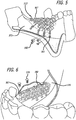
- an exemplary implantable device 500 is shown as disposed in a patient's mouth to replace a missing segment of the lower jaw (mandible) which may have been a result of any number of circumstances such as cancer, gun shot wound, or the like.
- the rig 513 incorporated with root-form implant 567" and abutments 670" is disposed on the mandible bone 16, after a portion of the gum has been excised and reflected.
- Fixating screws 560 are used to fixate the rig 513" on the jawbone.
- Bone graft substance 590 is placed in and around the rig similar to that describe in relation to FIGS. 13 and 14 .
- the rig 513" provides a scaffold where the bone graft will conduce bone.
- Membrane 620 (not shown) is placed on top of the rig (and the incorporated abutments") and the bone graft. The gum is sutured in place using sutures 625.
- crowns 549 are disposed on the abutments 670", all during the same surgical procedure.
- the rig will eventually fuse with the jawbone over time.
- the crowns 549 may be pre-disposed on the abutments 670" prior to the rig being disposed on the jawbone.
- the lower portion of the implant may have a sufficiently large surface area in order to provide the necessary affixation of the implant to the jawbone.
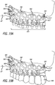
- an exemplary implantable device 500 is shown as disposed in a patient's mouth to replace missing teeth of a patient with severe to moderate bone loss on the edentulous upper jaw 16".
- Bone grafts may be used in combination with the method and/or device herein. Bone grafts may also be used before and/or after the method and/or device described herein. There are several types of bone grafts, any of which may be used at any time sequence or frame of time in reference to the present invention. Bone grafts may be used wherein the bone to be grafted to the jaw is taken, or harvested, from the patient's own body. The area where the bone is harvested from, known as the donor site, is usually the mouth or the hip. This is the patient's own bone and is very compatible with his/her body. Autografts are generally the best graft technique and usually result in the greatest regeneration of missing jawbone.
- Allografts are taken from human donors. Bone obtained in this manner undergoes rigorous tests and sterilization. The patient's body converts the donor bone into the patient's natural bone, thereby rebuilding his/her resorbed jawbone. Xenografts are harvested from animals. The animal bone, most commonly bovine (cow), is specially processed to make it biocompatible and sterile. It acts like a filler which in time the patient's body will replace with natural bone. After this replacement process is complete, dental implants may be placed to support the teeth. Alloplastic grafts are inert, man-made synthetic materials. The modern artificial joint replacement procedure uses metal alloplastic grafts. For bone replacement a man-made material that mimics natural bone is used.
- the patient's body may or may not replace the alloplastic graft with the patient's natural bone. In those cases where it is not replaced, it acts as a lattice or scaffold upon which natural bone is built. In either case, the end result is to create enough bone for the placement of dental implants.
- recombinant human bone morphogenetic protein e.g., available from Medtronic Corporation
- osteoblast bone forming cells
- Other types of bone grafting using recombinant DNA technology such as, for example, growth factors and/or morphogens may also be used.
- Root-form implants may be incorporated as part or parts of the method and/or device herein. Root form implant, when they are incorporated in the device or rig could be partially placed inside the present bone when the bone volume allows to aid in the primary retention and fixation of the device. Root-form implants may also be used in areas adjacent to where the device is placed before and/or after the method and/or device described herein. There are several types of root-form implants, any of which may be used at any time sequence or frame of time in reference to the present invention. Root-form implants may be the closest in shape and size to the natural tooth root. They are commonly used in wide, deep bone to provide a base for replacement of one, several or a complete arch of teeth.
- the healing period usually varies from patient to patient and can be of any time length.
- the healing period can be two weeks, one month, six weeks, two months, ten weeks, three months, fourteen weeks, four months, eighteen weeks, five months, twenty-two weeks, six months, twenty-six weeks, seven months, thirty weeks, eight months, thirty-four weeks, nine months, thirty-eight weeks, ten months, forty-two weeks, eleven months, forty-six weeks, and a year.
- Plate-form implants are usually used when the bone is so narrow that it may not be suitable for the root-form implant and the area is not suitable for bone grafting.
- the plate-form implant is flat and long so it can fit into the narrow jawbone. After application of anesthetic, the dentist will expose the area of the jawbone to be implanted and prepare the bone to accept the shape of the implant. The number of incisions depends upon the number of implants being placed. The implant is carefully set into place and the gums are closed with several stitches. Like root-form implants, there is usually a healing period for osseointegration, although some plate form implants are designed for immediate restoration.
- the plate form implant or implants could be incorporated as part or parts of the rig.
- the plate form could be implanted in the area adjacent to the area where the device is implanted before or after the device is implanted.
- the subperiosteal implant may be prescribed.
- the subperiosteal implant is custom made and designed to sit on top of the bone, but under the gums. There are two methods for its placement.
- the dentist will expose the jawbone and take an impression or model of the bone using special materials.
- This model is used by a dental laboratory to carefully create the custom implant to fit the patient's jaw.
- a second procedure is then carried out where the jawbone is exposed and the implant placed.
- the gums are closed with several stitches and replacement teeth are put into place.
- the dentist will order a special CAT scan of the patient's jawbone.
- a model of the jawbone is constructed. This model is used by a dental laboratory to fabricate the custom subperiosteal implant to fit the patient's jaw.
- a surgical procedure is then carried out where the jawbone is exposed and the implant placed. The gums are closed with several stitches and the replacement teeth are put into place.
Description
- This application claims the benefit of priority to U.S. Patent Application No.
13/335,371, filed December 22, 2011 - The present invention is generally related to implants for compensating bone loss in the mammalian body, and more particularly, and for example devices and methods for replacing or creating facial bone.
- Bone loss is a phenomenon that may occur for any number of reasons during one's life (whether human, mammal, or any other vertebrate). Dental implants are fixtures of metal, typically titanium alloy, which are surgically screwed into the jawbone, often for replacing missing teeth. In the case of a dental implant, the implant is an anchor for a naturally-appearing false tooth or a set of false teeth. The success rate of dental implants depends on where and how the implants are placed and their purpose. It is important that the subject has enough bone in the area of the missing tooth/teeth for the implants to be attached to. Implants are used to replace single, multiple or all teeth. Implants are increasingly being used to replace fixed bridges and removable partial or full dentures.
- For a patient who is missing one or more of his/her teeth, implants may well be an option for candidate as long as the patient has enough bone in the area of the missing tooth/teeth to facilitate the anchorage of the implants. If the patient does not have enough bone for this purpose, a bone graft may be necessary. Dental implants are alternatives to fixed bridge, a removable partial dentures or removable full dentures.
- The typical implant procedure is a surgical placement of the implant or implants in the patient's jawbone which requires a three to six months healing period before the implant restoration (crown) can be placed. During this healing time, the bone grows in and around the titanium implant creating a very strong support. Although the rejection or failure rate of dental implants is low, in the event such rejection happens, the implant is replaced with another implant of a slightly larger size or do bone graft and place another implant
- When missing one tooth, the cosmetic dentist may use a flipper to fill the space. A flipper is a false tooth to temporarily take the place of a missing tooth before the permanent crown is placed on the implant. A flipper can be attached via a wire or an acrylic base that fits on the roof of the mouth. Flippers are meant to be a temporary solution while awaiting the permanent crown to be placed on the implant(s).
- There are many implants available, each designed for a specific function. Most are made of titanium alloy, an inert metal which has been proven to be effective at fusing with living bone, a process known as osseointegration.
- Sometimes, when resorption has excessively reduced the jawbone, it can be rebuilt through modern bone grafting techniques. Bone grafts can build up or fill in jawbone defects allowing the placement of dental implants.
- In the single surgery method the dentist will order a special CAT scan of the patient's jawbone. Using the CAT scan data and advanced computer modeling techniques, a model of the jawbone is constructed. This model is used by a dental laboratory to fabricate the custom subperiosteal implant to fit the subject's jaw. A surgical procedure is then carried out where the jawbone is exposed and the implant placed. The gums are closed with several stitches and the replacement teeth are placed on the abutments of the subperiosteal implant.
- Despite the advances in dentistry and implant procedures, there is room for further improvement in providing enhanced devices and methods for more timely placement of implants, in particular dental implants.
-
US 5 433 607 discloses an implantable dental device as defined in the preamble ofclaim 1. - Aspects of the invention are recited in the independent claims and preferred features are recited in the dependent claims.>
- The present invention relates to a dental device and to a method for fabricating such a dental device in a patient's body. In an embodiment, the implantable device embodying features of the present invention include a body formed from a rig having a trabecular meshwork structure with shapes suitable for a particular anatomical area of interest. In an embodiment, the device is a dental implant serving as a platform for placement of dental crowns or bridges. In an embodiment, the present devices and methods enhance the growth of bone, as for example, the mandibular bone. In an embodiment, the growth is new bone growth where for any number of reasons, the original bone was either lost or never existent. Provided herein is an implantable device comprising a 3 dimensional trabecular meshwork structure having a length, a height, a width, a first end, and a second end, at least one fixating surface for receiving a fixating element for operatively attaching the rig to the bone and at least one cap receiving surface for receiving one or more caps thereon. In some embodiments of the device, the length of the structure is nominally defined by a distance between the first end and second end of the structure, and ranges from about 5 mm to about 200 mm. In some embodiments of the device, the height of the structure is nominally defined by a distance between a lower rim and an upper rim of the structure, and ranges from about 1 mm to about 60 mm. In some embodiments of the device, the structure is formed from a plurality of cell structures. In certain embodiments of the device, the plurality of cell structures comprises a matrix having a depth and height which ranges from about 1 to about 9 cells, and from about 9 to about 1 cell, respectively. In some embodiments of the device, each cell has an inner surface area ranging from about 50 microns to about 10 mm. In other embodiments of the device, the ratio of the total inner area of the cells to the total surface area of the structure ranges from about 10% to about 90%. In some embodiments of the device, the lower rim of the structure includes at least one bone fixation surface. In certain embodiments of the device, at least one cap receiving surfaces include at least one abutment receiving surface for receiving a crown thereof.
- Also disclosed is a method for implanting a device in a patient's body, comprising identifying a patient suitable for receiving an implant such as a dental implant, commissioning a three dimensional image of a target area of the patient's body for receiving the implant, commissioning a design of the implant using computer modeling, commissioning the construction of the implant using deposition method, and affixing the implant within the patient's body. In some embodiments of the method, the image is procured using CT scan. In other embodiments of the method, the implant is constructed using a 3D laser printing techniques by 3D Laser Sintering Printing. In certain embodiments of the method, the implant is constructed from a bio-compatible material. In some embodiments of the method, the bio-compatible material comprises at least one of titanium alloy or zirconium. In an embodiment, the implant material of the present invention is non-porous or substantially non-porous. In an embodiment, the surface of the implant is textured in areas where bone growth is desirable to maximize the surface between the bone and the rig. In an embodiment, where the abutment emerges through the soft tissue, the implant surface is smooth to minimize undesirable bacteria collection at the soft tissue level (e.g., gum level).
- In other embodiments of the method, the implant is a dental implant and the affixing of the implant within the patient's body comprises reflecting a gum of the patient to expose a bone area suitable for receiving the dental implant, disposing a dental implant on the bone area, the dental implant comprising a rig having a three (3) dimensional trabecular meshwork structure having a length, a height, a width, a first end, and a second end, at least one fixating surface for receiving a fixating element to operatively attach the rig to the patient and at least one cap receiving surface for receiving one or more caps thereon. In an embodiment the rig has a plurality of cells forming the meshwork and facilitating the fixation of the dental implant to the patient's bone. In certain embodiments, the method further comprises applying bone graft substance to the plurality of the cells. In some embodiments, the method further comprises disposing at least one permanent abutment on a pre-determined portion of the cap receiving surface fixating the gum in place, and disposing one or more caps on the at least one permanent abutment. In other embodiments of the method, disposing of the permanent abutment occurs during at least substantially the same surgical procedure as the disposing of the rig in the patient's mouth. In some embodiments of the method, disposing of the permanent abutment occurs in a substantially subsequent surgical procedure following the disposing of the rig in the patient's mouth after the passage of a period of time. In certain embodiments of the method, the subsequent surgical procedure comprises, disposing healing abutments onto the rig, and allowing passage of time before disposing the permanent abutment step.
- The rig being a three dimensional structure, includes several sides, surfaces, and/or ends, herein described relative to a patient's mouth once implanted therein. It should, however, be appreciated by those skilled in the art that such relative positional references are for ease of reference.
- In an embodiment, the rig includes a length, a height, a width, a front end or edge, and a back end or edge, an outer surface, and an inner surface. These nouns describing the various parts of the device are used for ease of reference and are as defined by the present inventor. By way of example, as used herein and as positioned in the lower jaw of a patient's mouth, the front end refers to the side closest to the patient's front teeth; back end refers to the end opposite the front end; outer surface refers to the side of the device facing the cheek of the patient; the inner surface refers to the side of the device opposite the outer surface; the length refers to the dimension extending from the front end (toward the front tooth) to the back end (toward the molar tooth); height refers to the dimension extending vertically from the surface adjacent the lower jaw toward the roof of the mouth; width refers to the dimension extending between the outer surface and the inner surface. It should be noted that although the present invention is being described relevant to a dental implant and process for making and using the same, that such devices and methods are not limited to the dental applications and may be used in any other anatomical structure suffering from some, substantial, or complete bone decay or bone loss, or insufficient bone mass.
- The length of the structure may nominally be defined by a distance between the first end and second end (or rim) of the structure, and ranges from any amount to fit within a patient's mouth. For example, the range of length may be from about 5 mm to about 200 mm. In other embodiments of the device, the height of the structure may be nominally defined by a distance between a lower rim and an upper rim (or lower edge and upper edge) of the structure, and ranges from any amount to fit within a patient's mouth. For example, the range of height may be from about 1 mm to about 60 mm. In some embodiments of the device, the structure may be formed from a plurality of cell structures. In certain embodiments of the device, the plurality of cell structures comprises a matrix having a depth and height which ranges from any amount to fit within a patient's mouth. For example, the range of depth and height may be from about 1 to about 9 cells. The range of depth and height may also, for example, range from about 9 to about 1 cell. In other embodiments of the device, each cell has an inner surface area ranging from any amount to fit within a patient's mouth. For example, the inner surface area range may be from about 50 microns to about 10 mm. In other embodiments of the device, the ratio of the total inner area of the cells to the total surface area of the structure may range from any amount to fit within a patient's mouth. For example, the ratio of the total inner area of the cells to the total surface area of the structure may range from about 10% to about 90%.
- The matrix, having a plurality of cell structures, may also be referred to as a rig, platform, device, implant, mesh network, meshwork, scaffolding, structure, metallic bridge, plate, or combinations thereof. The matrix may also be made of any type of suitable material.
- The implant includes at least one bone fixation feature for being operatively attachable to a bone surface of the patient. The implantable device, in an embodiment, includes at least one cap (or similar coverings including crowns) receiving surface for receiving one or more caps (and/or crowns or similar objects) thereon.
- The healing period for any method or procedure described herein may vary from patient to patient and can be of any length of time. For example, the healing period can be two weeks, one month, six weeks, two months, ten weeks, three months, fourteen weeks, four months, eighteen weeks, five months, twenty-two weeks, six months, twenty-six weeks, seven months, thirty weeks, eight months, thirty-four weeks, nine months, thirty-eight weeks, ten months, forty-two weeks, eleven months, forty-six weeks, and a year.
- In an embodiment, the implants and methods using the same, provide for a single or a multi-step process (e.g., periods of delay in between treatments and/or separate surgical procedures). In an embodiment, the implants and methods embodying features of the present invention provide for relatively immediate placement of the implant configured for integration with the patient's bone within the body, and in particular, in areas having bone deficiency. In an embodiment, the implants and methods embodying features of the present invention comprise a multi-step process where there are periods of delay and healing in between separate surgical procedures.
- By way of example, in the case of the rig being implanted in the lower jaw of the patient, at least the lower edge, surface, or rim will include the bone fixation surface for affixation of the device to the lower jaw of the patient. The rig, at its front and/or back ends, may also include at least one or more bone fixation surface.
- The rig may include, at the top edge or surface or rim (as for example the edge opposite the lower jaw bone and directed toward the roof of the mouth), a cap (or crown) receiving surface. The cap-receiving surface is configured for securely receiving thereon a cap or similar device, such as a dental crown.
- In an embodiment, the rig at the upper surface includes at least one abutment surface, disposable between the rig and the cap, for receiving the dental cap thereon. The at least one abutment surface may be splinted rigidly as one piece with the rig or attachable to the rig by suitable means and structures including but not limited to adhesives, male/female attachments, screws and the like.
- The rig may be custom designed using any number of suitable means such as three dimensional (3D) modeling software to fit the particular anatomical area of interest such as an edentulous area of the specific patient. Such design may be carried out upon imaging of the patient's anatomical area of interest using techniques and tools such as CT scan of the jaw. Upon completion of the design of the rig, the virtual design may be transformed into a physical structure/rig by way of suitable techniques such as 3D Laser Sintering printers, such as those available from Materialise, 3D systems.
- In some embodiments of the method, the bio-compatible material may be of any type, percentage composition, combination, purity, strength and the like. The bio-compatible material may be of general biocompatibility, immunological biocompatibility, or bio-energetic biocompatibility. Any type of biocompatible material may be used, for example, composite filling, porcelain, aluminum oxide, gallium alloys, non-allergenic or non-toxic metals, amalgam, alloy, direct composite, indirect composite inlay/onlay, porcelain inlay/onlay, gold inlay/onlay, titanium inlay/onlay, gold or silver, non-precious alloys, zirconium oxide, titanium, and combinations thereof.
- In an embodiment, the rig includes cavities or cells defined by a plurality of girders which in turn form a truss. The bone matter may fill in the cavities over time. In an embodiment, the rig is configured to include a relatively higher cavity or cell surface area to implant surface area for enhanced subsequent integration with the patient's bone. In an embodiment, the rig may be hyroxyapatite coated, plasma sprayed, or etched (e.g., chemically etched) to provide the increased bone/implant surface.
- Rigs constructed according to the present invention, provide for enhanced bone conduction. The rigs employed as scaffolding structures, allow autogenous, allograft, and or xenograft bone graft substance or bone morphogenic protein to grown in and around the rig to replace the missing bone.
- In an embodiment, the rig may be affixed to the bone, e.g., jaw bone, by suitable means such as screws, wires, intrusions into the jaw bone by drilling specific osteotomies to allow certain parts of the rig to endosseously integrate with the patient's body. In an embodiment, the rig will, in time, become a part of the patient's body as bone grows inside and around the rig's mesh-like structure.
- The implants embodying features of the present invention may be implanted as a single stage implant procedure. In an embodiment, the abutments (or abutment surfaces) can be splinted as one part of the rig. Transitional or permanent prosthesis may also be disposed on the same day of the procedure.
- In an embodiment, the rig may be placed initially in the patient's mouth, separated, from permanent abutments. In this embodiment, the rig may be placed in the mouth along with healing screws. This configuration may allow the bone to grow and integrate with the rig and to be covered at least substantially with soft tissue. Thereafter, after passage of sufficient time (e.g., 6 months), during the next stage of the procedure, healing screws are removed and healing abutments are placed in the rig to allow the placement of permanent abutments and prosthesis at, preferably, a later time.
- The rig may be covered with resorbable or non-resorbable membrane, connective tissue, pericardium membrane, alloderm graft, or any other suitable material held in soft tissue coverage and to allow for a sufficiently effective protection of the rig and the bone graft.
- As indicated earlier, the rig may be used in other implant reconstructive procedures in other suitable areas of the jaw or the anatomy all together, where bone will be necessary or useful to grow in certain shape, form, and/or volume. By way of example and not limitation, such other modalities include orthopedics, plastic surgery, oral and maxillofacial surgery, ENT (ear, nose, throat), or any other anatomical area and procedure which may benefit from the devices and methods of the present invention.
- The above and other features of the present invention, which will become more apparent as the description proceeds, are best understood by considering the following Detailed Description in conjunction with the accompanying drawings, wherein like characters represent like parts throughout the several views.
- Non-limiting and non-exhaustive features of the present invention are described with reference to the following figures, wherein like reference numerals refer to like parts throughout the various figures.
-
FIG. 1A is a simplified illustration of a patient undergoing imaging procedure. -
FIG. 1B is a simplified illustration of the process for capturing the image of the patient's mouth and fabricating an implantable device having the features of the present invention. -
FIGS. 2A and 2B are simplified illustrations of an implantable device embodying features of the present invention disposed within a patient's mouth. -
FIG. 3 is a simplified illustration of a process for exposing a patient's jaw bone by reflecting the gums and oral mucosa covering the bone. -
FIG. 4 is a simplified illustration of a step in a process for disposing an implantable device embodying features of the present invention in a patient's mouth, showing the disposal of a surgical guide in the patient's mouth. -
FIGS. 5 and 6 are a simplified illustrations of steps in a process for disposing an implantable device embodying features of the present invention in a patient's mouth, showing the disposal of a device in the patient's mouth. -
FIG. 7 is a simplified illustration of a step in a process for disposing an implantable device embodying features of the present invention in a patient's mouth, showing the application of bone graft substance onto and/or within cavities of the device. -
FIG. 8 is a simplified illustration of a step in a process for disposing the device ofFIG. 7 in a patient's mouth, showing the suturing of the flap. -
FIG. 9 is a simplified illustration of a step in a process for implanting the device ofFIG. 8 in a patient's mouth, showing the removal of healing screws and placement of healing abutments. -
FIG. 10 is a simplified illustration of a step in a process for implanting the device ofFIG. 9 in a patient's mouth, showing healing abutments in place. -
FIG. 11 is a simplified illustration of a step in a process for implanting the device ofFIG. 10 in a patient's mouth, showing the removal of healing abutments. -
FIG. 12 is a simplified illustration of a step in a process for implanting the device ofFIG. 11 in a patient's mouth, showing the placement of crowns. -
FIG. 13 is a simplified illustration of a step in a process for disposing an implantable device embodying features of the present invention in a patient's mouth, showing the application of bone graft substance onto and/or within cavities of the device, with abutments being integrated with the rig. -
FIG. 14 is a simplified illustration of a step in a process for implanting the device ofFIG. 13 in a patient's mouth, showing the suturing of the soft tissue flap. -
FIGS. 15A and 15B are simplified side views of steps in a process for replacing bone and restoring function when the whole body of mandible or whole segment of the mandible is missing due to various reasons such as cancer, gunshot, facial trauma, etc. -
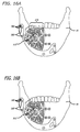
FIGS. 16A and 16 B are front views of illustrations ofFIGS. 15A and 15B . -
FIGS. 17A and 17 B are top views of illustrations ofFIGS. 15A and 15B . -
FIGS. 18A andl8B are simplified front views of steps in a process for restoring the aesthetic and function in atrophic jaw where all the teeth are missing. -
FIGS. 19A and 19 B are side views of illustrations ofFIGS. 18A and 18B . -
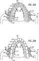
FIGS. 20A and 20 B are top (occlusal) views of illustrations ofFIGS. 18A and 18B . - The present invention relates to devices and methods for implanting an implantable device in a patient's body. In an embodiment, the device is a dental implant serving as a platform for placement of dental crowns and/or caps and/or fixed or removable prosthesis.
- Features of an exemplary device and method for implanting the same, after it has been fabricated as described earlier, will be explained in reference to the following figures. It should be noted that either or both process and apparatus elements may be intended when referring to the following figures.
- Now referring to
FIGS. 1A and1B , a patient 10 is identified needing a dental implant. In an embodiment, the patient suffers from total or substantial bone loss in the jaw. The physician commissions a threedimensional image 11 of the patient's anatomical area of interest using a3D scanning tool 130. The anatomical area of interest may be the patient's mouth requiring such implant. The image and related information may be captured on adata storage 160, either local or remote to the scanning tool. The image and related information may be displayed on adisplay 190 with akeyboard 210 providing the means for data and instructional communication between an operator and thescanning tool 130. - Once the image has been scanned, the image is used to create a virtual implantable device. The commissioning and design, as for example shown in 13 of
FIG. 1B , of the suitable implant may include the use of any appropriate tool including computer modeling. - The fabrication of the implant is then commissioned, as for example shown in 15 of
FIG. 1B . The virtual implantable device is thereafter used to create a 3D implantable device 500 (as shown inFIGS. 2A and 2B ), using techniques such as 3D laser printing. The implant may be fabricated using other suitable methods, including, but not limited to, deposition or casting. As shown, a3D laser printer 17 used to fabricate theimplantable device 500. - 3D printing is a form of additive manufacturing technology where a three dimensional object is created by laying down successive layers of material. 3D printers are generally faster, more affordable and easier to use than other additive manufacturing technologies. 3D printers offer product developers the ability to print parts and assemblies made of several materials with different mechanical and physical properties in a single build process. Advanced 3D printing technologies yield models that can serve as product prototypes. Using techniques and equipment such as 3D laser printers, great resolution, accuracy, and precision in the fabrication of the desired object can be obtained.
- Thereafter, after appropriate examination of the fabricated implant, the implant using methods embodying the present invention will be affixed within the patient, e.g., patient's mouth.
- Now referring to
FIGS. 2A and 2B , an exemplaryimplantable device 500 is shown as disposed in a subject's mouth. - In an embodiment, the
implantable device 500 includes a trabecular meshwork structure such as arig 513 having alength 516, aheight 519, awidth 521, a front edge (or rim) 524, and backedge 527, an outer edge orsurface 535, and an inner edge orsurface 533. Therig 513 includes pluralities of girder-like structures 514 defining a plurality ofcavities 515 therebetween. It should be noted that the term girder-like is not intended to be limited to elements which may form traditional triangular truss structures or elements and the network may take any suitable form or geometry as for example, the truss-like structures having curved elements such as struts in a cardiovascular stent. It should further be noted that the nouns describing the various parts of the device are used for ease of reference and are as defined by the present inventor. By way of example, as used herein and as positioned in thelower jawbone 16 of a patient's mouth, thefront edge 524 refers to the side closest to the patient's lips; backedge 527 refers to the edge opposite the front edge;outer edge surface 535 to the side of the device facing the cheek of the patient; theinner surface 533 refers to the side of the device opposite the outer surface; thelength 516 refers to the dimension extending from the front edge (e.g., front teeth 525) to the back edge 527 (toward the molar tooth);height 519 refers to the dimension extending vertically in the direction from the lower jaw toward the roof of the mouth;width 521 refers to the dimension extending between the outer surface and the inner surface. It should be appreciated, however, that the devices of the present invention are not limited by these nouns and are adaptable for use in any suitable part of the mount or other anatomical areas of the patient. - The
implant 500 includes at least onebone fixation feature 540 for being operatively attachable to abone surface 542 of the patient, and at least one cap (or similar coverings including crowns) receiving feature 546 (see for example,FIG. 13 ) for receiving one or more caps 549 (and/or crowns) thereon (SeeFIG. 14 ). As shown inFIGS. 2A and 2B , the at least onebone fixation feature 540 is configured for being fixedly attachable to thelower jawbone 16 of the patient and the at least onecap receiving feature 546 is opposite the at least onefixation feature 540. - Now referring to
FIGS. 3 and 4 , agum 522 is incised by way of anincision 555 and reflected 558 exposing thejawbone 16. Asurgical guide 561 is positioned on the teeth.Osteotomies 564 are drilled through thesurgical guide 561 into thejawbone 16. Thesurgical guide 561 is thereafter removed. - As shown in
FIGS. 5 and 6 , a rig 513', such as a titanium rig, and incorporated with root-form implant 567 is then placed on thejawbone 16. Fixatingelements 560, such as fixating screws, are used to fixate the rig 513' onto thejawbone 16 on either or both the front and back of the jawbone. The fixating may occur in one or more places along the jawbone as appropriate. By way of example, one or more fixating screws 560 may be positioned throughfixation ports 561 inouter surface 573 of the jawbone, on theinner surface 576 of the jawbone, front-portion of the jawbone, and/or backside-portion of the jawbone, or any other portion as may be necessary. One or more healing elements such as healing screws 579 are positioned in the rig 513'. As shown inFIG. 6 , a plurality ofhealing screws 579 are positioned on thetop surface 582 of the rig (or the bottom surface if the rig were disposed on the upper jaw). The rig is secured in place as can be seen fromFIGS. 5 and 6 , on both the outer and the inner potions of the jawbone. -
Bone graft substance 590, as can be seen inFIG. 7 , is placed in and around the rig using appropriate tools such assurgical spatula 593. In the embodiment, as shown, thebone graft substance 590 is particularly placed inside the cavities/cells 515 formed by thegirders 514. As shown inFIG. 7 , the bone graft substance covers at least substantially the inside and the outside of the rig. The rig provides scaffold, where the bone graft will conduce bone growth.Membrane 620 is placed over, at least a substantial portion, of the rig to cover the rig and the bone graft substance. In the embodiment shown, the membrane at least substantially covers the healing screws 579. Thegum 522 is then sutured inplace using sutures 625 or other similar elements. - Now referring to
FIGS. 9 and 10 , after passage of suitable period of time, for example 6 months, the healing screws 579 are exposed and removed.Healing abutments 630 are placed on the rig 513' where the healing screws 579 were previously located. - Now referring to
FIGS. 11 and 12 , after the passage of suitable period of time, for example 1 month, thehealing abutments 630 are removed andpermanent abutments 670 andcrowns 549 are placed onto the rig 513'. Abutment fixating screws 673, may be used to secure thepermanent abutments 670 onto therig 513. The sutures may also be removed at this time (or the sutures may of the disintegratable or resorbable type). - In an exemplary embodiment, similar to the method generally described above, features of which are generally shown in
FIGS. 13 and 14 , after the completion of steps generally shown inFIG. 4 , arig 513" incorporated with root-form implant 567" andabutments 670" is placed on thejawbone 16. Fixatingscrews 560 are used to fixate therig 513" on the jawbone.Bone graft substance 590 is placed in and around the rig similar to that describe in relation toFIG. 7 . Therig 513" provides a scaffold where the bone graft will conduce bone.Membrane 620 is placed on top of the rig (and the incorporated abutments") and the bone graft. The gum is sutured inplace using sutures 625. Finally thecrowns 549 are disposed on theabutments 670", all during the same surgical procedure. The rig will eventually fuse with the jawbone over time. - Now referring to
FIGS. 15A, 15B ,16A, 16B ,17A and 17B , an exemplaryimplantable device 500 is shown as disposed in a patient's mouth to replace a missing segment of the lower jaw (mandible) which may have been a result of any number of circumstances such as cancer, gun shot wound, or the like. - As shown, the
rig 513", incorporated with root-form implant 567" andabutments 670", is disposed on themandible bone 16, after a portion of the gum has been excised and reflected. Fixatingscrews 560 are used to fixate therig 513" on the jawbone.Bone graft substance 590 is placed in and around the rig similar to that describe in relation toFIGS. 13 and 14 . Therig 513" provides a scaffold where the bone graft will conduce bone. Membrane 620 (not shown) is placed on top of the rig (and the incorporated abutments") and the bone graft. The gum is sutured inplace using sutures 625. Finally thecrowns 549 are disposed on theabutments 670", all during the same surgical procedure. The rig will eventually fuse with the jawbone over time. In the alternative, thecrowns 549 may be pre-disposed on theabutments 670" prior to the rig being disposed on the jawbone. In the embodiment shown, the lower portion of the implant may have a sufficiently large surface area in order to provide the necessary affixation of the implant to the jawbone. - Now referring to
FIGS. 18A, 18B ,19A, 19B ,20A and 20B , an exemplaryimplantable device 500 is shown as disposed in a patient's mouth to replace missing teeth of a patient with severe to moderate bone loss on the edentulousupper jaw 16". - Bone grafts may be used in combination with the method and/or device herein. Bone grafts may also be used before and/or after the method and/or device described herein. There are several types of bone grafts, any of which may be used at any time sequence or frame of time in reference to the present invention. Bone grafts may be used wherein the bone to be grafted to the jaw is taken, or harvested, from the patient's own body. The area where the bone is harvested from, known as the donor site, is usually the mouth or the hip. This is the patient's own bone and is very compatible with his/her body. Autografts are generally the best graft technique and usually result in the greatest regeneration of missing jawbone.
- Allografts are taken from human donors. Bone obtained in this manner undergoes rigorous tests and sterilization. The patient's body converts the donor bone into the patient's natural bone, thereby rebuilding his/her resorbed jawbone. Xenografts are harvested from animals. The animal bone, most commonly bovine (cow), is specially processed to make it biocompatible and sterile. It acts like a filler which in time the patient's body will replace with natural bone. After this replacement process is complete, dental implants may be placed to support the teeth. Alloplastic grafts are inert, man-made synthetic materials. The modern artificial joint replacement procedure uses metal alloplastic grafts. For bone replacement a man-made material that mimics natural bone is used. Most often it is a form of calcium phosphate. Depending on how it is made, it may be resorbable or non-resorbable. That is, the patient's body may or may not replace the alloplastic graft with the patient's natural bone. In those cases where it is not replaced, it acts as a lattice or scaffold upon which natural bone is built. In either case, the end result is to create enough bone for the placement of dental implants. Recently, recombinant human bone morphogenetic protein (e.g., available from Medtronic Corporation) has been used to create bone by inducing the stem cells to differentiate to osteoblast (bone forming cells) to form new bone. Other types of bone grafting using recombinant DNA technology such as, for example, growth factors and/or morphogens may also be used.
- Root-form implants may be incorporated as part or parts of the method and/or device herein. Root form implant, when they are incorporated in the device or rig could be partially placed inside the present bone when the bone volume allows to aid in the primary retention and fixation of the device. Root-form implants may also be used in areas adjacent to where the device is placed before and/or after the method and/or device described herein. There are several types of root-form implants, any of which may be used at any time sequence or frame of time in reference to the present invention. Root-form implants may be the closest in shape and size to the natural tooth root. They are commonly used in wide, deep bone to provide a base for replacement of one, several or a complete arch of teeth. After application of anesthetic, the dentist will expose the area of the jawbone to be implanted and prepare the bone to accept the implant. The number of incisions and bone preparations depends upon the number of implants (and teeth) being placed. The implant is carefully set into place and the gums are closed with several stitches. The healing period usually varies from patient to patient and can be of any time length. For example, the healing period can be two weeks, one month, six weeks, two months, ten weeks, three months, fourteen weeks, four months, eighteen weeks, five months, twenty-two weeks, six months, twenty-six weeks, seven months, thirty weeks, eight months, thirty-four weeks, nine months, thirty-eight weeks, ten months, forty-two weeks, eleven months, forty-six weeks, and a year.. During this time, osseointegration occurs. The bone grows in and around the implant creating a strong structural support. In fact, this bond can be even stronger than the original tooth. When healing is complete, the implant is uncovered and an extension or abutment is attached to it. Now the implant and abutment act as a solid unit ready to support the new tooth or teeth.
- Plate-form implants are usually used when the bone is so narrow that it may not be suitable for the root-form implant and the area is not suitable for bone grafting. The plate-form implant is flat and long so it can fit into the narrow jawbone. After application of anesthetic, the dentist will expose the area of the jawbone to be implanted and prepare the bone to accept the shape of the implant. The number of incisions depends upon the number of implants being placed. The implant is carefully set into place and the gums are closed with several stitches. Like root-form implants, there is usually a healing period for osseointegration, although some plate form implants are designed for immediate restoration. The plate form implant or implants could be incorporated as part or parts of the rig. The plate form could be implanted in the area adjacent to the area where the device is implanted before or after the device is implanted.
- With very advanced jawbone resorption there may not be enough bone width or height for the root-form or plate-form implant. In these cases the subperiosteal implant may be prescribed. The subperiosteal implant is custom made and designed to sit on top of the bone, but under the gums. There are two methods for its placement.
- In the dual surgery method, after application of anesthetic, the dentist will expose the jawbone and take an impression or model of the bone using special materials. This model is used by a dental laboratory to carefully create the custom implant to fit the patient's jaw. A second procedure is then carried out where the jawbone is exposed and the implant placed. The gums are closed with several stitches and replacement teeth are put into place.
- In the single surgery method the dentist will order a special CAT scan of the patient's jawbone. Using the CAT scan data and advanced computer modeling techniques, a model of the jawbone is constructed. This model is used by a dental laboratory to fabricate the custom subperiosteal implant to fit the patient's jaw. A surgical procedure is then carried out where the jawbone is exposed and the implant placed. The gums are closed with several stitches and the replacement teeth are put into place.
- The foregoing disclosure of the exemplary embodiments has been presented for purposes of illustration and description. It is not intended to be exhaustive or to limit the invention to the precise forms disclosed. Many variations and modifications of the embodiments described herein will be apparent to one of ordinary skill in the art in light of the above disclosure.
- Further, in describing representative embodiments, the specification may have presented methods and/or processes as a particular sequence of steps. However, to the extent that the methods or processes do not rely on the particular order of steps set forth herein, the methods or processes should not be limited to the particular sequence of steps described. As one of ordinary skill in the art would appreciate, other sequences of steps may be possible. Therefore, the particular order of the steps set forth in the specification should not be construed as limitations on the claims.
- While the invention is susceptible to various modifications, and alternative forms, specific examples thereof have been shown in the drawings and are herein described in detail. It should be understood, however, that the invention is not to be limited to the particular forms or methods disclosed, but to the contrary, the invention is to cover all modifications, equivalents and alternatives falling within the scope of the appended claims.
Claims (12)
- An implantable dental device (500) for implanting within a subject's mouth, comprising:a 3 dimensional trabecular meshwork structure (513) configured to promote bone growth and having a plurality of interconnected cells configured for receiving bone graft material (590) therein, the structure having a length (516), a height (519) coextending substantially along a vertical axis extending between the mandible and maxilla, a width (521) coextending substantially along a horizontal axis extending between facial and lingual sides, a first end (524), and a second end (527), the structure configured for permanent placement within the patient's mouth; characterised by a plurality of root-form implants (567, 567") formed integral with the meshwork structure (513), the root-form implants (567, 567") having a substantially cylindrical body, at least a portion of the cylindrical body of at least one of the root-form implants configured for at least partial penetration within a jaw bone (16);at least one fixating surface (561) located substantially on the structure for receiving at least one fixating element (560) for operatively and fixedly attaching the structure to the patient's jawbone (16); anda plurality of prosthesis receiving surfaces, each of the prosthesis receiving surfaces disposed adjacent a corresponding root-form implant (567, 567") for receiving a corresponding number of prostheses (549) thereon.
- The device (500) of Claim 1, wherein the at least one fixating surface is located on a surface of the structure, the fixating surface being substantially perpendicular to the vertical axis.
- The device (500) of Claim 2, wherein at least some of the plurality of the prosthesis receiving surfaces include a corresponding abutment receiving surface for receiving an abutment thereon.
- The device of Claim 2 or 3, wherein the structure (513) resembles a scaffold resulting, at least in part, in guided bone growth which is formed subsequent to the implantation, formed within at least a substantial portion of the plurality of cells.
- The device of Claim 3, comprising at least one abutment, wherein the plurality of abutment receiving surfaces and at least one of the plurality of root-form implants (567, 567") are incorporated into the structure.
- The device (500) of Claim 1 or 2, wherein at least a portion of the interconnected cells form a plurality of vertically aligned cells.
- The device of Claim 6, comprising at least one abutment, wherein the at least one abutment and at least one of the plurality of root-form implants (567, 567") are incorporated into the structure; and the at least one fixating surface for receiving the fixating element is configured to accommodate a threaded fixating element which upon engagement is substantially perpendicular to a surface of the structure.
- A method for fabricating a dental device (500) implantable in a patient's mouth according to any one of Claims 1 through 7, comprising:identifying a patient suitable for receiving a dental implant according to any one of Claims 1 through 7;commissioning a three dimensional image of the patient's mouth;commissioning a design of the implant using computer modeling; andcommissioning the construction of the implant using deposition method.
- The method of Claim 8, wherein the image is procured using CT scan.
- The method of any one of Claims 8 or 9, wherein the implant is constructed using a 3D laser printing techniques by 3D Laser Sintering Printing.
- The method of any one of Claims 8 through 10 wherein the implant is constructed from a bio-compatible material.
- The method of Claim 11, wherein the bio-compatible material comprises at least one of titanium alloy or zirconium.
Priority Applications (1)
| Application Number | Priority Date | Filing Date | Title |
|---|---|---|---|
| EP17181413.0A EP3263065A1 (en) | 2011-12-22 | 2012-12-20 | Devices and methods for enhancing bone growth |
Applications Claiming Priority (2)
| Application Number | Priority Date | Filing Date | Title |
|---|---|---|---|
| US13/335,371 US8485820B1 (en) | 2011-12-22 | 2011-12-22 | Devices and methods for enhancing bone growth |
| PCT/US2012/070886 WO2013096592A1 (en) | 2011-12-22 | 2012-12-20 | Devices and methods for enhancing bone growth |
Related Child Applications (1)
| Application Number | Title | Priority Date | Filing Date |
|---|---|---|---|
| EP17181413.0A Division EP3263065A1 (en) | 2011-12-22 | 2012-12-20 | Devices and methods for enhancing bone growth |
Publications (3)
| Publication Number | Publication Date |
|---|---|
| EP2793734A1 EP2793734A1 (en) | 2014-10-29 |
| EP2793734A4 EP2793734A4 (en) | 2015-08-26 |
| EP2793734B1 true EP2793734B1 (en) | 2017-07-19 |
Family
ID=48654901
Family Applications (2)
| Application Number | Title | Priority Date | Filing Date |
|---|---|---|---|
| EP17181413.0A Withdrawn EP3263065A1 (en) | 2011-12-22 | 2012-12-20 | Devices and methods for enhancing bone growth |
| EP12859870.3A Not-in-force EP2793734B1 (en) | 2011-12-22 | 2012-12-20 | Dental device for enhancing bone growth |
Family Applications Before (1)
| Application Number | Title | Priority Date | Filing Date |
|---|---|---|---|
| EP17181413.0A Withdrawn EP3263065A1 (en) | 2011-12-22 | 2012-12-20 | Devices and methods for enhancing bone growth |
Country Status (12)
| Country | Link |
|---|---|
| US (4) | US8485820B1 (en) |
| EP (2) | EP3263065A1 (en) |
| JP (1) | JP2015507491A (en) |
| KR (1) | KR20140113982A (en) |
| CN (1) | CN103997985A (en) |
| AU (1) | AU2012358904A1 (en) |
| BR (1) | BR112014015268A2 (en) |
| CA (1) | CA2859662A1 (en) |
| IL (1) | IL233235A0 (en) |
| IN (1) | IN2014CN04602A (en) |
| MX (1) | MX2014007503A (en) |
| WO (1) | WO2013096592A1 (en) |
Families Citing this family (78)
| Publication number | Priority date | Publication date | Assignee | Title |
|---|---|---|---|---|
| US9861482B2 (en) * | 2008-08-26 | 2018-01-09 | Andy Boiangiu | Dental bone implant and implant method |
| WO2012118843A1 (en) * | 2011-02-28 | 2012-09-07 | Tissue Regeneration Systems, Inc. | Modular tissue scaffolds |
| CN104135963B (en) * | 2011-12-23 | 2017-06-09 | 奥齿泰有限责任公司 | Tooth film |
| US20150335432A1 (en) * | 2012-02-09 | 2015-11-26 | Osseous Technologies Of America | Biocompatible containment member for bone augmentation surgery made of processed natural membrane from an animal donor |
| US9539069B2 (en) | 2012-04-26 | 2017-01-10 | Zimmer Dental, Inc. | Dental implant wedges |
| US9554877B2 (en) * | 2012-07-31 | 2017-01-31 | Zimmer, Inc. | Dental regenerative device made of porous metal |
| US20140038132A1 (en) * | 2012-07-31 | 2014-02-06 | Zimmer Trabecular Metal Technology, Inc. | Dental regenerative device made of porous metal |
| US10278789B2 (en) | 2013-03-14 | 2019-05-07 | National Dentex, Llc | Bone foundation guide system and method |
| US10405945B2 (en) | 2013-03-14 | 2019-09-10 | National Dentex, Llc | Bone foundation guide and method of use |
| US10307226B2 (en) | 2013-03-14 | 2019-06-04 | National Dentex, Llc | Bone foundation guide and method of use |
| US10398530B2 (en) | 2013-03-14 | 2019-09-03 | National Dentex, Llc | Bone foundation guide system and method |
| US10639129B2 (en) | 2013-03-14 | 2020-05-05 | National Dentex, Llc | Bone foundation guide system and method |
| US20160250002A1 (en) * | 2013-10-15 | 2016-09-01 | Marvin Cota | One Piece Custom Made Dental Device For Holding Multiple Teeth |
| US9545302B2 (en) | 2013-11-20 | 2017-01-17 | Dermagenesis Llc | Skin printing and auto-grafting |
| CN104665913B (en) | 2013-11-26 | 2017-06-06 | 财团法人工业技术研究院 | Bionic fixing device and pulling-out device thereof |
| CN104665906B (en) | 2013-11-26 | 2017-09-08 | 财团法人工业技术研究院 | Bionic fixing device |
| CN104665905B (en) | 2013-11-26 | 2018-04-06 | 财团法人工业技术研究院 | Bionic fixing device |
| CN103637862B (en) * | 2013-12-18 | 2015-12-23 | 北京爱康宜诚医疗器材股份有限公司 | Jawbone recovery support |
| US10688726B2 (en) * | 2014-03-04 | 2020-06-23 | Royal Melbourne Institute Of Technology | Method for producing a customised orthopaedic implant |
| ES2544904B1 (en) * | 2014-03-04 | 2016-07-07 | Francisco Javier RUIZ GINER | DENTAL ARTIFICIAL GRAFT |
| US11628001B2 (en) | 2014-03-11 | 2023-04-18 | Ohio State Innovation Foundation | Methods, devices, and manufacture of the devices for musculoskeletal reconstructive surgery |
| JP2016033940A (en) * | 2014-07-31 | 2016-03-10 | 株式会社東芝 | Gas isolation transformer |
| JP2016033959A (en) * | 2014-07-31 | 2016-03-10 | 株式会社東芝 | On-load tap switcher, and changeover switch for on-load tap switcher |
| US9566142B2 (en) * | 2014-10-24 | 2017-02-14 | Alfredo Villa | Dental prosthesis for cattle |
| TWI548429B (en) | 2014-11-07 | 2016-09-11 | 財團法人工業技術研究院 | Medical composite material method for fabricating the same and applications thereof |
| US10751100B2 (en) | 2014-12-17 | 2020-08-25 | Medartis Holding Ag | Bone screws and surgical sets comprising bone screws |
| WO2016095978A1 (en) | 2014-12-17 | 2016-06-23 | Medartis Holding Ag | Bone plate, surgical sets and reconstruction sets |
| EP3087954B1 (en) * | 2015-04-27 | 2019-01-30 | Peter Kessler | Jaw bone transplant arrangement |
| WO2016191393A1 (en) | 2015-05-22 | 2016-12-01 | Surgical Alternatives | Joint or segmental bone implant for deformity correction |
| US10449017B2 (en) * | 2015-06-08 | 2019-10-22 | Cadskills Bvba | Subperiosteal jaw implant |
| CA2989570C (en) * | 2015-06-18 | 2021-06-15 | Jean Robichaud | Method and system for generating a model of a subperiosteal dental implant device and customized implant head |
| WO2016210184A1 (en) | 2015-06-25 | 2016-12-29 | Buck Medical Research Ltd. | Orthopaedic or biologic support structure, methods of making and methods of use |
| US10363116B2 (en) | 2015-07-07 | 2019-07-30 | Align Technology, Inc. | Direct fabrication of power arms |
| DE102015215587A1 (en) | 2015-08-14 | 2017-02-16 | Nt-Trading Gmbh & Co. Kg | Method for producing a bone replacement piece |
| KR20180098230A (en) | 2015-10-23 | 2018-09-03 | 내셔널 덴텍스 엘엘씨 | Bone base guide system and method |
| US10898332B2 (en) * | 2015-11-24 | 2021-01-26 | Ossdsign Ab | Bone implants and methods for correcting bone defects |
| TWI587847B (en) | 2015-12-07 | 2017-06-21 | 財團法人工業技術研究院 | Implant device for osseous integration |
| DE102015122800B3 (en) * | 2015-12-23 | 2017-05-11 | Karl Leibinger Medizintechnik Gmbh & Co. Kg | Bone structure adapted molded implant with socket and associated manufacturing process |
| CN106994054A (en) * | 2016-01-22 | 2017-08-01 | 郑荣川 | A kind of new-type subperiosteum implant preparation method |
| AU2017211010B2 (en) * | 2016-01-28 | 2021-05-20 | DePuy Synthes Products, Inc. | Splitting attachment for graft containment cage |
| JP6976956B2 (en) * | 2016-01-28 | 2021-12-08 | デピュイ・シンセス・プロダクツ・インコーポレイテッド | Spiral bone graft storage cage |
| KR101774149B1 (en) | 2016-03-23 | 2017-09-04 | 가톨릭대학교 산학협력단 | Method for manufacturing implant using implant -scaffold assembled type |
| CN105769362B (en) * | 2016-04-26 | 2018-10-09 | 中山大学孙逸仙纪念医院 | Guiding device for the 3D printing that Dental implantion and mandibular integration are rebuild |
| US20170312057A1 (en) * | 2016-04-29 | 2017-11-02 | Jung-Chuan CHENG | Tooth implantation technique and a subperiosteal implant manufacturing method for the solution of extreme atrophy of a tooth bone |
| FR3057458B1 (en) * | 2016-10-19 | 2018-11-16 | Anthogyr | ASSEMBLY FOR PREPARING A DENTAL PROSTHESIS |
| IT201600118979A1 (en) * | 2016-11-24 | 2018-05-24 | Eaglegrid S R L Via Rossini 19 24129 Bergamo Bg | Method of production of a grid of a Juxtaoxian implant |
| CN107009612A (en) * | 2017-06-07 | 2017-08-04 | 珠海天威飞马打印耗材有限公司 | The forming method of the threedimensional model of threedimensional model and rejected region |
| KR102294050B1 (en) * | 2017-06-13 | 2021-08-25 | 가톨릭대학교 산학협력단 | Artificial tooth structure manufacturing method by 3D printing and Artificial tooth structure manufactured by the method |
| DE102017115404A1 (en) * | 2017-07-10 | 2019-01-10 | Karl Leibinger Medizintechnik Gmbh & Co. Kg | Bone augmentation piece and bone augmentation piece kit with inserted (dental) implant |
| DE102017115403A1 (en) * | 2017-07-10 | 2019-01-10 | Karl Leibinger Medizintechnik Gmbh & Co. Kg | Bioresorbable bone implant and manufacturing process |
| KR101984703B1 (en) * | 2017-08-14 | 2019-05-31 | 한국생산기술연구원 | Artificial bone having flexible mesh structure and method for manufacturing the same |
| US10357367B2 (en) * | 2017-09-11 | 2019-07-23 | DePuy Synthes Products, Inc. | Patient-specific mandible graft cage |
| CN108078655B (en) * | 2017-12-13 | 2019-10-25 | 重庆医科大学附属口腔医院 | A kind of bionical implant of jawbone and preparation method thereof |
| USD870889S1 (en) | 2018-03-02 | 2019-12-24 | Restor3D, Inc. | Cutout airway stent |
| US10183442B1 (en) | 2018-03-02 | 2019-01-22 | Additive Device, Inc. | Medical devices and methods for producing the same |
| USD871577S1 (en) | 2018-03-02 | 2019-12-31 | Restor3D, Inc. | Studded airway stent |
| USD870890S1 (en) | 2018-03-02 | 2019-12-24 | Restor3D, Inc. | Spiral airway stent |
| USD870888S1 (en) | 2018-03-02 | 2019-12-24 | Restor3D, Inc. | Accordion airway stent |
| EP3768191A4 (en) * | 2018-03-21 | 2021-12-15 | Panthera Dental Inc. | Subperiosteal dental implant |
| CN108720949A (en) * | 2018-04-02 | 2018-11-02 | 成都登特牙科技术开发有限公司 | Support construction for dentistry increasing material manufacturing |
| US11540900B2 (en) | 2018-05-03 | 2023-01-03 | The United States Of America As Represented By The Secretary Of The Navy | Dental ridge augmentation matrix with integrated dental implant surgical drill guide system |
| KR101996849B1 (en) * | 2018-12-26 | 2019-10-01 | (주)메디쎄이 | Patient-tailored mandibular implants and methods for manufacturing the same |
| CN109662807A (en) * | 2019-01-15 | 2019-04-23 | 上海交通大学医学院附属第九人民医院 | A kind of titanium net implants of the personalized Level of Alveolar Bone increment generated using three-dimensional printing technology |
| WO2020167026A1 (en) * | 2019-02-15 | 2020-08-20 | 이대경 | Dental implant and surgery guide therefor |
| US10889053B1 (en) | 2019-03-25 | 2021-01-12 | Restor3D, Inc. | Custom surgical devices and method for manufacturing the same |
| US11123163B2 (en) * | 2019-04-04 | 2021-09-21 | Dentsply Sirona Inc. | Custom dental membrane |
| CN110613533B (en) * | 2019-09-23 | 2023-11-07 | 浙江工业大学 | PEKK personalized implant design and manufacturing method for mandibular box defect repair and implant |
| TWI716156B (en) * | 2019-10-18 | 2021-01-11 | 財團法人工業技術研究院 | Mandibular reconstruction prosthesis |
| US20210145549A1 (en) * | 2019-11-14 | 2021-05-20 | Biomet 3I, Llc | Implant placement assist system |
| USD920516S1 (en) | 2020-01-08 | 2021-05-25 | Restor3D, Inc. | Osteotomy wedge |
| USD920515S1 (en) | 2020-01-08 | 2021-05-25 | Restor3D, Inc. | Spinal implant |
| USD920517S1 (en) | 2020-01-08 | 2021-05-25 | Restor3D, Inc. | Osteotomy wedge |
| US10772732B1 (en) | 2020-01-08 | 2020-09-15 | Restor3D, Inc. | Sheet based triply periodic minimal surface implants for promoting osseointegration and methods for producing same |
| CN111202608A (en) * | 2020-02-27 | 2020-05-29 | 广州市健齿生物科技有限公司 | Repair titanium mesh for alveolar bone grafting and preparation method thereof |
| WO2022057994A1 (en) * | 2020-09-16 | 2022-03-24 | Ayad Seif Eldein Mohamed Kamel | Computer aided design computer aided manufacturing milled titanium restoration as a graft for the lost dental bone |
| CN113813063B (en) * | 2020-11-25 | 2023-05-09 | 广州市弘健生物医用制品科技有限公司 | Support structure for repairing atrophic alveolar bone |
| US11850144B1 (en) | 2022-09-28 | 2023-12-26 | Restor3D, Inc. | Ligament docking implants and processes for making and using same |
| US11806028B1 (en) | 2022-10-04 | 2023-11-07 | Restor3D, Inc. | Surgical guides and processes for producing and using the same |
Family Cites Families (21)
| Publication number | Priority date | Publication date | Assignee | Title |
|---|---|---|---|---|
| JPH02114026U (en) * | 1989-02-27 | 1990-09-12 | ||
| CH687672A5 (en) * | 1991-07-15 | 1997-01-31 | Straumann Inst Ag | For mounting of a dental prosthesis in the jaw serving implant. |
| US5433607A (en) * | 1991-07-15 | 1995-07-18 | Institut Straumann Ag | Implant for attaching a substitute tooth or the like to a jaw |
| DE4242889A1 (en) * | 1992-12-18 | 1994-06-23 | Merck Patent Gmbh | Hollow endoprostheses with filling that promotes bone growth |
| US5769637A (en) * | 1996-05-22 | 1998-06-23 | Sofamor Danek Properties, Inc. | Dental implant and alveolar process augmentation structures and method of installation |
| CA2221195A1 (en) | 1997-11-14 | 1999-05-14 | Chantal E. Holy | Biodegradable polymer matrix |
| US6328765B1 (en) | 1998-12-03 | 2001-12-11 | Gore Enterprise Holdings, Inc. | Methods and articles for regenerating living tissue |
| US6030218A (en) | 1999-04-12 | 2000-02-29 | Robinson; Dane Q. | Osseo-integrated sub-periosteal implant |
| US20060147332A1 (en) * | 2004-12-30 | 2006-07-06 | Howmedica Osteonics Corp. | Laser-produced porous structure |
| WO2004112642A2 (en) | 2003-06-16 | 2004-12-29 | Amir Ali Jamali | Device and method for reconstruction of osseous skeletal defects |
| US7309232B2 (en) | 2003-10-10 | 2007-12-18 | Dentigenix Inc. | Methods for treating dental conditions using tissue scaffolds |
| US20050192675A1 (en) * | 2004-03-01 | 2005-09-01 | Robinson Dane Q. | Device for use in stimulating bone growth |
| ITUD20040213A1 (en) * | 2004-11-12 | 2005-02-12 | Oralplant Srl | MEDICAL DEVICE FOR REGENERATION E |
| CN101193664A (en) | 2005-05-04 | 2008-06-04 | 维塔尔植入物公司 | Dental implant comprising a porous trabecular structure |
| ITMO20060159A1 (en) | 2006-05-18 | 2007-11-19 | Marcello Marchesi | "METHOD FOR GUIDED REGENERATION OF BONE AND / OR PERIODONTAL TEXTILES IN MEDICAL SURGICAL AND DENTAL DENTISTRY AND A PERMISSIBLE DEVICE." |
| EP2034925A2 (en) | 2006-07-05 | 2009-03-18 | Medintal Ltd. | Device and method for gingival attachment associated with endosseous implants |
| WO2008095332A1 (en) * | 2007-02-01 | 2008-08-14 | Lucky 5-7 Corporation Limited | Denture carrier fixed on the surface of jawbone |
| EP1961433A1 (en) | 2007-02-20 | 2008-08-27 | National University of Ireland Galway | Porous substrates for implantation |
| US20100256773A1 (en) | 2007-07-03 | 2010-10-07 | Vlaamse Instelling Voor Technologisch Onderzoek N.V. (Vito) | Surgical implant composed of a porous core and a dense surface layer |
| PL2358309T3 (en) * | 2008-12-18 | 2016-04-29 | 4 Web Inc | Truss implant |
| US20100291508A1 (en) * | 2009-05-13 | 2010-11-18 | Jensen Ole T | Biocompatible shell for bone treatment |
-
2011
- 2011-12-22 US US13/335,371 patent/US8485820B1/en active Active - Reinstated
-
2012
- 2012-12-20 WO PCT/US2012/070886 patent/WO2013096592A1/en active Application Filing
- 2012-12-20 AU AU2012358904A patent/AU2012358904A1/en not_active Abandoned
- 2012-12-20 KR KR1020147020597A patent/KR20140113982A/en not_active Application Discontinuation
- 2012-12-20 EP EP17181413.0A patent/EP3263065A1/en not_active Withdrawn
- 2012-12-20 BR BR112014015268A patent/BR112014015268A2/en not_active IP Right Cessation
- 2012-12-20 US US14/367,908 patent/US9308060B2/en active Active
- 2012-12-20 JP JP2014548880A patent/JP2015507491A/en active Pending
- 2012-12-20 CA CA2859662A patent/CA2859662A1/en not_active Abandoned
- 2012-12-20 EP EP12859870.3A patent/EP2793734B1/en not_active Not-in-force
- 2012-12-20 CN CN201280064035.0A patent/CN103997985A/en active Pending
- 2012-12-20 MX MX2014007503A patent/MX2014007503A/en not_active Application Discontinuation
-
2013
- 2013-06-17 US US13/919,827 patent/US8888485B2/en active Active
-
2014
- 2014-06-18 IL IL233235A patent/IL233235A0/en unknown
- 2014-06-18 IN IN4602CHN2014 patent/IN2014CN04602A/en unknown
- 2014-10-11 US US14/512,403 patent/US9649178B2/en active Active - Reinstated
Also Published As
| Publication number | Publication date |
|---|---|
| EP2793734A4 (en) | 2015-08-26 |
| US8888485B2 (en) | 2014-11-18 |
| EP3263065A1 (en) | 2018-01-03 |
| MX2014007503A (en) | 2014-11-25 |
| EP2793734A1 (en) | 2014-10-29 |
| IN2014CN04602A (en) | 2015-09-18 |
| CN103997985A (en) | 2014-08-20 |
| CA2859662A1 (en) | 2013-06-27 |
| US20130280675A1 (en) | 2013-10-24 |
| US20130164707A1 (en) | 2013-06-27 |
| WO2013096592A1 (en) | 2013-06-27 |
| AU2012358904A1 (en) | 2014-07-17 |
| IL233235A0 (en) | 2014-08-31 |
| BR112014015268A8 (en) | 2017-06-13 |
| US9649178B2 (en) | 2017-05-16 |
| US8485820B1 (en) | 2013-07-16 |
| BR112014015268A2 (en) | 2017-06-13 |
| US20150093717A1 (en) | 2015-04-02 |
| KR20140113982A (en) | 2014-09-25 |
| US9308060B2 (en) | 2016-04-12 |
| US20150140511A1 (en) | 2015-05-21 |
| JP2015507491A (en) | 2015-03-12 |
Similar Documents
| Publication | Publication Date | Title |
|---|---|---|
| EP2793734B1 (en) | Dental device for enhancing bone growth | |
| US7708557B2 (en) | Customized dental prosthesis for periodontal- or osseointegration, and related systems and methods | |
| US9707058B2 (en) | Patient-specific implants with improved osseointegration | |
| US8602780B2 (en) | Customized dental prosthesis for periodontal or osseointegration and related systems and methods | |
| US8454362B2 (en) | Customized dental prosthesis for periodontal- or osseointegration, and related systems and methods | |
| Finelle et al. | Guided Immediate Implant Placement with Wound Closure by Computer-Aided Design/Computer-Assisted Manufacture Sealing Socket Abutment: Case Report. | |
| US11540900B2 (en) | Dental ridge augmentation matrix with integrated dental implant surgical drill guide system | |
| RU2739695C2 (en) | Bone strengthening implant comprising a hole for determining a drilling vector and a female plate for jaw implantation, as well as a method for making an implant | |
| US20210244512A1 (en) | Dental implant | |
| Grizas et al. | A detailed decision tree to create, preserve, transfer, and support the emergence profile in anterior maxillary implants using custom abutments | |
| US20160302892A1 (en) | Supraosseous dental implant | |
| JPH0638807B2 (en) | Implant set | |
| US20230210639A1 (en) | Dental support screw | |
| US20230210638A1 (en) | Dental membrane | |
| Darbar | Dental Implants for Hygienists and Therapists | |
| Assadawy | Immediate Dental Implant Practical Steps at Your Fingertips | |
| Scortecci | Multicenter Clinical Applications | |
| KR20230089463A (en) | Assembly for animal implants | |
| RU2126662C1 (en) | Method of teeth prosthetics by means of individual intraosseous implant | |
| Pal et al. | Dental Implants: Their Design and Manufacture | |
| WO2017139842A1 (en) | Dental method and system | |
| Kaur et al. | Eras of implants |
Legal Events
| Date | Code | Title | Description |
|---|---|---|---|
| PUAI | Public reference made under article 153(3) epc to a published international application that has entered the european phase |
Free format text: ORIGINAL CODE: 0009012 |
|
| 17P | Request for examination filed |
Effective date: 20140613 |
|
| AK | Designated contracting states |
Kind code of ref document: A1 Designated state(s): AL AT BE BG CH CY CZ DE DK EE ES FI FR GB GR HR HU IE IS IT LI LT LU LV MC MK MT NL NO PL PT RO RS SE SI SK SM TR |
|
| DAX | Request for extension of the european patent (deleted) | ||
| RA4 | Supplementary search report drawn up and despatched (corrected) |
Effective date: 20150723 |
|
| RIC1 | Information provided on ipc code assigned before grant |
Ipc: A61K 6/04 20060101ALI20150717BHEP Ipc: A61K 6/06 20060101ALI20150717BHEP Ipc: A61B 6/03 20060101ALI20150717BHEP Ipc: A61F 2/30 20060101ALI20150717BHEP Ipc: A61C 8/02 20060101ALI20150717BHEP Ipc: A61B 6/14 20060101ALI20150717BHEP Ipc: A61C 8/00 20060101AFI20150717BHEP Ipc: A61F 2/28 20060101ALI20150717BHEP Ipc: A61C 13/00 20060101ALI20150717BHEP |
|
| GRAP | Despatch of communication of intention to grant a patent |
Free format text: ORIGINAL CODE: EPIDOSNIGR1 |
|
| INTG | Intention to grant announced |
Effective date: 20170127 |
|
| GRAS | Grant fee paid |
Free format text: ORIGINAL CODE: EPIDOSNIGR3 |
|
| GRAA | (expected) grant |
Free format text: ORIGINAL CODE: 0009210 |
|
| AK | Designated contracting states |
Kind code of ref document: B1 Designated state(s): AL AT BE BG CH CY CZ DE DK EE ES FI FR GB GR HR HU IE IS IT LI LT LU LV MC MK MT NL NO PL PT RO RS SE SI SK SM TR |
|
| REG | Reference to a national code |
Ref country code: GB Ref legal event code: FG4D |
|
| REG | Reference to a national code |
Ref country code: CH Ref legal event code: EP |
|
| REG | Reference to a national code |
Ref country code: IE Ref legal event code: FG4D |
|
| REG | Reference to a national code |
Ref country code: AT Ref legal event code: REF Ref document number: 909622 Country of ref document: AT Kind code of ref document: T Effective date: 20170815 |
|
| REG | Reference to a national code |
Ref country code: DE Ref legal event code: R096 Ref document number: 602012034874 Country of ref document: DE |
|
| REG | Reference to a national code |
Ref country code: CH Ref legal event code: NV Representative=s name: SERVOPATENT GMBH, CH |
|
| REG | Reference to a national code |
Ref country code: NL Ref legal event code: MP Effective date: 20170719 |
|
| REG | Reference to a national code |
Ref country code: LT Ref legal event code: MG4D |
|
| REG | Reference to a national code |
Ref country code: AT Ref legal event code: MK05 Ref document number: 909622 Country of ref document: AT Kind code of ref document: T Effective date: 20170719 |
|
| PG25 | Lapsed in a contracting state [announced via postgrant information from national office to epo] |
Ref country code: FI Free format text: LAPSE BECAUSE OF FAILURE TO SUBMIT A TRANSLATION OF THE DESCRIPTION OR TO PAY THE FEE WITHIN THE PRESCRIBED TIME-LIMIT Effective date: 20170719 Ref country code: AT Free format text: LAPSE BECAUSE OF FAILURE TO SUBMIT A TRANSLATION OF THE DESCRIPTION OR TO PAY THE FEE WITHIN THE PRESCRIBED TIME-LIMIT Effective date: 20170719 Ref country code: LT Free format text: LAPSE BECAUSE OF FAILURE TO SUBMIT A TRANSLATION OF THE DESCRIPTION OR TO PAY THE FEE WITHIN THE PRESCRIBED TIME-LIMIT Effective date: 20170719 Ref country code: SE Free format text: LAPSE BECAUSE OF FAILURE TO SUBMIT A TRANSLATION OF THE DESCRIPTION OR TO PAY THE FEE WITHIN THE PRESCRIBED TIME-LIMIT Effective date: 20170719 Ref country code: HR Free format text: LAPSE BECAUSE OF FAILURE TO SUBMIT A TRANSLATION OF THE DESCRIPTION OR TO PAY THE FEE WITHIN THE PRESCRIBED TIME-LIMIT Effective date: 20170719 Ref country code: NL Free format text: LAPSE BECAUSE OF FAILURE TO SUBMIT A TRANSLATION OF THE DESCRIPTION OR TO PAY THE FEE WITHIN THE PRESCRIBED TIME-LIMIT Effective date: 20170719 Ref country code: NO Free format text: LAPSE BECAUSE OF FAILURE TO SUBMIT A TRANSLATION OF THE DESCRIPTION OR TO PAY THE FEE WITHIN THE PRESCRIBED TIME-LIMIT Effective date: 20171019 |
|
| PG25 | Lapsed in a contracting state [announced via postgrant information from national office to epo] |
Ref country code: LV Free format text: LAPSE BECAUSE OF FAILURE TO SUBMIT A TRANSLATION OF THE DESCRIPTION OR TO PAY THE FEE WITHIN THE PRESCRIBED TIME-LIMIT Effective date: 20170719 Ref country code: BG Free format text: LAPSE BECAUSE OF FAILURE TO SUBMIT A TRANSLATION OF THE DESCRIPTION OR TO PAY THE FEE WITHIN THE PRESCRIBED TIME-LIMIT Effective date: 20171019 Ref country code: RS Free format text: LAPSE BECAUSE OF FAILURE TO SUBMIT A TRANSLATION OF THE DESCRIPTION OR TO PAY THE FEE WITHIN THE PRESCRIBED TIME-LIMIT Effective date: 20170719 Ref country code: PL Free format text: LAPSE BECAUSE OF FAILURE TO SUBMIT A TRANSLATION OF THE DESCRIPTION OR TO PAY THE FEE WITHIN THE PRESCRIBED TIME-LIMIT Effective date: 20170719 Ref country code: ES Free format text: LAPSE BECAUSE OF FAILURE TO SUBMIT A TRANSLATION OF THE DESCRIPTION OR TO PAY THE FEE WITHIN THE PRESCRIBED TIME-LIMIT Effective date: 20170719 Ref country code: IS Free format text: LAPSE BECAUSE OF FAILURE TO SUBMIT A TRANSLATION OF THE DESCRIPTION OR TO PAY THE FEE WITHIN THE PRESCRIBED TIME-LIMIT Effective date: 20171119 Ref country code: GR Free format text: LAPSE BECAUSE OF FAILURE TO SUBMIT A TRANSLATION OF THE DESCRIPTION OR TO PAY THE FEE WITHIN THE PRESCRIBED TIME-LIMIT Effective date: 20171020 |
|
| REG | Reference to a national code |
Ref country code: DE Ref legal event code: R097 Ref document number: 602012034874 Country of ref document: DE |
|
| PG25 | Lapsed in a contracting state [announced via postgrant information from national office to epo] |
Ref country code: CZ Free format text: LAPSE BECAUSE OF FAILURE TO SUBMIT A TRANSLATION OF THE DESCRIPTION OR TO PAY THE FEE WITHIN THE PRESCRIBED TIME-LIMIT Effective date: 20170719 Ref country code: RO Free format text: LAPSE BECAUSE OF FAILURE TO SUBMIT A TRANSLATION OF THE DESCRIPTION OR TO PAY THE FEE WITHIN THE PRESCRIBED TIME-LIMIT Effective date: 20170719 Ref country code: DK Free format text: LAPSE BECAUSE OF FAILURE TO SUBMIT A TRANSLATION OF THE DESCRIPTION OR TO PAY THE FEE WITHIN THE PRESCRIBED TIME-LIMIT Effective date: 20170719 |
|
| PLBE | No opposition filed within time limit |
Free format text: ORIGINAL CODE: 0009261 |
|
| STAA | Information on the status of an ep patent application or granted ep patent |
Free format text: STATUS: NO OPPOSITION FILED WITHIN TIME LIMIT |
|
| PG25 | Lapsed in a contracting state [announced via postgrant information from national office to epo] |
Ref country code: EE Free format text: LAPSE BECAUSE OF FAILURE TO SUBMIT A TRANSLATION OF THE DESCRIPTION OR TO PAY THE FEE WITHIN THE PRESCRIBED TIME-LIMIT Effective date: 20170719 Ref country code: SM Free format text: LAPSE BECAUSE OF FAILURE TO SUBMIT A TRANSLATION OF THE DESCRIPTION OR TO PAY THE FEE WITHIN THE PRESCRIBED TIME-LIMIT Effective date: 20170719 Ref country code: SK Free format text: LAPSE BECAUSE OF FAILURE TO SUBMIT A TRANSLATION OF THE DESCRIPTION OR TO PAY THE FEE WITHIN THE PRESCRIBED TIME-LIMIT Effective date: 20170719 |
|
| 26N | No opposition filed |
Effective date: 20180420 |
|
| REG | Reference to a national code |
Ref country code: DE Ref legal event code: R119 Ref document number: 602012034874 Country of ref document: DE |
|
| REG | Reference to a national code |
Ref country code: CH Ref legal event code: PL |
|
| GBPC | Gb: european patent ceased through non-payment of renewal fee |
Effective date: 20171220 |
|
| PG25 | Lapsed in a contracting state [announced via postgrant information from national office to epo] |
Ref country code: SI Free format text: LAPSE BECAUSE OF FAILURE TO SUBMIT A TRANSLATION OF THE DESCRIPTION OR TO PAY THE FEE WITHIN THE PRESCRIBED TIME-LIMIT Effective date: 20170719 |
|
| REG | Reference to a national code |
Ref country code: IE Ref legal event code: MM4A |
|
| PG25 | Lapsed in a contracting state [announced via postgrant information from national office to epo] |
Ref country code: LU Free format text: LAPSE BECAUSE OF NON-PAYMENT OF DUE FEES Effective date: 20171220 Ref country code: MT Free format text: LAPSE BECAUSE OF NON-PAYMENT OF DUE FEES Effective date: 20171220 |
|
| REG | Reference to a national code |
Ref country code: FR Ref legal event code: ST Effective date: 20180831 |
|
| REG | Reference to a national code |
Ref country code: BE Ref legal event code: MM Effective date: 20171231 |
|
| PG25 | Lapsed in a contracting state [announced via postgrant information from national office to epo] |
Ref country code: FR Free format text: LAPSE BECAUSE OF NON-PAYMENT OF DUE FEES Effective date: 20180102 Ref country code: IT Free format text: LAPSE BECAUSE OF NON-PAYMENT OF DUE FEES Effective date: 20171220 Ref country code: IE Free format text: LAPSE BECAUSE OF NON-PAYMENT OF DUE FEES Effective date: 20171220 Ref country code: DE Free format text: LAPSE BECAUSE OF NON-PAYMENT OF DUE FEES Effective date: 20180703 |
|
| PG25 | Lapsed in a contracting state [announced via postgrant information from national office to epo] |
Ref country code: GB Free format text: LAPSE BECAUSE OF NON-PAYMENT OF DUE FEES Effective date: 20171220 Ref country code: BE Free format text: LAPSE BECAUSE OF NON-PAYMENT OF DUE FEES Effective date: 20171231 Ref country code: LI Free format text: LAPSE BECAUSE OF NON-PAYMENT OF DUE FEES Effective date: 20171231 Ref country code: CH Free format text: LAPSE BECAUSE OF NON-PAYMENT OF DUE FEES Effective date: 20171231 |
|
| PG25 | Lapsed in a contracting state [announced via postgrant information from national office to epo] |
Ref country code: MC Free format text: LAPSE BECAUSE OF FAILURE TO SUBMIT A TRANSLATION OF THE DESCRIPTION OR TO PAY THE FEE WITHIN THE PRESCRIBED TIME-LIMIT Effective date: 20170719 Ref country code: HU Free format text: LAPSE BECAUSE OF FAILURE TO SUBMIT A TRANSLATION OF THE DESCRIPTION OR TO PAY THE FEE WITHIN THE PRESCRIBED TIME-LIMIT; INVALID AB INITIO Effective date: 20121220 |
|
| PG25 | Lapsed in a contracting state [announced via postgrant information from national office to epo] |
Ref country code: CY Free format text: LAPSE BECAUSE OF FAILURE TO SUBMIT A TRANSLATION OF THE DESCRIPTION OR TO PAY THE FEE WITHIN THE PRESCRIBED TIME-LIMIT Effective date: 20170719 |
|
| PG25 | Lapsed in a contracting state [announced via postgrant information from national office to epo] |
Ref country code: MK Free format text: LAPSE BECAUSE OF FAILURE TO SUBMIT A TRANSLATION OF THE DESCRIPTION OR TO PAY THE FEE WITHIN THE PRESCRIBED TIME-LIMIT Effective date: 20170719 |
|
| PG25 | Lapsed in a contracting state [announced via postgrant information from national office to epo] |
Ref country code: TR Free format text: LAPSE BECAUSE OF FAILURE TO SUBMIT A TRANSLATION OF THE DESCRIPTION OR TO PAY THE FEE WITHIN THE PRESCRIBED TIME-LIMIT Effective date: 20170719 |
|
| PG25 | Lapsed in a contracting state [announced via postgrant information from national office to epo] |
Ref country code: PT Free format text: LAPSE BECAUSE OF FAILURE TO SUBMIT A TRANSLATION OF THE DESCRIPTION OR TO PAY THE FEE WITHIN THE PRESCRIBED TIME-LIMIT Effective date: 20170719 |
|
| PG25 | Lapsed in a contracting state [announced via postgrant information from national office to epo] |
Ref country code: AL Free format text: LAPSE BECAUSE OF FAILURE TO SUBMIT A TRANSLATION OF THE DESCRIPTION OR TO PAY THE FEE WITHIN THE PRESCRIBED TIME-LIMIT Effective date: 20170719 |
|
| P01 | Opt-out of the competence of the unified patent court (upc) registered |
Effective date: 20230515 |