EP2793522A1 - Mobile station and wireless base station - Google Patents
Mobile station and wireless base station Download PDFInfo
- Publication number
- EP2793522A1 EP2793522A1 EP20130788111 EP13788111A EP2793522A1 EP 2793522 A1 EP2793522 A1 EP 2793522A1 EP 20130788111 EP20130788111 EP 20130788111 EP 13788111 A EP13788111 A EP 13788111A EP 2793522 A1 EP2793522 A1 EP 2793522A1
- Authority
- EP
- European Patent Office
- Prior art keywords
- tag
- mobile station
- timing advance
- advance group
- scell
- Prior art date
- Legal status (The legal status is an assumption and is not a legal conclusion. Google has not performed a legal analysis and makes no representation as to the accuracy of the status listed.)
- Withdrawn
Links
Images



Classifications
-
- H—ELECTRICITY
- H04—ELECTRIC COMMUNICATION TECHNIQUE
- H04L—TRANSMISSION OF DIGITAL INFORMATION, e.g. TELEGRAPHIC COMMUNICATION
- H04L5/00—Arrangements affording multiple use of the transmission path
- H04L5/003—Arrangements for allocating sub-channels of the transmission path
- H04L5/0078—Timing of allocation
-
- H—ELECTRICITY
- H04—ELECTRIC COMMUNICATION TECHNIQUE
- H04W—WIRELESS COMMUNICATION NETWORKS
- H04W36/00—Hand-off or reselection arrangements
- H04W36/0005—Control or signalling for completing the hand-off
- H04W36/0055—Transmission or use of information for re-establishing the radio link
- H04W36/0069—Transmission or use of information for re-establishing the radio link in case of dual connectivity, e.g. decoupled uplink/downlink
- H04W36/00692—Transmission or use of information for re-establishing the radio link in case of dual connectivity, e.g. decoupled uplink/downlink using simultaneous multiple data streams, e.g. cooperative multipoint [CoMP], carrier aggregation [CA] or multiple input multiple output [MIMO]
-
- H—ELECTRICITY
- H04—ELECTRIC COMMUNICATION TECHNIQUE
- H04L—TRANSMISSION OF DIGITAL INFORMATION, e.g. TELEGRAPHIC COMMUNICATION
- H04L5/00—Arrangements affording multiple use of the transmission path
- H04L5/0001—Arrangements for dividing the transmission path
- H04L5/0003—Two-dimensional division
- H04L5/0005—Time-frequency
- H04L5/0007—Time-frequency the frequencies being orthogonal, e.g. OFDM(A) or DMT
- H04L5/001—Time-frequency the frequencies being orthogonal, e.g. OFDM(A) or DMT the frequencies being arranged in component carriers
-
- H—ELECTRICITY
- H04—ELECTRIC COMMUNICATION TECHNIQUE
- H04W—WIRELESS COMMUNICATION NETWORKS
- H04W36/00—Hand-off or reselection arrangements
- H04W36/0005—Control or signalling for completing the hand-off
- H04W36/0055—Transmission or use of information for re-establishing the radio link
- H04W36/0072—Transmission or use of information for re-establishing the radio link of resource information of target access point
-
- H—ELECTRICITY
- H04—ELECTRIC COMMUNICATION TECHNIQUE
- H04W—WIRELESS COMMUNICATION NETWORKS
- H04W56/00—Synchronisation arrangements
- H04W56/004—Synchronisation arrangements compensating for timing error of reception due to propagation delay
- H04W56/0045—Synchronisation arrangements compensating for timing error of reception due to propagation delay compensating for timing error by altering transmission time
-
- H—ELECTRICITY
- H04—ELECTRIC COMMUNICATION TECHNIQUE
- H04W—WIRELESS COMMUNICATION NETWORKS
- H04W36/00—Hand-off or reselection arrangements
- H04W36/06—Reselecting a communication resource in the serving access point
Definitions
- the present invention relates to a mobile station and a radio base station.
- a mobile communication system compatible with an LTE (Long Term Evolution) -Advanced scheme can perform a CA (Carrier Aggregation) by using a Pcell (Primary Cell) being a serving cell in a PCC (Primary Component Carrier) and a Scell (Secondary Cell) being a serving cell in an SCC (Secondary Component Carrier).
- a CA Carrier Aggregation
- the Scell can take an active state and an inactive state.
- the mobile station UE can stop transmission and reception in the corresponding Scell. This can realize a battery saving of the mobile station UE.
- the mobile communication system compatible with the LTE-Advanced scheme is configured to perform TA (Timing Advance) control.
- TA Timing Advance
- a radio base station eNB is configured to instruct a TA value to each of a plurality of mobile stations UE so as to match reception timings (FFT timings) of received signals from the plurality of mobile stations UE, and each of the mobile stations UE is configured to adjust a transmission timing of an uplink signal based on the instructed TA value.
- FFT timings reception timings
- the radio base station eNB transmits an uplink signal to a mobile station UE located at a cell edge at a faster timing than a mobile station UE located at a cell center.
- inter-band CC (UL CC) is performed in cells of different frequencies
- radio characteristics delay characteristic or attenuation characteristics
- the mobile communication system compatible with the LTE-Advanced scheme is configured such that, when inter-band CC is performed, the Pcell and the Scell are grouped into a group (TAG: Timing Advance Group) having an equivalent radio characteristic, and the TA control is performed in each group.
- TAG Timing Advance Group
- Such a TA control is referred to as a “Multiple Timing Advances (MTA) control". Also, in such a group, there are two types: pTAG including the Pcell and sTAG including only the Scell.
- MTA Multiple Timing Advances
- the Pcell and the Scell belonging to the same TAG share a TA value (and a UL signal transmission timing), a TAT (Time Alignment Timer), and a "DL Timing Reference Cell”.
- the TAT is a timer that determines whether uplink synchronization is achieved in the Pcell and the Scell within the TAG.
- the mobile station UE is configured to adjust a transmission timing of an uplink signal in the Pcell and the Scell within the TAG according to a reception timing of a downlink signal in the "DL Timing Reference Cell".
- the radio base station eNB needs to map the corresponding Scell into an appropriate TAG.
- the configuration and modification of the mapping of the TAG and the Scell are performed using an "RRC Connection Reconfiguration procedure" as illustrated in Figs. 6(a) and 6(b) .
- Non-Patent literature 1 3GPP Contribution R2-116503
- the mobile station UE can transmit the uplink signal in the Scell.
- the radio base station eNB when a TAG to which Scell #2 belongs is modified from TAG #2 to TAG #1, while such a modification procedure is performed, the radio base station eNB does not know that the mobile station UE determines that the Scell #2 belongs to either the TAG #1 or the TAG #2 and transmit the uplink signal.
- the present invention has been made in view of the above problems and is directed to provide a mobile station and a radio base station which can solve the above problems in the procedure of modifying the mapping of TAG and Scell.
- a mobile station which is configured to be capable of performing carrier aggregation using a primary cell and a secondary cell, the mobile station including: a control unit configured to deactivate a target secondary cell when it is instructed to modify a timing advance group, to which the target secondary cell belongs, from a first timing advance group to a second timing advance group.
- a mobile station which is configured to be capable of performing carrier aggregation using a primary cell and a secondary cell
- the mobile station including: a transmission unit configured such that an uplink signal is not transmitted in a secondary cell belonging to a timing advance group in which a time alignment timer is stopped; and a control unit configured to stop a time alignment timer of at least one of a first timing advance group and a second timing advance group when it is instructed to modify a timing advance group, to which a target secondary cell belongs, from the first timing advance group to the second timing advance group.
- a radio base station which is used in a mobile communication system configured such that a mobile station is capable of performing carrier aggregation using a primary cell and a secondary cell
- the radio base station including: a control unit configured to deactivate a target secondary cell before instructing the mobile station to modify a timing advance group, to which the target secondary cell belongs, from a first timing advance group to a second timing advance group.
- a radio base station which is used in a mobile communication system configured such that a mobile station is capable of performing carrier aggregation using a primary cell and a secondary cell
- the radio base station including: a control unit configured to instruct the mobile station to perform handover when instructing the mobile station to modify a timing advance group, to which a target secondary cell belongs, from a first timing advance group to a second timing advance group.
- a radio base station which is used in a mobile communication system configured such that a mobile station is capable of performing carrier aggregation using a primary cell and a secondary cell
- the radio base station including: a control unit configured to stop scheduling in a target secondary cell when instructing the mobile station to modify a timing advance group, to which the target secondary cell belongs, from a first timing advance group to a second timing advance group.
- a mobile station which is configured to be capable of performing carrier aggregation using a primary cell and a secondary cell, the mobile station including: a control unit configured to stop uplink transmission in a target secondary cell when it is instructed to modify a timing advance group, to which the target secondary cell belongs, from a first timing advance group to a second timing advance group.
- a mobile communication system according to a first embodiment of the present invention will be described with reference to Figs. 1 to 3 .
- the mobile communication system supports the LTE-Advanced scheme and is configured to be capable of performing a CA using Pcell and Scell.
- the mobile communication system according to the present embodiment is configured to be capable of performing "inter-band CA".
- the mobile communication system includes a radio base station eNB that manages a PCC and Scells #1 to #3 of a mobile station UE.
- a Pcell is a serving cell in the PCC
- the Scell #1 is a serving cell in an SCC #1
- the Scell #2 is a serving cell in an SCC #2
- the Scell #3 is a serving cell in an SCC #3.
- a TAG to which the Scell #2 belongs is modified from TAG #2 to TAG #1 in a state in which the mobile station UE performs a CA using the Pcell and the Scells #1 to #4 will be described as an example.
- the mobile station UE includes a reception unit 11, a control unit 12, and a transmission unit 13.
- the reception unit 11 is configured to receive various signals from the radio base station eNB.
- the transmission unit 13 is configured to transmit various signals to the radio base station eNB.
- the control unit 12 is configured to perform various controls.
- the reception unit 11 is configured to receive an "RRC Connection Reconfiguration (TAG modification)" from the radio base station eNB.
- the "RRC Connection Reconfiguration (TAG modification)” instructs the TAG, to which the Scell #2 belongs, to be modified from TAG #2 to TAG #1.
- the control unit 12 may modify the TAG, to which the Scell #2 belongs, from TAG #2 to TAG #1 and simultaneously deactivate the Scell #2.
- the mobile station UE while the procedure of modifying the TAG, to which the Scell #2 belongs, from TAG #2 to TAG #1 is performed, the mobile station UE cannot transmit the uplink signal in the Scell #2. Therefore, it is possible to avoid the occurrence of interference with respect to another uplink signal.
- the control unit 12 may modify the TAG, to which the Scell #2 belongs, from TAG #2 to TAG #1 and simultaneously stop the TAT in at least one of TAG #1 and TAG #2.
- control unit 12 may be configured to recognize such a TAT as having expired and perform subsequent processing, instead of actually stopping the above-described TAT.
- control unit 12 performs a special control such as handover or deactivation of the Scell has been described above.
- the control unit 12 may be configured to simply stop uplink transmission in the Scell #2.
- the mobile station UE may be configured to designate a trigger to resume the Scell #2 after the TAG, to which the Scell #2 belongs, is modified from TAG #2 to TAG #1.
- Such a trigger may be a control signal from the radio base station eNB, or may be a delivery confirmation signal from the radio base station eNB with respect to a notification signal of TAG modification procedure completion transmitted from the mobile station UE.
- control signal or the delivery confirmation signal may be transmitted in a physical layer, or may be transmitted in any of an upper RLC layer, a PDCP layer, and an RRC layer.
- the mobile station UE determines that the TAT of the TAG (TAG #1 or TAG #2) to which the Scell #2 belongs is stopped, that is, determines that the uplink synchronization in the Scell #2 is deviated, and thus, the mobile station UE cannot transmit the uplink signal in the Scell #2. This makes it possible to avoid the occurrence of interference with respect to another uplink signal.
- the transmission unit 13 is configured to transmit an "RRC Connection Reconfiguration Complete" to the radio base station eNB.
- step S101 the mobile station UE receives an "RRC Connection Reconfiguration (TAG modification)" from the radio base station eNB.
- RRC Connection Reconfiguration TAG modification
- step S102 the mobile station UE modifies the mapping of the TAG and the Scell, which is instructed by the "RRC Connection Reconfiguration (TAG modification)", and deactivates the Scell to be modified.
- RRC Connection Reconfiguration TAG modification
- the mobile station UE modifies the mapping of the TAG and the Scell, which is instructed by the "RRC Connection Reconfiguration (TAG modification)", and recognizes that the TAT of at least one of the TAG to which the Scell to be modified belongs before modification and the TAG to which the Scell to be modified will belong after modification has expired.
- TAG modification RRC Connection Reconfiguration
- the radio base station eNB cannot receive the uplink signal from the mobile station UE in the Scell #2, and such an uplink signal becomes interference with respect to another uplink signal, which is occurred as a result of using different TA values, TAT, and "DL Timing Reference Cell" between the mobile station UE and the radio base station eNB upon transmission and reception of the uplink signal in the Scell #2.
- a mobile communication system according to a second embodiment of the present invention will be described with reference to Figs. 4 and 5 , focusing on differences from the above-described mobile communication system according to the first embodiment.
- a radio base station eNB includes a control unit 21, a transmission unit 22, and a reception unit 23.
- the transmission unit 22 is configured to transmit various signals to the mobile station UE.
- the reception unit 23 is configured to receive various signals from the mobile station UE.
- the control unit 21 is configured to perform various controls.
- control unit 21 may be configured to deactivate the Scell #2 before instructing the mobile station UE to modify the TAG, to which the Scell #2 belongs, from TAG #2 to TAG #1.
- the mobile station UE while the procedure of modifying the TAG, to which the Scell #2 belongs, from TAG #2 to TAG #1 is performed, the mobile station UE cannot transmit the uplink signal in the Scell #2. Therefore, it is possible to avoid the occurrence of interference with respect to another uplink signal.
- control unit 21 may be configured to instruct the mobile station UE to perform handover.
- control unit 21 when determining to modify the TAG, to which the Scell #2 of the mobile station UE belongs, from TAG#2 to TAG #1, that is, when instructing the mobile station UE to modify the TAG, to which the Scell #2 belongs, from TAG #2 to TAG #1, the control unit 21 may be configured to stop scheduling in the Scell #2.
- the mobile station UE while the procedure of modifying the TAG, to which the Scell #2 belongs, from TAG #2 to TAG #1 is performed, the mobile station UE cannot transmit the uplink signal in the Scell #2. Therefore, it is possible to avoid the occurrence of interference with respect to another uplink signal.
- the control unit 21 may be configured to deconfigure a Sounding Reference Symbol (SRS) transmitted by the mobile station UE before instructing the mobile station UE to modify the TAG, to which the Scell #2 belongs, from TAG #2 to TAG #1.
- SRS Sounding Reference Symbol
- the transmission unit 22 is configured to transmit an "RRC Connection Reconfiguration (TAG modification)" that instructs the mobile station UE to modify the TAG, to which the Scell #2 belongs, from TAG #2 to TAG #1.
- TAG modification RRC Connection Reconfiguration
- the reception unit 23 is configured to receive, from the mobile station UE, an "RRC Connection Reconfiguration Complete" that indicates the completion of the procedure of modifying the TAG, to which the Scell #2 belongs, from TAG #2 to TAG #1.
- the radio base station eNB determines to modify the TAG, to which the Scell #2 of the mobile station UE belongs, from TAG #2 to TAG #1.
- step S202 the radio base station eNB deactivates the Scell #2 before instructing the mobile station UE to modify the TAG, to which the Scell #2 belongs, from TAG #2 to TAG #1.
- the radio base station eNB may, if necessary, activate the Scell #2 using control information of a MAC layer.
- step 5202 when instructing the mobile station UE to modify the TAG, to which the Scell #2 belongs, from TAG #2 to TAG #1, the radio base station eNB instructs the mobile station UE to perform handover.
- step S202 when instructing the mobile station UE to modify the TAG, to which the Scell #2 belongs, from TAG#2 to TAG #1, the radio base station eNB stops scheduling in the Scell #2.
- the radio base station eNB cannot receive the uplink signal from the mobile station UE in the Scell #2, and such an uplink signal becomes interference with respect to another uplink signal, which is occurred as a result of using different TA values, TAT, and "DL Timing Reference Cell" between the mobile station UE and the radio base station eNB upon transmission and reception of the uplink signal in the Scell #2.
- a mobile station UE which is configured to be capable of performing a CA (carrier aggregation) using a Pcell (primary cell) and a Scell (secondary cell), the mobile station UE including: a control unit 12 configured to deactivate Scell #2 when it is instructed to modify a TAG (timing advance group), to which Scell #2 (target secondary cell) belongs, from TAG #2 (first timing advance group) to TAG #1 (second timing advance group).
- TAG timing advance group
- TAG #1 second timing advance group
- a mobile station UE which is configured to be capable of performing a CA using Pcell and Scell, the mobile station UE including: a transmission unit 13 configured such that an uplink signal is not transmitted in Scell belonging to a TAG in which a TAT (time alignment timer) is stopped; and a control unit 12 configured to stop a TAT of at least one of TAG #1 and TAG #2 when it is instructed to modify a TAG, to which Scell #2 belongs, from the TAG #2 to the TAG #1.
- a transmission unit 13 configured such that an uplink signal is not transmitted in Scell belonging to a TAG in which a TAT (time alignment timer) is stopped
- a control unit 12 configured to stop a TAT of at least one of TAG #1 and TAG #2 when it is instructed to modify a TAG, to which Scell #2 belongs, from the TAG #2 to the TAG #1.
- a radio base station eNB which is used in a mobile communication system configured such that a mobile station UE is capable of performing a CA using Pcell and Scell, the radio base station eNB including: a control unit 21 configured to deactivate Scell #2 before instructing the mobile station UE to modify a TAG, to which the Scell #2 belongs, from TAG #2 to TAG #1.
- a radio base station eNB which is used in a mobile communication system configured such that a mobile station UE is capable of performing a CA using Pcell and Scell, the radio base station eNB including: a control unit 21 configured to instruct the mobile station UE to perform handover when instructing the mobile station UE to modify a TAG, to which the Scell #2 belongs, from TAG #2 to TAG #1.
- a radio base station eNB which is used in a mobile communication system configured such that a mobile station UE is capable of performing a CA using Pcell and Scell, the radio base station eNB including: a control unit 21 configured to stop scheduling in Scell #2 when instructing the mobile station UE to modify a TAG, to which the Scell #2 belongs, from TAG #2 to TAG #1.
- control unit 21 may be configured to deconfigure SRS transmitted by the mobile station UE prior to the instruction described above.
- a mobile station UE which is configured to be capable of performing a CA using Pcell and Scell, the mobile station UE including: a control unit 12 configured to stop uplink transmission in Scell #2 when it is instructed to modify a TAG, to which the Scell #2 belongs, from TAG #2 to TAG #1.
- the operation of the mobile station UE and the radio base station eNB described above may be implemented by hardware, may be implemented by a software module that is executed by a processor, or may be implemented by a combination of the hardware and the software module.
- the software module may be provided in any type of storage medium, such as a Random Access Memory (RAM), a flash memory, a Read Only Memory (ROM), an Erasable Programmable ROM (EPROM), an Electronically Erasable and Programmable ROM (EEPROM), a register, a hard disk, a removable disk, or a CD-ROM.
- RAM Random Access Memory
- ROM Read Only Memory
- EPROM Erasable Programmable ROM
- EEPROM Electronically Erasable and Programmable ROM
- register a hard disk, a removable disk, or a CD-ROM.
- Such a storage medium is connected to the processor so that the processor can read and write information from and to the storage medium. Also, such a storage medium may be integrated into the processor. Furthermore, the storage medium and the processor may be provided inside an ASIC. The ASIC may be provided in the mobile station UE or the radio base station eNB. Moreover, the storage medium and the processor may be provided in the mobile station UE and the radio base station eNB as discrete components.
- the present invention can provide a mobile station and a radio base station which are capable of solving the above-described problems in a procedure of modifying the mapping of TAG and Scell.
Landscapes
- Engineering & Computer Science (AREA)
- Signal Processing (AREA)
- Computer Networks & Wireless Communication (AREA)
- Mobile Radio Communication Systems (AREA)
Abstract
Description
- The present invention relates to a mobile station and a radio base station.
- A mobile communication system compatible with an LTE (Long Term Evolution) -Advanced scheme can perform a CA (Carrier Aggregation) by using a Pcell (Primary Cell) being a serving cell in a PCC (Primary Component Carrier) and a Scell (Secondary Cell) being a serving cell in an SCC (Secondary Component Carrier).
- The Scell can take an active state and an inactive state. When the Scell is transitioned to the inactive state, the mobile station UE can stop transmission and reception in the corresponding Scell. This can realize a battery saving of the mobile station UE.
- Also, the mobile communication system compatible with the LTE-Advanced scheme is configured to perform TA (Timing Advance) control.
- Specifically, in the TA control, a radio base station eNB is configured to instruct a TA value to each of a plurality of mobile stations UE so as to match reception timings (FFT timings) of received signals from the plurality of mobile stations UE, and each of the mobile stations UE is configured to adjust a transmission timing of an uplink signal based on the instructed TA value.
- For example, the radio base station eNB transmits an uplink signal to a mobile station UE located at a cell edge at a faster timing than a mobile station UE located at a cell center.
- Also, when inter-band CC (UL CC) is performed in cells of different frequencies, radio characteristics (delay characteristic or attenuation characteristics) are different in each cell. Herein, for cells having different radio characteristics, it is necessary to perform the TA control according to each radio characteristic.
- Specifically, the mobile communication system compatible with the LTE-Advanced scheme is configured such that, when inter-band CC is performed, the Pcell and the Scell are grouped into a group (TAG: Timing Advance Group) having an equivalent radio characteristic, and the TA control is performed in each group.
- Such a TA control is referred to as a "Multiple Timing Advances (MTA) control". Also, in such a group, there are two types: pTAG including the Pcell and sTAG including only the Scell.
- Also, the Pcell and the Scell belonging to the same TAG share a TA value (and a UL signal transmission timing), a TAT (Time Alignment Timer), and a "DL Timing Reference Cell".
- Incidentally, the TAT is a timer that determines whether uplink synchronization is achieved in the Pcell and the Scell within the TAG. The mobile station UE is configured to adjust a transmission timing of an uplink signal in the Pcell and the Scell within the TAG according to a reception timing of a downlink signal in the "DL Timing Reference Cell".
- Herein, when the Scell set to the mobile station UE is not mapped into an appropriate TAG (for example, when the UL transmission timing differs greatly between the Pcell and the Scell within the same TAG), the radio base station eNB needs to map the corresponding Scell into an appropriate TAG.
- The configuration and modification of the mapping of the TAG and the Scell are performed using an "RRC Connection Reconfiguration procedure" as illustrated in
Figs. 6(a) and 6(b) . - Non-Patent literature 1: 3GPP Contribution R2-116503
- However, while the procedure of modifying the mapping of the TAG and the Scell, that is, the "RRC Connection Reconfiguration procedure" is performed, the mobile station UE can transmit the uplink signal in the Scell.
- For example, as illustrated in
Fig. 6(b) , when a TAG to whichScell # 2 belongs is modified fromTAG # 2 toTAG # 1, while such a modification procedure is performed, the radio base station eNB does not know that the mobile station UE determines that theScell # 2 belongs to either theTAG # 1 or theTAG # 2 and transmit the uplink signal. - Therefore, upon transmission and reception of the uplink signal in the
Scell # 2, as a result of using different TA values (and UL signal transmission timings), TAT, and "DL Timing Reference Cell" between the mobile station UE and the radio base station eNB, there has been a problem that the radio base station eNB cannot receive the uplink signal from the mobile station UE in theScell # 2, and such an uplink signal may become interference with respect to another uplink signal. - Therefore, the present invention has been made in view of the above problems and is directed to provide a mobile station and a radio base station which can solve the above problems in the procedure of modifying the mapping of TAG and Scell.
- According to a first feature of the present invention, there is provided a mobile station, which is configured to be capable of performing carrier aggregation using a primary cell and a secondary cell, the mobile station including: a control unit configured to deactivate a target secondary cell when it is instructed to modify a timing advance group, to which the target secondary cell belongs, from a first timing advance group to a second timing advance group.
- According to a second feature of the present invention, there is provided a mobile station, which is configured to be capable of performing carrier aggregation using a primary cell and a secondary cell, the mobile station including: a transmission unit configured such that an uplink signal is not transmitted in a secondary cell belonging to a timing advance group in which a time alignment timer is stopped; and a control unit configured to stop a time alignment timer of at least one of a first timing advance group and a second timing advance group when it is instructed to modify a timing advance group, to which a target secondary cell belongs, from the first timing advance group to the second timing advance group.
- According to a third feature of the present invention, there is provided a radio base station, which is used in a mobile communication system configured such that a mobile station is capable of performing carrier aggregation using a primary cell and a secondary cell, the radio base station including: a control unit configured to deactivate a target secondary cell before instructing the mobile station to modify a timing advance group, to which the target secondary cell belongs, from a first timing advance group to a second timing advance group.
- According to a fourth feature of the present invention, there is provided a radio base station, which is used in a mobile communication system configured such that a mobile station is capable of performing carrier aggregation using a primary cell and a secondary cell, the radio base station including: a control unit configured to instruct the mobile station to perform handover when instructing the mobile station to modify a timing advance group, to which a target secondary cell belongs, from a first timing advance group to a second timing advance group.
- According to a fifth feature of the present invention, there is provided a radio base station, which is used in a mobile communication system configured such that a mobile station is capable of performing carrier aggregation using a primary cell and a secondary cell, the radio base station including: a control unit configured to stop scheduling in a target secondary cell when instructing the mobile station to modify a timing advance group, to which the target secondary cell belongs, from a first timing advance group to a second timing advance group.
- According to a sixth feature of the present invention, there is provided a mobile station, which is configured to be capable of performing carrier aggregation using a primary cell and a secondary cell, the mobile station including: a control unit configured to stop uplink transmission in a target secondary cell when it is instructed to modify a timing advance group, to which the target secondary cell belongs, from a first timing advance group to a second timing advance group.
-
-
Fig. 1 is an overall configuration diagram of a mobile communication system according to a first embodiment of the present invention. -
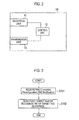
Fig. 2 is a functional block diagram of a mobile station according to the first embodiment of the present invention. -
Fig. 3 is a flowchart for describing an operation of the mobile station according to the first embodiment of the present invention. -
Fig. 4 is a functional block diagram of a radio base station according to a second embodiment of the present invention. -
Fig. 5 is a flowchart for describing an operation of the radio base station according to the second embodiment of the present invention. -
Fig. 6 is a diagram for describing a conventional mobile communication system. - A mobile communication system according to a first embodiment of the present invention will be described with reference to
Figs. 1 to 3 . - The mobile communication system according to the present embodiment supports the LTE-Advanced scheme and is configured to be capable of performing a CA using Pcell and Scell.
- Specifically, the mobile communication system according to the present embodiment is configured to be capable of performing "inter-band CA".
- As illustrated in
Fig. 1 , the mobile communication system according to the present embodiment includes a radio base station eNB that manages a PCC andScells # 1 to #3 of a mobile station UE. - Incidentally, a Pcell is a serving cell in the PCC, the
Scell # 1 is a serving cell in anSCC # 1, theScell # 2 is a serving cell in anSCC # 2, and theScell # 3 is a serving cell in anSCC # 3. - Incidentally, in the present embodiment, as illustrated in
Fig. 6(b) , a case where a TAG to which theScell # 2 belongs is modified fromTAG # 2 toTAG # 1 in a state in which the mobile station UE performs a CA using the Pcell and theScells # 1 to #4 will be described as an example. - As illustrated in
Fig. 2 , the mobile station UE according to the present embodiment includes areception unit 11, acontrol unit 12, and atransmission unit 13. - The
reception unit 11 is configured to receive various signals from the radio base station eNB. Thetransmission unit 13 is configured to transmit various signals to the radio base station eNB. Thecontrol unit 12 is configured to perform various controls. - For example, the
reception unit 11 is configured to receive an "RRC Connection Reconfiguration (TAG modification)" from the radio base station eNB. The "RRC Connection Reconfiguration (TAG modification)" instructs the TAG, to which theScell # 2 belongs, to be modified fromTAG # 2 toTAG # 1. - Incidentally, when it is instructed to modify the TAG, to which the
Scell # 2 belongs, fromTAG # 2 toTAG # 1, for example, when the "RRC Connection Reconfiguration (TAG modification)" is received, thecontrol unit 12 may modify the TAG, to which theScell # 2 belongs, fromTAG # 2 toTAG # 1 and simultaneously deactivate theScell # 2. - According to such a configuration, while the procedure of modifying the TAG, to which the
Scell # 2 belongs, fromTAG # 2 toTAG # 1 is performed, the mobile station UE cannot transmit the uplink signal in theScell # 2. Therefore, it is possible to avoid the occurrence of interference with respect to another uplink signal. - Alternatively, when it is instructed to modify the TAG, to which the
Scell # 2 belongs, fromTAG # 2 toTAG # 1, for example, when the above-described "RRC Connection Reconfiguration (TAG modification) " is received, thecontrol unit 12 may modify the TAG, to which theScell # 2 belongs, fromTAG # 2 toTAG # 1 and simultaneously stop the TAT in at least one ofTAG # 1 andTAG # 2. - Herein, the
control unit 12 may be configured to recognize such a TAT as having expired and perform subsequent processing, instead of actually stopping the above-described TAT. - The case where the
control unit 12 performs a special control such as handover or deactivation of the Scell has been described above. However, when instructing to modify the TAG, to which theScell # 2 belongs, fromTAG # 2 toTAG # 1, thecontrol unit 12 may be configured to simply stop uplink transmission in theScell # 2. - However, in such a case, the mobile station UE may be configured to designate a trigger to resume the
Scell # 2 after the TAG, to which theScell # 2 belongs, is modified fromTAG # 2 toTAG # 1. - Such a trigger may be a control signal from the radio base station eNB, or may be a delivery confirmation signal from the radio base station eNB with respect to a notification signal of TAG modification procedure completion transmitted from the mobile station UE.
- Furthermore, the control signal or the delivery confirmation signal may be transmitted in a physical layer, or may be transmitted in any of an upper RLC layer, a PDCP layer, and an RRC layer.
- According to such a configuration, while the procedure of modifying the TAG, to which the
Scell # 2 belongs, fromTAG # 2 toTAG # 1 is performed, the mobile station UE determines that the TAT of the TAG (TAG # 1 or TAG #2) to which theScell # 2 belongs is stopped, that is, determines that the uplink synchronization in theScell # 2 is deviated, and thus, the mobile station UE cannot transmit the uplink signal in theScell # 2. This makes it possible to avoid the occurrence of interference with respect to another uplink signal. - Also, when the
control unit 12 completes the procedure of modifying the TAG, to which theScell # 2 belongs, fromTAG # 2 toTAG # 1 as described above, thetransmission unit 13 is configured to transmit an "RRC Connection Reconfiguration Complete" to the radio base station eNB. - Hereinafter, the operation of the mobile station UE according to the present embodiment will be described with reference to
Fig. 3 . - As illustrated in
Fig. 3 , in step S101, the mobile station UE receives an "RRC Connection Reconfiguration (TAG modification)" from the radio base station eNB. - In step S102, the mobile station UE modifies the mapping of the TAG and the Scell, which is instructed by the "RRC Connection Reconfiguration (TAG modification)", and deactivates the Scell to be modified.
- Alternatively, in step S102, the mobile station UE modifies the mapping of the TAG and the Scell, which is instructed by the "RRC Connection Reconfiguration (TAG modification)", and recognizes that the TAT of at least one of the TAG to which the Scell to be modified belongs before modification and the TAG to which the Scell to be modified will belong after modification has expired.
- According to the invention of the present embodiment, while the procedure of modifying the TAG, to which the
Scell # 2 belongs, fromTAG # 2 toTAG # 1 is performed, it is possible to avoid a situation where the radio base station eNB cannot receive the uplink signal from the mobile station UE in theScell # 2, and such an uplink signal becomes interference with respect to another uplink signal, which is occurred as a result of using different TA values, TAT, and "DL Timing Reference Cell" between the mobile station UE and the radio base station eNB upon transmission and reception of the uplink signal in theScell # 2. - Hereinafter, a mobile communication system according to a second embodiment of the present invention will be described with reference to
Figs. 4 and 5 , focusing on differences from the above-described mobile communication system according to the first embodiment. - As illustrated in
Fig. 4 , in the mobile communication system according to the present embodiment, a radio base station eNB includes acontrol unit 21, atransmission unit 22, and areception unit 23. - The
transmission unit 22 is configured to transmit various signals to the mobile station UE. Thereception unit 23 is configured to receive various signals from the mobile station UE. Thecontrol unit 21 is configured to perform various controls. - When determining to modify the TAG, to which the
Scell # 2 of the mobile station UE belongs, fromTAG # 2 toTAG # 1, thecontrol unit 21 may be configured to deactivate theScell # 2 before instructing the mobile station UE to modify the TAG, to which theScell # 2 belongs, fromTAG # 2 toTAG # 1. - According to such a configuration, while the procedure of modifying the TAG, to which the
Scell # 2 belongs, fromTAG # 2 toTAG # 1 is performed, the mobile station UE cannot transmit the uplink signal in theScell # 2. Therefore, it is possible to avoid the occurrence of interference with respect to another uplink signal. - Alternatively, when determining to modify the TAG, to which the
Scell # 2 of the mobile station UE belongs, fromTAG # 2 toTAG # 1, that is, when instructing the mobile station UE to modify the TAG, to which theScell # 2 belongs, fromTAG # 2 toTAG # 1, thecontrol unit 21 may be configured to instruct the mobile station UE to perform handover. - When the handover is performed, all Scells are deactivated. Thus, while the procedure of modifying the TAG, to which the
Scell # 2 belongs, fromTAG # 2 toTAG # 1, the mobile station UE cannot transmit the uplink signal in theScell # 2. This makes it possible to avoid the occurrence of interference with respect to another uplink signal. - Alternatively, when determining to modify the TAG, to which the
Scell # 2 of the mobile station UE belongs, fromTAG# 2 toTAG # 1, that is, when instructing the mobile station UE to modify the TAG, to which theScell # 2 belongs, fromTAG # 2 toTAG # 1, thecontrol unit 21 may be configured to stop scheduling in theScell # 2. - According to such a configuration, while the procedure of modifying the TAG, to which the
Scell # 2 belongs, fromTAG # 2 toTAG # 1 is performed, the mobile station UE cannot transmit the uplink signal in theScell # 2. Therefore, it is possible to avoid the occurrence of interference with respect to another uplink signal. - Incidentally, when determining to modify the TAG, to which the
Scell # 2 of the mobile station UE belongs, fromTAG# 2 toTAG # 1, thecontrol unit 21 may be configured to deconfigure a Sounding Reference Symbol (SRS) transmitted by the mobile station UE before instructing the mobile station UE to modify the TAG, to which theScell # 2 belongs, fromTAG # 2 toTAG # 1. - When the
control unit 21 determines to modify the TAG, to which theScell # 2 of the mobile station UE belongs, fromTAG# 2 toTAG # 1, thetransmission unit 22 is configured to transmit an "RRC Connection Reconfiguration (TAG modification)" that instructs the mobile station UE to modify the TAG, to which theScell # 2 belongs, fromTAG # 2 toTAG # 1. - Also, the
reception unit 23 is configured to receive, from the mobile station UE, an "RRC Connection Reconfiguration Complete" that indicates the completion of the procedure of modifying the TAG, to which theScell # 2 belongs, fromTAG # 2 toTAG # 1. - Hereinafter, the operation of the radio base station eNB according to the present embodiment will be described with reference to
Fig. 5 . - As illustrated in
Fig. 5 , in step S201, the radio base station eNB determines to modify the TAG, to which theScell # 2 of the mobile station UE belongs, fromTAG # 2 toTAG # 1. - In step S202, the radio base station eNB deactivates the
Scell # 2 before instructing the mobile station UE to modify the TAG, to which theScell # 2 belongs, fromTAG # 2 toTAG # 1. - Incidentally, after completing the above-described modification procedure, that is, after receiving the "RRC Connection Reconfiguration Complete" from the mobile station UE, the radio base station eNB may, if necessary, activate the
Scell # 2 using control information of a MAC layer. - Alternatively, in step 5202, when instructing the mobile station UE to modify the TAG, to which the
Scell # 2 belongs, fromTAG # 2 toTAG # 1, the radio base station eNB instructs the mobile station UE to perform handover. - Alternatively, in step S202, when instructing the mobile station UE to modify the TAG, to which the
Scell # 2 belongs, fromTAG# 2 toTAG # 1, the radio base station eNB stops scheduling in theScell # 2. - According to the mobile communication system of the present embodiment, while the procedure of modifying the TAG, to which the
Scell # 2 belongs, fromTAG # 2 toTAG # 1 is performed, it is possible to avoid a situation where the radio base station eNB cannot receive the uplink signal from the mobile station UE in theScell # 2, and such an uplink signal becomes interference with respect to another uplink signal, which is occurred as a result of using different TA values, TAT, and "DL Timing Reference Cell" between the mobile station UE and the radio base station eNB upon transmission and reception of the uplink signal in theScell # 2. - The features of the present embodiments described above may also be expressed as follows.
- According to a first feature of the present embodiment, there is provided a mobile station UE, which is configured to be capable of performing a CA (carrier aggregation) using a Pcell (primary cell) and a Scell (secondary cell), the mobile station UE including: a
control unit 12 configured to deactivateScell # 2 when it is instructed to modify a TAG (timing advance group), to which Scell #2 (target secondary cell) belongs, from TAG #2 (first timing advance group) to TAG #1 (second timing advance group). - According to a second feature of the present embodiment, there is provided a mobile station UE, which is configured to be capable of performing a CA using Pcell and Scell, the mobile station UE including: a
transmission unit 13 configured such that an uplink signal is not transmitted in Scell belonging to a TAG in which a TAT (time alignment timer) is stopped; and acontrol unit 12 configured to stop a TAT of at least one ofTAG # 1 andTAG # 2 when it is instructed to modify a TAG, to whichScell # 2 belongs, from theTAG # 2 to theTAG # 1. - According to a third feature of the present embodiment, there is provided a radio base station eNB, which is used in a mobile communication system configured such that a mobile station UE is capable of performing a CA using Pcell and Scell, the radio base station eNB including: a
control unit 21 configured to deactivateScell # 2 before instructing the mobile station UE to modify a TAG, to which theScell # 2 belongs, fromTAG # 2 toTAG # 1. - According to a fourth feature of the present embodiment, there is provided a radio base station eNB, which is used in a mobile communication system configured such that a mobile station UE is capable of performing a CA using Pcell and Scell, the radio base station eNB including: a
control unit 21 configured to instruct the mobile station UE to perform handover when instructing the mobile station UE to modify a TAG, to which theScell # 2 belongs, fromTAG # 2 toTAG # 1. - According to a fifth feature of the present embodiment, there is provided a radio base station eNB, which is used in a mobile communication system configured such that a mobile station UE is capable of performing a CA using Pcell and Scell, the radio base station eNB including: a
control unit 21 configured to stop scheduling inScell # 2 when instructing the mobile station UE to modify a TAG, to which theScell # 2 belongs, fromTAG # 2 toTAG # 1. - In the fifth feature of the present embodiment, the
control unit 21 may be configured to deconfigure SRS transmitted by the mobile station UE prior to the instruction described above. - According to a sixth feature of the present embodiment, there is provided a mobile station UE, which is configured to be capable of performing a CA using Pcell and Scell, the mobile station UE including: a
control unit 12 configured to stop uplink transmission inScell # 2 when it is instructed to modify a TAG, to which theScell # 2 belongs, fromTAG # 2 toTAG # 1. - Incidentally, the operation of the mobile station UE and the radio base station eNB described above may be implemented by hardware, may be implemented by a software module that is executed by a processor, or may be implemented by a combination of the hardware and the software module.
- The software module may be provided in any type of storage medium, such as a Random Access Memory (RAM), a flash memory, a Read Only Memory (ROM), an Erasable Programmable ROM (EPROM), an Electronically Erasable and Programmable ROM (EEPROM), a register, a hard disk, a removable disk, or a CD-ROM.
- Such a storage medium is connected to the processor so that the processor can read and write information from and to the storage medium. Also, such a storage medium may be integrated into the processor. Furthermore, the storage medium and the processor may be provided inside an ASIC. The ASIC may be provided in the mobile station UE or the radio base station eNB. Moreover, the storage medium and the processor may be provided in the mobile station UE and the radio base station eNB as discrete components.
- While the present invention has been described in detail with reference to the above-described embodiments, it is apparent to those skilled in the art that the present invention is not limited to the embodiments described in this specification. Furthermore, various changes and modifications can be made without departing from the spirit and scope of the invention as defined by the appended claims. Therefore, the descriptions of the present specification are intended for illustrative purposes and have no restrictive meaning for the present invention.
- Incidentally, all contents in Japanese Patent Application No.
2012-108515 (filed on May 10, 2012 - As described above, the present invention can provide a mobile station and a radio base station which are capable of solving the above-described problems in a procedure of modifying the mapping of TAG and Scell.
-
- UE
- Mobile station
- eNB
- Radio base station
- 11, 23
- Reception unit
- 12, 21
- Control unit
- 13, 22
- Transmission unit
Claims (7)
- A mobile station, which is configured to be capable of performing carrier aggregation using a primary cell and a secondary cell, the mobile station comprising:a control unit configured to deactivate a target secondary cell when it is instructed to modify a timing advance group, to which the target secondary cell belongs, from a first timing advance group to a second timing advance group.
- A mobile station, which is configured to be capable of performing carrier aggregation using a primary cell and a secondary cell, the mobile station comprising:a transmission unit configured such that an uplink signal is not transmitted in a secondary cell belonging to a timing advance group in which a time alignment timer is stopped; anda control unit configured to stop a time alignment timer of at least one of a first timing advance group and a second timing advance group when it is instructed to modify a timing advance group, to which a target secondary cell belongs, from the first timing advance group to the second timing advance group.
- A radio base station, which is used in a mobile communication system configured such that a mobile station is capable of performing carrier aggregation using a primary cell and a secondary cell, the radio base station comprising:a control unit configured to deactivate a target secondary cell before instructing the mobile station to modify a timing advance group, to which the target secondary cell belongs, from a first timing advance group to a second timing advance group.
- A radio base station, which is used in a mobile communication system configured such that a mobile station is capable of performing carrier aggregation using a primary cell and a secondary cell, the radio base station comprising:a control unit configured to instruct the mobile station to perform handover when instructing the mobile station to modify a timing advance group, to which a target secondary cell belongs, from a first timing advance group to a second timing advance group.
- A radio base station, which is used in a mobile communication system configured such that a mobile station is capable of performing carrier aggregation using a primary cell and a secondary cell, the radio base station comprising:a control unit configured to stop scheduling in a target secondary cell when instructing the mobile station to modify a timing advance group, to which the target secondary cell belongs, from a first timing advance group to a second timing advance group.
- The radio base station according to claim 5, wherein the control unit is configured to deconfigure SRS transmitted by the mobile station prior to the instruction.
- A mobile station, which is configured to be capable of performing carrier aggregation using a primary cell and a secondary cell, the mobile station comprising:a control unit configured to stop uplink transmission in a target secondary cell when it is instructed to modify a timing advance group, to which the target secondary cell belongs, from a first timing advance group to a second timing advance group.
Applications Claiming Priority (2)
| Application Number | Priority Date | Filing Date | Title |
|---|---|---|---|
| JP2012108515A JP5426718B2 (en) | 2012-05-10 | 2012-05-10 | Mobile station and radio base station |
| PCT/JP2013/061515 WO2013168533A1 (en) | 2012-05-10 | 2013-04-18 | Mobile station and wireless base station |
Publications (2)
| Publication Number | Publication Date |
|---|---|
| EP2793522A1 true EP2793522A1 (en) | 2014-10-22 |
| EP2793522A4 EP2793522A4 (en) | 2015-11-04 |
Family
ID=49550584
Family Applications (1)
| Application Number | Title | Priority Date | Filing Date |
|---|---|---|---|
| EP13788111.6A Withdrawn EP2793522A4 (en) | 2012-05-10 | 2013-04-18 | MOBILE STATION AND WIRELESS BASE STATION |
Country Status (8)
| Country | Link |
|---|---|
| US (1) | US20150117404A1 (en) |
| EP (1) | EP2793522A4 (en) |
| JP (1) | JP5426718B2 (en) |
| KR (1) | KR101541041B1 (en) |
| CN (1) | CN104272832A (en) |
| CA (1) | CA2861773A1 (en) |
| RU (1) | RU2014147375A (en) |
| WO (1) | WO2013168533A1 (en) |
Cited By (1)
| Publication number | Priority date | Publication date | Assignee | Title |
|---|---|---|---|---|
| EP2804432B1 (en) * | 2012-01-10 | 2020-12-16 | Sharp Kabushiki Kaisha | Wireless communication system, mobile station device, base station device, wireless communication method, and integrated circuit |
Families Citing this family (6)
| Publication number | Priority date | Publication date | Assignee | Title |
|---|---|---|---|---|
| US10462758B2 (en) | 2014-08-05 | 2019-10-29 | Qualcomm Incorporated | Timing alignment procedures for dual PUCCH |
| US11006470B1 (en) * | 2018-08-27 | 2021-05-11 | Sprint Spectrum L.P. | Controlling use of carrier as secondary carrier for carrier-aggregation service |
| WO2020144786A1 (en) * | 2019-01-09 | 2020-07-16 | 株式会社Nttドコモ | Terminal and communication method |
| JP2025528702A (en) * | 2022-07-27 | 2025-09-02 | 北京小米移動軟件有限公司 | Uplink timing maintenance, terminal operation determination method and device, and storage medium |
| CN120731630A (en) * | 2023-02-24 | 2025-09-30 | 上海诺基亚贝尔股份有限公司 | Method, device and computer program |
| WO2024225242A1 (en) * | 2023-04-24 | 2024-10-31 | 株式会社Nttドコモ | Terminal, wireless communication method, and base station |
Family Cites Families (11)
| Publication number | Priority date | Publication date | Assignee | Title |
|---|---|---|---|---|
| ES2896335T3 (en) * | 2008-11-10 | 2022-02-24 | Blackberry Ltd | Method and apparatus of transition to an efficient battery state or configuration indicating end of data transmission |
| CN105306187A (en) * | 2009-11-19 | 2016-02-03 | 交互数字专利控股公司 | Wireless transmit/receive unit (WTRU) and method for processing carrier aggregation implementing the same |
| JP2012070134A (en) * | 2010-09-22 | 2012-04-05 | Sharp Corp | Communication system, mobile station apparatus, base station apparatus, random access transmission method, and integrated circuit |
| WO2012042736A1 (en) * | 2010-09-30 | 2012-04-05 | パナソニック株式会社 | Wireless communication apparatus, wireless communication system, and wireless communication terminal |
| US9402255B2 (en) * | 2010-09-30 | 2016-07-26 | Panasonic Intellectual Property Corporation Of America | Timing advance configuration for multiple uplink component carriers |
| KR20120136867A (en) * | 2011-06-10 | 2012-12-20 | 주식회사 팬택 | Apparatus and method for performing uplink synchronization in multiple component carrier system |
| US9191166B2 (en) * | 2011-11-04 | 2015-11-17 | Samsung Electronics Co., Ltd. | Apparatus and method for defining timing reference for secondary cells in a secondary timing advance group |
| JP5927901B2 (en) * | 2011-12-26 | 2016-06-01 | シャープ株式会社 | Mobile station apparatus, base station apparatus, communication system, uplink transmission control method, and integrated circuit |
| CN102573099B (en) * | 2012-01-13 | 2015-12-09 | 电信科学技术研究院 | A kind of method and device upgrading the descending timing reference carrier wave of sTAG |
| US9237537B2 (en) * | 2012-01-25 | 2016-01-12 | Ofinno Technologies, Llc | Random access process in a multicarrier base station and wireless device |
| WO2013151651A1 (en) * | 2012-04-01 | 2013-10-10 | Dinan Esmael Hejazi | Cell group configuration in a wireless device and base station with timing advance groups |
-
2012
- 2012-05-10 JP JP2012108515A patent/JP5426718B2/en not_active Expired - Fee Related
-
2013
- 2013-04-18 WO PCT/JP2013/061515 patent/WO2013168533A1/en not_active Ceased
- 2013-04-18 CA CA 2861773 patent/CA2861773A1/en not_active Abandoned
- 2013-04-18 US US14/373,649 patent/US20150117404A1/en not_active Abandoned
- 2013-04-18 CN CN201380023545.8A patent/CN104272832A/en active Pending
- 2013-04-18 EP EP13788111.6A patent/EP2793522A4/en not_active Withdrawn
- 2013-04-18 KR KR1020147018121A patent/KR101541041B1/en not_active Expired - Fee Related
- 2013-04-18 RU RU2014147375A patent/RU2014147375A/en not_active Application Discontinuation
Cited By (1)
| Publication number | Priority date | Publication date | Assignee | Title |
|---|---|---|---|---|
| EP2804432B1 (en) * | 2012-01-10 | 2020-12-16 | Sharp Kabushiki Kaisha | Wireless communication system, mobile station device, base station device, wireless communication method, and integrated circuit |
Also Published As
| Publication number | Publication date |
|---|---|
| CN104272832A (en) | 2015-01-07 |
| CA2861773A1 (en) | 2013-11-14 |
| US20150117404A1 (en) | 2015-04-30 |
| JP5426718B2 (en) | 2014-02-26 |
| WO2013168533A1 (en) | 2013-11-14 |
| JP2013236314A (en) | 2013-11-21 |
| EP2793522A4 (en) | 2015-11-04 |
| KR101541041B1 (en) | 2015-08-03 |
| RU2014147375A (en) | 2016-07-10 |
| KR20140094031A (en) | 2014-07-29 |
Similar Documents
| Publication | Publication Date | Title |
|---|---|---|
| JP5438046B2 (en) | Mobile communication method and radio base station | |
| EP2793522A1 (en) | Mobile station and wireless base station | |
| US9673955B2 (en) | Mobile station | |
| US9521639B2 (en) | Mobile communication system | |
| US10555272B2 (en) | Mobile station for notifying timing adjustment capabilities | |
| EP2824979A1 (en) | Wireless base station | |
| US10687363B2 (en) | Mobile station | |
| US9936471B2 (en) | Mobile station for performing component carrier-to-timing advance group mapping | |
| JP2017017728A (en) | Mobile station | |
| WO2013115263A1 (en) | Radio base station and mobile stations | |
| US10880054B2 (en) | Mobile station | |
| JP2018110458A (en) | Mobile station | |
| JP2013225907A (en) | Mobile station | |
| JP2014033410A (en) | Mobile station and wireless base station | |
| JP2013243483A (en) | Radio base station |
Legal Events
| Date | Code | Title | Description |
|---|---|---|---|
| PUAI | Public reference made under article 153(3) epc to a published international application that has entered the european phase |
Free format text: ORIGINAL CODE: 0009012 |
|
| 17P | Request for examination filed |
Effective date: 20140717 |
|
| AK | Designated contracting states |
Kind code of ref document: A1 Designated state(s): AL AT BE BG CH CY CZ DE DK EE ES FI FR GB GR HR HU IE IS IT LI LT LU LV MC MK MT NL NO PL PT RO RS SE SI SK SM TR |
|
| DAX | Request for extension of the european patent (deleted) | ||
| RA4 | Supplementary search report drawn up and despatched (corrected) |
Effective date: 20151005 |
|
| RIC1 | Information provided on ipc code assigned before grant |
Ipc: H04W 72/04 20090101AFI20150929BHEP Ipc: H04L 5/00 20060101ALI20150929BHEP Ipc: H04W 56/00 20090101ALI20150929BHEP Ipc: H04W 36/00 20090101ALI20150929BHEP Ipc: H04W 36/06 20090101ALI20150929BHEP |
|
| STAA | Information on the status of an ep patent application or granted ep patent |
Free format text: STATUS: THE APPLICATION HAS BEEN WITHDRAWN |
|
| 18W | Application withdrawn |
Effective date: 20170613 |