EP2793412A1 - Bi-directional optical communication method and multi-core optical fiber - Google Patents
Bi-directional optical communication method and multi-core optical fiber Download PDFInfo
- Publication number
- EP2793412A1 EP2793412A1 EP12847656.1A EP12847656A EP2793412A1 EP 2793412 A1 EP2793412 A1 EP 2793412A1 EP 12847656 A EP12847656 A EP 12847656A EP 2793412 A1 EP2793412 A1 EP 2793412A1
- Authority
- EP
- European Patent Office
- Prior art keywords
- cores
- core
- optical fiber
- core optical
- signal light
- Prior art date
- Legal status (The legal status is an assumption and is not a legal conclusion. Google has not performed a legal analysis and makes no representation as to the accuracy of the status listed.)
- Granted
Links
Images





Classifications
-
- G—PHYSICS
- G02—OPTICS
- G02B—OPTICAL ELEMENTS, SYSTEMS OR APPARATUS
- G02B6/00—Light guides; Structural details of arrangements comprising light guides and other optical elements, e.g. couplings
- G02B6/02—Optical fibres with cladding with or without a coating
- G02B6/02042—Multicore optical fibres
-
- G—PHYSICS
- G02—OPTICS
- G02B—OPTICAL ELEMENTS, SYSTEMS OR APPARATUS
- G02B6/00—Light guides; Structural details of arrangements comprising light guides and other optical elements, e.g. couplings
- G02B6/24—Coupling light guides
- G02B6/42—Coupling light guides with opto-electronic elements
- G02B6/4201—Packages, e.g. shape, construction, internal or external details
- G02B6/4246—Bidirectionally operating package structures
-
- H—ELECTRICITY
- H04—ELECTRIC COMMUNICATION TECHNIQUE
- H04B—TRANSMISSION
- H04B10/00—Transmission systems employing electromagnetic waves other than radio-waves, e.g. infrared, visible or ultraviolet light, or employing corpuscular radiation, e.g. quantum communication
- H04B10/25—Arrangements specific to fibre transmission
- H04B10/2581—Multimode transmission
Definitions
- the present invention relates to a method of performing bi-directional optical communication by using a multi-core optical fiber as an optical transmission line, and relates to a multi-core optical fiber suitably used in the bi-directional optical communication.
- optical communication which uses a standard single core optical fiber as an optical transmission line in optical communication which uses a multi-core optical fiber as an optical transmission line, there is an advantage that a construction cost and maintenance cost per capacity are cheap since large amount of information can be transmitted/received by a smaller number of optical fibers.
- the present inventors have examined conventional multi-core optical fibers, and as a result, have discovered the following problems.
- inter-core crosstalk becomes a factor for performance degradation.
- an invention trying to cope with performance degradation due to the inter-core crosstalk by the improvement of a structure of the multi-core optical fiber, but there is not known an invention trying to cope with it from a viewpoint of an optical communication method.
- the present invention has been developed to eliminate the problems described above. It is an object of the present invention to provide a method of performing bi-directional optical communication by using a multi-core optical fiber as an optical transmission line, the method being capable of reducing a crosstalk among cores. In addition, the object is to provide a multi-core optical fiber suitably used in such bi-directional optical communication.
- a bi-directional optical communication method performs bi-directional optical communication by using, as an optical transmission line, a multi-core optical fiber having four or more of cores in a common cladding.
- a bi-directional optical communication method according to a first aspect, one-way optical communication is performed in each of the cores of the multi-core optical fiber.
- signal light is transmitted in a first direction through an arbitrary core among the cores of the multi-core optical fiber, whereas the signal light is transmitted in a second direction opposite to the first direction, through all the nearest-neighbor cores with respect to the arbitrary core. Note that, dummy cores which do not contribute to optical communication are excluded from the above cores.
- the multi-core optical fiber has an even number of cores in the cladding.
- the cores may be arranged at lattice points of a square lattice, in a cross-section perpendicular to a central axis of the multi-core optical fiber.
- the cores may be arranged at regular intervals on a circumference of a common circle, in the cross-section perpendicular to the central axis of the multi-core optical fiber.
- a multi-core optical fiber according to a sixth aspect has plural cores in a common cladding.
- the multi-core optical fiber according to the sixth aspect while having a shape extending along a central axis, has a first end face and a second end face opposing the first end face.
- each of the cores has an input end into which the signal light is inputted, and an output end from which the signal light is outputted.
- the input end of each of the cores is arranged on the first end face or the second end faces
- the output end of each of the cores is arranged on the first end face or the second end faces so that the signal light is transmitted in a first direction through the arbitrary core among the cores, whereas the signal light is transmitted in a second direction opposite to the first direction, through all the nearest-neighbor cores with respect to the arbitrary core.
- the multi-core optical fiber according to a seventh aspect applicable to the sixth aspect is also a multi-core optical fiber having plural cores in a common cladding.
- the cores are arranged at other lattice points excluding one specific lattice point among lattice points of a square lattice, the square lattice having an odd number of lattice points.
- a marker for specifying arrangement of the cores is provided in the vicinity of the specific lattice point.
- the multi-core optical fiber according to a ninth aspect applicable to the sixth aspect is also a multi-core optical fiber having plural cores in a common cladding.
- each of the cores in a cross-section perpendicular to a central axis of the multi-core optical fiber, is arranged on one of circumferences of first and second circles having a common center while cores on each of the circumferences among the cores are arranged at regular intervals.
- a core arrangement interval on the circumference of the first circle is a first value
- a core arrangement interval on the circumference of the second circle is a second value
- a radius difference between the first and the second circles is a third value
- the maximum among the first to third values is not more than twice a minimum value among the first to third values.
- the bi-directional optical communication method performs bi-directional optical communication by using, as an optical transmission line, a multi-core optical fiber according to at least one of the sixth to tenth aspects.
- one-way optical communication is performed in each of plural cores of the multi-core optical fiber.
- signal light is transmitted in a first direction through an arbitrary core among the cores of the multi-core optical fiber, whereas the signal light is transmitted in a second direction opposite to the first direction, through all the nearest-neighbor cores with respect to the arbitrary core.
- a crosstalk among cores can be reduced in the case where bi-directional optical communication is performed using the multi-core optical fiber as an optical transmission line.
- 1 bi-directional optical communication system; 10A to 10F ... multi-core optical fiber; 11, 12 ... core; 13 ... cladding; 14 ... marker; 21, 22 ... optical transmission/reception device; 30 ... optical connection member.
- FIG. 1 is a view showing a schematic configuration example of a bi-directional optical communication system according to a first embodiment.
- a bi-directional optical communication system 1 conceptually shown in Fig. 1 comprises a multi-core optical fiber 10A and bi-directional optical transmission/reception devices 21, 22, and performs bi-directional optical communication between the optical transmission/reception device 21 and optical transmission/reception device 22 by using the multi-core optical fiber 10A as an optical transmission line.
- the multi-core optical fiber 10A while having a shape extending along a central axis AX, has a first end face 10a, and a second end face 10b opposing the first end face 10a.
- An input end or an output end of each of a plurality of cores 11, 12 included in the multi-core optical fiber 10A is arranged on one of the first and second end faces 10a, 10b.
- Fig. 2 is a cross-sectional view (corresponding to a plane perpendicular to the central axis AX) of the multi-core optical fiber 10A used as the optical transmission line in the bi-directional optical communication method according to the first embodiment.
- Fig. 2 and the subsequent cross-sectional views show a cross section perpendicular to a fiber axis.
- an auxiliary line for describing arrangement of cores is shown by a dotted line.
- the multi-core optical fiber 10A has four cores 11, 12 within a common cladding 13. Each refractive index of the four cores 11, 12 is higher than a refractive index of the cladding 13.
- a center position of a square of a dotted line shown within Fig. 2 is in agreement with a center position of the cladding 13, and a length of one side of the square is 50 ⁇ m, and the cores 11, 12 are arranged at four vertices of the square.
- a center position of a circle of a dotted line shown within Fig. 2 is in agreement with the center position of the cladding 13, and a radius of the circle is 35.4 ⁇ m, and the cores 11, 12 are arranged on a circumference of the circle at regular intervals.
- a diameter of each of the cores 11, 12 is 8 ⁇ m, and a relative refractive index difference between each of the cores 11, 12 and the cladding 13 is 0.4%, and a diameter of the cladding 13 is 125 ⁇ m.
- each of the two cores 11 transmits signal light in one direction from the optical transmission/reception device 21 to the optical transmission/reception device 22.
- Each of the two cores 12 transmits the signal light in one direction from the optical transmission/reception device 22 to the optical transmission/reception device 21.
- the cores 11, 12 which are located at the positions closest to each other among the four cores 11, 12 make signal light be transmitted in the direction opposite to each other. It is preferred that the cores 11, 12 located at the positions closest to each other have substantially the same structure, which is, in this case, advantageous in terms of being easily manufacturable or connection loss reduction. Note that, in Fig. 2 and subsequent cross-sectional views ( Figs.
- the core 11 which transmits the signal light from the optical transmission/reception device 21 to the optical transmission/reception device 22 in one direction is indicated with a white circular area
- the core 12 which transmits the signal light from the optical transmission/reception device 22 to the optical transmission/reception device 21 in one direction is indicated with a black circular area.
- the center interval thereof is 50 ⁇ m, but such nearest-neighbor cores 11, 12 transmit the signal light in the directions opposite to each other. Therefore, as compared with a case where the cores located at the positions closest to each other transmit the signal light in the same direction, the inter-core crosstalk is reduced.
- the center interval thereof is 70.7 ⁇ m, and is expanded more greatly than the nearest-neighbor core interval (50 ⁇ m). As a result, in the multi-core optical fiber 10A, the inter-core crosstalk is also reduced.
- the inter-core crosstalk can be further reduced, or a core interval can be further narrowed while the crosstalk is maintained low.
- Fig. 1 spaces exist between the multi-core optical fiber 10A and the optical transmission/reception device 21 and between the multi-core optical fiber 10A and the optical transmission/reception device 22, and there is described a configuration in which light propagates in the spaces.
- the multi-core optical fiber 10A and the optical transmission/reception devices 21, 22 may be coupled optically.
- the cores 11, 12 of the multi-core optical fiber 10A and light emitting elements or light receiving elements of the optical transmission/reception devices 21, 22 may have a configuration in which they make direct contact with each other, or may have a configuration in which they are coupled via optical waveguides.
- elements such as an isolator or the like each of which attenuates only light traveling toward any one of the light emitting elements, may be respectively inserted between the cores 11 of the multi-core optical fiber 10A and one of the light emitting elements and between the cores 12 of the multi-core optical fiber 10A and the other of the light emitting elements.
- the insertion of such elements for attenuation is effective in preventing the destabilization of operation of a light emitting element that is caused by crosstalk light from neighboring cores reaching the light emitting element.
- incidence/emission portions of each of the optical transmission/reception devices 21, 22 have been arranged on four vertices of a square.
- the present invention is not limited to this.
- the incidence and emission portions of the optical transmission/reception device 21 are arranged on a straight line, and the cores of the multi-core optical fiber 10A are arranged on four vertices of the square, and the case where the both arrangements are different from each other is also considered.
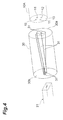
- an optical connection member 30 for arrangement conversion as shown in Fig. 4 may be inserted between the optical transmission/reception device 21 and the multi-core optical fiber 10A.
- the optical connection member 30 has four cores 31 which extend between an end face 30a and an end face 30b.
- the cores 31 are arranged on four vertices of a square in accordance with the arrangement of the cores 11, 12 of the multi-core optical fiber 10A.
- the cores 31 are arranged on a straight line in accordance with the arrangement of the incidence and emission portions of the optical transmission/reception device 21.
- optical connection member 30 may not have a fiber configuration as shown in Fig. 4 .
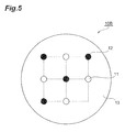
- Fig. 5 is a cross-sectional view of a multi-core optical fiber 10B used as an optical transmission line in the bi-directional optical communication method according to a second embodiment. Note that a cross-section shown in Fig. 5 corresponds to a plane perpendicular to a central axis of the multi-core optical fiber 10B in the same way as a cross-section ( Fig. 2 ) of the multi-core optical fiber 10A according to the first embodiment.
- the multi-core optical fiber 10B has eight cores 11, 12 in the common cladding 13.
- the eight cores 11, 12 are arranged at other lattice points excluding one specific lattice point located at a corner part among nine lattice points of a 3x3 square lattice of a dotted line shown in Fig. 5 .
- a center position of the 3x3 square lattice is in agreement with the center position of the cladding 13, and a length of one side of each square is 40 ⁇ m.
- a diameter of each of the cores 11, 12 is 8 ⁇ m, and a relative refractive index difference between each of the cores 11, 12 and the cladding 13 is 0.4%, and a diameter of the cladding 13 is 150 ⁇ m.
- the center interval thereof is 40 ⁇ m, but such nearest-neighbor cores11, 12 transmit the signal light in the directions opposite to each other. Therefore, as compared with a case where the cores located at the positions closest to each other transmit the signal light in the same direction, the inter-core crosstalk is reduced.
- the center interval thereof is 56.6 ⁇ m, and is expanded more greatly than the nearest-neighbor core interval (40 ⁇ m). As a result, in the multi-core optical fiber 10B, the inter-core crosstalk is also reduced.
- Fig. 6 is a cross-sectional view of a multi-core optical fiber 10C used as an optical transmission line in the bi-directional optical communication method according to a third embodiment. Note that a cross-section shown in Fig. 6 corresponds to a plane perpendicular to a central axis of the multi-core optical fiber 10C in the same way as a cross-section ( Fig. 2 ) of the multi-core optical fiber 10A according to the first embodiment.
- the multi-core optical fiber 10C has eight cores 11, 12 in a common cladding 13, and furthermore also has a marker 14.
- the multi-core optical fiber 10C has a configuration in which the marker 14 has been added to the configuration of the multi-core optical fiber 10B.
- the marker 14 is provided in the vicinity of the specific lattice point at which a core does not exist among nine lattice points of a 3x3 square lattice of a dotted line shown in Fig. 6 .
- the marker 14 is provided, for example, at a position shifted, by approximately 15 ⁇ m, from the specific lattice point, to the side of a certain core 11 which is located at the position closest to the specific lattice point.
- the marker 14 is composed of material having a refractive index lower than the refractive index of the cladding 13 so as not to function as a pseudo-core.
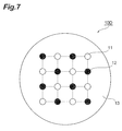
- Fig. 7 is a cross-sectional view of a multi-core optical fiber 10D used as an optical transmission line in the bi-directional optical communication method according to a fourth embodiment. Note that a cross-section shown in Fig. 7 corresponds to a plane perpendicular to a central axis of the multi-core optical fiber 10D in the same way as a cross-section ( Fig. 2 ) of the multi-core optical fiber 10A according to the first embodiment.
- the multi-core optical fiber 10D has sixteen cores 11, 12 in a common cladding 13.
- the sixteen cores 11, 12 are arranged at lattice points of a 4x4 square lattice of a dotted line shown in Fig. 7 .
- a center position of the 4x4 square lattice is in agreement with the center position of the cladding 13, and a length of one side of each square is 25 ⁇ m.
- a diameter of each of the cores 11, 12 is 6 ⁇ m, and a relative refractive index difference between each of the cores 11, 12 and the cladding 13 is 0.6%, and a diameter of the cladding 13 is 150 ⁇ m.
- the center interval thereof is 25 ⁇ m, but such nearest-neighbor cores 11, 12 transmit the signal light in the directions opposite to each other. Therefore, as compared with a case where the cores located at the positions closest to each other transmit the signal light in the same direction, the inter-core crosstalk is reduced.
- the center interval thereof is 35.3 ⁇ m, and is expanded more greatly than the nearest-neighbor core interval (25 ⁇ m). As a result, in the multi-core optical fiber 10D, the inter-core crosstalk is also reduced.
- Fig. 8 is a cross-sectional view of a multi-core optical fiber 10E used as an optical transmission line in the bi-directional optical communication method according to a fifth embodiment.
- a cross-section shown in Fig. 8 corresponds to a plane perpendicular to a central axis of the multi-core optical fiber 10E in the same way as a cross-section ( Fig. 2 ) of the multi-core optical fiber 10A according to the first embodiment.
- the multi-core optical fiber 10E has eight cores 11, 12 in the common cladding 13.
- the eight cores 11, 12 are arranged at regular intervals on a circumference of a circle of a dotted line shown in Fig. 8 .
- a center position of the circle is in agreement with the center position of the cladding 13, and a radius of the circle is 52.3 ⁇ m.
- a diameter of each of the cores 11, 12 is 8 ⁇ m, and a relative refractive index difference between each of the cores 11, 12 and the cladding 13 is 0.4%, and a diameter of the cladding 13 is 150 ⁇ m.
- the center interval thereof is 40 ⁇ m, but such nearest-neighbor cores 11, 12 transmit the signal light in the directions opposite to each other. Therefore, as compared with a case where the cores located at the positions closest to each other transmit the signal light in the same direction, the inter-core crosstalk is reduced.
- the center interval thereof is 73.9 ⁇ m, and is expanded more greatly than the closest core interval (40 ⁇ m). As a result, the inter-core crosstalk is also reduced.
- Fig. 9 is a cross-sectional view of a multi-core optical fiber 10F used as an optical transmission line in the bi-directional optical communication method according to a sixth embodiment.
- a cross-section shown in Fig. 9 corresponds to a plane perpendicular to a central axis of the multi-core optical fiber 10F in the same way as a cross-section ( Fig. 2 ) of the multi-core optical fiber 10A according to the first embodiment.
- the multi-core optical fiber 10F has sixteen cores 11, 12 in a common cladding 13. Each of the cores 11, 12 is arranged on one of circumferences of two circles expressed by a dotted line shown in Fig. 9 . Each of center positions of the inner circle and the outer circle is in agreement with the center position of the cladding 13. A radius of the inner circle is 19.1 ⁇ m, and the four cores 11, 12 are arranged at regular intervals on the circumference of the inner circle. A radius of the outer circle is 52.2 ⁇ m, and the twelve cores 11, 12 are arranged at regular intervals on the circumference of the outer circle.
- a diameter of each of the cores 11, 12 is 6 ⁇ m, and a relative refractive index difference between each of the cores 11, 12 and the cladding 13 is 0.6%, and a diameter of the cladding 13 is 150 ⁇ m.
- a core arrangement interval on the circumference of the inner circle is a first value
- a core arrangement interval on the circumference of the outer circle is a second value
- a radius difference between the inner and outer circles is a third value
- the maximum value among the first to third values is not more than twice a minimum value among the first to third values.
- a center interval thereof is 27 ⁇ m, but such nearest-neighbor cores transmit the signal light in the direction opposite to each other. Therefore, as compared with a case where the cores located in the position closest to each other transmit the signal light in the same direction, the inter-core crosstalk is reduced.
- a center interval thereof is 38.2 ⁇ m, and is expanded more greatly than the closest core interval (27 ⁇ m). As a result, the inter-core crosstalk is also reduced.
- a center interval thereof is 52.2 ⁇ m, and is expanded more greatly than the closest core interval (27 ⁇ m). Therefore, the inter-core crosstalk is reduced also by this configuration.
- a center interval between a core on the circumference of the inner circle and a core on the circumference of the outer circle which are located on the same radial line is 33.1 ⁇ m (that is, radius difference between the outer circle and the inner circle)
- the inter-core crosstalk is reduced by transmitting the signal light in the opposite directions in these cores.
- a center interval between the cores which transmit the light in the same direction on the circumference of the outer circle and the circumference of the inner circle is 36.9 ⁇ m, and is expanded more than the center interval of the cores which are located on the same radial line.
Landscapes
- Physics & Mathematics (AREA)
- General Physics & Mathematics (AREA)
- Optics & Photonics (AREA)
- Electromagnetism (AREA)
- Engineering & Computer Science (AREA)
- Computer Networks & Wireless Communication (AREA)
- Signal Processing (AREA)
- Optical Communication System (AREA)
- Optical Couplings Of Light Guides (AREA)
- Optical Fibers, Optical Fiber Cores, And Optical Fiber Bundles (AREA)
- Optical Integrated Circuits (AREA)
Abstract
Description
- The present invention relates to a method of performing bi-directional optical communication by using a multi-core optical fiber as an optical transmission line, and relates to a multi-core optical fiber suitably used in the bi-directional optical communication.
- As compared with optical communication which uses a standard single core optical fiber as an optical transmission line, in optical communication which uses a multi-core optical fiber as an optical transmission line, there is an advantage that a construction cost and maintenance cost per capacity are cheap since large amount of information can be transmitted/received by a smaller number of optical fibers.
- The present inventors have examined conventional multi-core optical fibers, and as a result, have discovered the following problems.
- That is, in the optical communication using a multi-core optical fiber as an optical transmission line, inter-core crosstalk becomes a factor for performance degradation. However, heretofore, there has been proposed an invention trying to cope with performance degradation due to the inter-core crosstalk by the improvement of a structure of the multi-core optical fiber, but there is not known an invention trying to cope with it from a viewpoint of an optical communication method.
- The present invention has been developed to eliminate the problems described above. It is an object of the present invention to provide a method of performing bi-directional optical communication by using a multi-core optical fiber as an optical transmission line, the method being capable of reducing a crosstalk among cores. In addition, the object is to provide a multi-core optical fiber suitably used in such bi-directional optical communication.
- A bi-directional optical communication method according to the present invention performs bi-directional optical communication by using, as an optical transmission line, a multi-core optical fiber having four or more of cores in a common cladding. In a bi-directional optical communication method according to a first aspect, one-way optical communication is performed in each of the cores of the multi-core optical fiber. At this time, signal light is transmitted in a first direction through an arbitrary core among the cores of the multi-core optical fiber, whereas the signal light is transmitted in a second direction opposite to the first direction, through all the nearest-neighbor cores with respect to the arbitrary core. Note that, dummy cores which do not contribute to optical communication are excluded from the above cores.
- In addition, as a second aspect applicable to the first aspect, it is preferable that the multi-core optical fiber has an even number of cores in the cladding. As a third aspect applicable to at least one of the first and second aspects, the cores may be arranged at lattice points of a square lattice, in a cross-section perpendicular to a central axis of the multi-core optical fiber. As a fourth aspect applicable to at least one of the first to third aspects, the cores may be arranged at regular intervals on a circumference of a common circle, in the cross-section perpendicular to the central axis of the multi-core optical fiber. As a fifth aspect applicable to at least one of the first to fourth aspects, it is preferable that two cores nearest-neighboring each other among the cores have substantially the same structure.
- As a multi-core optical fiber applicable to an optical transmission line of a bi-directional optical communication method according to at least one of the first to fifth aspects, a multi-core optical fiber according to a sixth aspect has plural cores in a common cladding. The multi-core optical fiber according to the sixth aspect, while having a shape extending along a central axis, has a first end face and a second end face opposing the first end face. In particular, in the sixth aspect, each of the cores has an input end into which the signal light is inputted, and an output end from which the signal light is outputted. Additionally, in the multi-core optical fiber, the input end of each of the cores is arranged on the first end face or the second end faces, and the output end of each of the cores is arranged on the first end face or the second end faces so that the signal light is transmitted in a first direction through the arbitrary core among the cores, whereas the signal light is transmitted in a second direction opposite to the first direction, through all the nearest-neighbor cores with respect to the arbitrary core.
- The multi-core optical fiber according to a seventh aspect applicable to the sixth aspect is also a multi-core optical fiber having plural cores in a common cladding. In the seventh aspect, in a cross-section perpendicular to a central axis of the multi-core optical fiber, the cores are arranged at other lattice points excluding one specific lattice point among lattice points of a square lattice, the square lattice having an odd number of lattice points. In addition, as an eighth aspect applicable to the seventh aspect, it is preferable that a marker for specifying arrangement of the cores is provided in the vicinity of the specific lattice point.
- The multi-core optical fiber according to a ninth aspect applicable to the sixth aspect is also a multi-core optical fiber having plural cores in a common cladding. In the ninth aspect, in a cross-section perpendicular to a central axis of the multi-core optical fiber, each of the cores is arranged on one of circumferences of first and second circles having a common center while cores on each of the circumferences among the cores are arranged at regular intervals. In addition, when a core arrangement interval on the circumference of the first circle is a first value, a core arrangement interval on the circumference of the second circle is a second value, and a radius difference between the first and the second circles is a third value, the maximum among the first to third values is not more than twice a minimum value among the first to third values. Note that, as a 10th aspect applicable to at least one of the sixth to ninth aspects, it is preferable that two cores nearest-neighboring each other among the cores have substantially the same structure.
- The bi-directional optical communication method according to the present invention, as a 11th aspect, performs bi-directional optical communication by using, as an optical transmission line, a multi-core optical fiber according to at least one of the sixth to tenth aspects. In the 11th aspect, one-way optical communication is performed in each of plural cores of the multi-core optical fiber. At this time, signal light is transmitted in a first direction through an arbitrary core among the cores of the multi-core optical fiber, whereas the signal light is transmitted in a second direction opposite to the first direction, through all the nearest-neighbor cores with respect to the arbitrary core.
- According to the present invention, a crosstalk among cores can be reduced in the case where bi-directional optical communication is performed using the multi-core optical fiber as an optical transmission line.
-
-
Fig. 1 is a view showing a schematic configuration example of a bi-directional optical communication system according to the first embodiment; -
Fig. 2 is a cross-sectional view of a multi-coreoptical fiber 10A used as an optical transmission line in the bi-directional optical communication method according to the first embodiment; -
Fig. 3 is a view showing another schematic configuration example of the bi-directional optical communication system according to the first embodiment; -
Fig. 4 is a view for explaining anoptical connection member 30 inserted between an optical transmission/reception device and a multi-core optical fiber; -
Fig. 5 is a cross-sectional view of a multi-coreoptical fiber 10B used as an optical transmission line in a bi-directional optical communication method according to a second embodiment; -
Fig. 6 is a cross-sectional view of a multi-coreoptical fiber 10C used as an optical transmission line in a bi-directional optical communication method according to a third embodiment; -
Fig. 7 is a cross-sectional view of a multi-coreoptical fiber 10D used as an optical transmission line in a bi-directional optical communication method according to a fourth embodiment; -
Fig. 8 is a cross-sectional view of a multi-coreoptical fiber 10E used as an optical transmission line in a bi-directional optical communication method according to a fifth embodiment; and -
Fig. 9 is a cross-sectional view of a multi-coreoptical fiber 10F used as an optical transmission line in a bi-directional optical communication method according to a sixth embodiment. - 1 ... bi-directional optical communication system; 10A to 10F ... multi-core optical fiber; 11, 12 ... core; 13 ... cladding; 14 ... marker; 21, 22 ... optical transmission/reception device; 30 ... optical connection member.
- In the following, with reference to the accompanying drawings, configurations for carrying out the present invention will be described in detail. Note that, in description of the drawings, the same symbol is given to the same component, and overlapped description is omitted.
-
Fig. 1 is a view showing a schematic configuration example of a bi-directional optical communication system according to a first embodiment. A bi-directionaloptical communication system 1 conceptually shown inFig. 1 comprises a multi-coreoptical fiber 10A and bi-directional optical transmission/reception devices reception device 21 and optical transmission/reception device 22 by using the multi-coreoptical fiber 10A as an optical transmission line. Note that the multi-coreoptical fiber 10A, while having a shape extending along a central axis AX, has afirst end face 10a, and asecond end face 10b opposing thefirst end face 10a. An input end or an output end of each of a plurality ofcores optical fiber 10A is arranged on one of the first and second end faces 10a, 10b. -
Fig. 2 is a cross-sectional view (corresponding to a plane perpendicular to the central axis AX) of the multi-coreoptical fiber 10A used as the optical transmission line in the bi-directional optical communication method according to the first embodiment. Note thatFig. 2 and the subsequent cross-sectional views show a cross section perpendicular to a fiber axis. Additionally, inFig. 2 and the subsequent cross-sectional views, for convenience of explanation thereof, an auxiliary line for describing arrangement of cores is shown by a dotted line. - The multi-core
optical fiber 10A has fourcores common cladding 13. Each refractive index of the fourcores cladding 13. A center position of a square of a dotted line shown withinFig. 2 is in agreement with a center position of thecladding 13, and a length of one side of the square is 50 µm, and thecores Fig. 2 is in agreement with the center position of thecladding 13, and a radius of the circle is 35.4 µm, and thecores cores cores cladding 13 is 0.4%, and a diameter of thecladding 13 is 125 µm. - In the multi-core
optical fiber 10A, each of the twocores 11 transmits signal light in one direction from the optical transmission/reception device 21 to the optical transmission/reception device 22. Each of the twocores 12 transmits the signal light in one direction from the optical transmission/reception device 22 to the optical transmission/reception device 21. Thecores cores cores Fig. 2 and subsequent cross-sectional views (Figs. 5 to 9 ), the core 11 which transmits the signal light from the optical transmission/reception device 21 to the optical transmission/reception device 22 in one direction is indicated with a white circular area, and the core 12 which transmits the signal light from the optical transmission/reception device 22 to the optical transmission/reception device 21 in one direction is indicated with a black circular area. - In the present embodiment, as to the
cores neighbor cores cores 11 which transmit the signal light in the same direction, or the twocores 12 which transmit the signal light in the same direction, the center interval thereof is 70.7 µm, and is expanded more greatly than the nearest-neighbor core interval (50 µm). As a result, in the multi-coreoptical fiber 10A, the inter-core crosstalk is also reduced. - Moreover, by providing a portion such as a trench, which suppresses leakage of light into adjacent cores, in the
cladding 13 near thecores - Note that, in
Fig. 1 , spaces exist between the multi-coreoptical fiber 10A and the optical transmission/reception device 21 and between the multi-coreoptical fiber 10A and the optical transmission/reception device 22, and there is described a configuration in which light propagates in the spaces. However, the multi-coreoptical fiber 10A and the optical transmission/reception devices cores optical fiber 10A and light emitting elements or light receiving elements of the optical transmission/reception devices cores 11 of the multi-coreoptical fiber 10A and one of the light emitting elements and between thecores 12 of the multi-coreoptical fiber 10A and the other of the light emitting elements. The insertion of such elements for attenuation is effective in preventing the destabilization of operation of a light emitting element that is caused by crosstalk light from neighboring cores reaching the light emitting element. - In the configuration of the optical communication system shown in
Fig. 1 , in accordance with a core arrangement of the multi-coreoptical fiber 10A, incidence/emission portions of each of the optical transmission/reception devices Fig. 3 , the incidence and emission portions of the optical transmission/reception device 21 are arranged on a straight line, and the cores of the multi-coreoptical fiber 10A are arranged on four vertices of the square, and the case where the both arrangements are different from each other is also considered. - In this case, an
optical connection member 30 for arrangement conversion as shown inFig. 4 may be inserted between the optical transmission/reception device 21 and the multi-coreoptical fiber 10A. Theoptical connection member 30 has fourcores 31 which extend between anend face 30a and anend face 30b. In theend face 30a facing the multi-coreoptical fiber 10A, thecores 31 are arranged on four vertices of a square in accordance with the arrangement of thecores optical fiber 10A. In theend face 30b facing the optical transmission/reception device 21, thecores 31 are arranged on a straight line in accordance with the arrangement of the incidence and emission portions of the optical transmission/reception device 21. As shown inFig. 4 , it is preferable that in the optical transmission/reception device 21, two light emission portions are adjacent and at the same time, two light incidence portions are adjacent. In this case, a structure of the optical transmission/reception device 21 becomes simple, and it is effective in terms of downsizing of the optical transmission/reception device 21. Theoptical connection member 30 may not have a fiber configuration as shown inFig. 4 . -
Fig. 5 is a cross-sectional view of a multi-coreoptical fiber 10B used as an optical transmission line in the bi-directional optical communication method according to a second embodiment. Note that a cross-section shown inFig. 5 corresponds to a plane perpendicular to a central axis of the multi-coreoptical fiber 10B in the same way as a cross-section (Fig. 2 ) of the multi-coreoptical fiber 10A according to the first embodiment. - The multi-core
optical fiber 10B has eightcores common cladding 13. The eightcores Fig. 5 . A center position of the 3x3 square lattice is in agreement with the center position of thecladding 13, and a length of one side of each square is 40 µm. A diameter of each of thecores cores cladding 13 is 0.4%, and a diameter of thecladding 13 is 150 µm. - In the present embodiment, as to the
cores cores 11 which transmit the signal light in the same direction, or the twocores 12 which transmit the signal light in the same direction, the center interval thereof is 56.6 µm, and is expanded more greatly than the nearest-neighbor core interval (40 µm). As a result, in the multi-coreoptical fiber 10B, the inter-core crosstalk is also reduced. -
Fig. 6 is a cross-sectional view of a multi-coreoptical fiber 10C used as an optical transmission line in the bi-directional optical communication method according to a third embodiment. Note that a cross-section shown inFig. 6 corresponds to a plane perpendicular to a central axis of the multi-coreoptical fiber 10C in the same way as a cross-section (Fig. 2 ) of the multi-coreoptical fiber 10A according to the first embodiment. - The multi-core
optical fiber 10C has eightcores common cladding 13, and furthermore also has amarker 14. The multi-coreoptical fiber 10C has a configuration in which themarker 14 has been added to the configuration of the multi-coreoptical fiber 10B. - The
marker 14 is provided in the vicinity of the specific lattice point at which a core does not exist among nine lattice points of a 3x3 square lattice of a dotted line shown inFig. 6 . Themarker 14 is provided, for example, at a position shifted, by approximately 15 µm, from the specific lattice point, to the side of acertain core 11 which is located at the position closest to the specific lattice point. By the fact that themarker 14 being provided in this manner, the arrangement of the eightcores marker 14 is composed of material having a refractive index lower than the refractive index of thecladding 13 so as not to function as a pseudo-core. -
Fig. 7 is a cross-sectional view of a multi-coreoptical fiber 10D used as an optical transmission line in the bi-directional optical communication method according to a fourth embodiment. Note that a cross-section shown inFig. 7 corresponds to a plane perpendicular to a central axis of the multi-coreoptical fiber 10D in the same way as a cross-section (Fig. 2 ) of the multi-coreoptical fiber 10A according to the first embodiment. - The multi-core
optical fiber 10D has sixteencores common cladding 13. The sixteencores Fig. 7 . A center position of the 4x4 square lattice is in agreement with the center position of thecladding 13, and a length of one side of each square is 25 µm. A diameter of each of thecores cores cladding 13 is 0.6%, and a diameter of thecladding 13 is 150 µm. - In the present embodiment, as to the
cores neighbor cores cores 11 which transmit the signal light in the same direction, or the twocores 12 which transmit the signal light in the same direction, the center interval thereof is 35.3 µm, and is expanded more greatly than the nearest-neighbor core interval (25 µm). As a result, in the multi-coreoptical fiber 10D, the inter-core crosstalk is also reduced. -
Fig. 8 is a cross-sectional view of a multi-coreoptical fiber 10E used as an optical transmission line in the bi-directional optical communication method according to a fifth embodiment. A cross-section shown inFig. 8 corresponds to a plane perpendicular to a central axis of the multi-coreoptical fiber 10E in the same way as a cross-section (Fig. 2 ) of the multi-coreoptical fiber 10A according to the first embodiment. - The multi-core
optical fiber 10E has eightcores common cladding 13. The eightcores Fig. 8 . A center position of the circle is in agreement with the center position of thecladding 13, and a radius of the circle is 52.3 µm. A diameter of each of thecores cores cladding 13 is 0.4%, and a diameter of thecladding 13 is 150 µm. - In the present embodiment, as to the
cores neighbor cores cores 11 which transmit the signal light in the same direction, or the twocores 12 which transmit the signal light in the same direction, the center interval thereof is 73.9 µm, and is expanded more greatly than the closest core interval (40 µm). As a result, the inter-core crosstalk is also reduced. -
Fig. 9 is a cross-sectional view of a multi-coreoptical fiber 10F used as an optical transmission line in the bi-directional optical communication method according to a sixth embodiment. A cross-section shown inFig. 9 corresponds to a plane perpendicular to a central axis of the multi-coreoptical fiber 10F in the same way as a cross-section (Fig. 2 ) of the multi-coreoptical fiber 10A according to the first embodiment. - The multi-core
optical fiber 10F has sixteencores common cladding 13. Each of thecores Fig. 9 . Each of center positions of the inner circle and the outer circle is in agreement with the center position of thecladding 13. A radius of the inner circle is 19.1 µm, and the fourcores cores cores cores cladding 13 is 0.6%, and a diameter of thecladding 13 is 150 µm. In addition, when a core arrangement interval on the circumference of the inner circle is a first value, a core arrangement interval on the circumference of the outer circle is a second value, and a radius difference between the inner and outer circles is a third value, the maximum value among the first to third values is not more than twice a minimum value among the first to third values. - In the present embodiment, on the circumference of each of the inner and outer circles, as to the
cores cores 11 which transmit the signal light in the same direction, or the twocores 12 which transmit the signal light in the same direction, a center interval thereof is 38.2 µm, and is expanded more greatly than the closest core interval (27 µm). As a result, the inter-core crosstalk is also reduced. Similarly, on the circumference of the outer circle, as to the twocores 11 which transmit the signal light in the same direction, or the twocores 12 which transmit the signal light in the same direction, a center interval thereof is 52.2 µm, and is expanded more greatly than the closest core interval (27 µm). Therefore, the inter-core crosstalk is reduced also by this configuration. - In addition, since a center interval between a core on the circumference of the inner circle and a core on the circumference of the outer circle which are located on the same radial line is 33.1 µm (that is, radius difference between the outer circle and the inner circle), the inter-core crosstalk is reduced by transmitting the signal light in the opposite directions in these cores. Note that a center interval between the cores which transmit the light in the same direction on the circumference of the outer circle and the circumference of the inner circle is 36.9 µm, and is expanded more than the center interval of the cores which are located on the same radial line.
Claims (11)
- A bi-directional optical communication method for performing bi-directional optical communication by using, as an optical transmission line, a multi-core optical fiber having four or more of cores in a common cladding, the method comprising the step of:performing one-way optical communication in each of the cores of the multi-core optical fiber,wherein signal light is transmitted in a first direction through an arbitrary core among the cores of the multi-core optical fiber, whereas the signal light is transmitted in a second direction opposite to the first direction, through all the nearest-neighbor cores with respect to the arbitrary core.
- The bi-directional optical communication method according to claim 1, wherein the multi-core optical fiber has an even number of cores in the cladding.
- The bi-directional optical communication method according to claim 2, wherein in a cross-section perpendicular to a central axis of the multi-core optical fiber, the cores are arranged at lattice points of a square lattice.
- The bi-directional optical communication method according to claim 2, wherein in a cross-section perpendicular to a central axis of the multi-core optical fiber, the cores are arranged at regular intervals on a circumference of a common circle.
- The bi-directional optical communication method according to any one of claims 1 to 4, wherein two cores nearest-neighboring each other among the cores have substantially the same structure.
- A multi-core optical fiber having plural cores in a common cladding, the multi-core optical fiber having:a first end face; anda second end face opposing the first end face,wherein each of the cores has an input end into which signal light is inputted, and an output end from which the signal light is outputted, andwherein the input end of each of the cores is arranged on the first end face or the second end faces, and the output end of each of the cores is arranged on the first end face or the second end faces so that the signal light is transmitted in a first direction through an arbitrary core among the cores, whereas the signal light is transmitted in a second direction opposite to the first direction, through all the nearest-neighbor cores with respect to the arbitrary core.
- A multi-core optical fiber having plural cores in a common cladding,
wherein in a cross-section perpendicular to a central axis of the multi-core optical fiber, the cores are arranged at other lattice points excluding one specific lattice point among lattice points of a square lattice, the square lattice having an odd number of lattice points. - The multi-core optical fiber according to claim 7, wherein a marker for specifying arrangement of the cores is provided in vicinity of the specific lattice point.
- A multi-core optical fiber having plural cores in a common cladding,
wherein in a cross-section perpendicular to a central axis of the multi-core optical fiber, each of the cores is arranged on one of circumferences of first and second circles having a common center while cores on each of the circumferences among the cores are arranged at regular intervals, and
wherein when a core arrangement interval on the circumference of the first circle is a first value, a core arrangement interval on the circumference of the second circle is a second value, and a radius difference between the first and second circles is a third value, a maximum value among the first to third values is not more than twice a minimum value among the first to third values. - The multi-core optical fiber according to any one of claims 6 to 9, wherein two cores nearest-neighboring each other among the cores have substantially the same structure.
- A method of performing bi-directional optical communication by using, as an optical transmission line, a multi-core optical fiber according to any one of claims 6 to 10, the method comprising the step of:performing one-way optical communication in each of the cores of the multi-core optical fiber, andwherein signal light is transmitted in a first direction through an arbitrary core among the cores of the multi-core optical fiber, whereas the signal light is transmitted in a second direction opposite to the first direction, through all the nearest-neighbor cores with respect to the arbitrary core.
Applications Claiming Priority (2)
| Application Number | Priority Date | Filing Date | Title |
|---|---|---|---|
| JP2011247508A JP5842556B2 (en) | 2011-11-11 | 2011-11-11 | Bi-directional optical communication method and multi-core optical fiber |
| PCT/JP2012/078364 WO2013069541A1 (en) | 2011-11-11 | 2012-11-01 | Bi-directional optical communication method and multi-core optical fiber |
Publications (3)
| Publication Number | Publication Date |
|---|---|
| EP2793412A1 true EP2793412A1 (en) | 2014-10-22 |
| EP2793412A4 EP2793412A4 (en) | 2015-12-02 |
| EP2793412B1 EP2793412B1 (en) | 2022-07-20 |
Family
ID=48289918
Family Applications (1)
| Application Number | Title | Priority Date | Filing Date |
|---|---|---|---|
| EP12847656.1A Active EP2793412B1 (en) | 2011-11-11 | 2012-11-01 | Bi-directional optical communication method and multi-core optical fiber |
Country Status (5)
| Country | Link |
|---|---|
| US (1) | US9244217B2 (en) |
| EP (1) | EP2793412B1 (en) |
| JP (1) | JP5842556B2 (en) |
| DK (1) | DK2793412T3 (en) |
| WO (1) | WO2013069541A1 (en) |
Families Citing this family (19)
| Publication number | Priority date | Publication date | Assignee | Title |
|---|---|---|---|---|
| JPWO2013157245A1 (en) * | 2012-04-20 | 2015-12-21 | 日本電気株式会社 | Multiplex optical transmission line, optical transmission system, and optical transmission method |
| JP2014197094A (en) * | 2013-03-29 | 2014-10-16 | 住友電気工業株式会社 | Multicore optical fiber |
| CN103438927B (en) * | 2013-06-26 | 2015-12-23 | 江苏金迪电子科技有限公司 | A kind of distribution type sensing method of multi-core fiber |
| US9696513B2 (en) * | 2013-11-22 | 2017-07-04 | Corning Optical Communications LLC | Multicore optical fibers and methods of manufacturing the same |
| JP6287179B2 (en) * | 2013-12-25 | 2018-03-07 | 住友電気工業株式会社 | Multi-core optical fiber and method for manufacturing multi-core optical fiber connector |
| JP2016015608A (en) * | 2014-07-02 | 2016-01-28 | 日本電気株式会社 | Transmission system, and transmission method |
| JP2016126235A (en) * | 2015-01-07 | 2016-07-11 | ソニー株式会社 | Optical connector |
| JP6063007B2 (en) * | 2015-07-03 | 2017-01-18 | 日本電信電話株式会社 | Optical transmission system and optical transmission method |
| JP6118372B2 (en) * | 2015-07-08 | 2017-04-19 | 日本電信電話株式会社 | Multi-core optical fiber and optical fiber cable |
| US10001597B2 (en) | 2015-09-22 | 2018-06-19 | Corning Incorporated | Multicore optical fibers and interconnection methods for the same |
| WO2017090600A1 (en) * | 2015-11-26 | 2017-06-01 | 日本電信電話株式会社 | Communication system and connector |
| US10690843B2 (en) | 2016-03-17 | 2020-06-23 | Fujikura Ltd. | Multicore fiber |
| JP7207293B2 (en) * | 2017-03-17 | 2023-01-18 | 住友電気工業株式会社 | optical connector |
| WO2022034662A1 (en) * | 2020-08-12 | 2022-02-17 | 日本電信電話株式会社 | Multicore optical fiber and design method |
| JP7518425B2 (en) | 2020-09-30 | 2024-07-18 | 日本電信電話株式会社 | Method for installing optical communication device and optical communication system |
| JP7528703B2 (en) | 2020-10-09 | 2024-08-06 | 住友電気工業株式会社 | Multi-core optical fiber and multi-core optical fiber cable |
| US12360309B2 (en) | 2020-10-09 | 2025-07-15 | Sumitomo Electric Industries, Ltd. | Multi-core optical fiber and multi-core optical fiber cable |
| CN116324547A (en) | 2021-02-19 | 2023-06-23 | 株式会社藤仓 | Optical input and output device |
| CN113589422A (en) * | 2021-06-23 | 2021-11-02 | 长飞光纤光缆股份有限公司 | Easily-identified multi-core optical fiber |
Family Cites Families (25)
| Publication number | Priority date | Publication date | Assignee | Title |
|---|---|---|---|---|
| US4070091A (en) * | 1976-04-16 | 1978-01-24 | Northern Telecom Limited | Optical fibre with enhanced security |
| JPS593026A (en) * | 1982-06-23 | 1984-01-09 | Sumitomo Electric Ind Ltd | Manufacture of optical fiber having noncircular cross section |
| JPS60263905A (en) * | 1984-06-13 | 1985-12-27 | Sumitomo Electric Ind Ltd | Micro displacement meter using multi-core fiber with periodic structure |
| US4730886A (en) * | 1985-08-06 | 1988-03-15 | Hicks John W | Fiber laser sensor |
| JP3221043B2 (en) * | 1992-04-16 | 2001-10-22 | 日立電線株式会社 | Rare earth element-doped multi-core fiber for single mode transmission and optical fiber amplifier using the same |
| FR2701571B1 (en) * | 1993-02-15 | 1995-03-17 | Georges Le Noane | Multicore optical guides of great precision and small dimensions and method of manufacturing these guides. |
| JPH0894864A (en) * | 1994-04-08 | 1996-04-12 | Olympus Optical Co Ltd | Image fiber and its production |
| US5566196A (en) * | 1994-10-27 | 1996-10-15 | Sdl, Inc. | Multiple core fiber laser and optical amplifier |
| JP2001521645A (en) * | 1997-04-21 | 2001-11-06 | ユニバーシティ・オブ・サザンプトン | Optical coupler and multiplexer |
| AUPP218198A0 (en) * | 1998-03-04 | 1998-03-26 | University Of Sydney, The | Ultra-broadband low-noise gain-flattened rare-earth-doped fibre amplifier |
| JP2000292627A (en) * | 1999-04-09 | 2000-10-20 | Mitsubishi Rayon Co Ltd | Optical transmission system |
| JP2001033636A (en) * | 1999-07-15 | 2001-02-09 | Sharp Corp | Optical fiber, optical fiber cable, and optical transceiver module |
| US6996316B2 (en) * | 1999-09-20 | 2006-02-07 | Cidra Corporation | Large diameter D-shaped optical waveguide and coupler |
| JP2001242348A (en) * | 1999-12-24 | 2001-09-07 | Asahi Kasei Corp | Optical communication method and optical communication link |
| US6757467B1 (en) * | 2000-07-25 | 2004-06-29 | Optical Air Data Systems, Lp | Optical fiber system |
| US7306344B2 (en) * | 2003-06-10 | 2007-12-11 | Abu-Ageel Nayef M | Light guide array, fabrication methods and optical system employing same |
| EP1909366A4 (en) * | 2005-07-13 | 2009-07-08 | Furukawa Electric Co Ltd | LIGHT IRRADIATION DEVICE AND WELDING METHOD |
| KR101448574B1 (en) | 2008-05-07 | 2014-10-08 | 휴렛-팩커드 디벨롭먼트 컴퍼니, 엘.피. | Optical engine for point-to-point communications |
| CN101782669B (en) * | 2009-01-20 | 2014-07-09 | 住友电气工业株式会社 | Optical communication system and arrangement converter |
| JP2010181795A (en) * | 2009-02-09 | 2010-08-19 | Sumitomo Electric Ind Ltd | Optical fiber |
| JP5281161B2 (en) * | 2009-07-08 | 2013-09-04 | 株式会社フジクラ | Optical fiber communication system |
| JP5267481B2 (en) * | 2010-02-18 | 2013-08-21 | 住友電気工業株式会社 | Multi-core optical fiber |
| JP2011209702A (en) * | 2010-03-10 | 2011-10-20 | Sumitomo Electric Ind Ltd | Multi-core optical fiber |
| JP2012203036A (en) * | 2011-03-23 | 2012-10-22 | Mitsubishi Cable Ind Ltd | Optical transmission line |
| JP2012215696A (en) * | 2011-03-31 | 2012-11-08 | Hitachi Cable Ltd | Multi-core fiber, multi-core distribution management fiber, and optical fiber communication system including multi-core distribution management fiber |
-
2011
- 2011-11-11 JP JP2011247508A patent/JP5842556B2/en active Active
-
2012
- 2012-11-01 DK DK12847656.1T patent/DK2793412T3/en active
- 2012-11-01 EP EP12847656.1A patent/EP2793412B1/en active Active
- 2012-11-01 WO PCT/JP2012/078364 patent/WO2013069541A1/en not_active Ceased
- 2012-11-08 US US13/671,928 patent/US9244217B2/en active Active
Also Published As
| Publication number | Publication date |
|---|---|
| JP5842556B2 (en) | 2016-01-13 |
| WO2013069541A1 (en) | 2013-05-16 |
| US20130129292A1 (en) | 2013-05-23 |
| CN103931120A (en) | 2014-07-16 |
| DK2793412T3 (en) | 2022-08-15 |
| EP2793412A4 (en) | 2015-12-02 |
| EP2793412B1 (en) | 2022-07-20 |
| US9244217B2 (en) | 2016-01-26 |
| JP2013106135A (en) | 2013-05-30 |
Similar Documents
| Publication | Publication Date | Title |
|---|---|---|
| US9244217B2 (en) | Bi-directional optical communication method and multi-core optical fiber | |
| US8433166B2 (en) | Multi-core optical fibre | |
| JP5347989B2 (en) | Multi-core optical fiber | |
| JP5855351B2 (en) | Multi-core fiber | |
| JP6722271B2 (en) | Multi-core fiber | |
| US20150078744A1 (en) | Multiplexed optical transmission line, optical transmission system, and optical transmission method | |
| US9529144B2 (en) | Multicore fiber | |
| EP3474050A1 (en) | Method for axial alignment of coupled multicore optical fiber | |
| JP7660655B2 (en) | Optical input/output device | |
| US11422301B2 (en) | Optical fiber cable | |
| JP2014010266A (en) | Multi-core fiber | |
| JP2014197094A (en) | Multicore optical fiber | |
| JP5811056B2 (en) | Optical component, optical fiber amplifier and optical fiber ring resonator | |
| EP4064468B1 (en) | Optical coupler and optical amplifier | |
| JP2018128562A (en) | Optical transmission device and bidirectional optical transmission device | |
| WO2017150481A1 (en) | Optical fiber transmission system | |
| JP2014052410A (en) | Multi-core optical fiber | |
| JP6192442B2 (en) | Coupled multi-core fiber | |
| JP2014048645A (en) | Multicore optical fiber, multicore optical fiber alignment method, and optical communication system | |
| JP6096268B2 (en) | Multi-core fiber | |
| CN103931120B (en) | Bi-directional optical communication means and multi-core fiber | |
| US9000352B2 (en) | Optical coupling device having at least dual lens and a reflective surface |
Legal Events
| Date | Code | Title | Description |
|---|---|---|---|
| PUAI | Public reference made under article 153(3) epc to a published international application that has entered the european phase |
Free format text: ORIGINAL CODE: 0009012 |
|
| 17P | Request for examination filed |
Effective date: 20140603 |
|
| AK | Designated contracting states |
Kind code of ref document: A1 Designated state(s): AL AT BE BG CH CY CZ DE DK EE ES FI FR GB GR HR HU IE IS IT LI LT LU LV MC MK MT NL NO PL PT RO RS SE SI SK SM TR |
|
| DAX | Request for extension of the european patent (deleted) | ||
| RIC1 | Information provided on ipc code assigned before grant |
Ipc: G02B 6/02 20060101ALI20150723BHEP Ipc: H04B 10/2581 20130101ALI20150723BHEP Ipc: H04B 10/2507 20130101AFI20150723BHEP Ipc: H04B 10/25 20130101ALI20150723BHEP Ipc: G02B 6/42 20060101ALI20150723BHEP Ipc: G02B 6/04 20060101ALI20150723BHEP |
|
| RIN1 | Information on inventor provided before grant (corrected) |
Inventor name: SHIGEMATSU, MASAYUKI Inventor name: SASAOKA, EISUKE Inventor name: HAYASHI, TETSUYA |
|
| RA4 | Supplementary search report drawn up and despatched (corrected) |
Effective date: 20151104 |
|
| RIC1 | Information provided on ipc code assigned before grant |
Ipc: G02B 6/02 20060101ALI20151029BHEP Ipc: G02B 6/42 20060101ALI20151029BHEP Ipc: G02B 6/04 20060101ALI20151029BHEP Ipc: H04B 10/25 20130101ALI20151029BHEP Ipc: H04B 10/2507 20130101AFI20151029BHEP Ipc: H04B 10/2581 20130101ALI20151029BHEP |
|
| STAA | Information on the status of an ep patent application or granted ep patent |
Free format text: STATUS: EXAMINATION IS IN PROGRESS |
|
| 17Q | First examination report despatched |
Effective date: 20190718 |
|
| GRAP | Despatch of communication of intention to grant a patent |
Free format text: ORIGINAL CODE: EPIDOSNIGR1 |
|
| STAA | Information on the status of an ep patent application or granted ep patent |
Free format text: STATUS: GRANT OF PATENT IS INTENDED |
|
| INTG | Intention to grant announced |
Effective date: 20220428 |
|
| GRAS | Grant fee paid |
Free format text: ORIGINAL CODE: EPIDOSNIGR3 |
|
| GRAA | (expected) grant |
Free format text: ORIGINAL CODE: 0009210 |
|
| STAA | Information on the status of an ep patent application or granted ep patent |
Free format text: STATUS: THE PATENT HAS BEEN GRANTED |
|
| AK | Designated contracting states |
Kind code of ref document: B1 Designated state(s): AL AT BE BG CH CY CZ DE DK EE ES FI FR GB GR HR HU IE IS IT LI LT LU LV MC MK MT NL NO PL PT RO RS SE SI SK SM TR |
|
| REG | Reference to a national code |
Ref country code: GB Ref legal event code: FG4D |
|
| REG | Reference to a national code |
Ref country code: CH Ref legal event code: EP |
|
| REG | Reference to a national code |
Ref country code: DE Ref legal event code: R096 Ref document number: 602012078506 Country of ref document: DE |
|
| REG | Reference to a national code |
Ref country code: AT Ref legal event code: REF Ref document number: 1506235 Country of ref document: AT Kind code of ref document: T Effective date: 20220815 Ref country code: DK Ref legal event code: T3 Effective date: 20220812 |
|
| REG | Reference to a national code |
Ref country code: IE Ref legal event code: FG4D |
|
| REG | Reference to a national code |
Ref country code: LT Ref legal event code: MG9D |
|
| REG | Reference to a national code |
Ref country code: NL Ref legal event code: MP Effective date: 20220720 |
|
| PG25 | Lapsed in a contracting state [announced via postgrant information from national office to epo] |
Ref country code: SE Free format text: LAPSE BECAUSE OF FAILURE TO SUBMIT A TRANSLATION OF THE DESCRIPTION OR TO PAY THE FEE WITHIN THE PRESCRIBED TIME-LIMIT Effective date: 20220720 Ref country code: RS Free format text: LAPSE BECAUSE OF FAILURE TO SUBMIT A TRANSLATION OF THE DESCRIPTION OR TO PAY THE FEE WITHIN THE PRESCRIBED TIME-LIMIT Effective date: 20220720 Ref country code: PT Free format text: LAPSE BECAUSE OF FAILURE TO SUBMIT A TRANSLATION OF THE DESCRIPTION OR TO PAY THE FEE WITHIN THE PRESCRIBED TIME-LIMIT Effective date: 20221121 Ref country code: NO Free format text: LAPSE BECAUSE OF FAILURE TO SUBMIT A TRANSLATION OF THE DESCRIPTION OR TO PAY THE FEE WITHIN THE PRESCRIBED TIME-LIMIT Effective date: 20221020 Ref country code: NL Free format text: LAPSE BECAUSE OF FAILURE TO SUBMIT A TRANSLATION OF THE DESCRIPTION OR TO PAY THE FEE WITHIN THE PRESCRIBED TIME-LIMIT Effective date: 20220720 Ref country code: LV Free format text: LAPSE BECAUSE OF FAILURE TO SUBMIT A TRANSLATION OF THE DESCRIPTION OR TO PAY THE FEE WITHIN THE PRESCRIBED TIME-LIMIT Effective date: 20220720 Ref country code: LT Free format text: LAPSE BECAUSE OF FAILURE TO SUBMIT A TRANSLATION OF THE DESCRIPTION OR TO PAY THE FEE WITHIN THE PRESCRIBED TIME-LIMIT Effective date: 20220720 Ref country code: FI Free format text: LAPSE BECAUSE OF FAILURE TO SUBMIT A TRANSLATION OF THE DESCRIPTION OR TO PAY THE FEE WITHIN THE PRESCRIBED TIME-LIMIT Effective date: 20220720 Ref country code: ES Free format text: LAPSE BECAUSE OF FAILURE TO SUBMIT A TRANSLATION OF THE DESCRIPTION OR TO PAY THE FEE WITHIN THE PRESCRIBED TIME-LIMIT Effective date: 20220720 |
|
| REG | Reference to a national code |
Ref country code: AT Ref legal event code: MK05 Ref document number: 1506235 Country of ref document: AT Kind code of ref document: T Effective date: 20220720 |
|
| PG25 | Lapsed in a contracting state [announced via postgrant information from national office to epo] |
Ref country code: PL Free format text: LAPSE BECAUSE OF FAILURE TO SUBMIT A TRANSLATION OF THE DESCRIPTION OR TO PAY THE FEE WITHIN THE PRESCRIBED TIME-LIMIT Effective date: 20220720 Ref country code: IS Free format text: LAPSE BECAUSE OF FAILURE TO SUBMIT A TRANSLATION OF THE DESCRIPTION OR TO PAY THE FEE WITHIN THE PRESCRIBED TIME-LIMIT Effective date: 20221120 Ref country code: HR Free format text: LAPSE BECAUSE OF FAILURE TO SUBMIT A TRANSLATION OF THE DESCRIPTION OR TO PAY THE FEE WITHIN THE PRESCRIBED TIME-LIMIT Effective date: 20220720 Ref country code: GR Free format text: LAPSE BECAUSE OF FAILURE TO SUBMIT A TRANSLATION OF THE DESCRIPTION OR TO PAY THE FEE WITHIN THE PRESCRIBED TIME-LIMIT Effective date: 20221021 |
|
| REG | Reference to a national code |
Ref country code: DE Ref legal event code: R097 Ref document number: 602012078506 Country of ref document: DE |
|
| PG25 | Lapsed in a contracting state [announced via postgrant information from national office to epo] |
Ref country code: SM Free format text: LAPSE BECAUSE OF FAILURE TO SUBMIT A TRANSLATION OF THE DESCRIPTION OR TO PAY THE FEE WITHIN THE PRESCRIBED TIME-LIMIT Effective date: 20220720 Ref country code: RO Free format text: LAPSE BECAUSE OF FAILURE TO SUBMIT A TRANSLATION OF THE DESCRIPTION OR TO PAY THE FEE WITHIN THE PRESCRIBED TIME-LIMIT Effective date: 20220720 Ref country code: CZ Free format text: LAPSE BECAUSE OF FAILURE TO SUBMIT A TRANSLATION OF THE DESCRIPTION OR TO PAY THE FEE WITHIN THE PRESCRIBED TIME-LIMIT Effective date: 20220720 Ref country code: AT Free format text: LAPSE BECAUSE OF FAILURE TO SUBMIT A TRANSLATION OF THE DESCRIPTION OR TO PAY THE FEE WITHIN THE PRESCRIBED TIME-LIMIT Effective date: 20220720 |
|
| PLBE | No opposition filed within time limit |
Free format text: ORIGINAL CODE: 0009261 |
|
| STAA | Information on the status of an ep patent application or granted ep patent |
Free format text: STATUS: NO OPPOSITION FILED WITHIN TIME LIMIT |
|
| PG25 | Lapsed in a contracting state [announced via postgrant information from national office to epo] |
Ref country code: SK Free format text: LAPSE BECAUSE OF FAILURE TO SUBMIT A TRANSLATION OF THE DESCRIPTION OR TO PAY THE FEE WITHIN THE PRESCRIBED TIME-LIMIT Effective date: 20220720 Ref country code: EE Free format text: LAPSE BECAUSE OF FAILURE TO SUBMIT A TRANSLATION OF THE DESCRIPTION OR TO PAY THE FEE WITHIN THE PRESCRIBED TIME-LIMIT Effective date: 20220720 |
|
| REG | Reference to a national code |
Ref country code: DE Ref legal event code: R119 Ref document number: 602012078506 Country of ref document: DE |
|
| P01 | Opt-out of the competence of the unified patent court (upc) registered |
Effective date: 20230515 |
|
| 26N | No opposition filed |
Effective date: 20230421 |
|
| PG25 | Lapsed in a contracting state [announced via postgrant information from national office to epo] |
Ref country code: MC Free format text: LAPSE BECAUSE OF FAILURE TO SUBMIT A TRANSLATION OF THE DESCRIPTION OR TO PAY THE FEE WITHIN THE PRESCRIBED TIME-LIMIT Effective date: 20220720 Ref country code: AL Free format text: LAPSE BECAUSE OF FAILURE TO SUBMIT A TRANSLATION OF THE DESCRIPTION OR TO PAY THE FEE WITHIN THE PRESCRIBED TIME-LIMIT Effective date: 20220720 |
|
| REG | Reference to a national code |
Ref country code: CH Ref legal event code: PL |
|
| GBPC | Gb: european patent ceased through non-payment of renewal fee |
Effective date: 20221101 |
|
| REG | Reference to a national code |
Ref country code: BE Ref legal event code: MM Effective date: 20221130 |
|
| PG25 | Lapsed in a contracting state [announced via postgrant information from national office to epo] |
Ref country code: LI Free format text: LAPSE BECAUSE OF NON-PAYMENT OF DUE FEES Effective date: 20221130 Ref country code: CH Free format text: LAPSE BECAUSE OF NON-PAYMENT OF DUE FEES Effective date: 20221130 |
|
| PG25 | Lapsed in a contracting state [announced via postgrant information from national office to epo] |
Ref country code: SI Free format text: LAPSE BECAUSE OF FAILURE TO SUBMIT A TRANSLATION OF THE DESCRIPTION OR TO PAY THE FEE WITHIN THE PRESCRIBED TIME-LIMIT Effective date: 20220720 Ref country code: LU Free format text: LAPSE BECAUSE OF NON-PAYMENT OF DUE FEES Effective date: 20221101 |
|
| PG25 | Lapsed in a contracting state [announced via postgrant information from national office to epo] |
Ref country code: IE Free format text: LAPSE BECAUSE OF NON-PAYMENT OF DUE FEES Effective date: 20221101 Ref country code: GB Free format text: LAPSE BECAUSE OF NON-PAYMENT OF DUE FEES Effective date: 20221101 Ref country code: DE Free format text: LAPSE BECAUSE OF NON-PAYMENT OF DUE FEES Effective date: 20230601 |
|
| PG25 | Lapsed in a contracting state [announced via postgrant information from national office to epo] |
Ref country code: BE Free format text: LAPSE BECAUSE OF NON-PAYMENT OF DUE FEES Effective date: 20221130 |
|
| PG25 | Lapsed in a contracting state [announced via postgrant information from national office to epo] |
Ref country code: HU Free format text: LAPSE BECAUSE OF FAILURE TO SUBMIT A TRANSLATION OF THE DESCRIPTION OR TO PAY THE FEE WITHIN THE PRESCRIBED TIME-LIMIT; INVALID AB INITIO Effective date: 20121101 |
|
| PG25 | Lapsed in a contracting state [announced via postgrant information from national office to epo] |
Ref country code: CY Free format text: LAPSE BECAUSE OF FAILURE TO SUBMIT A TRANSLATION OF THE DESCRIPTION OR TO PAY THE FEE WITHIN THE PRESCRIBED TIME-LIMIT Effective date: 20220720 |
|
| PG25 | Lapsed in a contracting state [announced via postgrant information from national office to epo] |
Ref country code: MK Free format text: LAPSE BECAUSE OF FAILURE TO SUBMIT A TRANSLATION OF THE DESCRIPTION OR TO PAY THE FEE WITHIN THE PRESCRIBED TIME-LIMIT Effective date: 20220720 Ref country code: IT Free format text: LAPSE BECAUSE OF FAILURE TO SUBMIT A TRANSLATION OF THE DESCRIPTION OR TO PAY THE FEE WITHIN THE PRESCRIBED TIME-LIMIT Effective date: 20220720 |
|
| PG25 | Lapsed in a contracting state [announced via postgrant information from national office to epo] |
Ref country code: BG Free format text: LAPSE BECAUSE OF FAILURE TO SUBMIT A TRANSLATION OF THE DESCRIPTION OR TO PAY THE FEE WITHIN THE PRESCRIBED TIME-LIMIT Effective date: 20220720 |
|
| PG25 | Lapsed in a contracting state [announced via postgrant information from national office to epo] |
Ref country code: MT Free format text: LAPSE BECAUSE OF FAILURE TO SUBMIT A TRANSLATION OF THE DESCRIPTION OR TO PAY THE FEE WITHIN THE PRESCRIBED TIME-LIMIT Effective date: 20220720 |
|
| PGFP | Annual fee paid to national office [announced via postgrant information from national office to epo] |
Ref country code: FR Payment date: 20250930 Year of fee payment: 14 |
|
| PG25 | Lapsed in a contracting state [announced via postgrant information from national office to epo] |
Ref country code: TR Free format text: LAPSE BECAUSE OF FAILURE TO SUBMIT A TRANSLATION OF THE DESCRIPTION OR TO PAY THE FEE WITHIN THE PRESCRIBED TIME-LIMIT Effective date: 20220720 |
|
| PGFP | Annual fee paid to national office [announced via postgrant information from national office to epo] |
Ref country code: DK Payment date: 20251112 Year of fee payment: 14 |