EP2793380A2 - Rotary motor, power apparatus, and robot arm - Google Patents
Rotary motor, power apparatus, and robot arm Download PDFInfo
- Publication number
- EP2793380A2 EP2793380A2 EP14160976.8A EP14160976A EP2793380A2 EP 2793380 A2 EP2793380 A2 EP 2793380A2 EP 14160976 A EP14160976 A EP 14160976A EP 2793380 A2 EP2793380 A2 EP 2793380A2
- Authority
- EP
- European Patent Office
- Prior art keywords
- axis
- iron core
- rotor
- rotary motor
- stator
- Prior art date
- Legal status (The legal status is an assumption and is not a legal conclusion. Google has not performed a legal analysis and makes no representation as to the accuracy of the status listed.)
- Granted
Links
Images



Classifications
-
- B—PERFORMING OPERATIONS; TRANSPORTING
- B25—HAND TOOLS; PORTABLE POWER-DRIVEN TOOLS; MANIPULATORS
- B25J—MANIPULATORS; CHAMBERS PROVIDED WITH MANIPULATION DEVICES
- B25J18/00—Arms
-
- B—PERFORMING OPERATIONS; TRANSPORTING
- B25—HAND TOOLS; PORTABLE POWER-DRIVEN TOOLS; MANIPULATORS
- B25J—MANIPULATORS; CHAMBERS PROVIDED WITH MANIPULATION DEVICES
- B25J9/00—Program-controlled manipulators
- B25J9/10—Program-controlled manipulators characterised by positioning means for manipulator elements
- B25J9/12—Program-controlled manipulators characterised by positioning means for manipulator elements electric
- B25J9/126—Rotary actuators
-
- H—ELECTRICITY
- H02—GENERATION; CONVERSION OR DISTRIBUTION OF ELECTRIC POWER
- H02K—DYNAMO-ELECTRIC MACHINES
- H02K1/00—Details of the magnetic circuit
- H02K1/06—Details of the magnetic circuit characterised by the shape, form or construction
- H02K1/12—Stationary parts of the magnetic circuit
- H02K1/14—Stator cores with salient poles
-
- H—ELECTRICITY
- H02—GENERATION; CONVERSION OR DISTRIBUTION OF ELECTRIC POWER
- H02K—DYNAMO-ELECTRIC MACHINES
- H02K16/00—Machines with more than one rotor or stator
-
- H—ELECTRICITY
- H02—GENERATION; CONVERSION OR DISTRIBUTION OF ELECTRIC POWER
- H02K—DYNAMO-ELECTRIC MACHINES
- H02K16/00—Machines with more than one rotor or stator
- H02K16/02—Machines with one stator and two or more rotors
- H02K16/025—Machines with one stator and two or more rotors with rotors and moving stators connected in a cascade
-
- H—ELECTRICITY
- H02—GENERATION; CONVERSION OR DISTRIBUTION OF ELECTRIC POWER
- H02K—DYNAMO-ELECTRIC MACHINES
- H02K21/00—Synchronous motors having permanent magnets; Synchronous generators having permanent magnets
- H02K21/12—Synchronous motors having permanent magnets; Synchronous generators having permanent magnets with stationary armatures and rotating magnets
- H02K21/14—Synchronous motors having permanent magnets; Synchronous generators having permanent magnets with stationary armatures and rotating magnets with magnets rotating within the armatures
-
- Y—GENERAL TAGGING OF NEW TECHNOLOGICAL DEVELOPMENTS; GENERAL TAGGING OF CROSS-SECTIONAL TECHNOLOGIES SPANNING OVER SEVERAL SECTIONS OF THE IPC; TECHNICAL SUBJECTS COVERED BY FORMER USPC CROSS-REFERENCE ART COLLECTIONS [XRACs] AND DIGESTS
- Y10—TECHNICAL SUBJECTS COVERED BY FORMER USPC
- Y10T—TECHNICAL SUBJECTS COVERED BY FORMER US CLASSIFICATION
- Y10T74/00—Machine element or mechanism
- Y10T74/20—Control lever and linkage systems
- Y10T74/20207—Multiple controlling elements for single controlled element
- Y10T74/20305—Robotic arm
- Y10T74/20317—Robotic arm including electric motor
Definitions
- the present invention relates to robot arm technology. More particularly, the present invention relates to a rotary motor, a power apparatus, and a robot arm.
- the rotary motor is the main power source in electromechanical systems.
- Fig. 1 is a schematic diagram of a traditional rotary motor.
- the rotary motor 10 includes a rotor 20 and a stator 30.
- the rotor 20 includes a magnet 22 and a shaft 24.
- the stator 30 includes an iron core 32 and a coil 34.
- the iron core 32 is in the form of an annulus, and the rotor 20 is located in the central cavity of the annular iron core 32.
- the rotary motor 10 is typically rectangular or a circular.
- the present invention provides a rotary motor which optimizes the utilization of space.
- An aspect of the invention provides a rotary motor.
- the rotary motor includes a rotor and at least one stator.
- the rotor has a shaft.
- the stator has an iron core and a coil wound around the iron core, in which a cross section of the iron core perpendicular to the shaft has a long axis and a short axis, and the rotor is disposed on an extension line of the long axis.
- the cross section can be rectangular or curved in shape.
- the quantity of stators is two, and an angle between the stators is about 180 degrees.
- the quantity of stators is three, and an angle between adjacent two of the stators is about 120 degrees.
- the rotary motor further includes a case, and the stator and the rotor are located in the case.
- the power apparatus includes a plurality of rotary motors, in which each of the rotary motors includes a rotor and at least one stator.
- the rotor has a shaft.
- the stator has an iron core and a coil wound around the iron core, in which the cross section of the stator perpendicular to the shaft has a long axis and a short axis, and the rotor is disposed on the extension line of the long axis.
- the cross section can be rectangular, and the rotary motors are in a horizontal arrangement.
- the cross section can be curved in shape, and the rotary motors are in an annular arrangement.
- the power apparatus further includes a case, and the rotary motors are disposed in the case.
- the robot arm includes a series of a plurality of rotary motors aforementioned, in which the quantity of stator in each rotary motor is one, and the cross section of the stator rectangular in shape.
- dimensions of the rotary motors can be increasingly reduced in sequence.
- the shape of the stator and the relative position of the stator and the rotor of the rotary motor can be adjusted in the present disclosure, such that the rotary motor, and the power apparatus and the robot arm using the same may achieve a higher level of space utilization. Furthermore, a more flexible space utilization of the rotary motor, and the power apparatus and the robot arm using the same can be realized.
- the shape of a stator and the relative positions of the stator and a rotor of a rotary motor can be adjusted in the present disclosure, such that the rotary motor, and a power apparatus and a robot arm using the same may achieve a higher level of space utilization. Furthermore, a more flexible space utilization of the rotary motor, and the power apparatus and the robot arm using the same can be realized.
- Fig. 2 is a cross-sectional schematic view of an embodiment of a rotary motor of the invention.
- the rotary motor 100 comprises a rotor 110 and a plurality of stators 120.
- the rotor 110 comprises a shaft 112 and a plurality of magnets 114, and the magnets 114 are disposed on the surface of the shaft 112 with the polarities staggered.
- the quantity of the stators 120 in this embodiment is two, and the stators 120 are located respectively on opposite sides of the rotor 110.
- Each of the stators 120 comprises an iron core 122 and a coil 124 wound around the iron core 122.
- the rotary motor 100 is utilized in a 3-phase motor, and thus the quantity of magnetic poles of the iron core 120 and of the corresponding coil 124 are both three.
- electricity is supplied to the coil 124 of stator 120, magnetic forces are generated.
- the rotor 110 is rotated by the electromagnetic effect between the stator 120 and the rotor 110.
- each of the stators 120 in this embodiment is rectangular, rather than annular.
- the iron core 122 of stator 120 has a first axis L 1 and a second axis L 2 in the cross section perpendicular to the shaft 112.
- the first axis L 1 is tangential to the shaft 112. Namely, the first axis L 1 is a straight line that touches the outside of a curve of the shaft 112 but does not cut across it.
- the first axis L 1 is perpendicular to the iron core 122 at the terminals of the first axis L 1 .
- the second axis L 2 crosses the first axis L 1 .
- the second axis L 2 is perpendicular to the iron core 122 at the terminals of the second axis L 2 .
- the second axis L 2 and the first axis L 1 are substantially perpendicular to each other, and the length of the iron core 122 along the first axis L 1 is shorter than the length of the iron core 122 along the second axis L 2 .
- the rotor 110 is disposed on an extension line of the second axis L 2 .
- the two stators 120 are located respectively on opposite sides of the rotor 110, and the angle between the two stators 120 is about 180 degrees.
- the two stators 120 and the rotor 110 are horizontally arranged to form a long strip.
- the rotary motor 100 further comprises a case 130 for matching with the design of the stator 120 and the rotor 110.
- the case 130 is also in the form of a long strip.
- the rotary motor 100 is in the shape of a long strip in this embodiment for utilization in a long strip type of space.
- the rotary motor 100 may have different appearances by suitably changing the shape of the stators 120 and the relative positions of the stators 120 and the rotor 110. Examples of various embodiments are illustrated and discussed below.
- Fig. 3 is a cross-sectional schematic view of another embodiment of the rotary motor of the invention.
- the rotary motor 100 comprises the rotor 110 and the stators 120.
- the rotor 110 has the shaft 112, and each of the stators 120 comprises the iron core 122 and the coil 124 wound around the iron core 122.
- the cross section of the iron core 122 perpendicular to the shaft 112 has the first axis L 1 being tangential to the shaft 112, and the second axis L 2 crossing the first axis L 1 .
- the rotor 110 is disposed on the extension line of the second axis L 2 of the stator 120.
- two stators 120 are disposed at opposite sides of the rotor 110.
- the first axis L 1 is perpendicular to the second axis L 2 , and the length of the iron core 122 along the first axis L 1 is longer than the length of the iron core 122 along the second axis L 2 .
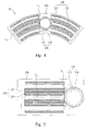
- Fig. 4 is a cross-sectional schematic view of another embodiment of the rotary motor of the invention.
- the rotary motor 100 comprises the rotor 110 and the stators 120.
- the rotor 110 has the shaft 112, and each of the stators 120 comprises the iron core 122 and the coil 124 wound around the iron core 122.
- the cross section of the iron core 122 perpendicular to the shaft 112 has the first axis L 1 being tangential to the shaft 112 and the second axis L 2 crossing the first axis L 1 .
- the rotor 110 is disposed on the extension line of the second axis L 2 of the stator 120.
- the quantity of the stators 120 is two.
- the cross section of each of the stators 120 perpendicular to the shaft 112 forms a curved shape (similar to a sector), and the two stators 120 are located respectively on two opposite sides of rotor 110, such that the two stators 120 and the rotor 110 there between form another curved structure (similar to a sector).
- the rotary motor 100 comprises the case 130, and the rotor 110 and the stators 120 are disposed in the case 130.
- the case 130 is also curved shape (similar to a sector), corresponding to the appearance of rotor 110 and stators 120.
- Fig. 5 is a cross-sectional schematic view of another embodiment of the rotary motor of the invention.
- the rotary motor 100 comprises the rotor 110 and the stator 120.
- the rotor 110 has the shaft 112, and the stator 120 comprises the iron core 122 and the coil 124 wound around the iron core 122.
- the cross section of the iron core 122 perpendicular to the shaft 112 has the first axis L 1 being tangential to the shaft 112 and the second axis L 2 crossing the first axis L 1 .
- the rotor 110 is disposed on the extension line of the second axis L 2 of the stator 120.
- the quantity of the stator 120 is one, and the length of the iron core 122 along the first axis L 1 can be shorter or larger than the length of the iron core 122 along the second axis L 2 .
- the shape of the cross section of the stator 120 perpendicular to the shaft 112 can be rectangular or curved.
- the stator 120 is disposed at a side of the rotor 110.
- the case 130 can be in a corresponding rectangular or curve shape.
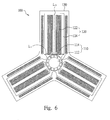
- Fig. 6 is a cross-sectional schematic view of yet another embodiment of the rotary motor of the invention.
- the rotary motor 100 comprises the rotor 110 and the stators 120.
- the rotor 110 has the shaft 112, and each of the stators 120 comprises the iron core 122 and the coil 124 wound around the iron core 122.
- the cross section of the iron core 122 perpendicular to the shaft 112 has the first axis L 1 being tangential to the shaft 112, and the second axis L 2 crossing the first axis L 1 .
- the rotor 110 is disposed on the extension line of the second axis L 2 of the stators 120.
- the cross section of the stators 120 perpendicular to the shaft 112 forms a rectangle, and the quantity of the stators 120 is three.
- Each of the stators 120 extends from the rotor 110 in a radial manner, and the angle between any two of the stators 120 that are adjacent to each other is about 120 degrees.
- the shape of the case 130 corresponding to the rotor 110 and the stators 120 corresponds to the combined shape of the rotor 110 and the stators 120 described above and shown in Fig. 6 .
- the rotary motor 100 provided in this invention can correspond to different requirements with respect to installation space.
- the shape of the stator(s) 120 and the relative positions of the stator(s) 120 and the rotor 110 can be changed for achieving a higher level of space utilization.
- the rotary motor 100 may have a bigger space for disposing the iron core 122 and the coil 124 to result in better electromechanical properties.
- a plurality of the rotary motors 100 mentioned above can be used in parallel, forming a relatively large power apparatus. Embodiments are illustrated and discussed below.
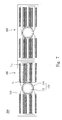
- Fig. 7 is a cross-sectional schematic view of an embodiment of a power apparatus of the invention.
- the power apparatus 200 comprises a plurality of the rotary motors 100 as shown in FIG. 2 , in which each rotary motor 100 comprises two stators 120 and one rotor 110.
- the cross section of the iron core 122 perpendicular to the rotor 110 has the first axis L 1 being tangential to the shaft, and the second axis L 2 crossing the first axis L 1 .
- the rotor 110 is located on the extension line of the second axis L 2 of the stators 120.
- the cross section of the two stators 120 perpendicular to the shaft 112 forms a rectangle, and the two stators 120 are located respectively on two opposite sides of the rotor 110.
- These rotary motors 100 can be arranged horizontally to thereby form the power apparatus 200 in a long strip configuration.
- the power apparatus 200 comprises a case 210, and the rotary motors 100 are disposed in the case 210
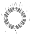
- Fig. 8 is a cross-sectional schematic view of another embodiment of the power apparatus of the invention.
- the power apparatus 200 comprises a plurality of the rotary motors 100 as shown in FIG. 4 , in which each rotary motor 100 comprises two stators 120 and one rotor 110.
- the cross section of the iron core 122 perpendicular to the rotor 110 has the first axis L 1 being tangential to the shaft 112, and the second axis L 2 crossing the first axis L 1 .
- the rotor 110 is located on the extension line of the second axis L 2 of stator 120.
- the cross section of the two stators 120 perpendicular to the shaft 112 forms a curve (similar to a sector), and the two stators 120 are located respectively on two sides of rotor 110.
- These rotary motors 100 can be arranged continuously in an end-to-end configuration to thereby form the power apparatus 200 in an annular shape.
- the case 210 of the power apparatus 200 can be a hollow ring, and the rotary motors 100 are disposed in the annular case 210.
- Fig. 9 and Fig. 10 are output torque diagrams of the power apparatus in FIG. 8 under different phase angle configurations.
- the output torque diagram of the power apparatus 200 is as shown in FIG. 9 , in which the output torque exhibits an obvious cogging force.
- this embodiment further adjusts the phase angle between each rotary motor 100, such that there are phase angle differences to reduce the generation of cogging force.
- the phase angle difference between each rotary motor 100 is the cycle of cogging force (electrical angle) divided by the number of rotary motors 100 arranged in parallel.
- the output torque diagram of the power apparatus 200 in FIG. 8 after such adjustment of phase angle is shown in FIG. 10 , in which the output torque does not exhibit any obvious cogging force.
- a plurality of the rotary motors 100 arranged in parallel can form another power apparatus 200, and persons of ordinary skill in the art should be able to vary the shape of the stators 120 and the arrangement among the rotary motors 100 according to actual requirements, so that space utilization is made more flexible.
- the phase angle among the rotary motors 100 can be adjusted to reduce the effect of cogging force.
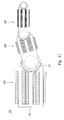
- Fig. 11 is a schematic diagram of an embodiment of a robot arm utilizing the rotary motor in FIG. 5 .
- the robot arm 300 comprises a plurality of the rotary motors 100 arranged in series, and each rotary motor 100 can provide an axial movement.
- a plurality of the rotary motors 100 can be arranged in series for allowing the robot arm 300 to undergo predetermined movements.
- each rotary motor 100 has only one stator 120 and one rotor 110, compared to traditional solutions using an annular iron core, the rotary motor 100 in this disclosure is light in weight and does not utilize a large space.
- the dimensions of the rotary motors 100 can be increasingly reduced in sequence from one end to the other end, such that the rotary motor 100 at the base of the robot arm 300 has the largest dimensions and the rotary motor 100 at the opposite end of the robot arm 300 has the smallest dimensions.
- the shape of the stator(s) and the relative positions of the stator(s) and the rotor of the rotary motor can be adjusted in the present disclosure, such that the rotary motor, and the power apparatus and the robot arm using the same may achieve a higher level of space utilization. Furthermore, a more flexible space utilization of the rotary motor, and the power apparatus and the robot arm using the same can be realized.
Landscapes
- Engineering & Computer Science (AREA)
- Power Engineering (AREA)
- Robotics (AREA)
- Mechanical Engineering (AREA)
- Iron Core Of Rotating Electric Machines (AREA)
- Permanent Magnet Type Synchronous Machine (AREA)
- Manipulator (AREA)
- Connection Of Motors, Electrical Generators, Mechanical Devices, And The Like (AREA)
Abstract
Description
- The present invention relates to robot arm technology. More particularly, the present invention relates to a rotary motor, a power apparatus, and a robot arm.
- The rotary motor is the main power source in electromechanical systems.
Fig. 1 is a schematic diagram of a traditional rotary motor. Therotary motor 10 includes arotor 20 and astator 30. Therotor 20 includes a magnet 22 and ashaft 24. Thestator 30 includes aniron core 32 and acoil 34. Theiron core 32 is in the form of an annulus, and therotor 20 is located in the central cavity of theannular iron core 32. Thus, therotary motor 10 is typically rectangular or a circular. - However, in the configuration of an electromechanical system, if the installation space for the rotary motor is neither rectangular nor circular, in use, limitations will be encountered with respect to the shape of the rotary motor, such that the utilization of the equipment space cannot be optimized.
- The present invention provides a rotary motor which optimizes the utilization of space.
- An aspect of the invention provides a rotary motor. The rotary motor includes a rotor and at least one stator. The rotor has a shaft. The stator has an iron core and a coil wound around the iron core, in which a cross section of the iron core perpendicular to the shaft has a long axis and a short axis, and the rotor is disposed on an extension line of the long axis.
- In one or more embodiments, the cross section can be rectangular or curved in shape.
- In one or more embodiments, the quantity of stators is two, and an angle between the stators is about 180 degrees.
- In one or more embodiments, the quantity of stators is three, and an angle between adjacent two of the stators is about 120 degrees.
- In one or more embodiments, the rotary motor further includes a case, and the stator and the rotor are located in the case.
- Another aspect of the invention provides a power apparatus. The power apparatus includes a plurality of rotary motors, in which each of the rotary motors includes a rotor and at least one stator. The rotor has a shaft. The stator has an iron core and a coil wound around the iron core, in which the cross section of the stator perpendicular to the shaft has a long axis and a short axis, and the rotor is disposed on the extension line of the long axis.
- In one or more embodiments, the cross section can be rectangular, and the rotary motors are in a horizontal arrangement.
- In one or more embodiments, the cross section can be curved in shape, and the rotary motors are in an annular arrangement.
- In one or more embodiments, the power apparatus further includes a case, and the rotary motors are disposed in the case.
- Another aspect of the invention provides a robot arm. The robot arm includes a series of a plurality of rotary motors aforementioned, in which the quantity of stator in each rotary motor is one, and the cross section of the stator rectangular in shape.
- In one or more embodiments, dimensions of the rotary motors can be increasingly reduced in sequence.
- The shape of the stator and the relative position of the stator and the rotor of the rotary motor can be adjusted in the present disclosure, such that the rotary motor, and the power apparatus and the robot arm using the same may achieve a higher level of space utilization. Furthermore, a more flexible space utilization of the rotary motor, and the power apparatus and the robot arm using the same can be realized.
- It is to be understood that both the foregoing general description and the following detailed description are by examples, and are intended to provide further explanation of the invention as claimed.
- The invention can be more fully understood by reading the following detailed description of the embodiment, with reference made to the accompanying drawings as follows:
-
Fig. 1 is a schematic diagram of a traditional rotary motor; -
Fig. 2-3 are cross-sectional schematic views of different embodiments of a rotary motor of the invention; -
Figs. 4-6 are cross-sectional schematic views of different embodiments of the rotary motor of the invention; -
Fig. 7 andFig. 8 are cross-sectional schematic views of different embodiments of a power apparatus of the invention; -
Fig. 9 and Fig. 10 are output torque diagrams of the power apparatus inFIG. 8 under different phase angle configurations; and -
Fig. 11 is a schematic diagram of an embodiment of a robot arm utilizing the rotary motor inFig. 5 . - Reference will now be made in detail to the present embodiments of the invention, examples of which are illustrated in the accompanying drawings. Wherever possible, the same reference numbers are used in the drawings and the description to refer to the same or like parts.
- The shape of a stator and the relative positions of the stator and a rotor of a rotary motor can be adjusted in the present disclosure, such that the rotary motor, and a power apparatus and a robot arm using the same may achieve a higher level of space utilization. Furthermore, a more flexible space utilization of the rotary motor, and the power apparatus and the robot arm using the same can be realized.
-
Fig. 2 is a cross-sectional schematic view of an embodiment of a rotary motor of the invention. Therotary motor 100 comprises arotor 110 and a plurality ofstators 120. Therotor 110 comprises ashaft 112 and a plurality ofmagnets 114, and themagnets 114 are disposed on the surface of theshaft 112 with the polarities staggered. The quantity of thestators 120 in this embodiment is two, and thestators 120 are located respectively on opposite sides of therotor 110. - Each of the
stators 120 comprises aniron core 122 and acoil 124 wound around theiron core 122. In this embodiment, therotary motor 100 is utilized in a 3-phase motor, and thus the quantity of magnetic poles of theiron core 120 and of thecorresponding coil 124 are both three. When electricity is supplied to thecoil 124 ofstator 120, magnetic forces are generated. Therotor 110 is rotated by the electromagnetic effect between thestator 120 and therotor 110. - Unlike traditional annular stators, the shape of each of the
stators 120 in this embodiment is rectangular, rather than annular. Specifically, theiron core 122 ofstator 120 has a first axis L1 and a second axis L2 in the cross section perpendicular to theshaft 112. The first axis L1 is tangential to theshaft 112. Namely, the first axis L1 is a straight line that touches the outside of a curve of theshaft 112 but does not cut across it. Furthermore, the first axis L1 is perpendicular to theiron core 122 at the terminals of the first axis L1. The second axis L2 crosses the first axis L1. The second axis L2 is perpendicular to theiron core 122 at the terminals of the second axis L2. In this embodiment, the second axis L2 and the first axis L1 are substantially perpendicular to each other, and the length of theiron core 122 along the first axis L1 is shorter than the length of theiron core 122 along the second axis L2. Therotor 110 is disposed on an extension line of the second axis L2. In this embodiment, the twostators 120 are located respectively on opposite sides of therotor 110, and the angle between the twostators 120 is about 180 degrees. The twostators 120 and therotor 110 are horizontally arranged to form a long strip. - The
rotary motor 100 further comprises acase 130 for matching with the design of thestator 120 and therotor 110. Corresponding to the formation of therotor 110 andstator 120 as a long strip, thecase 130 is also in the form of a long strip. In other words, therotary motor 100 is in the shape of a long strip in this embodiment for utilization in a long strip type of space. - The
rotary motor 100 may have different appearances by suitably changing the shape of thestators 120 and the relative positions of thestators 120 and therotor 110. Examples of various embodiments are illustrated and discussed below. -
Fig. 3 is a cross-sectional schematic view of another embodiment of the rotary motor of the invention. Therotary motor 100 comprises therotor 110 and thestators 120. Therotor 110 has theshaft 112, and each of thestators 120 comprises theiron core 122 and thecoil 124 wound around theiron core 122. The cross section of theiron core 122 perpendicular to theshaft 112 has the first axis L1 being tangential to theshaft 112, and the second axis L2 crossing the first axis L1. Therotor 110 is disposed on the extension line of the second axis L2 of thestator 120.
In this embodiment, twostators 120 are disposed at opposite sides of therotor 110. The first axis L1 is perpendicular to the second axis L2, and the length of theiron core 122 along the first axis L1 is longer than the length of theiron core 122 along the second axis L2.Fig. 4 is a cross-sectional schematic view of another embodiment of the rotary motor of the invention. Therotary motor 100 comprises therotor 110 and thestators 120. Therotor 110 has theshaft 112, and each of thestators 120 comprises theiron core 122 and thecoil 124 wound around theiron core 122. The cross section of theiron core 122 perpendicular to theshaft 112 has the first axis L1 being tangential to theshaft 112 and the second axis L2 crossing the first axis L1. Therotor 110 is disposed on the extension line of the second axis L2 of thestator 120. - In this embodiment, the quantity of the
stators 120 is two. The cross section of each of thestators 120 perpendicular to theshaft 112 forms a curved shape (similar to a sector), and the twostators 120 are located respectively on two opposite sides ofrotor 110, such that the twostators 120 and therotor 110 there between form another curved structure (similar to a sector). - The
rotary motor 100 comprises thecase 130, and therotor 110 and thestators 120 are disposed in thecase 130. Thecase 130 is also curved shape (similar to a sector), corresponding to the appearance ofrotor 110 andstators 120. -
Fig. 5 is a cross-sectional schematic view of another embodiment of the rotary motor of the invention. Therotary motor 100 comprises therotor 110 and thestator 120. Therotor 110 has theshaft 112, and thestator 120 comprises theiron core 122 and thecoil 124 wound around theiron core 122. The cross section of theiron core 122 perpendicular to theshaft 112 has the first axis L1 being tangential to theshaft 112 and the second axis L2 crossing the first axis L1. Therotor 110 is disposed on the extension line of the second axis L2 of thestator 120. - In this embodiment, the quantity of the
stator 120 is one, and the length of theiron core 122 along the first axis L1 can be shorter or larger than the length of theiron core 122 along the second axis L2. The shape of the cross section of thestator 120 perpendicular to theshaft 112 can be rectangular or curved. Thestator 120 is disposed at a side of therotor 110. Thecase 130 can be in a corresponding rectangular or curve shape. -
Fig. 6 is a cross-sectional schematic view of yet another embodiment of the rotary motor of the invention. Therotary motor 100 comprises therotor 110 and thestators 120. Therotor 110 has theshaft 112, and each of thestators 120 comprises theiron core 122 and thecoil 124 wound around theiron core 122. The cross section of theiron core 122 perpendicular to theshaft 112 has the first axis L1 being tangential to theshaft 112, and the second axis L2 crossing the first axis L1. Therotor 110 is disposed on the extension line of the second axis L2 of thestators 120. - In this embodiment, the cross section of the
stators 120 perpendicular to theshaft 112 forms a rectangle, and the quantity of thestators 120 is three. Each of thestators 120 extends from therotor 110 in a radial manner, and the angle between any two of thestators 120 that are adjacent to each other is about 120 degrees. The shape of thecase 130 corresponding to therotor 110 and thestators 120 corresponds to the combined shape of therotor 110 and thestators 120 described above and shown inFig. 6 . - As is evident from the embodiments mentioned above, the
rotary motor 100 provided in this invention can correspond to different requirements with respect to installation space. The shape of the stator(s) 120 and the relative positions of the stator(s) 120 and therotor 110 can be changed for achieving a higher level of space utilization. Furthermore, therotary motor 100 may have a bigger space for disposing theiron core 122 and thecoil 124 to result in better electromechanical properties. - Persons of ordinary skill in the art should be able to change the shape of the stator(s) 120 and the relative positions of the stator(s) 120 and the
rotor 110 according to actual requirements, and the present invention is not limited by the aforementioned embodiments. - Furthermore, a plurality of the
rotary motors 100 mentioned above can be used in parallel, forming a relatively large power apparatus. Embodiments are illustrated and discussed below. -
Fig. 7 is a cross-sectional schematic view of an embodiment of a power apparatus of the invention. Thepower apparatus 200 comprises a plurality of therotary motors 100 as shown inFIG. 2 , in which eachrotary motor 100 comprises twostators 120 and onerotor 110. The cross section of theiron core 122 perpendicular to therotor 110 has the first axis L1 being tangential to the shaft, and the second axis L2 crossing the first axis L1. Therotor 110 is located on the extension line of the second axis L2 of thestators 120. The cross section of the twostators 120 perpendicular to theshaft 112 forms a rectangle, and the twostators 120 are located respectively on two opposite sides of therotor 110. Theserotary motors 100 can be arranged horizontally to thereby form thepower apparatus 200 in a long strip configuration. Thepower apparatus 200 comprises acase 210, and therotary motors 100 are disposed in thecase 210. - Alternatively,
Fig. 8 is a cross-sectional schematic view of another embodiment of the power apparatus of the invention. Thepower apparatus 200 comprises a plurality of therotary motors 100 as shown inFIG. 4 , in which eachrotary motor 100 comprises twostators 120 and onerotor 110. The cross section of theiron core 122 perpendicular to therotor 110 has the first axis L1 being tangential to theshaft 112, and the second axis L2 crossing the first axis L1. Therotor 110 is located on the extension line of the second axis L2 ofstator 120. The cross section of the twostators 120 perpendicular to theshaft 112 forms a curve (similar to a sector), and the twostators 120 are located respectively on two sides ofrotor 110. Theserotary motors 100 can be arranged continuously in an end-to-end configuration to thereby form thepower apparatus 200 in an annular shape. Thecase 210 of thepower apparatus 200 can be a hollow ring, and therotary motors 100 are disposed in theannular case 210. -
Fig. 9 and Fig. 10 are output torque diagrams of the power apparatus inFIG. 8 under different phase angle configurations. When a plurality of therotary motors 100 are used to form thepower apparatus 200 as shown inFIG. 8 , if the phase angle among therotary motors 100 is not designed, such that all therotary motors 100 have the same phase angle, the output torque diagram of thepower apparatus 200 is as shown inFIG. 9 , in which the output torque exhibits an obvious cogging force. - Thus, this embodiment further adjusts the phase angle between each
rotary motor 100, such that there are phase angle differences to reduce the generation of cogging force. Specifically, the phase angle difference between eachrotary motor 100 is the cycle of cogging force (electrical angle) divided by the number ofrotary motors 100 arranged in parallel. The output torque diagram of thepower apparatus 200 inFIG. 8 after such adjustment of phase angle is shown inFIG. 10 , in which the output torque does not exhibit any obvious cogging force. - In summary, a plurality of the
rotary motors 100 arranged in parallel can form anotherpower apparatus 200, and persons of ordinary skill in the art should be able to vary the shape of thestators 120 and the arrangement among therotary motors 100 according to actual requirements, so that space utilization is made more flexible. The phase angle among therotary motors 100 can be adjusted to reduce the effect of cogging force. -
Fig. 11 is a schematic diagram of an embodiment of a robot arm utilizing the rotary motor inFIG. 5 . Therobot arm 300 comprises a plurality of therotary motors 100 arranged in series, and eachrotary motor 100 can provide an axial movement. A plurality of therotary motors 100 can be arranged in series for allowing therobot arm 300 to undergo predetermined movements. - Since each
rotary motor 100 has only onestator 120 and onerotor 110, compared to traditional solutions using an annular iron core, therotary motor 100 in this disclosure is light in weight and does not utilize a large space. In addition, for the reduction of weight at the end of therobot arm 300, the dimensions of therotary motors 100 can be increasingly reduced in sequence from one end to the other end, such that therotary motor 100 at the base of therobot arm 300 has the largest dimensions and therotary motor 100 at the opposite end of therobot arm 300 has the smallest dimensions. - The shape of the stator(s) and the relative positions of the stator(s) and the rotor of the rotary motor can be adjusted in the present disclosure, such that the rotary motor, and the power apparatus and the robot arm using the same may achieve a higher level of space utilization. Furthermore, a more flexible space utilization of the rotary motor, and the power apparatus and the robot arm using the same can be realized.
- Although the present invention has been described in considerable detail with reference to certain embodiments thereof, other embodiments are possible. Therefore, their spirit and scope of the appended claims should not be limited to the description of the embodiments contained herein.
- It will be apparent to those skilled in the art that various modifications and variations can be made to the structure of the present invention without departing from the scope or spirit of the invention. In view of the foregoing, it is intended that the present invention covers the modifications and variations of this invention provided they fall within the scope of the following claims.
Claims (14)
- A rotary motor, comprising:a rotor having a shaft; andat least one stator, each of the stator having an iron core and a coil wound around the iron core, wherein a cross section of the iron core perpendicular to the shaft has a first axis being tangential to the shaft, and a second axis crossing the first axis, and the rotor is disposed on an extension line of the second axis.
- The rotary motor of claim 1, wherein a quantity of the at least one stator is two, and an angle between the stators is about 180 degrees.
- The rotary motor of claim 1, wherein a quantity of the at least one stator is three, and an angle between adjacent two of the stators is about 120 degrees.
- The rotary motor of any one of claims 1-3, wherein the cross section is rectangular.
- The rotary motor of claim 1, wherein the cross section has a curved shape.
- The rotary motor of claim 1, wherein a length of the iron core along the first axis is shorter than a length of the iron core along the second axis.
- The rotary motor of claim 1, wherein a length of the iron core along the first axis is longer than a length of the iron core along the second axis.
- A power apparatus comprising a plurality of rotary motors, each of the rotary motors comprising:a rotor having a shaft, andat least one stator, each of the stator having an iron core and a coil wound around the iron core, wherein a cross section of the stator perpendicular to the shaft has a first axis being tangential to the shaft, and a second axis crossing the first axis, and the rotor is disposed on an extension line of the second axis.
- The power apparatus of claim 8, wherein the cross section is rectangular, and the rotary motors are in a horizontal arrangement.
- The power apparatus of claim 8, wherein the cross section has a curved shape, and the rotary motors are in an annular arrangement.
- The power apparatus of claim 8, wherein a length of the iron core along the first axis is shorter than a length of the iron core along the second axis.
- The power apparatus of claim 8, wherein a length of the iron core along the first axis is longer than a length of the iron core along the second axis.
- A robot arm comprising a plurality of the rotary motors of claim 1 arranged in series, wherein a quantity of the stator in each of the rotary motors is one, and the cross section of each of the stators is rectangular.
- The robot arm of claim 13, wherein dimensions of the rotary motors are increasingly reduced in sequence.
Applications Claiming Priority (2)
| Application Number | Priority Date | Filing Date | Title |
|---|---|---|---|
| TW102113278 | 2013-04-15 | ||
| TW103103387A TWI505604B (en) | 2013-04-15 | 2014-01-29 | Power apparatus |
Publications (3)
| Publication Number | Publication Date |
|---|---|
| EP2793380A2 true EP2793380A2 (en) | 2014-10-22 |
| EP2793380A3 EP2793380A3 (en) | 2017-11-08 |
| EP2793380B1 EP2793380B1 (en) | 2020-05-06 |
Family
ID=50349471
Family Applications (1)
| Application Number | Title | Priority Date | Filing Date |
|---|---|---|---|
| EP14160976.8A Active EP2793380B1 (en) | 2013-04-15 | 2014-03-20 | Robot arm |
Country Status (4)
| Country | Link |
|---|---|
| US (1) | US9579803B2 (en) |
| EP (1) | EP2793380B1 (en) |
| JP (1) | JP2014207851A (en) |
| TW (1) | TWI505604B (en) |
Cited By (1)
| Publication number | Priority date | Publication date | Assignee | Title |
|---|---|---|---|---|
| NO342487B1 (en) * | 2017-09-01 | 2018-05-28 | Frode Olsen | Motor / Generator / Machine component / Battery Cell. Unit with electronic transmission over several steps, from the units on both sides and towards the unit in the center. |
Families Citing this family (4)
| Publication number | Priority date | Publication date | Assignee | Title |
|---|---|---|---|---|
| US10170946B2 (en) * | 2015-02-02 | 2019-01-01 | Persimmon Technologies Corporation | Motor having non-circular stator |
| JP6791692B2 (en) * | 2016-09-16 | 2020-11-25 | 東芝ライフスタイル株式会社 | Electric blower |
| JP2022546945A (en) * | 2019-08-20 | 2022-11-10 | ハロディ ロボティクス アー/エス | Method and medium for cogging compensation of motor drive signals |
| DE102023123166A1 (en) * | 2022-09-05 | 2024-03-07 | Minebea Mitsumi Inc. | stator |
Family Cites Families (34)
| Publication number | Priority date | Publication date | Assignee | Title |
|---|---|---|---|---|
| US881585A (en) * | 1905-12-29 | 1908-03-10 | Mather & Platt Ltd | Electric motor. |
| US1723912A (en) * | 1928-02-15 | 1929-08-06 | Gen Electric | Dynamo-electric machine |
| JPH02164265A (en) * | 1988-09-13 | 1990-06-25 | Toshiba Corp | Variable void type motor |
| JPH0294439A (en) | 1988-09-29 | 1990-04-05 | Nec Corp | Manufacture of semiconductor device |
| JPH0294439U (en) * | 1989-01-11 | 1990-07-26 | ||
| JPH0319781A (en) * | 1989-06-14 | 1991-01-28 | Mitsubishi Electric Corp | Industrial robot device |
| TW212240B (en) * | 1991-03-19 | 1993-09-01 | Hitachi Seisakusyo Kk | |
| US5212418A (en) | 1992-04-20 | 1993-05-18 | Mason Elmer B | High torque and speed DC motors |
| JPH06290932A (en) * | 1993-03-31 | 1994-10-18 | Canon Inc | Base plate |
| CA2140950A1 (en) | 1994-02-22 | 1995-08-23 | Hung T. Du | Electric motor having permanent magnet brake |
| US5523662A (en) * | 1994-05-02 | 1996-06-04 | Engineering Services, Inc. | Modular, expandable and reconfigurable robot |
| KR0121122B1 (en) | 1994-06-29 | 1997-11-22 | 김광호 | Linear magnetoresistive motor |
| US5729071A (en) * | 1995-01-31 | 1998-03-17 | Steiner; Robert E. | Low cost multi-pole motor constructions and methods of manufacture |
| JPH08297930A (en) * | 1995-04-28 | 1996-11-12 | Fujitsu Ltd | Magnetic circuit structure of rotary actuator |
| FR2742940B1 (en) * | 1995-12-22 | 1998-03-13 | Moving Magnet Tech | DIPHASE MOTOR, IN PARTICULAR A WATCHMAKING MOTOR OR A MOTOR FOR DRIVING A DISPLAY HAND |
| FR2754953B1 (en) * | 1996-10-21 | 1999-02-26 | Moving Magnet Tech | POLYPHASE MOTOR, PARTICULARLY FOR DRIVING A DISPLAY HAND |
| TW380329B (en) | 1997-04-16 | 2000-01-21 | Japan Servo | Permanent-magnet revolving electrodynamic machine with a concentrated winding stator |
| JP3613994B2 (en) | 1998-02-12 | 2005-01-26 | トヨタ自動車株式会社 | Flat wire coil manufacturing apparatus and flat wire coil manufacturing method |
| JP2000324775A (en) * | 1999-04-30 | 2000-11-24 | Morita Mfg Co Ltd | Small motor and small cutting device |
| WO2001045235A1 (en) | 1999-12-17 | 2001-06-21 | MONEGO, Guido | Electronically controlled permanent-magnet electric motor |
| JP2002136090A (en) * | 2000-10-30 | 2002-05-10 | Matsushita Electric Ind Co Ltd | Brushless motor |
| DE10121907B4 (en) * | 2001-05-03 | 2008-02-21 | Saia-Burgess Ozd Kft. | Multi-shaft motor and actuator |
| JP4333979B2 (en) | 2002-08-09 | 2009-09-16 | 日本トムソン株式会社 | Alignment stage device with built-in linear motor |
| JP4283618B2 (en) * | 2003-08-29 | 2009-06-24 | セイコープレシジョン株式会社 | Electromagnetic actuator |
| US7078843B2 (en) | 2003-09-05 | 2006-07-18 | Black & Decker Inc. | Field assemblies and methods of making same |
| JP4041443B2 (en) | 2003-09-16 | 2008-01-30 | 本田技研工業株式会社 | Claw pole motor stator |
| JP2005341704A (en) * | 2004-05-27 | 2005-12-08 | Seiko Precision Inc | Stator for motor, motor including the stator, and sector drive unit equipped with the motor |
| US8084913B2 (en) * | 2005-10-06 | 2011-12-27 | Borgwarner Inc. | DC motor with asymmetrical poles |
| JP4735210B2 (en) * | 2005-11-28 | 2011-07-27 | パナソニック株式会社 | motor |
| US7372179B2 (en) * | 2005-12-10 | 2008-05-13 | Lee Chung Chiang | Stepper motor having solenoid coils around end portions of stator poles |
| JP2010288426A (en) | 2009-06-15 | 2010-12-24 | Tamron Co Ltd | Three-phase dc motor |
| CN203368163U (en) * | 2010-08-26 | 2013-12-25 | 三菱电机株式会社 | Rotating electrical machines and stator core manufacturing apparatus for manufacturing stator cores thereof |
| JP2012147541A (en) * | 2011-01-11 | 2012-08-02 | Seiko Epson Corp | Electromechanical device, and actuator, motor, robot, and robot hand using the same |
| JP2013013964A (en) | 2011-07-04 | 2013-01-24 | Seiko Epson Corp | Robot, and method for controlling robot |
-
2014
- 2014-01-29 TW TW103103387A patent/TWI505604B/en active
- 2014-03-20 EP EP14160976.8A patent/EP2793380B1/en active Active
- 2014-03-25 US US14/224,131 patent/US9579803B2/en active Active
- 2014-04-03 JP JP2014077129A patent/JP2014207851A/en active Pending
Non-Patent Citations (1)
| Title |
|---|
| None |
Cited By (2)
| Publication number | Priority date | Publication date | Assignee | Title |
|---|---|---|---|---|
| NO342487B1 (en) * | 2017-09-01 | 2018-05-28 | Frode Olsen | Motor / Generator / Machine component / Battery Cell. Unit with electronic transmission over several steps, from the units on both sides and towards the unit in the center. |
| NO20171419A1 (en) * | 2017-09-01 | 2018-05-28 | Frode Olsen | Engine / Generator / Machine part / Battery cell. Unit with electronic gearing over several steps, from the units on both sides, and towards the unit in the center. |
Also Published As
| Publication number | Publication date |
|---|---|
| TW201440387A (en) | 2014-10-16 |
| JP2014207851A (en) | 2014-10-30 |
| EP2793380B1 (en) | 2020-05-06 |
| US20140305246A1 (en) | 2014-10-16 |
| US9579803B2 (en) | 2017-02-28 |
| TWI505604B (en) | 2015-10-21 |
| EP2793380A3 (en) | 2017-11-08 |
Similar Documents
| Publication | Publication Date | Title |
|---|---|---|
| US7960887B2 (en) | Permanent-magnet switched-flux machine | |
| KR101492172B1 (en) | Radial and Axial Flux Motor using Integrated Windings | |
| JP6223835B2 (en) | Axial gap type motor | |
| Yu et al. | A dual notched design of radial-flux permanent magnet motors with low cogging torque and rare earth material | |
| US9579803B2 (en) | Power apparatus having plural rotary motors | |
| EP2101397A3 (en) | Electric motor | |
| EP2800257A1 (en) | Electromagnetic generator | |
| CN106787306B (en) | A Radial Segmented Modular Switching Flux Disc Motor | |
| CN102013739B (en) | Hal-Bach permanent magnet actuator capable of lineally rotating two degrees of freedom | |
| CN109716621B (en) | Complementary unidirectional magnetic rotor/stator assembly pair | |
| CN111525772B (en) | A tooth-cutting permanent magnet linear motor | |
| CN103765734B (en) | power generation turbine | |
| CN107493004A (en) | A kind of modularization cylindrical permanent linear synchronous motor | |
| CN105553148A (en) | Rotation shaft deflection type permanent magnet power generator | |
| CN108494211B (en) | Axial flux permanent magnet synchronous reluctance motor | |
| CN201758314U (en) | Motor with multipolar wiring device | |
| JP2017212762A (en) | Brushless motor | |
| KR101584160B1 (en) | Electric motor producing high torque | |
| EP2712055A1 (en) | Heterogeneous motor | |
| WO2020245392A1 (en) | An electrical machine comprising an integrated magnetic torsion spring | |
| CN104104160A (en) | Rotating motors, power units and robotic arms | |
| US8487486B1 (en) | Folded electromagnetic coil | |
| KR20180043104A (en) | motor | |
| KR101671841B1 (en) | Rotor structure in permanent magnet motor | |
| JP2014207844A (en) | Structure of electric generator/motor |
Legal Events
| Date | Code | Title | Description |
|---|---|---|---|
| PUAI | Public reference made under article 153(3) epc to a published international application that has entered the european phase |
Free format text: ORIGINAL CODE: 0009012 |
|
| 17P | Request for examination filed |
Effective date: 20140320 |
|
| AK | Designated contracting states |
Kind code of ref document: A2 Designated state(s): AL AT BE BG CH CY CZ DE DK EE ES FI FR GB GR HR HU IE IS IT LI LT LU LV MC MK MT NL NO PL PT RO RS SE SI SK SM TR |
|
| AX | Request for extension of the european patent |
Extension state: BA ME |
|
| REG | Reference to a national code |
Ref country code: DE Ref legal event code: R079 Ref document number: 602014064821 Country of ref document: DE Free format text: PREVIOUS MAIN CLASS: H02K0021180000 Ipc: B25J0009120000 |
|
| PUAL | Search report despatched |
Free format text: ORIGINAL CODE: 0009013 |
|
| AK | Designated contracting states |
Kind code of ref document: A3 Designated state(s): AL AT BE BG CH CY CZ DE DK EE ES FI FR GB GR HR HU IE IS IT LI LT LU LV MC MK MT NL NO PL PT RO RS SE SI SK SM TR |
|
| AX | Request for extension of the european patent |
Extension state: BA ME |
|
| RIC1 | Information provided on ipc code assigned before grant |
Ipc: B25J 9/12 20060101AFI20170929BHEP Ipc: H02K 16/00 20060101ALI20170929BHEP Ipc: H02K 16/02 20060101ALI20170929BHEP Ipc: H02K 1/14 20060101ALI20170929BHEP Ipc: H02K 21/14 20060101ALI20170929BHEP |
|
| STAA | Information on the status of an ep patent application or granted ep patent |
Free format text: STATUS: EXAMINATION IS IN PROGRESS |
|
| 17Q | First examination report despatched |
Effective date: 20181220 |
|
| GRAP | Despatch of communication of intention to grant a patent |
Free format text: ORIGINAL CODE: EPIDOSNIGR1 |
|
| STAA | Information on the status of an ep patent application or granted ep patent |
Free format text: STATUS: GRANT OF PATENT IS INTENDED |
|
| INTG | Intention to grant announced |
Effective date: 20200103 |
|
| GRAS | Grant fee paid |
Free format text: ORIGINAL CODE: EPIDOSNIGR3 |
|
| GRAA | (expected) grant |
Free format text: ORIGINAL CODE: 0009210 |
|
| STAA | Information on the status of an ep patent application or granted ep patent |
Free format text: STATUS: THE PATENT HAS BEEN GRANTED |
|
| AK | Designated contracting states |
Kind code of ref document: B1 Designated state(s): AL AT BE BG CH CY CZ DE DK EE ES FI FR GB GR HR HU IE IS IT LI LT LU LV MC MK MT NL NO PL PT RO RS SE SI SK SM TR |
|
| REG | Reference to a national code |
Ref country code: GB Ref legal event code: FG4D |
|
| REG | Reference to a national code |
Ref country code: CH Ref legal event code: EP Ref country code: AT Ref legal event code: REF Ref document number: 1266031 Country of ref document: AT Kind code of ref document: T Effective date: 20200515 |
|
| REG | Reference to a national code |
Ref country code: IE Ref legal event code: FG4D Ref country code: NL Ref legal event code: FP |
|
| REG | Reference to a national code |
Ref country code: DE Ref legal event code: R096 Ref document number: 602014064821 Country of ref document: DE |
|
| REG | Reference to a national code |
Ref country code: LT Ref legal event code: MG4D |
|
| PG25 | Lapsed in a contracting state [announced via postgrant information from national office to epo] |
Ref country code: GR Free format text: LAPSE BECAUSE OF FAILURE TO SUBMIT A TRANSLATION OF THE DESCRIPTION OR TO PAY THE FEE WITHIN THE PRESCRIBED TIME-LIMIT Effective date: 20200807 Ref country code: NO Free format text: LAPSE BECAUSE OF FAILURE TO SUBMIT A TRANSLATION OF THE DESCRIPTION OR TO PAY THE FEE WITHIN THE PRESCRIBED TIME-LIMIT Effective date: 20200806 Ref country code: FI Free format text: LAPSE BECAUSE OF FAILURE TO SUBMIT A TRANSLATION OF THE DESCRIPTION OR TO PAY THE FEE WITHIN THE PRESCRIBED TIME-LIMIT Effective date: 20200506 Ref country code: IS Free format text: LAPSE BECAUSE OF FAILURE TO SUBMIT A TRANSLATION OF THE DESCRIPTION OR TO PAY THE FEE WITHIN THE PRESCRIBED TIME-LIMIT Effective date: 20200906 Ref country code: PT Free format text: LAPSE BECAUSE OF FAILURE TO SUBMIT A TRANSLATION OF THE DESCRIPTION OR TO PAY THE FEE WITHIN THE PRESCRIBED TIME-LIMIT Effective date: 20200907 Ref country code: SE Free format text: LAPSE BECAUSE OF FAILURE TO SUBMIT A TRANSLATION OF THE DESCRIPTION OR TO PAY THE FEE WITHIN THE PRESCRIBED TIME-LIMIT Effective date: 20200506 Ref country code: LT Free format text: LAPSE BECAUSE OF FAILURE TO SUBMIT A TRANSLATION OF THE DESCRIPTION OR TO PAY THE FEE WITHIN THE PRESCRIBED TIME-LIMIT Effective date: 20200506 |
|
| PG25 | Lapsed in a contracting state [announced via postgrant information from national office to epo] |
Ref country code: RS Free format text: LAPSE BECAUSE OF FAILURE TO SUBMIT A TRANSLATION OF THE DESCRIPTION OR TO PAY THE FEE WITHIN THE PRESCRIBED TIME-LIMIT Effective date: 20200506 Ref country code: BG Free format text: LAPSE BECAUSE OF FAILURE TO SUBMIT A TRANSLATION OF THE DESCRIPTION OR TO PAY THE FEE WITHIN THE PRESCRIBED TIME-LIMIT Effective date: 20200806 Ref country code: LV Free format text: LAPSE BECAUSE OF FAILURE TO SUBMIT A TRANSLATION OF THE DESCRIPTION OR TO PAY THE FEE WITHIN THE PRESCRIBED TIME-LIMIT Effective date: 20200506 Ref country code: HR Free format text: LAPSE BECAUSE OF FAILURE TO SUBMIT A TRANSLATION OF THE DESCRIPTION OR TO PAY THE FEE WITHIN THE PRESCRIBED TIME-LIMIT Effective date: 20200506 |
|
| REG | Reference to a national code |
Ref country code: AT Ref legal event code: MK05 Ref document number: 1266031 Country of ref document: AT Kind code of ref document: T Effective date: 20200506 |
|
| PG25 | Lapsed in a contracting state [announced via postgrant information from national office to epo] |
Ref country code: AL Free format text: LAPSE BECAUSE OF FAILURE TO SUBMIT A TRANSLATION OF THE DESCRIPTION OR TO PAY THE FEE WITHIN THE PRESCRIBED TIME-LIMIT Effective date: 20200506 |
|
| PG25 | Lapsed in a contracting state [announced via postgrant information from national office to epo] |
Ref country code: ES Free format text: LAPSE BECAUSE OF FAILURE TO SUBMIT A TRANSLATION OF THE DESCRIPTION OR TO PAY THE FEE WITHIN THE PRESCRIBED TIME-LIMIT Effective date: 20200506 Ref country code: DK Free format text: LAPSE BECAUSE OF FAILURE TO SUBMIT A TRANSLATION OF THE DESCRIPTION OR TO PAY THE FEE WITHIN THE PRESCRIBED TIME-LIMIT Effective date: 20200506 Ref country code: EE Free format text: LAPSE BECAUSE OF FAILURE TO SUBMIT A TRANSLATION OF THE DESCRIPTION OR TO PAY THE FEE WITHIN THE PRESCRIBED TIME-LIMIT Effective date: 20200506 Ref country code: IT Free format text: LAPSE BECAUSE OF FAILURE TO SUBMIT A TRANSLATION OF THE DESCRIPTION OR TO PAY THE FEE WITHIN THE PRESCRIBED TIME-LIMIT Effective date: 20200506 Ref country code: AT Free format text: LAPSE BECAUSE OF FAILURE TO SUBMIT A TRANSLATION OF THE DESCRIPTION OR TO PAY THE FEE WITHIN THE PRESCRIBED TIME-LIMIT Effective date: 20200506 Ref country code: SM Free format text: LAPSE BECAUSE OF FAILURE TO SUBMIT A TRANSLATION OF THE DESCRIPTION OR TO PAY THE FEE WITHIN THE PRESCRIBED TIME-LIMIT Effective date: 20200506 Ref country code: RO Free format text: LAPSE BECAUSE OF FAILURE TO SUBMIT A TRANSLATION OF THE DESCRIPTION OR TO PAY THE FEE WITHIN THE PRESCRIBED TIME-LIMIT Effective date: 20200506 Ref country code: CZ Free format text: LAPSE BECAUSE OF FAILURE TO SUBMIT A TRANSLATION OF THE DESCRIPTION OR TO PAY THE FEE WITHIN THE PRESCRIBED TIME-LIMIT Effective date: 20200506 |
|
| REG | Reference to a national code |
Ref country code: DE Ref legal event code: R097 Ref document number: 602014064821 Country of ref document: DE |
|
| PG25 | Lapsed in a contracting state [announced via postgrant information from national office to epo] |
Ref country code: SK Free format text: LAPSE BECAUSE OF FAILURE TO SUBMIT A TRANSLATION OF THE DESCRIPTION OR TO PAY THE FEE WITHIN THE PRESCRIBED TIME-LIMIT Effective date: 20200506 Ref country code: PL Free format text: LAPSE BECAUSE OF FAILURE TO SUBMIT A TRANSLATION OF THE DESCRIPTION OR TO PAY THE FEE WITHIN THE PRESCRIBED TIME-LIMIT Effective date: 20200506 |
|
| PLBE | No opposition filed within time limit |
Free format text: ORIGINAL CODE: 0009261 |
|
| STAA | Information on the status of an ep patent application or granted ep patent |
Free format text: STATUS: NO OPPOSITION FILED WITHIN TIME LIMIT |
|
| 26N | No opposition filed |
Effective date: 20210209 |
|
| PG25 | Lapsed in a contracting state [announced via postgrant information from national office to epo] |
Ref country code: SI Free format text: LAPSE BECAUSE OF FAILURE TO SUBMIT A TRANSLATION OF THE DESCRIPTION OR TO PAY THE FEE WITHIN THE PRESCRIBED TIME-LIMIT Effective date: 20200506 |
|
| PG25 | Lapsed in a contracting state [announced via postgrant information from national office to epo] |
Ref country code: MC Free format text: LAPSE BECAUSE OF FAILURE TO SUBMIT A TRANSLATION OF THE DESCRIPTION OR TO PAY THE FEE WITHIN THE PRESCRIBED TIME-LIMIT Effective date: 20200506 |
|
| REG | Reference to a national code |
Ref country code: CH Ref legal event code: PL |
|
| GBPC | Gb: european patent ceased through non-payment of renewal fee |
Effective date: 20210320 |
|
| REG | Reference to a national code |
Ref country code: BE Ref legal event code: MM Effective date: 20210331 |
|
| PG25 | Lapsed in a contracting state [announced via postgrant information from national office to epo] |
Ref country code: IE Free format text: LAPSE BECAUSE OF NON-PAYMENT OF DUE FEES Effective date: 20210320 Ref country code: FR Free format text: LAPSE BECAUSE OF NON-PAYMENT OF DUE FEES Effective date: 20210331 Ref country code: GB Free format text: LAPSE BECAUSE OF NON-PAYMENT OF DUE FEES Effective date: 20210320 Ref country code: CH Free format text: LAPSE BECAUSE OF NON-PAYMENT OF DUE FEES Effective date: 20210331 Ref country code: LI Free format text: LAPSE BECAUSE OF NON-PAYMENT OF DUE FEES Effective date: 20210331 Ref country code: LU Free format text: LAPSE BECAUSE OF NON-PAYMENT OF DUE FEES Effective date: 20210320 |
|
| PG25 | Lapsed in a contracting state [announced via postgrant information from national office to epo] |
Ref country code: BE Free format text: LAPSE BECAUSE OF NON-PAYMENT OF DUE FEES Effective date: 20210331 |
|
| PG25 | Lapsed in a contracting state [announced via postgrant information from national office to epo] |
Ref country code: HU Free format text: LAPSE BECAUSE OF FAILURE TO SUBMIT A TRANSLATION OF THE DESCRIPTION OR TO PAY THE FEE WITHIN THE PRESCRIBED TIME-LIMIT; INVALID AB INITIO Effective date: 20140320 |
|
| PG25 | Lapsed in a contracting state [announced via postgrant information from national office to epo] |
Ref country code: CY Free format text: LAPSE BECAUSE OF FAILURE TO SUBMIT A TRANSLATION OF THE DESCRIPTION OR TO PAY THE FEE WITHIN THE PRESCRIBED TIME-LIMIT Effective date: 20200506 |
|
| PG25 | Lapsed in a contracting state [announced via postgrant information from national office to epo] |
Ref country code: MK Free format text: LAPSE BECAUSE OF FAILURE TO SUBMIT A TRANSLATION OF THE DESCRIPTION OR TO PAY THE FEE WITHIN THE PRESCRIBED TIME-LIMIT Effective date: 20200506 |
|
| PG25 | Lapsed in a contracting state [announced via postgrant information from national office to epo] |
Ref country code: MT Free format text: LAPSE BECAUSE OF FAILURE TO SUBMIT A TRANSLATION OF THE DESCRIPTION OR TO PAY THE FEE WITHIN THE PRESCRIBED TIME-LIMIT Effective date: 20200506 |
|
| PG25 | Lapsed in a contracting state [announced via postgrant information from national office to epo] |
Ref country code: TR Free format text: LAPSE BECAUSE OF FAILURE TO SUBMIT A TRANSLATION OF THE DESCRIPTION OR TO PAY THE FEE WITHIN THE PRESCRIBED TIME-LIMIT Effective date: 20200506 |
|
| PGFP | Annual fee paid to national office [announced via postgrant information from national office to epo] |
Ref country code: DE Payment date: 20260327 Year of fee payment: 13 |
|
| PGFP | Annual fee paid to national office [announced via postgrant information from national office to epo] |
Ref country code: NL Payment date: 20260326 Year of fee payment: 13 |