EP2793341A1 - System for prevention of and protection against fire due to fuse misuse - Google Patents
System for prevention of and protection against fire due to fuse misuse Download PDFInfo
- Publication number
- EP2793341A1 EP2793341A1 EP11877345.6A EP11877345A EP2793341A1 EP 2793341 A1 EP2793341 A1 EP 2793341A1 EP 11877345 A EP11877345 A EP 11877345A EP 2793341 A1 EP2793341 A1 EP 2793341A1
- Authority
- EP
- European Patent Office
- Prior art keywords
- fuse
- load
- capacity
- slow blow
- misuse
- Prior art date
- Legal status (The legal status is an assumption and is not a legal conclusion. Google has not performed a legal analysis and makes no representation as to the accuracy of the status listed.)
- Withdrawn
Links
- 230000002265 prevention Effects 0.000 title claims description 15
- 230000008018 melting Effects 0.000 claims description 14
- 238000002844 melting Methods 0.000 claims description 14
- 230000005611 electricity Effects 0.000 claims description 5
- 239000002184 metal Substances 0.000 claims description 4
- 239000012780 transparent material Substances 0.000 claims description 4
- 230000004048 modification Effects 0.000 abstract description 10
- 238000012986 modification Methods 0.000 abstract description 10
- 238000010586 diagram Methods 0.000 description 3
- 238000005476 soldering Methods 0.000 description 2
- 230000002159 abnormal effect Effects 0.000 description 1
- 238000010276 construction Methods 0.000 description 1
- 230000000694 effects Effects 0.000 description 1
- 239000011521 glass Substances 0.000 description 1
Images
Classifications
-
- H—ELECTRICITY
- H01—ELECTRIC ELEMENTS
- H01H—ELECTRIC SWITCHES; RELAYS; SELECTORS; EMERGENCY PROTECTIVE DEVICES
- H01H85/00—Protective devices in which the current flows through a part of fusible material and this current is interrupted by displacement of the fusible material when this current becomes excessive
- H01H85/02—Details
- H01H85/22—Intermediate or auxiliary parts for carrying, holding, or retaining fuse, co-operating with base or fixed holder, and removable therefrom for renewing the fuse
-
- H—ELECTRICITY
- H01—ELECTRIC ELEMENTS
- H01H—ELECTRIC SWITCHES; RELAYS; SELECTORS; EMERGENCY PROTECTIVE DEVICES
- H01H37/00—Thermally-actuated switches
- H01H37/74—Switches in which only the opening movement or only the closing movement of a contact is effected by heating or cooling
- H01H37/76—Contact member actuated by melting of fusible material, actuated due to burning of combustible material or due to explosion of explosive material
-
- H—ELECTRICITY
- H01—ELECTRIC ELEMENTS
- H01H—ELECTRIC SWITCHES; RELAYS; SELECTORS; EMERGENCY PROTECTIVE DEVICES
- H01H85/00—Protective devices in which the current flows through a part of fusible material and this current is interrupted by displacement of the fusible material when this current becomes excessive
- H01H85/02—Details
-
- H—ELECTRICITY
- H02—GENERATION; CONVERSION OR DISTRIBUTION OF ELECTRIC POWER
- H02H—EMERGENCY PROTECTIVE CIRCUIT ARRANGEMENTS
- H02H3/00—Emergency protective circuit arrangements for automatic disconnection directly responsive to an undesired change from normal electric working condition with or without subsequent reconnection ; integrated protection
- H02H3/02—Details
- H02H3/05—Details with means for increasing reliability, e.g. redundancy arrangements
-
- H—ELECTRICITY
- H02—GENERATION; CONVERSION OR DISTRIBUTION OF ELECTRIC POWER
- H02H—EMERGENCY PROTECTIVE CIRCUIT ARRANGEMENTS
- H02H3/00—Emergency protective circuit arrangements for automatic disconnection directly responsive to an undesired change from normal electric working condition with or without subsequent reconnection ; integrated protection
- H02H3/08—Emergency protective circuit arrangements for automatic disconnection directly responsive to an undesired change from normal electric working condition with or without subsequent reconnection ; integrated protection responsive to excess current
-
- H—ELECTRICITY
- H01—ELECTRIC ELEMENTS
- H01H—ELECTRIC SWITCHES; RELAYS; SELECTORS; EMERGENCY PROTECTIVE DEVICES
- H01H85/00—Protective devices in which the current flows through a part of fusible material and this current is interrupted by displacement of the fusible material when this current becomes excessive
- H01H85/02—Details
- H01H85/24—Means for preventing insertion of incorrect fuse
Definitions
- the present invention relates to a system for prevention of and protection against a fire caused by fuse misuse. More particularly, the present invention relates to a system for prevention of and protection against a fire caused by fuse misuse, in which if a user who does not know an electric circuit well uses a high capacity fuse connected to an excessive electrical load, an overcurrent flowing to the wring exceeds a permissible capacity of the wiring, and in order to prevent this from occurring, a slow blow fuse designed to be blown out more slowly than a normal fuse is installed at a rear end of the high capacity fuse so that the machine can be protected from a risk of a damage and of a fire of the wiring caused by an electrical overload due to fuse misuse and faulty circuit modification.
- a convention general electric power circuit is configured such that electricity from a battery is supplied to a load via a fuse, and the fuse is blown out if an abnormal state such as short-circuit occurs in the load as shown in Fig. 1 .
- the present invention has been made to solve the aforementioned problem occurring in the prior art, and it is an object of the present invention to provide a system for prevention of and protection against a fire caused by fuse misuse, in which the machine can be protected from a risk of a damage and of a fire of the wiring caused by an electrical overload due to fuse misuse and faulty circuit modification.
- a system for prevention of and protection against a fire caused by fuse misuse in accordance with an embodiment of the present invention in accordance with an embodiment of the present invention is configured such that if a user who does not know an electric circuit well uses a high capacity fuse connected to an excessive electrical load, an overcurrent flowing to the wring exceeds a permissible capacity of the wiring, and in order to prevent this from occurring, a slow blow fuse designed to be blown out more slowly than a normal fuse is installed at a rear end of the high capacity fuse so that the machine can be protected from a risk of a damage and of a fire of the wiring caused by an electrical overload due to fuse misuse and faulty circuit modification.
- the present invention provides a system for prevention of and protection against a fire caused by fuse misuse, comprising a load and a high breaking capacity fuse having a rated capacity higher than that of a normal fuse that is installed to be suit to the capacity of the load, wherein the improvement comprises a slow blow fuse installed between the high breaking capacity fuse and the load and having a melting part that is melted to be broken due to a temperature rise when an overcurrent having passed through the high breaking capacity fuse is applied to the slow blow fuse to interrupt the overcurrent flowing to the load.
- the load may be any one selected from among a lamp installed on a boom or an operator's cab, a wiper motor, a fan motor, and a machine controller.
- the slow blow fuse may include: an element made of a metal to enable electricity to flow therethrough; a housing configured to securely fix the element; a cover made of a transparent material to allow the state of the fuse to be confirmed therethrough; and the melting part positioned on the element inside the housing without being in close contact with the housing and the cover, the melting part being melted to be broken due to a temperature rise when the overcurrent flows therethrough.
- the system for prevention of and protection against a fire caused by fuse misuse in accordance with an embodiment of the present invention as constructed above has the following advantages.
- the present invention enables the machine to be protected from a risk of a damage and of a fire of the wiring caused by an electrical overload due to fuse misuse and faulty circuit modification.
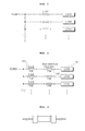
- Fig. 2 is a schematic block diagram showing a system for prevention of and protection against a fire caused by fuse misuse in accordance with an embodiment of the present invention
- the system according to the present invention is configured such that a slow blow fuse 103 designed to be blown out more slowly than a normal fuse is installed at a rear end of the high capacity fuse so that the machine can be protected from a risk of a damage and of a fire of the wiring caused by an electrical overload due to fuse misuse and faulty circuit modification.
- a slow blow fuse 103 is installed between the high breaking capacity fuse 101 and the load 102.
- a slow blow fuse 103 is installed between the high breaking capacity fuse 101 and the load 102 and has a melting part that is melted to be broken due to a temperature rise when an overcurrent having passed through the high breaking capacity fuse 101 is applied to the slow blow fuse 103 to interrupt the overcurrent flowing to the load 102.
- a high breaking capacity fuse having a rated capacity of 20A is used in a state of being connected to a load, when an overcurrent flows to the load, it exceeds a permissible capacity range of the wiring designed to be suited to both the existing normal fuse having the rated capacity of 15A and the load, so that the high breaking capacity fuse is not blown out but the wiring is burnt.
- the present invention provides a system in which a slow blow fuse 103 is installed at a rear end of the high breaking capacity fuse so that when an overcurrent exceeding a maximum design capacity flows to the wiring, the slow blow fuse 103 is caused to be blown out, thereby preventing a dangerous situation such a fire or the like that may occurs additionally.
- a slow blow fuse 103 is installed between the high breaking capacity fuse 101 and the load 102 and has a melting part that is melted to be broken due to a temperature rise when an overcurrent having passed through the high breaking capacity fuse 101 is applied to the slow blow fuse 103 to interrupt the overcurrent flowing to the load 102.
- the system according to the present invention has a structure in which the slow blow fuse 103 is installed between the load 102 and the high breaking capacity fuse 101 having a rated capacity higher than that of a normal fuse that is installed to be suit to the capacity of the load 102, and a melting part is melted to be broken due to a temperature rise when an overcurrent having passed through the high breaking capacity fuse 101 is applied to the slow blow fuse 103 to interrupt the overcurrent flowing to the load 102.
- the slow blow fuse 103 may include: an element made of a metal to enable electricity to flow therethrough; a housing configured to securely fix the element; a cover made of a transparent material to allow the state of the fuse to be confirmed therethrough; and the melting part positioned on the element inside the housing without being in close contact with the housing and the cover, the melting part being melted to be broken due to a temperature rise when the overcurrent flows therethrough.
- the load 102 that is connected to a rear end of the flow blow fuse 103 may be any one selected from among a lamp installed on a boom or an operator's cab, a wiper motor, a fan motor, and a machine controller.
- the operation of the inventive system is performed in such a manner that the slow blow fuse 103 is installed between the load 102 and the high breaking capacity fuse 101 having a rated capacity higher than that of a normal fuse that is installed to be suit to the capacity of the load 102, so that the melting part is melted to be broken due to a temperature rise when an overcurrent having passed through the high breaking capacity fuse 101 is applied to the slow blow fuse 103 to interrupt the overcurrent flowing to the load 102.
- a high breaking capacity fuse having a rated capacity of 20A is used in a state of being connected to a load, when an overcurrent flows to the load, it exceeds a permissible capacity range of the wiring designed to be suited to both the existing normal fuse having the rated capacity of 15A and the load, so that the high breaking capacity fuse is not blown out but the wiring is burnt.
- the present invention provides a system in which a slow blow fuse 103 is installed at a rear end of the high breaking capacity fuse so that when an overcurrent exceeding a maximum design capacity flows to the wiring, the slow blow fuse 103 is caused to be blown out, thereby preventing a dangerous situation such a fire or the like that may occurs additionally.
- the slow blow fuse 103 may include: an element made of a metal to enable electricity to flow therethrough; a housing configured to securely fix the element; a cover made of a transparent material to allow the state of the fuse to be confirmed therethrough; and the melting part positioned on the element inside the housing without being in close contact with the housing and the cover, the melting part being melted to be broken due to a temperature rise when the overcurrent flows therethrough.
- Fig. 3 is a perspective view showing an example of a slow blow fuse that can be used in the present invention.
- the slow blow fuse that can be used in the present invention is a small-sized fuse developed in the form of a glass or chip.
- the slow blow fuse designed to be capable of being mounted on a PCB, and thus it is impossible for a user to easily change the slow blow fuse. For this reason, if a user who is not an expert change the slow blow fuse easily, there is a risk of misuse of the slow blow fuse.
- the slow blow fuse that can be used in the present invention is mounted on an electric circuit for an automobile, an industrial machine, or the like to prevent damage and fire of the machine due to overcurrrent.
- the slow blow fuse must not be melt to be broken for an overcurrent that is less than about 110% of a rated current capacity. If an overcurrent of more than 110% of the rated current capacity is applied to the machine, the slow blow fuse must be melt to be broken within the time conforming to a standard according to a ratio of the overcurrent, and simultaneously a risk of a fire must be eliminated.
- the slow blow fuse may employ two structures, i.e., a structure in which the slow blow fuse is not subject to soldering, and a structure in which a heat-dissipating plate is formed and then the slow blow fuse is subject to soldering.
- the slow blow fuse according to the present invention is installed between a high capacity fuse and a load to protect the machine from a risk of damage and of a fire of the wiring caused by an electrical overload due to fuse misuse and faulty circuit modification.
Landscapes
- Chemical & Material Sciences (AREA)
- Engineering & Computer Science (AREA)
- Combustion & Propulsion (AREA)
- Fuses (AREA)
Abstract
Description
- The present invention relates to a system for prevention of and protection against a fire caused by fuse misuse. More particularly, the present invention relates to a system for prevention of and protection against a fire caused by fuse misuse, in which if a user who does not know an electric circuit well uses a high capacity fuse connected to an excessive electrical load, an overcurrent flowing to the wring exceeds a permissible capacity of the wiring, and in order to prevent this from occurring, a slow blow fuse designed to be blown out more slowly than a normal fuse is installed at a rear end of the high capacity fuse so that the machine can be protected from a risk of a damage and of a fire of the wiring caused by an electrical overload due to fuse misuse and faulty circuit modification.
- A convention general electric power circuit is configured such that electricity from a battery is supplied to a load via a fuse, and the fuse is blown out if an abnormal state such as short-circuit occurs in the load as shown in
Fig. 1 . - However, in the case where a user arbitrarily connects an additional electric device to a normal circuit and thus the capacity of the fuse is increased, if a shot-circuit occurs in the normal circuit, the wiring is not protected but an electric overload is applied due to the fuse with the increased capacity, so that the wiring may be melt, leading to a fire.
- That is, if the user who does not know an electric circuit well uses a high capacity fuse connected to an excessive electrical load, an overcurrent flowing to the wring exceeds a permissible capacity of the wiring, and as a result, a damage and a fire of the wiring may occur.
- Accordingly, the present invention has been made to solve the aforementioned problem occurring in the prior art, and it is an object of the present invention to provide a system for prevention of and protection against a fire caused by fuse misuse, in which the machine can be protected from a risk of a damage and of a fire of the wiring caused by an electrical overload due to fuse misuse and faulty circuit modification.
- To accomplish the above object, a system for prevention of and protection against a fire caused by fuse misuse in accordance with an embodiment of the present invention in accordance with an embodiment of the present invention is configured such that if a user who does not know an electric circuit well uses a high capacity fuse connected to an excessive electrical load, an overcurrent flowing to the wring exceeds a permissible capacity of the wiring, and in order to prevent this from occurring, a slow blow fuse designed to be blown out more slowly than a normal fuse is installed at a rear end of the high capacity fuse so that the machine can be protected from a risk of a damage and of a fire of the wiring caused by an electrical overload due to fuse misuse and faulty circuit modification.
- Specifically, the present invention provides a system for prevention of and protection against a fire caused by fuse misuse, comprising a load and a high breaking capacity fuse having a rated capacity higher than that of a normal fuse that is installed to be suit to the capacity of the load, wherein the improvement comprises a slow blow fuse installed between the high breaking capacity fuse and the load and having a melting part that is melted to be broken due to a temperature rise when an overcurrent having passed through the high breaking capacity fuse is applied to the slow blow fuse to interrupt the overcurrent flowing to the load.
- Preferably, the load may be any one selected from among a lamp installed on a boom or an operator's cab, a wiper motor, a fan motor, and a machine controller.
- In addition, the slow blow fuse may include: an element made of a metal to enable electricity to flow therethrough; a housing configured to securely fix the element; a cover made of a transparent material to allow the state of the fuse to be confirmed therethrough; and the melting part positioned on the element inside the housing without being in close contact with the housing and the cover, the melting part being melted to be broken due to a temperature rise when the overcurrent flows therethrough.
- The system for prevention of and protection against a fire caused by fuse misuse in accordance with an embodiment of the present invention as constructed above has the following advantages.
- If a user who does not know an electric circuit well uses a high capacity fuse connected to an excessive electrical load, an overcurrent flowing to the wring exceeds a permissible capacity of the wiring. In order to prevent this from occurring, a slow blow fuse designed to be blown out more slowly than a normal fuse is installed at a rear end of the high capacity fuse so that the machine can be protected from a risk of a damage and of a fire of the wiring caused by an electrical overload due to fuse misuse and faulty circuit modification
- That is, the present invention enables the machine to be protected from a risk of a damage and of a fire of the wiring caused by an electrical overload due to fuse misuse and faulty circuit modification.
- The above objects, other features and advantages of the present invention will become more apparent by describing the preferred embodiments thereof with reference to the accompanying drawings, in which:
-
Fig. 1 is a schematic block diagram showing a fuse system for a general vehicle in accordance with the prior art; -
Fig. 2 is a schematic block diagram showing a system for prevention of and protection against a fire caused by fuse misuse in accordance with an embodiment of the present invention; and -
Fig. 3 is a perspective view showing an example of a slow blow fuse that can be used in the present invention. -
- 101: high breaking capacity fuse
- 102: load
- 103: slow blow fuse
- Now, preferred embodiments of the present invention will be described in detail with reference to the accompanying drawings. The matters defined in the description, such as the detailed construction and elements, are nothing but specific details provided to assist those of ordinary skill in the art in a comprehensive understanding of the invention, and the present invention is not limited to the embodiments disclosed hereinafter.
- In order to definitely describe the present invention, a portion having no relevant to the description will be omitted, and throughout the specification, like elements are designated by like reference numerals.
- In the specification and the claims, when a portion includes an element, it is meant to include other elements, but not exclude the other elements unless otherwise specially stated herein.
-
Fig. 2 is a schematic block diagram showing a system for prevention of and protection against a fire caused by fuse misuse in accordance with an embodiment of the present invention - As shown in
Fig. 2 , if a user who does not know an electric circuit well uses a high capacity fuse connected to an excessive electrical load, an overcurrent flowing to the wring exceeds a permissible capacity of the wiring. In order to prevent this from occurring, the system according to the present invention is configured such that aslow blow fuse 103 designed to be blown out more slowly than a normal fuse is installed at a rear end of the high capacity fuse so that the machine can be protected from a risk of a damage and of a fire of the wiring caused by an electrical overload due to fuse misuse and faulty circuit modification. - Specifically, in the inventive system for prevention of and protection against a fire caused by fuse misuse, including a
load 102 and a highbreaking capacity fuse 101 having a rated capacity higher than that of a normal fuse that is installed to be suit to the capacity of theload 102, aslow blow fuse 103 is installed between the highbreaking capacity fuse 101 and theload 102. - In other words, in a system for prevention of and protection against a fire caused by fuse misuse, including a
load 102 and a highbreaking capacity fuse 101 having a rated capacity higher than that of a normal fuse that is installed to be suit to the capacity of theload 102, aslow blow fuse 103 is installed between the highbreaking capacity fuse 101 and theload 102 and has a melting part that is melted to be broken due to a temperature rise when an overcurrent having passed through the highbreaking capacity fuse 101 is applied to theslow blow fuse 103 to interrupt the overcurrent flowing to theload 102. - Herein, for example, in the case where instead of a normal fuse having a rated capacity of 15A, a high breaking capacity fuse having a rated capacity of 20A is used in a state of being connected to a load, when an overcurrent flows to the load, it exceeds a permissible capacity range of the wiring designed to be suited to both the existing normal fuse having the rated capacity of 15A and the load, so that the high breaking capacity fuse is not blown out but the wiring is burnt. In order to solve this problem, the present invention provides a system in which a
slow blow fuse 103 is installed at a rear end of the high breaking capacity fuse so that when an overcurrent exceeding a maximum design capacity flows to the wiring, theslow blow fuse 103 is caused to be blown out, thereby preventing a dangerous situation such a fire or the like that may occurs additionally. - In a system for prevention of and protection against a fire caused by fuse misuse according to the present invention, including a
load 102 and a highbreaking capacity fuse 101 having a rated capacity higher than that of a normal fuse that is installed to be suit to the capacity of theload 102, aslow blow fuse 103 is installed between the high breakingcapacity fuse 101 and theload 102 and has a melting part that is melted to be broken due to a temperature rise when an overcurrent having passed through the highbreaking capacity fuse 101 is applied to theslow blow fuse 103 to interrupt the overcurrent flowing to theload 102. - In a detailed configuration, the system according to the present invention has a structure in which the
slow blow fuse 103 is installed between theload 102 and the highbreaking capacity fuse 101 having a rated capacity higher than that of a normal fuse that is installed to be suit to the capacity of theload 102, and a melting part is melted to be broken due to a temperature rise when an overcurrent having passed through the highbreaking capacity fuse 101 is applied to theslow blow fuse 103 to interrupt the overcurrent flowing to theload 102. - For example, the
slow blow fuse 103 may include: an element made of a metal to enable electricity to flow therethrough; a housing configured to securely fix the element; a cover made of a transparent material to allow the state of the fuse to be confirmed therethrough; and the melting part positioned on the element inside the housing without being in close contact with the housing and the cover, the melting part being melted to be broken due to a temperature rise when the overcurrent flows therethrough. - The
load 102 that is connected to a rear end of theflow blow fuse 103 according to the present invention may be any one selected from among a lamp installed on a boom or an operator's cab, a wiper motor, a fan motor, and a machine controller. - The operation of the a system for prevention of and protection against a fire caused by fuse misuse in accordance with an embodiment of the present invention as shown in
Fig. 2 will be described hereinafter. - The operation of the inventive system is performed in such a manner that the
slow blow fuse 103 is installed between theload 102 and the highbreaking capacity fuse 101 having a rated capacity higher than that of a normal fuse that is installed to be suit to the capacity of theload 102, so that the melting part is melted to be broken due to a temperature rise when an overcurrent having passed through the high breakingcapacity fuse 101 is applied to theslow blow fuse 103 to interrupt the overcurrent flowing to theload 102. - For example, in the case of instead of a normal fuse having a rated capacity of 15A, a high breaking capacity fuse having a rated capacity of 20A is used in a state of being connected to a load, when an overcurrent flows to the load, it exceeds a permissible capacity range of the wiring designed to be suited to both the existing normal fuse having the rated capacity of 15A and the load, so that the high breaking capacity fuse is not blown out but the wiring is burnt.
- In order to solve this problem, the present invention provides a system in which a
slow blow fuse 103 is installed at a rear end of the high breaking capacity fuse so that when an overcurrent exceeding a maximum design capacity flows to the wiring, theslow blow fuse 103 is caused to be blown out, thereby preventing a dangerous situation such a fire or the like that may occurs additionally. - The
slow blow fuse 103, for example, may include: an element made of a metal to enable electricity to flow therethrough; a housing configured to securely fix the element; a cover made of a transparent material to allow the state of the fuse to be confirmed therethrough; and the melting part positioned on the element inside the housing without being in close contact with the housing and the cover, the melting part being melted to be broken due to a temperature rise when the overcurrent flows therethrough. - As described above, if a user who does not know an electric circuit well uses a high capacity fuse connected to an excessive electrical load, an overcurrent flowing to the wring exceeds a permissible capacity of the wiring. In order to prevent this from occurring, a slow blow fuse designed to be blown out more slowly than a normal fuse is installed at a rear end of the high capacity fuse so that the machine can be protected from a risk of a damage and of a fire of the wiring caused by an electrical overload due to fuse misuse and faulty circuit modification.
- Hereinafter, a slow blow fuse of the system for prevention of and protection against a fire caused by fuse misuse in accordance with an embodiment of the present invention as shown in
Fig. 2 will be described in more detail with reference toFig.3 . -
Fig. 3 is a perspective view showing an example of a slow blow fuse that can be used in the present invention. - As shown in
Fig. 3 , the slow blow fuse that can be used in the present invention is a small-sized fuse developed in the form of a glass or chip. The slow blow fuse designed to be capable of being mounted on a PCB, and thus it is impossible for a user to easily change the slow blow fuse. For this reason, if a user who is not an expert change the slow blow fuse easily, there is a risk of misuse of the slow blow fuse. - For reference, the slow blow fuse that can be used in the present invention is mounted on an electric circuit for an automobile, an industrial machine, or the like to prevent damage and fire of the machine due to overcurrrent.
- The slow blow fuse must not be melt to be broken for an overcurrent that is less than about 110% of a rated current capacity. If an overcurrent of more than 110% of the rated current capacity is applied to the machine, the slow blow fuse must be melt to be broken within the time conforming to a standard according to a ratio of the overcurrent, and simultaneously a risk of a fire must be eliminated.
- The slow blow fuse may employ two structures, i.e., a structure in which the slow blow fuse is not subject to soldering, and a structure in which a heat-dissipating plate is formed and then the slow blow fuse is subject to soldering.
- The slow blow fuse according to the present invention is installed between a high capacity fuse and a load to protect the machine from a risk of damage and of a fire of the wiring caused by an electrical overload due to fuse misuse and faulty circuit modification.
- As described above, according to the system of the present invention as constructed above, if a user who does not know an electric circuit well uses a high capacity fuse connected to an excessive electrical load, an overcurrent flowing to the wring exceeds a permissible capacity of the wiring. In order to prevent this from occurring, a slow blow fuse designed to be blown out more slowly than a normal fuse is installed at a rear end of the high capacity fuse so that the machine can be protected from a risk of a damage and of a fire of the wiring caused by an electrical overload due to fuse misuse and faulty circuit modification.
Claims (3)
- A system for prevention of and protection against a fire caused by fuse misuse, comprising a load and a high breaking capacity fuse having a rated capacity higher than that of a normal fuse that is installed to be suit to the capacity of the load, wherein the improvement comprises:a slow blow fuse installed between the high breaking capacity fuse and the load and having a melting part that is melted to be broken due to a temperature rise when an overcurrent having passed through the high breaking capacity fuse is applied to the slow blow fuse to interrupt the overcurrent flowing to the load.
- The system according to claim 1, wherein the load is any one selected from among a lamp installed on a boom or an operator's cab, a wiper motor, a fan motor, and a machine controller.
- The system according to claim 1 or 2, wherein the slow blow fuse comprises:an element made of a metal to enable electricity to flow therethrough;a housing configured to securely fix the element;a cover made of a transparent material to allow the state of the fuse to be confirmed therethrough; andthe melting part positioned on the element inside the housing without being in close contact with the housing and the cover, the melting part being melted to be broken due to a temperature rise when the overcurrent flows therethrough.
Applications Claiming Priority (1)
| Application Number | Priority Date | Filing Date | Title |
|---|---|---|---|
| PCT/KR2011/009568 WO2013089288A1 (en) | 2011-12-13 | 2011-12-13 | System for prevention of and protection against fire due to fuse misuse |
Publications (2)
| Publication Number | Publication Date |
|---|---|
| EP2793341A1 true EP2793341A1 (en) | 2014-10-22 |
| EP2793341A4 EP2793341A4 (en) | 2015-07-29 |
Family
ID=48612719
Family Applications (1)
| Application Number | Title | Priority Date | Filing Date |
|---|---|---|---|
| EP11877345.6A Withdrawn EP2793341A4 (en) | 2011-12-13 | 2011-12-13 | System for prevention of and protection against fire due to fuse misuse |
Country Status (4)
| Country | Link |
|---|---|
| US (1) | US20140375415A1 (en) |
| EP (1) | EP2793341A4 (en) |
| KR (1) | KR20140107242A (en) |
| WO (1) | WO2013089288A1 (en) |
Families Citing this family (3)
| Publication number | Priority date | Publication date | Assignee | Title |
|---|---|---|---|---|
| US20160288745A1 (en) * | 2015-04-06 | 2016-10-06 | Sumitomo Wiring Systems, Ltd. | Automotive fuse header assembly |
| GB2552982B (en) * | 2016-08-17 | 2019-12-11 | Ge Aviat Systems Ltd | Method and apparatus for arranging fuses in a printed circuit board |
| JP7740937B2 (en) * | 2021-09-01 | 2025-09-17 | 古河電気工業株式会社 | Power System |
Family Cites Families (14)
| Publication number | Priority date | Publication date | Assignee | Title |
|---|---|---|---|---|
| US1711996A (en) * | 1928-01-31 | 1929-05-07 | Frederic W Erickson | Fuse lock |
| US4208645A (en) * | 1977-12-09 | 1980-06-17 | General Electric Company | Fuse employing oriented plastic and a conductive layer |
| US4394639A (en) * | 1978-12-18 | 1983-07-19 | Mcgalliard James D | Printed circuit fuse assembly |
| US4575704A (en) * | 1984-01-27 | 1986-03-11 | Fire Savr | Electrical adaptor |
| US4670729A (en) * | 1986-06-03 | 1987-06-02 | Littelfuse, Inc. | Electrical fuse |
| US5876250A (en) * | 1997-07-15 | 1999-03-02 | Deng; C. C. | Plug with improved arrangement for accommodating a fuse |
| JP2001057144A (en) * | 1999-06-11 | 2001-02-27 | Furukawa Electric Co Ltd:The | Electrical junction box and multi-pole slow-blow fuse used for it |
| US6793535B2 (en) * | 2000-10-13 | 2004-09-21 | Lasko Holdings, Inc. | Safety device for electrical apparatus or appliances |
| US6394848B1 (en) * | 2000-10-13 | 2002-05-28 | Lasko Holdings, Inc. | Safety enhancement device combination for electrical apparatus or appliances |
| US6829129B2 (en) * | 2000-11-14 | 2004-12-07 | Monster, Llc | Tri-mode over-voltage protection and disconnect circuit apparatus and method |
| JP5187941B2 (en) * | 2008-01-23 | 2013-04-24 | 矢崎総業株式会社 | Electrical junction box |
| KR101900041B1 (en) * | 2009-02-27 | 2018-11-02 | 리텔퓨즈 인코포레이티드 | Tuning fork terminal slow blow fuse |
| US8405945B2 (en) * | 2010-01-14 | 2013-03-26 | International Business Machines Corporation | Power distribution unit branch protection |
| US8665576B2 (en) * | 2012-07-27 | 2014-03-04 | Hewlett-Packard Development Company, L.P. | Fuse circuits |
-
2011
- 2011-12-13 WO PCT/KR2011/009568 patent/WO2013089288A1/en not_active Ceased
- 2011-12-13 EP EP11877345.6A patent/EP2793341A4/en not_active Withdrawn
- 2011-12-13 KR KR1020147015695A patent/KR20140107242A/en not_active Ceased
- 2011-12-13 US US14/364,485 patent/US20140375415A1/en not_active Abandoned
Also Published As
| Publication number | Publication date |
|---|---|
| US20140375415A1 (en) | 2014-12-25 |
| EP2793341A4 (en) | 2015-07-29 |
| WO2013089288A1 (en) | 2013-06-20 |
| KR20140107242A (en) | 2014-09-04 |
Similar Documents
| Publication | Publication Date | Title |
|---|---|---|
| JP4514669B2 (en) | Protection device using thermal fuse | |
| US20100277845A1 (en) | Circuit Apparatus for Protecting a Pre-Charge Resistance Using an Interlock Switch | |
| CN106537712A (en) | Device for monitoring a high-voltage on-board power supply system of an electrically operated vehicle for the occurrence of overloading | |
| CN103209853B (en) | Power supply device and method for separating battery from connecting device and motor vehicle | |
| JP6347967B2 (en) | Battery protection circuit and battery pack | |
| KR20130060420A (en) | Safety structure for high voltage battery of vehicle | |
| WO2009125458A1 (en) | External operation thermal protector | |
| JP2013017373A (en) | Battery cell protecting device of environment-friendly vehicle | |
| US9490094B2 (en) | Overcurrent protection apparatus | |
| JP5959447B2 (en) | Surge protection device | |
| CN106849046A (en) | A kind of power source surge protector | |
| US20140375415A1 (en) | System for prevention of and protection against fire due to fuse misuse | |
| JP5323550B2 (en) | Vehicle power supply device | |
| JP3742253B2 (en) | Vehicle power supply device | |
| JPH11329189A (en) | Current interrupt device | |
| KR101804167B1 (en) | Apparatus for protecting a fan resistor controller | |
| JP7619309B2 (en) | Circuit Protection Devices | |
| KR101213846B1 (en) | high voltage arc cut off fuse | |
| JP5112128B2 (en) | SPD hot-line separator | |
| CN210725462U (en) | Printed circuit board and virtual digital currency processing apparatus including the same | |
| KR20090035155A (en) | Relay device with overcurrent blocking | |
| KR20250107414A (en) | System for preventing fire in vehicles | |
| KR200376484Y1 (en) | Temperature sensor built in type fuse | |
| CN1926741A (en) | Protective apparatus for electric appliances branch | |
| CN207145294U (en) | For vehicle fan control system and there is its vehicle |
Legal Events
| Date | Code | Title | Description |
|---|---|---|---|
| PUAI | Public reference made under article 153(3) epc to a published international application that has entered the european phase |
Free format text: ORIGINAL CODE: 0009012 |
|
| 17P | Request for examination filed |
Effective date: 20140613 |
|
| AK | Designated contracting states |
Kind code of ref document: A1 Designated state(s): AL AT BE BG CH CY CZ DE DK EE ES FI FR GB GR HR HU IE IS IT LI LT LU LV MC MK MT NL NO PL PT RO RS SE SI SK SM TR |
|
| DAX | Request for extension of the european patent (deleted) | ||
| RA4 | Supplementary search report drawn up and despatched (corrected) |
Effective date: 20150629 |
|
| RIC1 | Information provided on ipc code assigned before grant |
Ipc: H01H 85/24 20060101ALN20150623BHEP Ipc: H01H 85/02 20060101ALI20150623BHEP Ipc: H02H 7/18 20060101AFI20150623BHEP Ipc: H01H 37/76 20060101ALI20150623BHEP |
|
| STAA | Information on the status of an ep patent application or granted ep patent |
Free format text: STATUS: THE APPLICATION IS DEEMED TO BE WITHDRAWN |
|
| 18D | Application deemed to be withdrawn |
Effective date: 20160127 |