EP2793292A2 - Secondary battery - Google Patents
Secondary battery Download PDFInfo
- Publication number
- EP2793292A2 EP2793292A2 EP20130187261 EP13187261A EP2793292A2 EP 2793292 A2 EP2793292 A2 EP 2793292A2 EP 20130187261 EP20130187261 EP 20130187261 EP 13187261 A EP13187261 A EP 13187261A EP 2793292 A2 EP2793292 A2 EP 2793292A2
- Authority
- EP
- European Patent Office
- Prior art keywords
- electrode
- secondary battery
- region
- plate
- current collector
- Prior art date
- Legal status (The legal status is an assumption and is not a legal conclusion. Google has not performed a legal analysis and makes no representation as to the accuracy of the status listed.)
- Granted
Links
Images



Classifications
-
- H—ELECTRICITY
- H01—ELECTRIC ELEMENTS
- H01M—PROCESSES OR MEANS, e.g. BATTERIES, FOR THE DIRECT CONVERSION OF CHEMICAL ENERGY INTO ELECTRICAL ENERGY
- H01M50/00—Constructional details or processes of manufacture of the non-active parts of electrochemical cells other than fuel cells, e.g. hybrid cells
- H01M50/50—Current conducting connections for cells or batteries
- H01M50/572—Means for preventing undesired use or discharge
- H01M50/574—Devices or arrangements for the interruption of current
- H01M50/581—Devices or arrangements for the interruption of current in response to temperature
-
- H—ELECTRICITY
- H01—ELECTRIC ELEMENTS
- H01M—PROCESSES OR MEANS, e.g. BATTERIES, FOR THE DIRECT CONVERSION OF CHEMICAL ENERGY INTO ELECTRICAL ENERGY
- H01M50/00—Constructional details or processes of manufacture of the non-active parts of electrochemical cells other than fuel cells, e.g. hybrid cells
- H01M50/50—Current conducting connections for cells or batteries
- H01M50/531—Electrode connections inside a battery casing
- H01M50/54—Connection of several leads or tabs of plate-like electrode stacks, e.g. electrode pole straps or bridges
-
- H—ELECTRICITY
- H01—ELECTRIC ELEMENTS
- H01M—PROCESSES OR MEANS, e.g. BATTERIES, FOR THE DIRECT CONVERSION OF CHEMICAL ENERGY INTO ELECTRICAL ENERGY
- H01M10/00—Secondary cells; Manufacture thereof
- H01M10/04—Construction or manufacture in general
- H01M10/0413—Large-sized flat cells or batteries for motive or stationary systems with plate-like electrodes
-
- H—ELECTRICITY
- H01—ELECTRIC ELEMENTS
- H01M—PROCESSES OR MEANS, e.g. BATTERIES, FOR THE DIRECT CONVERSION OF CHEMICAL ENERGY INTO ELECTRICAL ENERGY
- H01M10/00—Secondary cells; Manufacture thereof
- H01M10/04—Construction or manufacture in general
- H01M10/0436—Small-sized flat cells or batteries for portable equipment
-
- H—ELECTRICITY
- H01—ELECTRIC ELEMENTS
- H01M—PROCESSES OR MEANS, e.g. BATTERIES, FOR THE DIRECT CONVERSION OF CHEMICAL ENERGY INTO ELECTRICAL ENERGY
- H01M50/00—Constructional details or processes of manufacture of the non-active parts of electrochemical cells other than fuel cells, e.g. hybrid cells
- H01M50/50—Current conducting connections for cells or batteries
- H01M50/531—Electrode connections inside a battery casing
- H01M50/533—Electrode connections inside a battery casing characterised by the shape of the leads or tabs
-
- H—ELECTRICITY
- H01—ELECTRIC ELEMENTS
- H01M—PROCESSES OR MEANS, e.g. BATTERIES, FOR THE DIRECT CONVERSION OF CHEMICAL ENERGY INTO ELECTRICAL ENERGY
- H01M50/00—Constructional details or processes of manufacture of the non-active parts of electrochemical cells other than fuel cells, e.g. hybrid cells
- H01M50/50—Current conducting connections for cells or batteries
- H01M50/543—Terminals
-
- H—ELECTRICITY
- H01—ELECTRIC ELEMENTS
- H01M—PROCESSES OR MEANS, e.g. BATTERIES, FOR THE DIRECT CONVERSION OF CHEMICAL ENERGY INTO ELECTRICAL ENERGY
- H01M50/00—Constructional details or processes of manufacture of the non-active parts of electrochemical cells other than fuel cells, e.g. hybrid cells
- H01M50/50—Current conducting connections for cells or batteries
- H01M50/543—Terminals
- H01M50/547—Terminals characterised by the disposition of the terminals on the cells
- H01M50/55—Terminals characterised by the disposition of the terminals on the cells on the same side of the cell
-
- H—ELECTRICITY
- H01—ELECTRIC ELEMENTS
- H01M—PROCESSES OR MEANS, e.g. BATTERIES, FOR THE DIRECT CONVERSION OF CHEMICAL ENERGY INTO ELECTRICAL ENERGY
- H01M50/00—Constructional details or processes of manufacture of the non-active parts of electrochemical cells other than fuel cells, e.g. hybrid cells
- H01M50/50—Current conducting connections for cells or batteries
- H01M50/572—Means for preventing undesired use or discharge
- H01M50/574—Devices or arrangements for the interruption of current
- H01M50/579—Devices or arrangements for the interruption of current in response to shock
-
- H—ELECTRICITY
- H01—ELECTRIC ELEMENTS
- H01M—PROCESSES OR MEANS, e.g. BATTERIES, FOR THE DIRECT CONVERSION OF CHEMICAL ENERGY INTO ELECTRICAL ENERGY
- H01M2200/00—Safety devices for primary or secondary batteries
- H01M2200/10—Temperature sensitive devices
-
- H—ELECTRICITY
- H01—ELECTRIC ELEMENTS
- H01M—PROCESSES OR MEANS, e.g. BATTERIES, FOR THE DIRECT CONVERSION OF CHEMICAL ENERGY INTO ELECTRICAL ENERGY
- H01M50/00—Constructional details or processes of manufacture of the non-active parts of electrochemical cells other than fuel cells, e.g. hybrid cells
- H01M50/50—Current conducting connections for cells or batteries
- H01M50/543—Terminals
- H01M50/564—Terminals characterised by their manufacturing process
- H01M50/566—Terminals characterised by their manufacturing process by welding, soldering or brazing
-
- Y—GENERAL TAGGING OF NEW TECHNOLOGICAL DEVELOPMENTS; GENERAL TAGGING OF CROSS-SECTIONAL TECHNOLOGIES SPANNING OVER SEVERAL SECTIONS OF THE IPC; TECHNICAL SUBJECTS COVERED BY FORMER USPC CROSS-REFERENCE ART COLLECTIONS [XRACs] AND DIGESTS
- Y02—TECHNOLOGIES OR APPLICATIONS FOR MITIGATION OR ADAPTATION AGAINST CLIMATE CHANGE
- Y02E—REDUCTION OF GREENHOUSE GAS [GHG] EMISSIONS, RELATED TO ENERGY GENERATION, TRANSMISSION OR DISTRIBUTION
- Y02E60/00—Enabling technologies; Technologies with a potential or indirect contribution to GHG emissions mitigation
- Y02E60/10—Energy storage using batteries
-
- Y—GENERAL TAGGING OF NEW TECHNOLOGICAL DEVELOPMENTS; GENERAL TAGGING OF CROSS-SECTIONAL TECHNOLOGIES SPANNING OVER SEVERAL SECTIONS OF THE IPC; TECHNICAL SUBJECTS COVERED BY FORMER USPC CROSS-REFERENCE ART COLLECTIONS [XRACs] AND DIGESTS
- Y02—TECHNOLOGIES OR APPLICATIONS FOR MITIGATION OR ADAPTATION AGAINST CLIMATE CHANGE
- Y02P—CLIMATE CHANGE MITIGATION TECHNOLOGIES IN THE PRODUCTION OR PROCESSING OF GOODS
- Y02P70/00—Climate change mitigation technologies in the production process for final industrial or consumer products
- Y02P70/50—Manufacturing or production processes characterised by the final manufactured product
Definitions
- the present invention relates to a secondary battery.
- a secondary battery can be repeatedly charged and discharged.
- Low capacity batteries that use single battery cells are used as power sources for various portable small-sized electronic devices such as cellular phones, and camcorders.
- High power batteries that use tens of battery cells connected to each other in a battery pack are used as power sources for electric scooters, hybrid vehicles or electric vehicles.
- Secondary batteries may be classified into different types such as cylindrical and prismatic batteries.
- the secondary battery is generally configured by accommodating an electrode assembly having a positive plate and a negative plate and a separator as an insulator located therebetween in a case with an electrolyte and installing a cap plate having electrode terminals in the case.
- One of the evaluation tests of secondary battery safety is a nail penetration test.
- a nail is allowed to penetrate in a direction in which the electrode assemblies are stacked to forcibly cause an internal short-circuit, and the extent of heat generated is investigated, thereby evaluating the safety of the secondary battery.
- a large amount of short-circuit current is instantaneously generated due to the internal short-circuit, thereby resulting in abnormal heat generation and thermal runaway of the electrode assemblies. Accordingly, there is a demand for a secondary battery configured to improve safety of the secondary battery.
- aspects of the present invention provide a secondary battery, which can reduce the magnitude of short-circuit current or controlling the same at a constant level during a nail penetration test by forming a resistance increasing unit increasing the resistance of a current collector plate, thereby improving safety by preventing ignition and explosion of an electrode assembly.
- a secondary battery including a plurality of electrode assemblies, a current collector plate electrically connecting the plurality of electrode assemblies, a case accommodating the plurality of electrode assemblies, and a cap plate sealing the case, wherein the current collector plate has a resistance increasing unit formed therein to increase the resistance of the current collector plate.
- the current collector plate may include a horizontal part positioned between the cap plate and the electrode assemblies, a vertical part bent and extending from the horizontal part, and extending parts formed at opposite sides of the vertical part, extending to a lower portion of the case and electrically connected to the electrode assemblies.
- Each of the vertical part may include a first region extending from the horizontal part; and a second region extending from the first region and coupled to the extending parts.
- the resistance increasing unit may be formed in the second region.
- the resistance increasing unit may pass through the second region and may be formed as an open hole having one side opened.
- the open hole may have a smaller width than the second region.
- the resistance increasing unit may be formed as a throughhole passing through the second region.
- the throughhole may have a smaller width than the second region.
- the resistance increasing unit may be formed in an uneven shape to increase a width of the second region.
- the plurality of electrode assemblies may include a first electrode assembly and a second electrode assembly, and the extending parts may include a front surface extending part electrically connected to the first electrode assembly and a rear surface extending part electrically connected to the second electrode assembly.
- the second region may connect the front surface extending part to the rear surface extending part.
- the case may include a bottom surface, and a pair of long side surfaces and a pair of short side surfaces upwardly extending from the bottom surface, the vertical part may be parallel to the short side surfaces, and the extending parts may be parallel to the long side surfaces.
- the plurality of electrode assemblies may be stacked to be parallel to the long side surface.
- the secondary battery may further include an electrode terminal formed to pass through the cap plate.
- the electrode terminal is electrically connected to the horizontal part.
- the horizontal part may have a terminal hole to which the electrode terminal is coupled.
- Each of the electrode assemblies may include a first electrode plate, a second electrode plate and a separator located between the first electrode plate and the second electrode plate, and the current collector plate may be electrically connected to a first uncoated portion of the first electrode plate or a second uncoated portion of the second electrode plate.
- the resistance increasing unit is formed in the second region of the current collector plate connecting the first electrode assembly to the second electrode assembly, thereby reducing the magnitude of short-circuit current passing the second region and controlling the same at a constant level. Accordingly, the secondary battery according to the embodiment of the present invention may improve its safety by preventing abnormal ignition or explosion of the electrode assemblies.
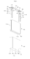
- FIG. 1 is a perspective view of a secondary battery according to an embodiment of the present invention
- FIG. 2 is a cross-sectional view of the secondary battery taken along the line I-I' of FIG. 1 ;
- FIG. 3 is an exploded perspective view of the secondary battery shown in FIG. 1 ;
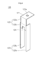
- FIG. 4 is a perspective view of a first current collector plate shown in FIG. 1 ;
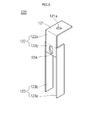
- FIG.5 is a perspective view of a first current collector plate of a secondary battery according to another embodiment of the present invention, corresponding to the first current collector plate shown in FIG. 4 ;
- FIG. 6A is a perspective view of a first current collector plate of a secondary battery according to still another embodiment of the present invention, corresponding to the first current collector plate shown in FIG. 4
- FIG. 6B is a cross-sectional view of the secondary battery taken along the line II-II' of FIG. 6A .
- FIG. 1 is a perspective view of a secondary battery according to an embodiment of the present invention
- FIG. 2 is a cross-sectional view of the secondary battery taken along the line I-I' of FIG. 1
- FIG. 3 is an exploded perspective view of the secondary battery shown in FIG. 1
- FIG. 4 is a perspective view of a first current collector plate shown in FIG. 1 .
- the secondary battery 100 includes electrode assemblies 110, a first current collector plate 120, a second current collector plate 130, a case 140 and a cap assembly 150.
- Each of the electrode assemblies 110 is formed by winding or laminating a stacked structure having a first electrode plate 111, a separator 113 and a second electrode plate 112, which are formed of a thin plate or layer.
- the first electrode plate 111 may function as a negative electrode and the second electrode plate 112 may function as a positive electrode, or vice versa.
- the first electrode plate 111 is formed by applying a first electrode active material, such as graphite or carbon, on a first electrode collector plate formed of metal foil, such as nickel or copper foil.
- the first electrode plate 111 includes a first electrode uncoated portion 111a on which the first electrode active metal is not applied.
- the first electrode uncoated portion 111a may function as a passage for current flowing between the first electrode plate 111 and the outside of the first electrode plate 111.
- the present invention does not limit the material of the first electrode plate 111 to those listed herein.
- the second electrode plate 112 is formed by applying a second electrode active material, such as a transition metal, on a second electrode collector plate formed of such as aluminum foil.
- the second electrode plate 112 includes a second electrode uncoated portion 112a on which the second electrode active metal is not applied.
- the second electrode uncoated portion 112a functions as a passage for current flowing between the second electrode plate 112 and the outside of the second electrode plate 112.
- the present invention does not limit the material of the second electrode plate 112 to those listed herein.
- the separator 113 is located between the first electrode plate 111 and the second electrode plate 112 to prevent short circuiting and allow the movement of lithium ions.
- the separator 113 may be formed of, for example, polyethylene, polypropylene, or combined film of polypropylene and polyethylene. However, the present invention does not limit the material of the separator 113 to those listed herein.
- the electrolyte may include an organic solvent such as ethylene carbonate (EC), propylene carbonate (PC), diethyl carbonate (DEC), ethyl methyl carbonate (EMC), or dimethyl carbonate (DMC), and a lithium salt such as LiPF 6 or LiBF 4 .
- the electrolyte may be a liquid, a solid, or a gel.
- a plurality of electrode assemblies 110 are accommodated in the case 140.
- two of the electrode assemblies 110 are accommodated in the case 140.
- One electrode assembly positioned ahead in the case 140 is referred to as a first electrode assembly 110a
- one electrode assembly positioned behind in the case 140 is referred to as a second electrode assembly 110b.
- the first current collector plate 120 may be formed of, for example, copper or a copper alloy, and contacts the first electrode uncoated portion 111a protruding from an end of the electrode assembly 110. In practice, the first current collector plate 120 is welded to the first electrode uncoated portion 111a to be electrically connected to the first electrode plate 111. Referring to FIG. 4 , the first current collector plate 120 includes a first horizontal part 121, a first vertical part 122, first extending parts 123 and a first resistance increasing unit 124.
- the first horizontal part 121 is installed between a top portion of the electrode assemblies 110 and a bottom portion of the cap assembly 150 in the form of a plate.
- the first horizontal part 121 is formed to be generally parallel to a cap plate 151 of the cap assembly 150.
- the first horizontal part 121 has a first terminal hole 121a formed therein.
- a first electrode terminal 152 of the cap assembly 150 may be fitted into and coupled to the first terminal hole 121a.
- the first vertical part 122 is bent and extends from an end of the first horizontal part 121.
- the first vertical part 122 is formed to be generally perpendicular to the first horizontal part 121 and the cap plate 151 and is formed to be generally parallel to a side surface 142 of the case 140.
- the first vertical part 122 is formed to be generally parallel to short side surfaces 142c and 142d of the case 140.
- the first vertical part 122 includes a first region 122a and a second region 122b.
- the first region 122a is a part connected to the first horizontal part 121
- the second region 122b is a region downwardly extending from the first region 122a.
- the first extending parts 123 are coupled to the second region 122b.
- the second region 122b serves to connect the first electrode assembly 110a to the second electrode assembly 110b.
- the first extending parts 123 are connected to the first electrode assembly 110a and the second electrode assembly 110b, and the second region 122b connects the first extending parts 123 to each other.
- the first resistance increasing unit 124 to be described below is formed in the second region 122a.
- the first extending parts 123 are positioned on both side surfaces of the first vertical part 122. In one embodiment, the first extending parts 123 are coupled to opposite sides of the second region 122b. In addition, the first extending parts 123 are coupled to the overall side surface of the second region 122b and are formed to extend from the second region 122b. In addition, the first extending parts 123 are formed to be parallel to the long side surfaces 142a and 142b of the case 140 and are coupled to the first electrode uncoated portions 111a of the electrode assemblies 110. Therefore, each of the first extending parts 123 may be formed to have lengths equal to or smaller than those of the first electrode uncoated portions 111a.
- the first extending parts 123 include a front surface extending part 123a and a rear surface extending part 123b.
- the front surface extending part 123a and the rear surface extending part 123b face and are opposite to each other.
- the front surface extending part 123a is coupled to the first electrode assembly 110a
- the rear surface extending part 123b is coupled to the second electrode assembly 110b.
- the first electrode uncoated portion 111a of the first electrode assembly 110a is welded to the front surface extending part 123a
- the first electrode uncoated portion 111a of the second electrode assembly 110b is welded to the rear surface extending part 123b.
- the first resistance increasing unit 124 is formed in the second region 122b of the first vertical part 122.
- the first resistance increasing unit 124 is formed in the second region 122b and is formed as an open hole having one side opened, i.e., a notch. Therefore, a longitudinal width of the second region 122b connecting the front surface extending part 123a and the rear surface extending part 123b is reduced by the first resistance increasing unit 124, and the resistance of the second region 122b increases.
- a movement path of current flowing from the front surface extending part 123a to the rear surface extending part 123b narrows by the first resistance increasing unit 124. In other words, when the first resistance increasing unit 124 is formed in the second region 122b, a bottleneck occurs in which the current flowing through the second region 122b concentrates in one direction, thereby increasing the resistance of the second region 122b.
- the first resistance increasing unit 124 is formed to have a longitudinal width smaller than a width of the second region 122b to allow the current to flow from the front surface extending part 123a to the rear surface extending part 123b.
- the first resistance increasing unit 124 may be formed in any shape so long as it can reduce the longitudinal width of the second region 122b.
- the first resistance increasing unit 124 may be formed of various shapes, such as a rectangle, a triangle, a circle, or an ellipse having one side opened.
- a nail penetration test is generally used as one of evaluation tests of secondary battery safety.
- a nail is allowed to penetrate in a direction in which the electrode assemblies are stacked to forcibly generate internal short-circuit, and the extent of heat generated is investigated, thereby evaluating the safety of the secondary battery. If the internal short-circuit is caused by the nail passing through the first electrode assembly, a large amount of short-circuit current is instantaneously generated. The short-circuit current flows in to the second electrode assembly through the second region, and abnormal heat generation and thermal runaway of the electrode assemblies may occur due to the internal short-circuit current.
- the secondary battery 100 according to the embodiment of the present invention since the first resistance increasing unit 124 is formed in the second region 122b connecting the first electrode assembly 110a to the second electrode assembly 110b, the resistance of the second region 122b is relatively large. Therefore, the magnitude of the short-circuit current passing the second region 122b can be reduced or controlled to be at a constant level. Accordingly, the secondary battery 100 according to the embodiment of the present invention may have improved safety by suppressing abnormal heat generation.
- the second current collector plate 130 is formed of a conductive material, for example, aluminum or an aluminum alloy, and contacts the second electrode uncoated portion 112a protruding from the other end of each of the electrode assemblies 110. In practice, the second current collector plate 130 is welded to the second electrode uncoated portion 112a to be electrically connected to the second electrode plate 112.
- the second current collector plate 130 includes a second horizontal part 131, a second vertical part 132, second extending parts 133 and a second resistance increasing unit 134.
- the second current collector plate 130 has substantially the same configuration as the first current collector plate 120 shown in FIG. 4 , and repeated explanations will be omitted.
- the case 140 is formed of a conductive metal, such as aluminum, an aluminum alloy or a nickel plated steel and has an approximately hexahedron shape provided with an opening through which the electrode assemblies 110, the first current collector plate 120 and the second current collector plate 130 are inserted and placed. Since the case 140 and the cap assembly 150 are illustrated in an assembled state in FIG. 2 , the opening of the case 140 is not shown. However, it will be appreciated that the opening corresponds to a substantially opened portion of the edge of the cap assembly 150.
- the case 140 includes a bottom surface 141 and side surfaces 142 upwardly extending from the bottom surface 141.
- the side surfaces 142 include a pair of long side surfaces 142a and 142b facing each other, and a pair of short side surfaces 142c and 142d connecting the long side surfaces 142a and 142b and facing each other.
- the inner surface of the case 140 may be treated to be insulated from the electrode assemblies 110, the first current collector plate 120, the second current collector plate 130 and the cap assembly 150.
- the case 140 may have a polarity and may serve as, for example, a positive electrode.
- the cap assembly 150 is coupled to the case 140.
- the cap assembly 150 includes the cap plate 151, the first electrode terminal 152, the second electrode terminal 153, a gasket 154, and a terminal plate 155.
- the cap assembly 150 further includes a plug 156, a vent plate 157, a connection member 158, an upper insulation member 159, and a lower insulation member 160.
- the cap plate 151 closes the opening of the case 140.
- the cap plate 151 may be formed of the same material the case 140.
- the cap plate 151 may be coupled to the case 140 by laser welding.
- the cap plate 151 and the case 140 may have the same polarity.
- the first electrode terminal 152 is electrically connected to the first current collector plate 120 while passing through one side of the cap plate 151.
- the first electrode terminal 152 is formed in a pillar shape.
- the first electrode terminal 152 upwardly protrudes and extends from the cap plate 151, and a flange 152a is formed at a lower portion of the cap plate 151 to prevent the first electrode terminal 152 from being dislodged from the cap plate 151.
- a region of the first electrode terminal 152 positioned under the flange 152a is fitted into the first terminal hole 121a of the first current collector plate 120.
- the first electrode terminal 152 is insulated from the cap plate 151.
- the second electrode terminal 153 is electrically connected to the second current collector plate 130 while passing through the other side of the cap plate 151. Since the second electrode terminal 153 has the same shape as the first electrode terminal 152, repeated explanations will be omitted. In one embodiment, the second electrode terminal 153 may be electrically connected to the cap plate 151.
- the gasket 154 is formed of an insulating material, and is located between the cap plate 151 and the first and second electrode terminals 152 and 153 to seal spaces between the cap plate 151 and the first and second electrode terminals 152 and 153.
- the gasket 154 prevents the introduction of moisture into the secondary battery 100 or the leakage of the electrolyte from the secondary battery 100.
- the terminal plate 155 is coupled to the first electrode terminal 152 and the second electrode terminal 153.
- the terminal plate 155 is welded to the first electrode terminal 152 and the second electrode terminal 153, thereby fixing the first electrode terminal 152 and the second electrode terminal 153 to the cap plate 151.
- boundary regions between each of the first electrode terminal 152 and the second electrode terminal 153, exposed to the upper portion of the cap plate 151, and the terminal plate 155, are welded to each other.
- laser beams are applied to the boundary regions between each of the upwardly exposed first and second electrode terminals 152 and 153 and the terminal plate 155, thereby welding the boundary regions to each other by fusing and cooling.
- the plug 156 closes an electrolyte injection hole 151a of the cap plate 151.
- the vent plate 157 is installed in a vent hole 151b of the cap plate 151 and has a notch 157a to be opened at a set pressure.
- connection member 158 is formed such that the second electrode terminal 153 is fitted into a region between the second electrode terminal 153 and the cap plate 151 and makes close contact with the cap plate 151 and the gasket 154 through the terminal plate 155.
- the connection member 158 is electrically connected to the second electrode terminal 153 and the cap plate 151.
- the upper insulation member 159 is formed such that the first electrode terminal 152 is fitted into a region between the first electrode terminal 152 and the cap plate 151 and makes close contact with the cap plate 151 and the gasket 154 through the terminal plate 155.
- the upper insulation member 159 insulates the first electrode terminal 152 and the cap plate 151 from each other.
- the lower insulation member 160 is formed between each of the first current collector plate 120 and the second current collector plate 130 and the cap plate 151, thereby preventing unnecessary short-circuits.
- the first resistance increasing unit 124 which increases the resistance of the first current collector plate 120 is formed in the second region 122b of the first current collector plate 120 connecting the first electrode assembly 110a and the second electrode assembly 110b, thereby reducing the magnitude of short-circuit current or controlling the same at a constant level during a nail penetration test. Accordingly, the secondary battery 100 according to the embodiment of the present invention may have improved safety by suppressing abnormal heat generation of the first and second electrode assemblies 110a and 110b.
- FIG. 5 is a perspective view of a first current collector plate of a secondary battery according to another embodiment of the present invention, corresponding to the first current collector plate shown in FIG. 4 .
- the first current collecting plate for a secondary battery shown in FIG. 5 is substantially the same first current collecting plate 120 shown in FIG. 4 in view of configurations and functions, except for a configuration of a first resistance increasing unit 224 of a first current collector plate 220.
- first resistance increasing unit 224 of the first current collector plate 220 is substantially the same.
- the first current collector plate 220 includes a first horizontal part 121, a first vertical part 122, first extending parts 123 and a first resistance increasing unit 224.
- the first resistance increasing unit 224 is formed in a second region 122b of the first vertical part 122.
- the first resistance increasing unit 224 formed in the second region 122b is formed as a throughhole passing through the center of the second region 122b.
- a longitudinal width of the second region 122b connecting a front surface extending part 123a and a rear surface extending part 123b is reduced by the throughhole and the resistance of the second region 122b increases.
- a movement path of current flowing from the front surface extending part 123a to the rear surface extending part 123b narrows by the throughhole.
- the first resistance increasing unit 224 is formed in the second region 122b in the form of a throughhole, a bottleneck occurs, in which the current flowing through the second region 122b concentrates in opposite directions of the throughhole, thereby increasing the resistance of the second region 122b.
- FIG. 6A is a perspective view of a first current collector plate of a secondary battery according to still another embodiment of the present invention, corresponding to the first current collector plate shown in FIG. 4
- FIG. 6B is a cross-sectional view of the secondary battery taken along the line II - II' of FIG. 6A .
- the first current collecting plate for a secondary battery shown in FIG. 6 is substantially the same first current collecting plate 120 shown in FIG. 4 in view of configurations and functions, except for a configuration of a first resistance increasing unit 324 of a first current collector plate 320.
- first resistance increasing unit 324 of the first current collector plate 320 is substantially the same.
- the first current collector plate 320 includes a first horizontal part 121, a first vertical part 122, first extending parts 123 and the first resistance increasing unit 324.
- the first resistance increasing unit 324 is formed in a second region 122b of the first vertical part 122.
- the first resistance increasing unit 324 connects a front surface extending part 123a to a rear surface extending part 123b and is formed in an uneven shape or a block-S pattern shape.
- the first resistance increasing unit 324 comprises a plurality of corrugations formed in the second region. Therefore, a horizontal width of the second region 122b connecting the front surface extending part 123a to the rear surface extending part 123b is effectively increased by the first resistance increasing unit 324.
- the uneven first resistance increasing unit 324 is formed in the second region 122b, the horizontal width of the second region 122b is effectively increased, and therefore the resistance of the second region 122b may also be increased.
- the first resistance increasing unit 324 may be formed in any shape so long as it can increase the horizontal width of the second region 122b.
Landscapes
- Chemical & Material Sciences (AREA)
- Chemical Kinetics & Catalysis (AREA)
- Electrochemistry (AREA)
- General Chemical & Material Sciences (AREA)
- Engineering & Computer Science (AREA)
- Manufacturing & Machinery (AREA)
- Connection Of Batteries Or Terminals (AREA)
- Secondary Cells (AREA)
Abstract
Description
- The present invention relates to a secondary battery.
- Unlike a primary battery which cannot be recharged, a secondary battery can be repeatedly charged and discharged. Low capacity batteries that use single battery cells are used as power sources for various portable small-sized electronic devices such as cellular phones, and camcorders. High power batteries that use tens of battery cells connected to each other in a battery pack are used as power sources for electric scooters, hybrid vehicles or electric vehicles.
- Secondary batteries may be classified into different types such as cylindrical and prismatic batteries. The secondary battery is generally configured by accommodating an electrode assembly having a positive plate and a negative plate and a separator as an insulator located therebetween in a case with an electrolyte and installing a cap plate having electrode terminals in the case.
- One of the evaluation tests of secondary battery safety is a nail penetration test. In the nail penetration test, a nail is allowed to penetrate in a direction in which the electrode assemblies are stacked to forcibly cause an internal short-circuit, and the extent of heat generated is investigated, thereby evaluating the safety of the secondary battery. In certain batteries, a large amount of short-circuit current is instantaneously generated due to the internal short-circuit, thereby resulting in abnormal heat generation and thermal runaway of the electrode assemblies. Accordingly, there is a demand for a secondary battery configured to improve safety of the secondary battery.
- Aspects of the present invention provide a secondary battery, which can reduce the magnitude of short-circuit current or controlling the same at a constant level during a nail penetration test by forming a resistance increasing unit increasing the resistance of a current collector plate, thereby improving safety by preventing ignition and explosion of an electrode assembly.
- In accordance with one aspect of the present invention, there is provided a secondary battery including a plurality of electrode assemblies, a current collector plate electrically connecting the plurality of electrode assemblies, a case accommodating the plurality of electrode assemblies, and a cap plate sealing the case, wherein the current collector plate has a resistance increasing unit formed therein to increase the resistance of the current collector plate.
- The current collector plate may include a horizontal part positioned between the cap plate and the electrode assemblies, a vertical part bent and extending from the horizontal part, and extending parts formed at opposite sides of the vertical part, extending to a lower portion of the case and electrically connected to the electrode assemblies.
- Each of the vertical part may include a first region extending from the horizontal part; and a second region extending from the first region and coupled to the extending parts.
- The resistance increasing unit may be formed in the second region.
- In addition, the resistance increasing unit may pass through the second region and may be formed as an open hole having one side opened.
- The open hole may have a smaller width than the second region.
- The resistance increasing unit may be formed as a throughhole passing through the second region.
- The throughhole may have a smaller width than the second region.
- The resistance increasing unit may be formed in an uneven shape to increase a width of the second region.
- The plurality of electrode assemblies may include a first electrode assembly and a second electrode assembly, and the extending parts may include a front surface extending part electrically connected to the first electrode assembly and a rear surface extending part electrically connected to the second electrode assembly.
- The second region may connect the front surface extending part to the rear surface extending part.
- The case may include a bottom surface, and a pair of long side surfaces and a pair of short side surfaces upwardly extending from the bottom surface, the vertical part may be parallel to the short side surfaces, and the extending parts may be parallel to the long side surfaces.
- The plurality of electrode assemblies may be stacked to be parallel to the long side surface.
- The secondary battery may further include an electrode terminal formed to pass through the cap plate. Here, the electrode terminal is electrically connected to the horizontal part.
- The horizontal part may have a terminal hole to which the electrode terminal is coupled.
- Each of the electrode assemblies may include a first electrode plate, a second electrode plate and a separator located between the first electrode plate and the second electrode plate, and the current collector plate may be electrically connected to a first uncoated portion of the first electrode plate or a second uncoated portion of the second electrode plate.
- As described above, in the secondary battery according to the embodiment of the present invention, the resistance increasing unit is formed in the second region of the current collector plate connecting the first electrode assembly to the second electrode assembly, thereby reducing the magnitude of short-circuit current passing the second region and controlling the same at a constant level. Accordingly, the secondary battery according to the embodiment of the present invention may improve its safety by preventing abnormal ignition or explosion of the electrode assemblies.
- Additional aspects and/or advantages of the invention will be set forth in part in the description which follows and, in part, will be obvious from the description, or may be learned by practice of the invention.
- The objects, features and advantages of the present invention will be more apparent from the following detailed description in conjunction with the accompanying drawings, in which:
-
FIG. 1 is a perspective view of a secondary battery according to an embodiment of the present invention; -
FIG. 2 is a cross-sectional view of the secondary battery taken along the line I-I' ofFIG. 1 ; -
FIG. 3 is an exploded perspective view of the secondary battery shown inFIG. 1 ; -
FIG. 4 is a perspective view of a first current collector plate shown inFIG. 1 ; -
FIG.5 is a perspective view of a first current collector plate of a secondary battery according to another embodiment of the present invention, corresponding to the first current collector plate shown inFIG. 4 ; and -
FIG. 6A is a perspective view of a first current collector plate of a secondary battery according to still another embodiment of the present invention, corresponding to the first current collector plate shown inFIG. 4 , andFIG. 6B is a cross-sectional view of the secondary battery taken along the line II-II' ofFIG. 6A . - Hereinafter, examples of embodiments of the invention will be described in detail with reference to the accompanying drawings such that they can easily be made and used by those skilled in the art.
-
FIG. 1 is a perspective view of a secondary battery according to an embodiment of the present invention,FIG. 2 is a cross-sectional view of the secondary battery taken along the line I-I' ofFIG. 1 ,FIG. 3 is an exploded perspective view of the secondary battery shown inFIG. 1 , andFIG. 4 is a perspective view of a first current collector plate shown inFIG. 1 . - Referring to
FIGS. 1 to 4 , thesecondary battery 100 according to an embodiment of the present invention includeselectrode assemblies 110, a firstcurrent collector plate 120, a secondcurrent collector plate 130, acase 140 and acap assembly 150. - Each of the
electrode assemblies 110 is formed by winding or laminating a stacked structure having afirst electrode plate 111, aseparator 113 and asecond electrode plate 112, which are formed of a thin plate or layer. Here, thefirst electrode plate 111 may function as a negative electrode and thesecond electrode plate 112 may function as a positive electrode, or vice versa. - The
first electrode plate 111 is formed by applying a first electrode active material, such as graphite or carbon, on a first electrode collector plate formed of metal foil, such as nickel or copper foil. Thefirst electrode plate 111 includes a first electrode uncoatedportion 111a on which the first electrode active metal is not applied. The first electrodeuncoated portion 111a may function as a passage for current flowing between thefirst electrode plate 111 and the outside of thefirst electrode plate 111. However, the present invention does not limit the material of thefirst electrode plate 111 to those listed herein. - The
second electrode plate 112 is formed by applying a second electrode active material, such as a transition metal, on a second electrode collector plate formed of such as aluminum foil. Thesecond electrode plate 112 includes a second electrode uncoatedportion 112a on which the second electrode active metal is not applied. The second electrode uncoatedportion 112a functions as a passage for current flowing between thesecond electrode plate 112 and the outside of thesecond electrode plate 112. However, the present invention does not limit the material of thesecond electrode plate 112 to those listed herein. - The
separator 113 is located between thefirst electrode plate 111 and thesecond electrode plate 112 to prevent short circuiting and allow the movement of lithium ions. Theseparator 113 may be formed of, for example, polyethylene, polypropylene, or combined film of polypropylene and polyethylene. However, the present invention does not limit the material of theseparator 113 to those listed herein. - Each of the electrode assemblies 110 and an electrolyte are accommodated within the
case 140. The electrolyte may include an organic solvent such as ethylene carbonate (EC), propylene carbonate (PC), diethyl carbonate (DEC), ethyl methyl carbonate (EMC), or dimethyl carbonate (DMC), and a lithium salt such as LiPF6 or LiBF4. The electrolyte may be a liquid, a solid, or a gel. - In addition, a plurality of
electrode assemblies 110 are accommodated in thecase 140. In one embodiment, as shown inFIG. 3 , two of theelectrode assemblies 110 are accommodated in thecase 140. One electrode assembly positioned ahead in thecase 140 is referred to as afirst electrode assembly 110a, and one electrode assembly positioned behind in thecase 140 is referred to as asecond electrode assembly 110b. - The first
current collector plate 120 may be formed of, for example, copper or a copper alloy, and contacts the first electrodeuncoated portion 111a protruding from an end of theelectrode assembly 110. In practice, the firstcurrent collector plate 120 is welded to the first electrodeuncoated portion 111a to be electrically connected to thefirst electrode plate 111. Referring toFIG. 4 , the firstcurrent collector plate 120 includes a firsthorizontal part 121, a firstvertical part 122, first extendingparts 123 and a firstresistance increasing unit 124. - The first
horizontal part 121 is installed between a top portion of theelectrode assemblies 110 and a bottom portion of thecap assembly 150 in the form of a plate. In detail, the firsthorizontal part 121 is formed to be generally parallel to acap plate 151 of thecap assembly 150. In addition, the firsthorizontal part 121 has a firstterminal hole 121a formed therein. Afirst electrode terminal 152 of thecap assembly 150 may be fitted into and coupled to the firstterminal hole 121a. - The first
vertical part 122 is bent and extends from an end of the firsthorizontal part 121. The firstvertical part 122 is formed to be generally perpendicular to the firsthorizontal part 121 and thecap plate 151 and is formed to be generally parallel to aside surface 142 of thecase 140. In particular, the firstvertical part 122 is formed to be generally parallel to short side surfaces 142c and 142d of thecase 140. - The first
vertical part 122 includes afirst region 122a and asecond region 122b. Thefirst region 122a is a part connected to the firsthorizontal part 121, and thesecond region 122b is a region downwardly extending from thefirst region 122a. In addition, the first extendingparts 123 are coupled to thesecond region 122b. In practice, thesecond region 122b serves to connect thefirst electrode assembly 110a to thesecond electrode assembly 110b. In other words, the first extendingparts 123 are connected to thefirst electrode assembly 110a and thesecond electrode assembly 110b, and thesecond region 122b connects the first extendingparts 123 to each other. In addition, the firstresistance increasing unit 124 to be described below is formed in thesecond region 122a. - The first extending
parts 123 are positioned on both side surfaces of the firstvertical part 122. In one embodiment, the first extendingparts 123 are coupled to opposite sides of thesecond region 122b. In addition, the first extendingparts 123 are coupled to the overall side surface of thesecond region 122b and are formed to extend from thesecond region 122b. In addition, the first extendingparts 123 are formed to be parallel to thelong side surfaces case 140 and are coupled to the first electrodeuncoated portions 111a of theelectrode assemblies 110. Therefore, each of the first extendingparts 123 may be formed to have lengths equal to or smaller than those of the first electrodeuncoated portions 111a. - The first extending
parts 123 include a frontsurface extending part 123a and a rearsurface extending part 123b. The frontsurface extending part 123a and the rearsurface extending part 123b face and are opposite to each other. The frontsurface extending part 123a is coupled to thefirst electrode assembly 110a, and the rearsurface extending part 123b is coupled to thesecond electrode assembly 110b. In detail, the first electrodeuncoated portion 111a of thefirst electrode assembly 110a is welded to the frontsurface extending part 123a, and the first electrodeuncoated portion 111a of thesecond electrode assembly 110b is welded to the rearsurface extending part 123b. - The first
resistance increasing unit 124 is formed in thesecond region 122b of the firstvertical part 122. In addition, the firstresistance increasing unit 124 is formed in thesecond region 122b and is formed as an open hole having one side opened, i.e., a notch. Therefore, a longitudinal width of thesecond region 122b connecting the frontsurface extending part 123a and the rearsurface extending part 123b is reduced by the firstresistance increasing unit 124, and the resistance of thesecond region 122b increases. In addition, a movement path of current flowing from the frontsurface extending part 123a to the rearsurface extending part 123b narrows by the firstresistance increasing unit 124. In other words, when the firstresistance increasing unit 124 is formed in thesecond region 122b, a bottleneck occurs in which the current flowing through thesecond region 122b concentrates in one direction, thereby increasing the resistance of thesecond region 122b. - The first
resistance increasing unit 124 is formed to have a longitudinal width smaller than a width of thesecond region 122b to allow the current to flow from the frontsurface extending part 123a to the rearsurface extending part 123b. In addition, the firstresistance increasing unit 124 may be formed in any shape so long as it can reduce the longitudinal width of thesecond region 122b. For example, the firstresistance increasing unit 124 may be formed of various shapes, such as a rectangle, a triangle, a circle, or an ellipse having one side opened. - A nail penetration test is generally used as one of evaluation tests of secondary battery safety. In the nail penetration test, a nail is allowed to penetrate in a direction in which the electrode assemblies are stacked to forcibly generate internal short-circuit, and the extent of heat generated is investigated, thereby evaluating the safety of the secondary battery. If the internal short-circuit is caused by the nail passing through the first electrode assembly, a large amount of short-circuit current is instantaneously generated. The short-circuit current flows in to the second electrode assembly through the second region, and abnormal heat generation and thermal runaway of the electrode assemblies may occur due to the internal short-circuit current.
- However, in the
secondary battery 100 according to the embodiment of the present invention, since the firstresistance increasing unit 124 is formed in thesecond region 122b connecting thefirst electrode assembly 110a to thesecond electrode assembly 110b, the resistance of thesecond region 122b is relatively large. Therefore, the magnitude of the short-circuit current passing thesecond region 122b can be reduced or controlled to be at a constant level. Accordingly, thesecondary battery 100 according to the embodiment of the present invention may have improved safety by suppressing abnormal heat generation. - The second
current collector plate 130 is formed of a conductive material, for example, aluminum or an aluminum alloy, and contacts the second electrodeuncoated portion 112a protruding from the other end of each of theelectrode assemblies 110. In practice, the secondcurrent collector plate 130 is welded to the second electrodeuncoated portion 112a to be electrically connected to thesecond electrode plate 112. The secondcurrent collector plate 130 includes a secondhorizontal part 131, a secondvertical part 132, second extendingparts 133 and a secondresistance increasing unit 134. - The second
current collector plate 130 has substantially the same configuration as the firstcurrent collector plate 120 shown inFIG. 4 , and repeated explanations will be omitted. - The
case 140 is formed of a conductive metal, such as aluminum, an aluminum alloy or a nickel plated steel and has an approximately hexahedron shape provided with an opening through which theelectrode assemblies 110, the firstcurrent collector plate 120 and the secondcurrent collector plate 130 are inserted and placed. Since thecase 140 and thecap assembly 150 are illustrated in an assembled state inFIG. 2 , the opening of thecase 140 is not shown. However, it will be appreciated that the opening corresponds to a substantially opened portion of the edge of thecap assembly 150. In addition, thecase 140 includes abottom surface 141 andside surfaces 142 upwardly extending from thebottom surface 141. The side surfaces 142 include a pair oflong side surfaces long side surfaces case 140 may be treated to be insulated from theelectrode assemblies 110, the firstcurrent collector plate 120, the secondcurrent collector plate 130 and thecap assembly 150. In one embodiment, thecase 140 may have a polarity and may serve as, for example, a positive electrode. - The
cap assembly 150 is coupled to thecase 140. In one embodiment, thecap assembly 150 includes thecap plate 151, thefirst electrode terminal 152, thesecond electrode terminal 153, agasket 154, and aterminal plate 155. In addition, thecap assembly 150 further includes aplug 156, avent plate 157, aconnection member 158, anupper insulation member 159, and alower insulation member 160. - The
cap plate 151 closes the opening of thecase 140. Thecap plate 151 may be formed of the same material thecase 140. For example, thecap plate 151 may be coupled to thecase 140 by laser welding. In one embodiment, thecap plate 151 and thecase 140 may have the same polarity. - The
first electrode terminal 152 is electrically connected to the firstcurrent collector plate 120 while passing through one side of thecap plate 151. Thefirst electrode terminal 152 is formed in a pillar shape. In addition, thefirst electrode terminal 152 upwardly protrudes and extends from thecap plate 151, and aflange 152a is formed at a lower portion of thecap plate 151 to prevent thefirst electrode terminal 152 from being dislodged from thecap plate 151. A region of thefirst electrode terminal 152 positioned under theflange 152a is fitted into the firstterminal hole 121a of the firstcurrent collector plate 120. In one embodiment, thefirst electrode terminal 152 is insulated from thecap plate 151. - The
second electrode terminal 153 is electrically connected to the secondcurrent collector plate 130 while passing through the other side of thecap plate 151. Since thesecond electrode terminal 153 has the same shape as thefirst electrode terminal 152, repeated explanations will be omitted. In one embodiment, thesecond electrode terminal 153 may be electrically connected to thecap plate 151. - The
gasket 154 is formed of an insulating material, and is located between thecap plate 151 and the first andsecond electrode terminals cap plate 151 and the first andsecond electrode terminals gasket 154 prevents the introduction of moisture into thesecondary battery 100 or the leakage of the electrolyte from thesecondary battery 100. - The
terminal plate 155 is coupled to thefirst electrode terminal 152 and thesecond electrode terminal 153. In addition, theterminal plate 155 is welded to thefirst electrode terminal 152 and thesecond electrode terminal 153, thereby fixing thefirst electrode terminal 152 and thesecond electrode terminal 153 to thecap plate 151. In other words, boundary regions between each of thefirst electrode terminal 152 and thesecond electrode terminal 153, exposed to the upper portion of thecap plate 151, and theterminal plate 155, are welded to each other. For example, laser beams are applied to the boundary regions between each of the upwardly exposed first andsecond electrode terminals terminal plate 155, thereby welding the boundary regions to each other by fusing and cooling. - The
plug 156 closes anelectrolyte injection hole 151a of thecap plate 151. Thevent plate 157 is installed in avent hole 151b of thecap plate 151 and has anotch 157a to be opened at a set pressure. - The
connection member 158 is formed such that thesecond electrode terminal 153 is fitted into a region between thesecond electrode terminal 153 and thecap plate 151 and makes close contact with thecap plate 151 and thegasket 154 through theterminal plate 155. Theconnection member 158 is electrically connected to thesecond electrode terminal 153 and thecap plate 151. - The
upper insulation member 159 is formed such that thefirst electrode terminal 152 is fitted into a region between thefirst electrode terminal 152 and thecap plate 151 and makes close contact with thecap plate 151 and thegasket 154 through theterminal plate 155. Theupper insulation member 159 insulates thefirst electrode terminal 152 and thecap plate 151 from each other. - The
lower insulation member 160 is formed between each of the firstcurrent collector plate 120 and the secondcurrent collector plate 130 and thecap plate 151, thereby preventing unnecessary short-circuits. - As described above, in the
secondary battery 100 according to the embodiment of the present invention, the firstresistance increasing unit 124 which increases the resistance of the firstcurrent collector plate 120 is formed in thesecond region 122b of the firstcurrent collector plate 120 connecting thefirst electrode assembly 110a and thesecond electrode assembly 110b, thereby reducing the magnitude of short-circuit current or controlling the same at a constant level during a nail penetration test. Accordingly, thesecondary battery 100 according to the embodiment of the present invention may have improved safety by suppressing abnormal heat generation of the first andsecond electrode assemblies -
FIG. 5 is a perspective view of a first current collector plate of a secondary battery according to another embodiment of the present invention, corresponding to the first current collector plate shown inFIG. 4 . - The first current collecting plate for a secondary battery shown in
FIG. 5 is substantially the same firstcurrent collecting plate 120 shown inFIG. 4 in view of configurations and functions, except for a configuration of a firstresistance increasing unit 224 of a firstcurrent collector plate 220. Thus, repeated illustration and explanations of the same functional components will be omitted, and the following description will focus on the firstresistance increasing unit 224 of the firstcurrent collector plate 220. - Referring to
FIG. 5 , the firstcurrent collector plate 220 includes a firsthorizontal part 121, a firstvertical part 122, first extendingparts 123 and a firstresistance increasing unit 224. - The first
resistance increasing unit 224 is formed in asecond region 122b of the firstvertical part 122. In addition, the firstresistance increasing unit 224 formed in thesecond region 122b is formed as a throughhole passing through the center of thesecond region 122b. Thus, a longitudinal width of thesecond region 122b connecting a frontsurface extending part 123a and a rearsurface extending part 123b is reduced by the throughhole and the resistance of thesecond region 122b increases. In addition, a movement path of current flowing from the frontsurface extending part 123a to the rearsurface extending part 123b narrows by the throughhole. In other words, if the firstresistance increasing unit 224 is formed in thesecond region 122b in the form of a throughhole, a bottleneck occurs, in which the current flowing through thesecond region 122b concentrates in opposite directions of the throughhole, thereby increasing the resistance of thesecond region 122b. -
FIG. 6A is a perspective view of a first current collector plate of a secondary battery according to still another embodiment of the present invention, corresponding to the first current collector plate shown inFIG. 4 , andFIG. 6B is a cross-sectional view of the secondary battery taken along the line II - II' ofFIG. 6A . - The first current collecting plate for a secondary battery shown in
FIG. 6 is substantially the same firstcurrent collecting plate 120 shown inFIG. 4 in view of configurations and functions, except for a configuration of a firstresistance increasing unit 324 of a firstcurrent collector plate 320. Thus, repeated illustration and explanations of the same functional components will be omitted, and the following description will focus on the firstresistance increasing unit 324 of the firstcurrent collector plate 320. - Referring to
FIGS. 6A and 6B , the firstcurrent collector plate 320 includes a firsthorizontal part 121, a firstvertical part 122, first extendingparts 123 and the firstresistance increasing unit 324. - The first
resistance increasing unit 324 is formed in asecond region 122b of the firstvertical part 122. In addition, the firstresistance increasing unit 324 connects a frontsurface extending part 123a to a rearsurface extending part 123b and is formed in an uneven shape or a block-S pattern shape. In other words, the firstresistance increasing unit 324 comprises a plurality of corrugations formed in the second region. Therefore, a horizontal width of thesecond region 122b connecting the frontsurface extending part 123a to the rearsurface extending part 123b is effectively increased by the firstresistance increasing unit 324. In other words, since the uneven firstresistance increasing unit 324 is formed in thesecond region 122b, the horizontal width of thesecond region 122b is effectively increased, and therefore the resistance of thesecond region 122b may also be increased. As described above, if the horizontal width of thesecond region 122b is increased by the firstresistance increasing unit 324, it is relatively difficult for the current to pass thesecond region 122b. Accordingly, the magnitude of short-circuit current passing thesecond region 122b can be reduced or controlled to be at a constant level. In addition, the firstresistance increasing unit 324 may be formed in any shape so long as it can increase the horizontal width of thesecond region 122b. - Although the secondary battery according to embodiments of the present invention have been described in detail hereinabove, it should be understood that many variations and modifications of the basic inventive concept herein described, which may appear to those skilled in the art, will still fall within the scope of the exemplary embodiments of the present invention as defined by the appended claims.
Claims (15)
- A secondary battery (100) comprising:a plurality of electrode assemblies (110);a current collector plate (120) electrically connecting the plurality of electrode assemblies together;a case (140) accommodating the plurality of electrode assemblies; anda cap plate (151) sealing the case, wherein the current collector plate (120) has a resistance increasing unit (124) thereon to increase the resistance of the current collector plate.
- The secondary battery of claim 1, wherein the current collector plate includes:a horizontal part (121) located between the cap plate and the electrode assemblies;a vertical part (122) bent and extending from the horizontal part; andextending parts (123) formed at opposing sides of the vertical part, extending to a lower portion of the case (140), and electrically connected to the electrode assemblies (110).
- The secondary battery of claim 2, wherein the vertical part includes:a first region (122a) extending from the horizontal part (121); anda second region (122b) extending from the first region (122a) and coupled to the extending parts.
- The secondary battery of claim 3, wherein the resistance increasing unit (124) is on the second region (122b).
- The secondary battery of claim 3 or 4, wherein the resistance increasing unit (124) passes through the second region and is a notch.
- The secondary battery of claim 5, wherein the notch has a smaller width than a width of the second region.
- The secondary battery of claim 3 or 4, wherein the resistance increasing unit (224) is formed as a throughhole passing through the second region.
- The secondary battery of claim 7, wherein the throughhole (224) has a smaller width than a width of the second region.
- The secondary battery of claim 3, wherein the resistance increasing unit (324) is formed in an uneven shape to effectively increase a width of the second region.
- The secondary battery of any one of claims 3 to 9, wherein the plurality of electrode assemblies comprise a first electrode assembly (110a) and a second electrode assembly (110b), and the extending parts (123) include a front surface extending part (123a) electrically connected to the first electrode assembly and a rear surface extending part (123b) electrically connected to the second electrode assembly.
- The secondary battery of claim 10, wherein the second region (122b) connects the front surface extending part (123a) to the rear surface extending part (123b).
- The secondary battery of any one of claims 2 to 11, wherein the case includes a bottom surface (141), a pair of long side surfaces (142a, 142b), and a pair of short side surfaces (142c, 142d) upwardly extending from the bottom surface, wherein the vertical part (122) is substantially parallel to the short side surfaces, and wherein the extending parts (123) are substantially parallel to the long side surfaces.
- The secondary battery of claim 12, wherein the plurality of electrode assemblies (110) are stacked to be substantially parallel to the long side surfaces (142a, 142b).
- The secondary battery of any one of claims 2 to 13, further comprising an electrode terminal (152) passing through the cap plate (151), wherein the electrode terminal is electrically connected to the horizontal part (121), and
wherein the horizontal part (121) has a terminal hole (121a) to which the electrode terminal (152) is coupled. - The secondary battery of any one of the preceding claims, wherein each of the electrode assemblies (110) includes a first electrode plate (111), a second electrode plate (112), and a separator (113) located between the first electrode plate and the second electrode plate, and wherein the current collector plate (120) is electrically connected to a first uncoated portion (111a) of the first electrode plate or a second uncoated portion (112a) of the second electrode plate.
Applications Claiming Priority (1)
| Application Number | Priority Date | Filing Date | Title |
|---|---|---|---|
| KR1020130043205A KR101675621B1 (en) | 2013-04-18 | 2013-04-18 | Secondary battery |
Publications (3)
| Publication Number | Publication Date |
|---|---|
| EP2793292A2 true EP2793292A2 (en) | 2014-10-22 |
| EP2793292A3 EP2793292A3 (en) | 2014-11-05 |
| EP2793292B1 EP2793292B1 (en) | 2020-05-20 |
Family
ID=49274549
Family Applications (1)
| Application Number | Title | Priority Date | Filing Date |
|---|---|---|---|
| EP13187261.6A Active EP2793292B1 (en) | 2013-04-18 | 2013-10-03 | Secondary battery |
Country Status (3)
| Country | Link |
|---|---|
| US (1) | US20140315073A1 (en) |
| EP (1) | EP2793292B1 (en) |
| KR (1) | KR101675621B1 (en) |
Cited By (4)
| Publication number | Priority date | Publication date | Assignee | Title |
|---|---|---|---|---|
| CN108199072A (en) * | 2018-01-16 | 2018-06-22 | 宁德时代新能源科技股份有限公司 | Rechargeable battery |
| CN109428046A (en) * | 2017-08-31 | 2019-03-05 | 三星Sdi株式会社 | Secondary cell |
| EP3716386A1 (en) * | 2019-03-29 | 2020-09-30 | Samsung SDI Co., Ltd. | Secondary battery |
| US11258140B2 (en) | 2017-08-31 | 2022-02-22 | Samsung Sdi Co., Ltd. | Secondary battery |
Families Citing this family (7)
| Publication number | Priority date | Publication date | Assignee | Title |
|---|---|---|---|---|
| KR102571487B1 (en) | 2017-08-31 | 2023-08-28 | 삼성에스디아이 주식회사 | Secondary Battery And Assembling Method thereof |
| KR102282482B1 (en) | 2018-02-06 | 2021-07-26 | 주식회사 엘지에너지솔루션 | Battery module and battery pack including the same |
| CN111384335B (en) | 2018-12-30 | 2024-09-13 | 宁德时代新能源科技股份有限公司 | Battery pack and vehicle |
| CN111384336B (en) * | 2018-12-30 | 2024-10-18 | 宁德时代新能源科技股份有限公司 | Battery module, battery pack and vehicle |
| CN111864172B (en) * | 2019-04-25 | 2025-01-17 | 宁德时代新能源科技股份有限公司 | Battery unit and battery module |
| KR20250086078A (en) * | 2023-12-06 | 2025-06-13 | 삼성에스디아이 주식회사 | secondary battery |
| SE2430477A1 (en) * | 2024-09-19 | 2025-12-23 | Northvolt Ab | A current collector |
Family Cites Families (9)
| Publication number | Priority date | Publication date | Assignee | Title |
|---|---|---|---|---|
| JP2003187856A (en) * | 2001-12-18 | 2003-07-04 | Japan Storage Battery Co Ltd | Battery |
| US9023513B2 (en) * | 2009-08-27 | 2015-05-05 | Samsung Sdi Co., Ltd. | Rechargeable secondary battery having improved safety against puncture and collapse |
| US8232000B2 (en) * | 2010-01-12 | 2012-07-31 | Sb Limotive Co., Ltd. | Rechargeable battery with terminal junction and prong |
| US8632911B2 (en) * | 2010-01-15 | 2014-01-21 | Samsung Sdi Co., Ltd. | Rechargeable battery |
| JP2011192518A (en) | 2010-03-15 | 2011-09-29 | Honda Motor Co Ltd | Secondary battery |
| KR101147176B1 (en) * | 2010-08-31 | 2012-05-25 | 에스비리모티브 주식회사 | Rechargeable battery |
| KR101222247B1 (en) * | 2010-12-24 | 2013-01-16 | 로베르트 보쉬 게엠베하 | Secondary battery |
| KR101243500B1 (en) * | 2011-03-04 | 2013-03-13 | 로베르트 보쉬 게엠베하 | Secondary battery improved swelling and penetration characteristic |
| KR101254871B1 (en) * | 2011-04-18 | 2013-04-15 | 로베르트 보쉬 게엠베하 | Secondary battery |
-
2013
- 2013-04-18 KR KR1020130043205A patent/KR101675621B1/en active Active
- 2013-08-02 US US13/958,488 patent/US20140315073A1/en not_active Abandoned
- 2013-10-03 EP EP13187261.6A patent/EP2793292B1/en active Active
Non-Patent Citations (1)
| Title |
|---|
| None |
Cited By (10)
| Publication number | Priority date | Publication date | Assignee | Title |
|---|---|---|---|---|
| CN109428046A (en) * | 2017-08-31 | 2019-03-05 | 三星Sdi株式会社 | Secondary cell |
| EP3451415A1 (en) * | 2017-08-31 | 2019-03-06 | Samsung SDI Co., Ltd. | Secondary battery |
| CN109428046B (en) * | 2017-08-31 | 2021-10-26 | 三星Sdi株式会社 | Secondary battery |
| US11258140B2 (en) | 2017-08-31 | 2022-02-22 | Samsung Sdi Co., Ltd. | Secondary battery |
| CN108199072A (en) * | 2018-01-16 | 2018-06-22 | 宁德时代新能源科技股份有限公司 | Rechargeable battery |
| US10826047B2 (en) | 2018-01-16 | 2020-11-03 | Contemporary Amperex Technology Co., Limited | Rechargeable battery |
| US11929521B2 (en) | 2018-01-16 | 2024-03-12 | Contemporary Amperex Technology Co., Limited | Rechargeable battery |
| EP3716386A1 (en) * | 2019-03-29 | 2020-09-30 | Samsung SDI Co., Ltd. | Secondary battery |
| CN111755731A (en) * | 2019-03-29 | 2020-10-09 | 三星Sdi株式会社 | Secondary battery |
| US11276876B2 (en) | 2019-03-29 | 2022-03-15 | Samsung Sdi Co., Ltd. | Secondary battery |
Also Published As
| Publication number | Publication date |
|---|---|
| EP2793292A3 (en) | 2014-11-05 |
| KR20140125256A (en) | 2014-10-28 |
| KR101675621B1 (en) | 2016-11-11 |
| US20140315073A1 (en) | 2014-10-23 |
| EP2793292B1 (en) | 2020-05-20 |
Similar Documents
| Publication | Publication Date | Title |
|---|---|---|
| EP2793292B1 (en) | Secondary battery | |
| US10826048B2 (en) | Secondary battery | |
| US10673055B2 (en) | Secondary battery | |
| US8828571B2 (en) | Secondary battery | |
| US9530999B2 (en) | Secondary battery module | |
| CN103943809B (en) | Secondary cell | |
| US8728644B2 (en) | Rechargeable battery | |
| US9490470B2 (en) | Secondary battery | |
| US10998534B2 (en) | Secondary battery | |
| US9570780B2 (en) | Rechargeable battery | |
| KR102165332B1 (en) | Secondary battery | |
| KR20190106073A (en) | Rechargeable battery | |
| US9166208B2 (en) | Rechargeable battery | |
| US9312531B2 (en) | Secondary battery | |
| US10211446B2 (en) | Rechargeable battery | |
| US9583752B2 (en) | Secondary battery | |
| KR101233535B1 (en) | Secondary battery | |
| KR102119049B1 (en) | Rechargeable battery having insulation case | |
| KR20120082182A (en) | Secondary battery | |
| US10333130B2 (en) | Secondary battery and secondary battery module | |
| KR102457497B1 (en) | Secondary battery |
Legal Events
| Date | Code | Title | Description |
|---|---|---|---|
| PUAL | Search report despatched |
Free format text: ORIGINAL CODE: 0009013 |
|
| PUAI | Public reference made under article 153(3) epc to a published international application that has entered the european phase |
Free format text: ORIGINAL CODE: 0009012 |
|
| 17P | Request for examination filed |
Effective date: 20131003 |
|
| AK | Designated contracting states |
Kind code of ref document: A2 Designated state(s): AL AT BE BG CH CY CZ DE DK EE ES FI FR GB GR HR HU IE IS IT LI LT LU LV MC MK MT NL NO PL PT RO RS SE SI SK SM TR |
|
| AX | Request for extension of the european patent |
Extension state: BA ME |
|
| AK | Designated contracting states |
Kind code of ref document: A3 Designated state(s): AL AT BE BG CH CY CZ DE DK EE ES FI FR GB GR HR HU IE IS IT LI LT LU LV MC MK MT NL NO PL PT RO RS SE SI SK SM TR |
|
| AX | Request for extension of the european patent |
Extension state: BA ME |
|
| RIC1 | Information provided on ipc code assigned before grant |
Ipc: H01M 2/26 20060101AFI20141002BHEP Ipc: H01M 2/34 20060101ALI20141002BHEP |
|
| R17P | Request for examination filed (corrected) |
Effective date: 20150402 |
|
| RBV | Designated contracting states (corrected) |
Designated state(s): AL AT BE BG CH CY CZ DE DK EE ES FI FR GB GR HR HU IE IS IT LI LT LU LV MC MK MT NL NO PL PT RO RS SE SI SK SM TR |
|
| 17Q | First examination report despatched |
Effective date: 20160316 |
|
| GRAP | Despatch of communication of intention to grant a patent |
Free format text: ORIGINAL CODE: EPIDOSNIGR1 |
|
| STAA | Information on the status of an ep patent application or granted ep patent |
Free format text: STATUS: GRANT OF PATENT IS INTENDED |
|
| GRAJ | Information related to disapproval of communication of intention to grant by the applicant or resumption of examination proceedings by the epo deleted |
Free format text: ORIGINAL CODE: EPIDOSDIGR1 |
|
| GRAC | Information related to communication of intention to grant a patent modified |
Free format text: ORIGINAL CODE: EPIDOSCIGR1 |
|
| GRAJ | Information related to disapproval of communication of intention to grant by the applicant or resumption of examination proceedings by the epo deleted |
Free format text: ORIGINAL CODE: EPIDOSDIGR1 |
|
| GRAP | Despatch of communication of intention to grant a patent |
Free format text: ORIGINAL CODE: EPIDOSNIGR1 |
|
| STAA | Information on the status of an ep patent application or granted ep patent |
Free format text: STATUS: EXAMINATION IS IN PROGRESS |
|
| GRAP | Despatch of communication of intention to grant a patent |
Free format text: ORIGINAL CODE: EPIDOSNIGR1 |
|
| STAA | Information on the status of an ep patent application or granted ep patent |
Free format text: STATUS: GRANT OF PATENT IS INTENDED |
|
| INTG | Intention to grant announced |
Effective date: 20191129 |
|
| INTG | Intention to grant announced |
Effective date: 20191213 |
|
| INTG | Intention to grant announced |
Effective date: 20191218 |
|
| GRAS | Grant fee paid |
Free format text: ORIGINAL CODE: EPIDOSNIGR3 |
|
| GRAA | (expected) grant |
Free format text: ORIGINAL CODE: 0009210 |
|
| STAA | Information on the status of an ep patent application or granted ep patent |
Free format text: STATUS: THE PATENT HAS BEEN GRANTED |
|
| AK | Designated contracting states |
Kind code of ref document: B1 Designated state(s): AL AT BE BG CH CY CZ DE DK EE ES FI FR GB GR HR HU IE IS IT LI LT LU LV MC MK MT NL NO PL PT RO RS SE SI SK SM TR |
|
| REG | Reference to a national code |
Ref country code: GB Ref legal event code: FG4D |
|
| REG | Reference to a national code |
Ref country code: CH Ref legal event code: EP |
|
| REG | Reference to a national code |
Ref country code: DE Ref legal event code: R096 Ref document number: 602013069227 Country of ref document: DE |
|
| REG | Reference to a national code |
Ref country code: AT Ref legal event code: REF Ref document number: 1273212 Country of ref document: AT Kind code of ref document: T Effective date: 20200615 |
|
| REG | Reference to a national code |
Ref country code: LT Ref legal event code: MG4D |
|
| REG | Reference to a national code |
Ref country code: NL Ref legal event code: MP Effective date: 20200520 |
|
| PG25 | Lapsed in a contracting state [announced via postgrant information from national office to epo] |
Ref country code: IS Free format text: LAPSE BECAUSE OF FAILURE TO SUBMIT A TRANSLATION OF THE DESCRIPTION OR TO PAY THE FEE WITHIN THE PRESCRIBED TIME-LIMIT Effective date: 20200920 Ref country code: PT Free format text: LAPSE BECAUSE OF FAILURE TO SUBMIT A TRANSLATION OF THE DESCRIPTION OR TO PAY THE FEE WITHIN THE PRESCRIBED TIME-LIMIT Effective date: 20200921 Ref country code: SE Free format text: LAPSE BECAUSE OF FAILURE TO SUBMIT A TRANSLATION OF THE DESCRIPTION OR TO PAY THE FEE WITHIN THE PRESCRIBED TIME-LIMIT Effective date: 20200520 Ref country code: LT Free format text: LAPSE BECAUSE OF FAILURE TO SUBMIT A TRANSLATION OF THE DESCRIPTION OR TO PAY THE FEE WITHIN THE PRESCRIBED TIME-LIMIT Effective date: 20200520 Ref country code: FI Free format text: LAPSE BECAUSE OF FAILURE TO SUBMIT A TRANSLATION OF THE DESCRIPTION OR TO PAY THE FEE WITHIN THE PRESCRIBED TIME-LIMIT Effective date: 20200520 Ref country code: GR Free format text: LAPSE BECAUSE OF FAILURE TO SUBMIT A TRANSLATION OF THE DESCRIPTION OR TO PAY THE FEE WITHIN THE PRESCRIBED TIME-LIMIT Effective date: 20200821 Ref country code: NO Free format text: LAPSE BECAUSE OF FAILURE TO SUBMIT A TRANSLATION OF THE DESCRIPTION OR TO PAY THE FEE WITHIN THE PRESCRIBED TIME-LIMIT Effective date: 20200820 |
|
| REG | Reference to a national code |
Ref country code: DE Ref legal event code: R079 Ref document number: 602013069227 Country of ref document: DE Free format text: PREVIOUS MAIN CLASS: H01M0002260000 Ipc: H01M0050531000 |
|
| PG25 | Lapsed in a contracting state [announced via postgrant information from national office to epo] |
Ref country code: BG Free format text: LAPSE BECAUSE OF FAILURE TO SUBMIT A TRANSLATION OF THE DESCRIPTION OR TO PAY THE FEE WITHIN THE PRESCRIBED TIME-LIMIT Effective date: 20200820 Ref country code: RS Free format text: LAPSE BECAUSE OF FAILURE TO SUBMIT A TRANSLATION OF THE DESCRIPTION OR TO PAY THE FEE WITHIN THE PRESCRIBED TIME-LIMIT Effective date: 20200520 Ref country code: LV Free format text: LAPSE BECAUSE OF FAILURE TO SUBMIT A TRANSLATION OF THE DESCRIPTION OR TO PAY THE FEE WITHIN THE PRESCRIBED TIME-LIMIT Effective date: 20200520 Ref country code: HR Free format text: LAPSE BECAUSE OF FAILURE TO SUBMIT A TRANSLATION OF THE DESCRIPTION OR TO PAY THE FEE WITHIN THE PRESCRIBED TIME-LIMIT Effective date: 20200520 |
|
| REG | Reference to a national code |
Ref country code: AT Ref legal event code: MK05 Ref document number: 1273212 Country of ref document: AT Kind code of ref document: T Effective date: 20200520 |
|
| PG25 | Lapsed in a contracting state [announced via postgrant information from national office to epo] |
Ref country code: NL Free format text: LAPSE BECAUSE OF FAILURE TO SUBMIT A TRANSLATION OF THE DESCRIPTION OR TO PAY THE FEE WITHIN THE PRESCRIBED TIME-LIMIT Effective date: 20200520 Ref country code: AL Free format text: LAPSE BECAUSE OF FAILURE TO SUBMIT A TRANSLATION OF THE DESCRIPTION OR TO PAY THE FEE WITHIN THE PRESCRIBED TIME-LIMIT Effective date: 20200520 |
|
| PG25 | Lapsed in a contracting state [announced via postgrant information from national office to epo] |
Ref country code: DK Free format text: LAPSE BECAUSE OF FAILURE TO SUBMIT A TRANSLATION OF THE DESCRIPTION OR TO PAY THE FEE WITHIN THE PRESCRIBED TIME-LIMIT Effective date: 20200520 Ref country code: SM Free format text: LAPSE BECAUSE OF FAILURE TO SUBMIT A TRANSLATION OF THE DESCRIPTION OR TO PAY THE FEE WITHIN THE PRESCRIBED TIME-LIMIT Effective date: 20200520 Ref country code: IT Free format text: LAPSE BECAUSE OF FAILURE TO SUBMIT A TRANSLATION OF THE DESCRIPTION OR TO PAY THE FEE WITHIN THE PRESCRIBED TIME-LIMIT Effective date: 20200520 Ref country code: EE Free format text: LAPSE BECAUSE OF FAILURE TO SUBMIT A TRANSLATION OF THE DESCRIPTION OR TO PAY THE FEE WITHIN THE PRESCRIBED TIME-LIMIT Effective date: 20200520 Ref country code: AT Free format text: LAPSE BECAUSE OF FAILURE TO SUBMIT A TRANSLATION OF THE DESCRIPTION OR TO PAY THE FEE WITHIN THE PRESCRIBED TIME-LIMIT Effective date: 20200520 Ref country code: RO Free format text: LAPSE BECAUSE OF FAILURE TO SUBMIT A TRANSLATION OF THE DESCRIPTION OR TO PAY THE FEE WITHIN THE PRESCRIBED TIME-LIMIT Effective date: 20200520 Ref country code: CZ Free format text: LAPSE BECAUSE OF FAILURE TO SUBMIT A TRANSLATION OF THE DESCRIPTION OR TO PAY THE FEE WITHIN THE PRESCRIBED TIME-LIMIT Effective date: 20200520 Ref country code: ES Free format text: LAPSE BECAUSE OF FAILURE TO SUBMIT A TRANSLATION OF THE DESCRIPTION OR TO PAY THE FEE WITHIN THE PRESCRIBED TIME-LIMIT Effective date: 20200520 |
|
| REG | Reference to a national code |
Ref country code: DE Ref legal event code: R097 Ref document number: 602013069227 Country of ref document: DE |
|
| PG25 | Lapsed in a contracting state [announced via postgrant information from national office to epo] |
Ref country code: PL Free format text: LAPSE BECAUSE OF FAILURE TO SUBMIT A TRANSLATION OF THE DESCRIPTION OR TO PAY THE FEE WITHIN THE PRESCRIBED TIME-LIMIT Effective date: 20200520 Ref country code: SK Free format text: LAPSE BECAUSE OF FAILURE TO SUBMIT A TRANSLATION OF THE DESCRIPTION OR TO PAY THE FEE WITHIN THE PRESCRIBED TIME-LIMIT Effective date: 20200520 |
|
| PLBE | No opposition filed within time limit |
Free format text: ORIGINAL CODE: 0009261 |
|
| STAA | Information on the status of an ep patent application or granted ep patent |
Free format text: STATUS: NO OPPOSITION FILED WITHIN TIME LIMIT |
|
| 26N | No opposition filed |
Effective date: 20210223 |
|
| PG25 | Lapsed in a contracting state [announced via postgrant information from national office to epo] |
Ref country code: SI Free format text: LAPSE BECAUSE OF FAILURE TO SUBMIT A TRANSLATION OF THE DESCRIPTION OR TO PAY THE FEE WITHIN THE PRESCRIBED TIME-LIMIT Effective date: 20200520 |
|
| REG | Reference to a national code |
Ref country code: CH Ref legal event code: PL |
|
| PG25 | Lapsed in a contracting state [announced via postgrant information from national office to epo] |
Ref country code: MC Free format text: LAPSE BECAUSE OF FAILURE TO SUBMIT A TRANSLATION OF THE DESCRIPTION OR TO PAY THE FEE WITHIN THE PRESCRIBED TIME-LIMIT Effective date: 20200520 Ref country code: LU Free format text: LAPSE BECAUSE OF NON-PAYMENT OF DUE FEES Effective date: 20201003 |
|
| REG | Reference to a national code |
Ref country code: BE Ref legal event code: MM Effective date: 20201031 |
|
| PG25 | Lapsed in a contracting state [announced via postgrant information from national office to epo] |
Ref country code: CH Free format text: LAPSE BECAUSE OF NON-PAYMENT OF DUE FEES Effective date: 20201031 Ref country code: BE Free format text: LAPSE BECAUSE OF NON-PAYMENT OF DUE FEES Effective date: 20201031 Ref country code: LI Free format text: LAPSE BECAUSE OF NON-PAYMENT OF DUE FEES Effective date: 20201031 |
|
| PG25 | Lapsed in a contracting state [announced via postgrant information from national office to epo] |
Ref country code: IE Free format text: LAPSE BECAUSE OF NON-PAYMENT OF DUE FEES Effective date: 20201003 |
|
| PG25 | Lapsed in a contracting state [announced via postgrant information from national office to epo] |
Ref country code: TR Free format text: LAPSE BECAUSE OF FAILURE TO SUBMIT A TRANSLATION OF THE DESCRIPTION OR TO PAY THE FEE WITHIN THE PRESCRIBED TIME-LIMIT Effective date: 20200520 Ref country code: MT Free format text: LAPSE BECAUSE OF FAILURE TO SUBMIT A TRANSLATION OF THE DESCRIPTION OR TO PAY THE FEE WITHIN THE PRESCRIBED TIME-LIMIT Effective date: 20200520 Ref country code: CY Free format text: LAPSE BECAUSE OF FAILURE TO SUBMIT A TRANSLATION OF THE DESCRIPTION OR TO PAY THE FEE WITHIN THE PRESCRIBED TIME-LIMIT Effective date: 20200520 |
|
| PG25 | Lapsed in a contracting state [announced via postgrant information from national office to epo] |
Ref country code: MK Free format text: LAPSE BECAUSE OF FAILURE TO SUBMIT A TRANSLATION OF THE DESCRIPTION OR TO PAY THE FEE WITHIN THE PRESCRIBED TIME-LIMIT Effective date: 20200520 |
|
| P01 | Opt-out of the competence of the unified patent court (upc) registered |
Effective date: 20230528 |
|
| PGFP | Annual fee paid to national office [announced via postgrant information from national office to epo] |
Ref country code: GB Payment date: 20240905 Year of fee payment: 12 |
|
| PGFP | Annual fee paid to national office [announced via postgrant information from national office to epo] |
Ref country code: FR Payment date: 20240909 Year of fee payment: 12 |
|
| PGFP | Annual fee paid to national office [announced via postgrant information from national office to epo] |
Ref country code: DE Payment date: 20240910 Year of fee payment: 12 |