EP2793241A1 - PTC-Vorrichtung - Google Patents
PTC-Vorrichtung Download PDFInfo
- Publication number
- EP2793241A1 EP2793241A1 EP20130290087 EP13290087A EP2793241A1 EP 2793241 A1 EP2793241 A1 EP 2793241A1 EP 20130290087 EP20130290087 EP 20130290087 EP 13290087 A EP13290087 A EP 13290087A EP 2793241 A1 EP2793241 A1 EP 2793241A1
- Authority
- EP
- European Patent Office
- Prior art keywords
- ptc
- ptc ceramic
- ceramic
- corrugated
- heat
- Prior art date
- Legal status (The legal status is an assumption and is not a legal conclusion. Google has not performed a legal analysis and makes no representation as to the accuracy of the status listed.)
- Withdrawn
Links
Images

Classifications
-
- H—ELECTRICITY
- H01—ELECTRIC ELEMENTS
- H01C—RESISTORS
- H01C1/00—Details
- H01C1/14—Terminals or tapping points specially adapted for resistors; Arrangements of terminals or tapping points on resistors
- H01C1/1406—Terminals or electrodes formed on resistive elements having positive temperature coefficient
-
- H—ELECTRICITY
- H05—ELECTRIC TECHNIQUES NOT OTHERWISE PROVIDED FOR
- H05B—ELECTRIC HEATING; ELECTRIC LIGHT SOURCES NOT OTHERWISE PROVIDED FOR; CIRCUIT ARRANGEMENTS FOR ELECTRIC LIGHT SOURCES, IN GENERAL
- H05B3/00—Ohmic-resistance heating
- H05B3/20—Heating elements having extended surface area substantially in a two-dimensional [2D] plane, e.g. plate-heater
- H05B3/22—Heating elements having extended surface area substantially in a two-dimensional [2D] plane, e.g. plate-heater non-flexible
- H05B3/24—Heating elements having extended surface area substantially in a two-dimensional [2D] plane, e.g. plate-heater non-flexible heating conductor being self-supporting
-
- H—ELECTRICITY
- H05—ELECTRIC TECHNIQUES NOT OTHERWISE PROVIDED FOR
- H05B—ELECTRIC HEATING; ELECTRIC LIGHT SOURCES NOT OTHERWISE PROVIDED FOR; CIRCUIT ARRANGEMENTS FOR ELECTRIC LIGHT SOURCES, IN GENERAL
- H05B2203/00—Aspects relating to Ohmic resistive heating covered by group H05B3/00
- H05B2203/02—Heaters using heating elements having a positive temperature coefficient
-
- H—ELECTRICITY
- H05—ELECTRIC TECHNIQUES NOT OTHERWISE PROVIDED FOR
- H05B—ELECTRIC HEATING; ELECTRIC LIGHT SOURCES NOT OTHERWISE PROVIDED FOR; CIRCUIT ARRANGEMENTS FOR ELECTRIC LIGHT SOURCES, IN GENERAL
- H05B2203/00—Aspects relating to Ohmic resistive heating covered by group H05B3/00
- H05B2203/022—Heaters specially adapted for heating gaseous material
- H05B2203/023—Heaters of the type used for electrically heating the air blown in a vehicle compartment by the vehicle heating system
Definitions
- the invention relates to a PTC device according to the preamble of claim 1.
- PTC resistors or PTC thermistors are known as conductive materials that conduct electricity better at lower temperatures than at high temperatures. Their electrical resistance increases with increasing temperature.
- PTC elements which are made on a ceramic basis, have a non-linear resistance profile, which is used to use them as a heating element.
- PTC auxiliary heaters represent a way to cover the heating requirements of the driver's cab of a motor vehicle in the colder seasons without carrying a fuel such as gasoline, bioethanol, etc.
- the PTC devices are constructed so that a PTC ceramic is glued or clamped between two electrically conductive contact surfaces. These contact surfaces supply the PTC ceramic with electric current.
- a corrugated fin is provided, which is glued or clamped on the contact plate.
- the heat-dissipating element is formed as an electrically conductive contact element. Since the electrically conductive contact element and the heat-conducting element represent only a single component, the weight of this PTC device is reduced. Due to the reduced number of individual components, the production costs are reduced.
- the heat-dissipating element has at least one area for receiving the PTC ceramic. Since the heat dissipating member is preferably prepared as a stamped sheet metal part, such area areas can be easily generated.
- the areal regions of the heat-dissipating element have such dimensions that the PTC ceramic can be arranged completely on the planar area, so that the PTC ceramic is sufficiently supplied with electrical current and at the same time reliable heat dissipation from the PTC ceramic is ensured ,
- the areal region adjoins a corrugated region of the heat-dissipating element.
- Such a shape can be easily produced by a stamping-bending process of a sheet metal part, which further reduces the manufacturing cost of the PTC device.
- the PTC ceramic is connected to the areal region of the heat-dissipating element in a material-locking or positive-locking or force-locking manner. It is of particular importance that the PTC ceramic, especially when used in a motor vehicle, vibration resistant on the heat dissipating element is arranged.
- the PTC ceramic is glued to the flat area of the heat dissipating element, which simplifies the manufacturing process.
- the heat-dissipating element is formed as a corrugated fin, wherein two PTC ceramic / corrugated fin units are arranged offset from each other, wherein the corrugated portion of the first PTC ceramic / corrugated fin unit of the PTC ceramic of the second PTC ceramic / Corrugated rib unit opposite. Due to the fact that the two PTC ceramic / corrugated rib units are turned over and assembled offset from one another, a rectangular module is created, which is easy to handle during further processing.
- An arbitrarily large module which consists of several rectangular modules, is realized when several of the PCT ceramic / corrugated fin units are positioned one above the other, the PCT ceramics facing each other and always offset two superposed PTO ceramic / corrugated fin units to each other are disposed, wherein the corrugated portion of the first PTC ceramic / corrugated fin unit directly opposite to the PTC ceramic of the second PTC ceramic / corrugated fin unit.
- FIG. 1 shows a first embodiment of a PTC device according to the invention, which is designed as a PTC ceramic / corrugated fin unit 1.
- the heat-dissipating element has the shape of a corrugated fin 2 and has a corrugated region 3, on each of which a flat region 4, 5 adjoins ( FIG. 2 ).
- the corrugated fin 2 is integrally formed as a sheet metal part and consists of an electrically conductive material.
- a PTC ceramic 6, 7 is arranged over the full area on the areal areas 4, 5, ie that each PTC ceramic 6 or 7 rests with its entire extent on a respective area 4, 5. Due to this large-area contact, the PTC ceramic 6, 7 is supplied with electric current.
- the corrugated region 3 of the corrugated fin 2 serves to dissipate the heat which is generated by the heating of the PTC ceramic 6, 7 by the electric current. Since the flat areas 4, 5 and the corrugated area 3 form a single component, the heat is dissipated by the flat areas 4, 5 directly to the corrugated area 3, which by the wavy design a large surface and thus good contact with the Environment has, to which the heat is released.
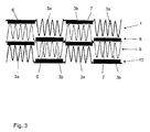
- FIG. 3 four PTC ceramic / corrugated fin units 1, 8, 9, 10 are positioned one above the other.
- the second PTC ceramic / corrugated fin unit 8 is opposite the first PTC ceramic / corrugated fin unit 1 rotated in the longitudinal direction by 180 ° and arranged offset at the same time.
- the corrugated portion 3b of the second PTC ceramic / corrugated fin unit 8 is directly opposite to the PTC ceramic 7 of the first PTC ceramic / corrugated fin unit 1, while the PTC ceramic 6 of the second PTC ceramic / Corrugated rib unit 8 is the corrugated portion 3a of the first PTC ceramic / corrugated fin unit 1 opposite.
- the corrugated portions 3a of the first PTC ceramic / corrugated fin unit 1 and the corrugated portions 3b of the second PTC ceramic / corrugated fin unit 8 have electrically opposite potentials.
- the first and second PTC ceramic / corrugated fin units 1 and 8 form a rectangular module.
- This module can be extended by any further PTC ceramic / corrugated fin units 9, 10, of which in FIG. 3 only two more are shown.
- PTC ceramic / corrugated fin units 9, 10 When stacking these PTC ceramic / corrugated fin units 9, 10, it must always be ensured that the corrugated areas 3a, 3b always face a PTC ceramic 6, 7. In addition, it is ensured that a PTC ceramic 6 or 7 in its longitudinal extent is always surrounded by two corrugated regions 3a and 3b, which are acted upon by opposite electrical potentials. As a result, in addition to safe operation of the PTC device, good heat dissipation is also realized.
Landscapes
- Engineering & Computer Science (AREA)
- Microelectronics & Electronic Packaging (AREA)
- Resistance Heating (AREA)
- Thermistors And Varistors (AREA)
Abstract
Description
- Die Erfindung betrifft eine PTC-Vorrichtung nach dem Oberbegriff von Anspruch 1.
- Als Kaltleiter, wie PTC-Widerstände oder PTC-Thermistore (PTC - Positive Temperature Coefficient) werden stromleitende Materialien bezeichnet, die bei tieferen Temperaturen den Strom besser leiten können als bei hohen. Ihr elektrischer Widerstand vergrößert sich bei steigender Temperatur. Dabei verfügen PTC-Elemente, die auf Keramikbasis hergestellt werden, über einen nicht linearen Widerstandsverlauf, welcher dazu genutzt wird, diese als Heizelement zu benutzen.
- Für Elektrofahrzeuge stellen solche PTC-Zuheizer eine Möglichkeit dar, ohne Mitführung eines Brennstoffes wie Benzin, Bioethanol etc. den Heizbedarf der Fahrerkabine elnes Kraftfahrzeuges in den kälteren Jahreszeiten zu decken. Die PTC-Vorrichtungen sind dabei so aufgebaut, dass eine PTC-Keramik zwischen zwei elektrisch leitende Kontaktflächen geklebt oder verspannt ist. Diese Kontaktflächen versorgen die PTC-Keramik mit elektrischem Strom. Zur Wärmeableitung ist eine Wellrippe vorgesehen, die am Kontaktblech verklebt oder verspannt ist.
- Aufgrund der Verwendung von mehreren Kontaktflächen und Wellrippen ist das Gewicht einer solchen PTC-Vorrichtung recht hoch.
- Es ist die Aufgabe der Erfindung, eine PTC-Vorrichtung zu schaffen, die zuverlässig als PTC-Heizer, vorzugsweise in einem Kraftfahrzeug, arbeitet und trotzdem ein geringeres Gewicht aufweist.
- Dies wird erreicht mit den Merkmalen von Anspruch 1, wonach das Wärme ableitende Element als elektrisch leitendes Kontaktelement ausgebildet ist. Da das elektrisch leitende Kontaktelement und das Wärme leitende Element nur ein einziges Bauteil darstellen, reduziert sich das Gewicht dieser PTC-Vorrichtung. Aufgrund der verminderten Anzahl von einzelnen Bauelementen reduzieren sich die Herstellungskosten.
- Vorteilhafterweise weist das Wärme ableitende Element wenigstens einen flächigen Bereich zur Aufnahme der PTC-Keramik auf. Da das Wärme ableitende Element vorzugsweise als Stanzblechteil hergestellt wird, lassen sich solche flächigen Bereiche einfach erzeugen. Die flächigen Bereiche des Wärme ableitenden Elementes weisen dabei solche Abmaße auf, dass die PTC-Keramik vollständig auf dem flächigen Bereich angeordnet werden kann, so dass die PTC-Keramik ausreichend mit elektrischem Strom versorgt und gleichzeitig eine zuverlässige Wärmeableitung von der PTC-Keramik gewährleistet wird.
- In einer Ausgestaltung schließt sich der flächige Bereich an einen gewellten Bereich des Wärme ableitenden Elementes an. Eine solche Form lässt sich einfach durch einen Stanz-Biege-Prozess eines Blechformteiles erzeugen, was die Herstellungskosten für die PTC-Vorrichtung weiter reduziert.
- In einer Variante ist die PTC-Keramik mit dem flächigen Bereich des Wärme ableitenden Elementes stoffschlüssig oder formschlüssig oder kraftschlüssig verbunden. Dabei ist von besonderer Bedeutung, dass die PTC-Keramik, insbesondere bei deren Verwendung in einem Kraftfahrzeug, erschütterungsfest auf dem Wärme ableitenden Element angeordnet ist.
- In einer besonders einfachen Ausführung ist die PTC-Keramik mit dem flächigen Bereich des Wärme ableitenden Elementes verklebt, was den Herstellungsprozess vereinfacht.
- In einer Weiterbildung ist das Wärme ableitende Element als Wellrippe ausgebildet, wobei zwei PTC-Keramik/Wellrippe-Einheiten zueinander versetzt angeordnet sind, wobei der gewellte Bereich der ersten PTC-Keramik/Wellrippe-Einheit direkt der PTC-Keramik der zweiten PTC-Keramik/Wellrippe-Einheit gegenüberliegt. Aufgrund dessen, dass die beiden PTC-Keramik/Wellrippe-Einheiten umgedreht und versetzt zueinander zusammengebaut sind, entsteht ein rechteckiges Modul, welches bei der weiteren Bearbeitung einfach zu handhaben ist.
- Ein beliebig großes Modul, das aus mehreren rechteckigen Modulen besteht, wird realisiert, wenn mehrere der PCT-Keramik/Wellrippe-Einheiten übereinander positioniert sind, wobei die PCT-Keramiken einander zugewandt sind und immer zwei übereinanderliegende PTO-Keramik/Wellrippe-Einheiten zueinander versetzt angeordnet sind, wobei der gewellte Bereich der ersten PTC-Keramik/Wellrippe-Einheit direkt der PTC-Keramik der zweiten PTC-Keramik/Wellrippe-Einheit gegenüberliegt.
- Weitere vorteilhafte Ausgestaltungen sind durch die nachfolgende Figurenbeschreibung und durch die Unteransprüche beschrieben.
- Nachstehend wird die Erfindung auf der Grundlage zumindest eines Ausführungsbeispiels anhand der Zeichnung näher erläutert. Es zeigen:
- Fig. 1
- ein erstes Ausführungsbeispiel einer erfindungsgemäßen Vorrichtung,
- Fig. 2
- eine erfindungsgemäße Wellrippe,
- Fig. 3
- ein weiteres Ausführungsbeispiel einer erfindungsgemäßen Vorrichtung.
- Die
Figur 1 zeigt ein erstes Ausführungsbeispiel einer erfindungsgemäßen PTC-Vorrichtung, welche als PTC-Keramik/Wellrippe-Einheit 1 ausgebildet ist. Das Wärme ableitende Element weist die Form einer Wellrippe 2 auf und besitzt einen gewellten Bereich 3, an welchen sich beidseitig je ein flächiger Bereich 4, 5 anschließt (Figur 2 ). Die Wellrippe 2 ist dabei einstückig als Blechformteil ausgebildet und besteht aus einem elektrisch leitenden Material. Auf den flächigen Bereichen 4, 5 ist jeweils eine PTC-Keramik 6, 7 vollflächig angeordnet, d. h. dass jede PTC-Keramik 6 bzw. 7 mit ihrer gesamten Ausdehnung auf je einem flächigen Bereich 4, 5 aufliegt. Durch diesen großflächigen Kontakt wird die PTC-Keramik 6, 7 mit elektrischem Strom versorgt. Der gewellte Bereich 3 der Wellrippe 2 dient der Abfuhr der Wärme, welche durch die Erhitzung der PTC-Keramik 6, 7 durch den elektrischen Strom erzeugt wird. Da die flächigen Bereiche 4, 5 und der gewellte Bereich 3 ein einziges Bauteil bilden, wird die Wärme von den flächigen Bereichen 4, 5 direkt auf den gewellten Bereich 3 abgeführt, welcher durch die wellige Ausführung eine große Oberfläche und somit einen guten Kontakt mit der Umgebung aufweist, an welche die Wärme abgegeben wird. - In
Figur 3 sind vier PTC-Keramik/Wellrippe-Einheiten 1, 8, 9, 10 übereinander positioniert. Dabei ist die zweite PTC-Keramik/Wellrippe-Einheit 8 gegenüber der ersten PTC-Keramik/Wellrippe-Einheit 1 in Längsrichtung um 180° verdreht und gleichzeitig versetzt angeordnet. Dies führt dazu, dass der gewellte Bereich 3b der zweiten PTC-Keramik/Wellrippe-Einheit 8 direkt gegenüber der PTC-Keramik 7 der ersten PTC-Keramik/Wellrippe-Einheit 1 liegt, während die PTC-Keramik 6 der zweiten PTC-Keramik/Wellrippe-Einheit 8 dem gewellten Bereich 3a der ersten PTC-Keramik/Wellrippe-Einheit 1 gegenüber liegt. Die gewellten Bereiche 3a der ersten PTC-Keramik/Wellrippe-Einheit 1 und die gewellten Bereiche 3b der zweiten PTC-Keramik/Wellrippe-Einheit 8 weisen dabei elektrisch entgegengesetzte Potentiale auf. - Die erste und die zweite PTC-Keramik/Wellrippen-Einheit 1 und 8 bilden dabei ein rechteckiges Modul. Dieses Modul kann durch beliebig weitere PTC-Keramik/Wellrippe-Einheiten 9, 10 erweitert werden, von denen in
Figur 3 nur noch zwei weitere dargestellt sind. Bei der Stapelung dieser PTC-Keramik/Wellrippe-Einheiten 9, 10 ist immer sicherzustellen, dass die gewellten Bereiche 3a, 3b immer einer PTC-Keramik 6, 7 gegenüberliegen. Darüber hinaus wird sichergestellt, dass eine PTC-Keramik 6 bzw. 7 in ihrer Längserstreckung immer von zwei gewellten Bereichen 3a bzw. 3b umgeben ist, die mit entgegengesetzten elektrischen Potentialen beaufschlagt sind. Dadurch wird neben einer sicheren Funktionsweise der PTC-Vorrichtung auch eine gute Wärmeabfuhr realisiert. - Aufgrund des Entfallens von zusätzlichen Bauteilen in Form der separaten Kontaktfläche ermöglicht die beschriebene Lösung eine Kosten- und Gewichtsreduzierung.
Claims (7)
- PTC-Vorrichtung, mit einer PTC-Keramik (6, 7), die mit einem elektrisch leitenden Kontaktelement verbunden ist, und einem Wärme ableitenden Element (3), dadurch gekennzeichnet, dass
das Wärme ableitende Element (3) als elektrisch leitendes Kontaktelement ausgebildet ist. - PTC-Vorrichtung nach Anspruch 1,
dadurch gekennzeichnet, dass
das Wärme ableitende Element (3) wenigstens einen flächigen Bereich (4, 5) zur Aufnahme der PTC-Keramik (6, 7) aufweist. - PTC-Vorrichtung nach Anspruch 2,
dadurch gekennzeichnet, dass
der flächige Bereich (4, 5) sich an einen gewellten Bereich (3a, 3b) des Wärme ableitenden Elementes (3) anschließt. - PTC-Vorrichtung nach Anspruch 2 oder 3,
dadurch gekennzeichnet, dass
die PTC-Keramik (6, 7) mit dem flächigen Bereich (4, 5) des Wärme ableitenden Elementes (3) stoffschlüssig oder formschlüssig oder kraftschlüssig verbunden ist. - PTC-Vorrichtung nach Anspruch 4,
dadurch gekennzeichnet, dass
die PTC-Keramik (6, 7) mit dem flächigen Bereich (4, 5) des Wärme ableitenden Elementes (3) verklebt ist. - PTC-Vorrichtung nach mindestens einem der vorhergehenden Ansprüche,
dadurch gekennzeichnet, dass
das Wärme ableitende Element als Wellrippe (3) ausgebildet ist, wobei zwei PTC-Keramik/Wellrippe-Einheiten (1, 8) zueinander versetzt angeordnet sind, wobei der gewellte Bereich (3a) der ersten PTC-Keramik/Wellrippe-Einheit (1) direkt der PTC-Keramik (6) der zweiten PTC-Keramik/Wellrippe-Einheit (8) gegenüberliegt. - PTC-Vorrichtung nach Anspruch 6,
dadurch gekennzeichnet, dass
mehrere der PTC-Keramik/Wellrippe-Einheiten (1, 8, 9, 10) übereinander positioniert sind, wobei immer zwei übereinanderliegende PTC-Keramik/Wellrippen-Einheiten (1, 8; 9, 10) zueinander versetzt angeordnet sind, wobei die PTC-Keramiken (6, 7) einander zugewandt sind und der gewellte Bereich (3a) der ersten PTC-Keramik/Wellrippe-Einheit (1, 9) direkt der PTC-Keramik (6) der zweiten PTC-Keramik/Wellrippe-Einheit (8, 10) gegenüberliegt.
Priority Applications (1)
| Application Number | Priority Date | Filing Date | Title |
|---|---|---|---|
| EP20130290087 EP2793241A1 (de) | 2013-04-18 | 2013-04-18 | PTC-Vorrichtung |
Applications Claiming Priority (1)
| Application Number | Priority Date | Filing Date | Title |
|---|---|---|---|
| EP20130290087 EP2793241A1 (de) | 2013-04-18 | 2013-04-18 | PTC-Vorrichtung |
Publications (1)
| Publication Number | Publication Date |
|---|---|
| EP2793241A1 true EP2793241A1 (de) | 2014-10-22 |
Family
ID=48534301
Family Applications (1)
| Application Number | Title | Priority Date | Filing Date |
|---|---|---|---|
| EP20130290087 Withdrawn EP2793241A1 (de) | 2013-04-18 | 2013-04-18 | PTC-Vorrichtung |
Country Status (1)
| Country | Link |
|---|---|
| EP (1) | EP2793241A1 (de) |
Citations (4)
| Publication number | Priority date | Publication date | Assignee | Title |
|---|---|---|---|---|
| DE2740691A1 (de) * | 1976-09-09 | 1978-03-16 | Texas Instruments Inc | Vergaseranordnung und darin verwendbare widerstandsvorrichtung |
| EP1225080A2 (de) * | 2001-01-22 | 2002-07-24 | David + Baader DBK GmbH | Schutzelement in einem elektrischen Schaltkreis |
| EP2346304A1 (de) * | 2010-01-15 | 2011-07-20 | Behr GmbH & Co. KG | Wärmeübertrager |
| EP2506660A1 (de) * | 2011-03-31 | 2012-10-03 | Behr France Rouffach SAS | Wärmeübertrager |
-
2013
- 2013-04-18 EP EP20130290087 patent/EP2793241A1/de not_active Withdrawn
Patent Citations (4)
| Publication number | Priority date | Publication date | Assignee | Title |
|---|---|---|---|---|
| DE2740691A1 (de) * | 1976-09-09 | 1978-03-16 | Texas Instruments Inc | Vergaseranordnung und darin verwendbare widerstandsvorrichtung |
| EP1225080A2 (de) * | 2001-01-22 | 2002-07-24 | David + Baader DBK GmbH | Schutzelement in einem elektrischen Schaltkreis |
| EP2346304A1 (de) * | 2010-01-15 | 2011-07-20 | Behr GmbH & Co. KG | Wärmeübertrager |
| EP2506660A1 (de) * | 2011-03-31 | 2012-10-03 | Behr France Rouffach SAS | Wärmeübertrager |
Similar Documents
| Publication | Publication Date | Title |
|---|---|---|
| EP3079442B1 (de) | Elektrische heizvorrichtung und rahmen hierfür | |
| DE102009056607B4 (de) | Zellverbinderdeckel und Hochstromzellanordnung mit einem Zellverbinderdeckel | |
| EP3455693B1 (de) | Vorrichtung zur temperaturregelung | |
| DE102015220759A1 (de) | Wärmeübertrager, insbesondere thermoelektrische Wärmepumpe, zum Temperieren einer Batterie | |
| DE102018209586A1 (de) | Elektronisches Bauteil mit verbesserter Kühlleistung und Kraftfahrzeug mit zumindest einem elektronischen Bauteil | |
| EP3451790A1 (de) | Vorrichtung mit beheizbarer streulichtblende | |
| EP3295768B1 (de) | Heizeinrichtung zum beheizen des fahrzeuginnenraums eines kraftfahrzeugs | |
| DE102009043526A1 (de) | Vorrichtung zur elektrischen Energiespeicherung | |
| DE102013209431A1 (de) | Leistungshalbleitermodul und Verfahren zur Herstellung eines Leistungshalbleitermoduls | |
| DE10118599B4 (de) | Elektrische Heizeinrichtung | |
| DE102018212012A1 (de) | Wärmeerzeugendes Element und Verfahren zu dessen Herstellung | |
| EP2728627A1 (de) | Verbindungseinrichtung und Anordnung hiermit und mit einem Photovoltaikmodul | |
| DE102015225584A1 (de) | Startvorrichtung für eine Brennkraftmaschine | |
| DE102020202195A1 (de) | Elektrische Heizeinrichtung | |
| EP2961013B1 (de) | Vorrichtung zur aufnahme elektrischer geräte mit mindestens einem kühlkörper | |
| DE102018127202B4 (de) | PTC-Heizung und System | |
| DE102014211977A1 (de) | Batteriemodul und Verfahren zu dessen Herstellung | |
| DE102014118402A1 (de) | Kühleinrichtung und Energiespeicher | |
| EP1457743B1 (de) | Elektrische Heizeinrichtung, insbesondere für ein Kraftfahrzeug | |
| DE102018205354A1 (de) | PTC-Heizmodul zur Erwärmung eines Fluids | |
| DE102016203773B4 (de) | Einrichtung zum Halten und Kühlen wenigstens eines elektrischen Energiespeichers, Energiespeicheranordnung | |
| DE102012018088A1 (de) | Vorrichtung zum elektrischen Kontaktieren von prismatischen Batterieeinzelzellen | |
| DE102024133117A1 (de) | Kühlanordnung | |
| DE102009055084A1 (de) | Heizeinrichtung für einen Kraftstoff-Filter | |
| EP4255110A1 (de) | Ptc-heizeinrichtung und elektrische heizvorrichtung umfassend eine solche |
Legal Events
| Date | Code | Title | Description |
|---|---|---|---|
| PUAI | Public reference made under article 153(3) epc to a published international application that has entered the european phase |
Free format text: ORIGINAL CODE: 0009012 |
|
| 17P | Request for examination filed |
Effective date: 20130418 |
|
| AK | Designated contracting states |
Kind code of ref document: A1 Designated state(s): AL AT BE BG CH CY CZ DE DK EE ES FI FR GB GR HR HU IE IS IT LI LT LU LV MC MK MT NL NO PL PT RO RS SE SI SK SM TR |
|
| AX | Request for extension of the european patent |
Extension state: BA ME |
|
| RAP1 | Party data changed (applicant data changed or rights of an application transferred) |
Owner name: MAHLE BEHR FRANCE ROUFFACH S.A.S |
|
| R17P | Request for examination filed (corrected) |
Effective date: 20150422 |
|
| RBV | Designated contracting states (corrected) |
Designated state(s): AL AT BE BG CH CY CZ DE DK EE ES FI FR GB GR HR HU IE IS IT LI LT LU LV MC MK MT NL NO PL PT RO RS SE SI SK SM TR |
|
| 17Q | First examination report despatched |
Effective date: 20170529 |
|
| GRAP | Despatch of communication of intention to grant a patent |
Free format text: ORIGINAL CODE: EPIDOSNIGR1 |
|
| RIC1 | Information provided on ipc code assigned before grant |
Ipc: H01C 1/14 20060101AFI20180109BHEP Ipc: H05B 3/24 20060101ALI20180109BHEP |
|
| INTG | Intention to grant announced |
Effective date: 20180215 |
|
| STAA | Information on the status of an ep patent application or granted ep patent |
Free format text: STATUS: THE APPLICATION IS DEEMED TO BE WITHDRAWN |
|
| 18D | Application deemed to be withdrawn |
Effective date: 20180626 |