EP2793214A1 - Flexible display device and method of controlling the same - Google Patents
Flexible display device and method of controlling the same Download PDFInfo
- Publication number
- EP2793214A1 EP2793214A1 EP13188558.4A EP13188558A EP2793214A1 EP 2793214 A1 EP2793214 A1 EP 2793214A1 EP 13188558 A EP13188558 A EP 13188558A EP 2793214 A1 EP2793214 A1 EP 2793214A1
- Authority
- EP
- European Patent Office
- Prior art keywords
- display area
- display
- unit
- image
- area
- Prior art date
- Legal status (The legal status is an assumption and is not a legal conclusion. Google has not performed a legal analysis and makes no representation as to the accuracy of the status listed.)
- Ceased
Links
Images




Classifications
-
- G—PHYSICS
- G09—EDUCATION; CRYPTOGRAPHY; DISPLAY; ADVERTISING; SEALS
- G09G—ARRANGEMENTS OR CIRCUITS FOR CONTROL OF INDICATING DEVICES USING STATIC MEANS TO PRESENT VARIABLE INFORMATION
- G09G3/00—Control arrangements or circuits, of interest only in connection with visual indicators other than cathode-ray tubes
- G09G3/03—Control arrangements or circuits, of interest only in connection with visual indicators other than cathode-ray tubes specially adapted for displays having non-planar surfaces, e.g. curved displays
- G09G3/035—Control arrangements or circuits, of interest only in connection with visual indicators other than cathode-ray tubes specially adapted for displays having non-planar surfaces, e.g. curved displays for flexible display surfaces
-
- H—ELECTRICITY
- H10—SEMICONDUCTOR DEVICES; ELECTRIC SOLID-STATE DEVICES NOT OTHERWISE PROVIDED FOR
- H10K—ORGANIC ELECTRIC SOLID-STATE DEVICES
- H10K59/00—Integrated devices, or assemblies of multiple devices, comprising at least one organic light-emitting element covered by group H10K50/00
- H10K59/10—OLED displays
- H10K59/12—Active-matrix OLED [AMOLED] displays
- H10K59/121—Active-matrix OLED [AMOLED] displays characterised by the geometry or disposition of pixel elements
-
- G—PHYSICS
- G06—COMPUTING OR CALCULATING; COUNTING
- G06F—ELECTRIC DIGITAL DATA PROCESSING
- G06F1/00—Details not covered by groups G06F3/00 - G06F13/00 and G06F21/00
- G06F1/16—Constructional details or arrangements
- G06F1/1613—Constructional details or arrangements for portable computers
- G06F1/1633—Constructional details or arrangements of portable computers not specific to the type of enclosures covered by groups G06F1/1615 - G06F1/1626
- G06F1/1637—Details related to the display arrangement, including those related to the mounting of the display in the housing
- G06F1/1652—Details related to the display arrangement, including those related to the mounting of the display in the housing the display being flexible, e.g. mimicking a sheet of paper, or rollable
-
- G—PHYSICS
- G09—EDUCATION; CRYPTOGRAPHY; DISPLAY; ADVERTISING; SEALS
- G09G—ARRANGEMENTS OR CIRCUITS FOR CONTROL OF INDICATING DEVICES USING STATIC MEANS TO PRESENT VARIABLE INFORMATION
- G09G3/00—Control arrangements or circuits, of interest only in connection with visual indicators other than cathode-ray tubes
- G09G3/20—Control arrangements or circuits, of interest only in connection with visual indicators other than cathode-ray tubes for presentation of an assembly of a number of characters, e.g. a page, by composing the assembly by combination of individual elements arranged in a matrix no fixed position being assigned to or needed to be assigned to the individual characters or partial characters
-
- G—PHYSICS
- G09—EDUCATION; CRYPTOGRAPHY; DISPLAY; ADVERTISING; SEALS
- G09G—ARRANGEMENTS OR CIRCUITS FOR CONTROL OF INDICATING DEVICES USING STATIC MEANS TO PRESENT VARIABLE INFORMATION
- G09G3/00—Control arrangements or circuits, of interest only in connection with visual indicators other than cathode-ray tubes
- G09G3/20—Control arrangements or circuits, of interest only in connection with visual indicators other than cathode-ray tubes for presentation of an assembly of a number of characters, e.g. a page, by composing the assembly by combination of individual elements arranged in a matrix no fixed position being assigned to or needed to be assigned to the individual characters or partial characters
- G09G3/22—Control arrangements or circuits, of interest only in connection with visual indicators other than cathode-ray tubes for presentation of an assembly of a number of characters, e.g. a page, by composing the assembly by combination of individual elements arranged in a matrix no fixed position being assigned to or needed to be assigned to the individual characters or partial characters using controlled light sources
- G09G3/30—Control arrangements or circuits, of interest only in connection with visual indicators other than cathode-ray tubes for presentation of an assembly of a number of characters, e.g. a page, by composing the assembly by combination of individual elements arranged in a matrix no fixed position being assigned to or needed to be assigned to the individual characters or partial characters using controlled light sources using electroluminescent panels
- G09G3/32—Control arrangements or circuits, of interest only in connection with visual indicators other than cathode-ray tubes for presentation of an assembly of a number of characters, e.g. a page, by composing the assembly by combination of individual elements arranged in a matrix no fixed position being assigned to or needed to be assigned to the individual characters or partial characters using controlled light sources using electroluminescent panels semiconductive, e.g. using light-emitting diodes [LED]
- G09G3/3208—Control arrangements or circuits, of interest only in connection with visual indicators other than cathode-ray tubes for presentation of an assembly of a number of characters, e.g. a page, by composing the assembly by combination of individual elements arranged in a matrix no fixed position being assigned to or needed to be assigned to the individual characters or partial characters using controlled light sources using electroluminescent panels semiconductive, e.g. using light-emitting diodes [LED] organic, e.g. using organic light-emitting diodes [OLED]
- G09G3/3225—Control arrangements or circuits, of interest only in connection with visual indicators other than cathode-ray tubes for presentation of an assembly of a number of characters, e.g. a page, by composing the assembly by combination of individual elements arranged in a matrix no fixed position being assigned to or needed to be assigned to the individual characters or partial characters using controlled light sources using electroluminescent panels semiconductive, e.g. using light-emitting diodes [LED] organic, e.g. using organic light-emitting diodes [OLED] using an active matrix
- G09G3/3233—Control arrangements or circuits, of interest only in connection with visual indicators other than cathode-ray tubes for presentation of an assembly of a number of characters, e.g. a page, by composing the assembly by combination of individual elements arranged in a matrix no fixed position being assigned to or needed to be assigned to the individual characters or partial characters using controlled light sources using electroluminescent panels semiconductive, e.g. using light-emitting diodes [LED] organic, e.g. using organic light-emitting diodes [OLED] using an active matrix with pixel circuitry controlling the current through the light-emitting element
-
- G—PHYSICS
- G09—EDUCATION; CRYPTOGRAPHY; DISPLAY; ADVERTISING; SEALS
- G09G—ARRANGEMENTS OR CIRCUITS FOR CONTROL OF INDICATING DEVICES USING STATIC MEANS TO PRESENT VARIABLE INFORMATION
- G09G5/00—Control arrangements or circuits for visual indicators common to cathode-ray tube indicators and other visual indicators
- G09G5/02—Control arrangements or circuits for visual indicators common to cathode-ray tube indicators and other visual indicators characterised by the way in which colour is displayed
- G09G5/06—Control arrangements or circuits for visual indicators common to cathode-ray tube indicators and other visual indicators characterised by the way in which colour is displayed using colour palettes, e.g. look-up tables
-
- H—ELECTRICITY
- H10—SEMICONDUCTOR DEVICES; ELECTRIC SOLID-STATE DEVICES NOT OTHERWISE PROVIDED FOR
- H10K—ORGANIC ELECTRIC SOLID-STATE DEVICES
- H10K59/00—Integrated devices, or assemblies of multiple devices, comprising at least one organic light-emitting element covered by group H10K50/00
- H10K59/10—OLED displays
- H10K59/12—Active-matrix OLED [AMOLED] displays
- H10K59/122—Pixel-defining structures or layers, e.g. banks
-
- H—ELECTRICITY
- H10—SEMICONDUCTOR DEVICES; ELECTRIC SOLID-STATE DEVICES NOT OTHERWISE PROVIDED FOR
- H10K—ORGANIC ELECTRIC SOLID-STATE DEVICES
- H10K59/00—Integrated devices, or assemblies of multiple devices, comprising at least one organic light-emitting element covered by group H10K50/00
- H10K59/30—Devices specially adapted for multicolour light emission
- H10K59/38—Devices specially adapted for multicolour light emission comprising colour filters or colour changing media [CCM]
-
- G—PHYSICS
- G09—EDUCATION; CRYPTOGRAPHY; DISPLAY; ADVERTISING; SEALS
- G09G—ARRANGEMENTS OR CIRCUITS FOR CONTROL OF INDICATING DEVICES USING STATIC MEANS TO PRESENT VARIABLE INFORMATION
- G09G2300/00—Aspects of the constitution of display devices
- G09G2300/08—Active matrix structure, i.e. with use of active elements, inclusive of non-linear two terminal elements, in the pixels together with light emitting or modulating elements
- G09G2300/0809—Several active elements per pixel in active matrix panels
- G09G2300/0819—Several active elements per pixel in active matrix panels used for counteracting undesired variations, e.g. feedback or autozeroing
-
- G—PHYSICS
- G09—EDUCATION; CRYPTOGRAPHY; DISPLAY; ADVERTISING; SEALS
- G09G—ARRANGEMENTS OR CIRCUITS FOR CONTROL OF INDICATING DEVICES USING STATIC MEANS TO PRESENT VARIABLE INFORMATION
- G09G2300/00—Aspects of the constitution of display devices
- G09G2300/08—Active matrix structure, i.e. with use of active elements, inclusive of non-linear two terminal elements, in the pixels together with light emitting or modulating elements
- G09G2300/0809—Several active elements per pixel in active matrix panels
- G09G2300/0842—Several active elements per pixel in active matrix panels forming a memory circuit, e.g. a dynamic memory with one capacitor
-
- G—PHYSICS
- G09—EDUCATION; CRYPTOGRAPHY; DISPLAY; ADVERTISING; SEALS
- G09G—ARRANGEMENTS OR CIRCUITS FOR CONTROL OF INDICATING DEVICES USING STATIC MEANS TO PRESENT VARIABLE INFORMATION
- G09G2300/00—Aspects of the constitution of display devices
- G09G2300/08—Active matrix structure, i.e. with use of active elements, inclusive of non-linear two terminal elements, in the pixels together with light emitting or modulating elements
- G09G2300/0809—Several active elements per pixel in active matrix panels
- G09G2300/0842—Several active elements per pixel in active matrix panels forming a memory circuit, e.g. a dynamic memory with one capacitor
- G09G2300/0861—Several active elements per pixel in active matrix panels forming a memory circuit, e.g. a dynamic memory with one capacitor with additional control of the display period without amending the charge stored in a pixel memory, e.g. by means of additional select electrodes
-
- G—PHYSICS
- G09—EDUCATION; CRYPTOGRAPHY; DISPLAY; ADVERTISING; SEALS
- G09G—ARRANGEMENTS OR CIRCUITS FOR CONTROL OF INDICATING DEVICES USING STATIC MEANS TO PRESENT VARIABLE INFORMATION
- G09G2310/00—Command of the display device
- G09G2310/02—Addressing, scanning or driving the display screen or processing steps related thereto
- G09G2310/0262—The addressing of the pixel, in a display other than an active matrix LCD, involving the control of two or more scan electrodes or two or more data electrodes, e.g. pixel voltage dependent on signals of two data electrodes
-
- G—PHYSICS
- G09—EDUCATION; CRYPTOGRAPHY; DISPLAY; ADVERTISING; SEALS
- G09G—ARRANGEMENTS OR CIRCUITS FOR CONTROL OF INDICATING DEVICES USING STATIC MEANS TO PRESENT VARIABLE INFORMATION
- G09G2320/00—Control of display operating conditions
- G09G2320/02—Improving the quality of display appearance
- G09G2320/0233—Improving the luminance or brightness uniformity across the screen
-
- G—PHYSICS
- G09—EDUCATION; CRYPTOGRAPHY; DISPLAY; ADVERTISING; SEALS
- G09G—ARRANGEMENTS OR CIRCUITS FOR CONTROL OF INDICATING DEVICES USING STATIC MEANS TO PRESENT VARIABLE INFORMATION
- G09G2320/00—Control of display operating conditions
- G09G2320/02—Improving the quality of display appearance
- G09G2320/0242—Compensation of deficiencies in the appearance of colours
-
- H—ELECTRICITY
- H10—SEMICONDUCTOR DEVICES; ELECTRIC SOLID-STATE DEVICES NOT OTHERWISE PROVIDED FOR
- H10K—ORGANIC ELECTRIC SOLID-STATE DEVICES
- H10K2102/00—Constructional details relating to the organic devices covered by this subclass
- H10K2102/301—Details of OLEDs
- H10K2102/311—Flexible OLED
Definitions
- the present invention relates to a flexible display device and a method of controlling the same, and more particularly, to a flexible display device improving an image quality when a display unit bends and a method of controlling the same.
- the light emitting type display devices include an organic light emitting display (OLED) device, a plasma display panel (PDP), a flat cathode ray tube (FCRT), a vacuum fluorescent display (VFD) panel and a light emitting diode (LED) panel
- the light receiving type display devices include a liquid crystal display (LCD) panel.
- the OLED has a wide viewing angle, excellent contrast and fast response speed. Accordingly, since the OLED is applied to the displays of mobile devices such as a digital camera, a video camera, a portable information terminal, a smart phone, an ultra slim notebook computer, and a tablet personal computer or electrical/electronic products such as an ultra thin television, it receives great attention.
- mobile devices such as a digital camera, a video camera, a portable information terminal, a smart phone, an ultra slim notebook computer, and a tablet personal computer or electrical/electronic products such as an ultra thin television, it receives great attention.
- the present invention provides a flexible display device that improves a non-uniform image quality when a display unit bends and a method of controlling the same.
- a flexible display device including: a display unit including a first display area and a second display area bendable with respect to the first display area; and a control unit correcting at least one of a brightness and colour coordinate of an image to be displayed in at least one of the first display area and the second display area according to a degree of bending between the first display area and the second display area.
- the flexible display device may further include a sensing unit measuring the degree of bending between the first display area and the second display area.
- the second display area may be bendable in a front or rear direction of the display unit, with respect to the first display area.
- the second display area may include a bending area bendable and a flat area having a flat form.
- the bending area may connect the flat area to the first display area.
- a degree of correction of a sub-pixel of the second display area may be larger as a pixel is farther away from the first display area.
- the control unit may correct an image to be displayed in the second display area to reduce a brightness of the image to be displayed in the second display area when the second display area bends toward a front direction of the display unit.
- the control unit may correct an image to be displayed in the second display area to reduce a blue colour of the image to be displayed in the second display area when the second display area bends toward a front direction of the display unit.
- the control unit may correct an image to be displayed in the second display area to increase a brightness of the image to be displayed in the second display area when the second display area bends toward a rear direction of the display unit.
- the control unit may correct an image to be displayed in the second display area to reduce a red colour of the image to be displayed in the second display area when the second display area bends toward a rear direction of the display unit.
- the flexible display device may further include a lookup table including correction values predetermined according to the degree of bending between the first display area and the second display area, wherein the control unit may receive a correction value corresponding to the degree of bending between the first display area and the second display area from a correction unit by using the lookup table and corrects an image to be displayed on the display unit.
- the flexible display device may further include a backplate attached to one side of the display unit to be bent together with the display unit. A portion of the backplate corresponding to an interface between the first display area and the second display area may be bent while the second display area is bent with respect to the first display area.
- the backplate may include a form variable unit including a bent unit that maintains a bending form even when the display unit is not bent.
- the bent unit may be disposed at the interface between the first display area and the second display area.
- a method of controlling a flexible display device including a first display area and a second display area bendable with respect to the first display area, the method including: measuring a degree of bending between the first display area and the second display area; correcting at least one of a brightness and colour coordinate of an image to be displayed in at least one of the first display area and the second display area according to the degree of bending to produce a corrected image; and displaying the corrected image.
- the second display area may be bendable in a front or rear direction of the display unit, with respect to the first display area.
- the second display area may include a bending area bendable and a flat area having a flat form.
- the bending area may connect the flat area to the first display area.
- a degree of correction of a pixel in the second display area may be larger as the pixel is farther away from the first display area.
- the correcting the at least one of the brightness and the colour coordinate may include correcting an image to be displayed in the second display area to reduce the brightness of the image to be displayed in the second display area when the second display area bends toward a front direction of the display unit.
- the correcting the at least one of the brightness and the colour coordinate may include correcting an image to be displayed in the second display area to reduce a blue colour of the image to be displayed in the second display area when the second display area bends toward a front direction of the display unit.
- the correcting the at least one of the brightness and the colour coordinate may include correcting an image to be displayed in the second display area to increase the brightness of the image to be displayed in the second display area when the second display area bends toward a rear direction of the display unit.
- the correcting the at least one of the brightness and the colour coordinate may include correcting an image to be displayed in the second display area to reduce a red colour of the image to be displayed in the second display area when the second display area bends toward a rear direction of the display unit.
- the flexible display device 10 includes a display unit 100, a gate driver 210, a data driver 250, a sensing unit 300, a correction unit 400, and a control unit 500.
- a plurality of scan lines SL1 to SLn uniformly spaced in rows and a plurality of data lines DL1 to DLm uniformly spaced in columns are arranged in a matrix.
- Sub-pixels subPX are arranged in a matrix (two-dimensional array) in the intersection areas of the scan lines SL1 to SLn and the data lines DL1 to DLm.
- An arrangement direction of the sub-pixels subPX in each row i.e., a direction along a scan line
- an arrangement direction of the sub-pixels subPX in each column i.e., a direction perpendicular to the scan line, is defined as a column direction.
- the sub-pixel subPX means a red pixel, a green pixel, or a blue pixel.
- a set of the red, green, and blue pixels is referred to as one pixel.
- a scan driver 210 generates scan signals and then, sequentially supplies them to the display unit 100 through the plurality of scan lines SL1 to SLn.
- the data driver 250 sequentially supplies data signals to the display unit 100 through the plurality of data lines DL1 to DLn.
- the data driver 250 coverts input image data DATA having a gradation inputted from the control unit 500 into a voltage or current form of a data signal.
- the sensing unit 300 measures the degree of bending between a first display area D1 and a second display area D2, and applies its result to the correction unit 400. Then, the correction unit 400 determines a correction value for a sub-pixel or pixel on the basis of the degree of bending between the first display area D1 and the second display area D2.
- the control unit 500 generates a scan control signal CS1 and a data control signal CS2 and then, delivers them to the scan driver 210 and the data driver 250, respectively. Accordingly, the scan driver 210 sequentially applies scan signals to a scan line, and the data driver 250 applies a data signal to each pixel.
- the control unit 500 receives a correction value from the correction unit 400, and corrects a data signal on the basis of the correction value, and then outputs the corrected data DATA to the data driver 250. Additionally, a first power ELVDD, a second power ELVSS, a light emission control signal EM, and an initialize signal Vint (shown in FIG. 5 ) may be applied to each pixel under a control of the control unit 500.
- the flexible display device 10 includes a flexible display unit 100 displaying an image.
- the display unit 100 may include at least one thin film transistor (TFT) and an organic light emitting display (OLED) device, but it is not limited thereto.
- TFT thin film transistor
- OLED organic light emitting display
- the flexible display device 10 may employ other types of display devices such as a liquid crystal display panel, a field emission display device, an electroluminescent display device, and an electrophoretic display device.
- the display unit 100 is combined with a touch screen, a display driver IC (DDI), a flexible printed circuit board (FPCB), a polarizing plate, and a window cover.
- the display unit 100 includes a first display area D1 and a second display area D2 at both sides of the first display area D1.
- the second display areas D2 may be disposed at the left and right sides of the first display area D1.
- the positions of the second display areas D2 are not limited thereto, and thus, may be disposed at the top and bottom sides of the first display area D1.
- the first display area D1 may be disposed at the right and the second display area D2 may be disposed at the left in the display unit 100, or the first display area D1 may be disposed at the top and the second display area D2 may be disposed at the bottom in the display unit 100. Also, their opposite arrangements are possible.
- the first display area D1 may be flat.
- the second display area D2 may include a bending area D21 that is bendable, and a flat area D22 that is flat.
- the bending area D21 connects the flat area D22 to the first display area D1. Therefore, the second display area D2 may rotate toward the front or rear direction of the display unit 100 with respect to the first display area D1. Even when the second display area D2 rotates with respect to the first display area D1, the flat area D22 of the second display area D2 may not bend.
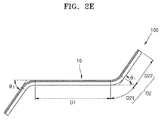
- the second display area D2 may bend at a predetermined angle ⁇ 1, ⁇ 2 or ⁇ 3, shown in FIGS. 2A through 2E , with respect to the first display area D1.
- the degree of bending of the second display areas D2 at both sides of the first display area D1 may be symmetric on the basis of the first display area D1 as shown in FIGS. 2B and 2C , or may be asymmetric as shown in FIGS. 2D and 2E .
- the bending angle of the display unit 100 may be fixed or may vary depending on an external impact.
- a casing 150 is installed at the bottom of the display unit 100 so as to mount the display unit 100.
- the casing 150 may be formed of any material having flexibility.
- a backplate 160 bending with the display unit 100 is installed at the bottom of the casing 150.
- the backplate 160 may have a bending unit, or bendable portion. Therefore, the second display area D2 may rotate on the basis of the bending unit.
- a user may bend the flexible display device 10 back and forth by applying a compressive stress to the edge of the flexible display device 10.
- a user may unbend (straighten) the flexible display device 10 by applying a compressive stress to the edge of the flexible display device 10. In such a way, the flexible display device 10 may be bent or unbent repeatedly depending on stress.
- FIG. 3 is a perspective view when a portion of the backplate 160 of FIG. 2A is cut off.
- FIG. 4A is a cross-sectional view taken along a line IV-IV when the backplate 160 of FIG. 3 unbends ie. straightens.
- FIG. 4B is a cross-sectional view taken along a line V-V when the backplate 160 of FIG. 3 unbends.
- the backplate 160 includes a form variable unit 161 and a housing unit 162.
- the backplate 160 may include a bending unit to maintain a bending state stably.
- the form variable unit 161 may include a bending unit 163 ( FIG. 4B ) in an area corresponding to the bending area D21 of the second display area D2.
- the form variable unit 161 may be formed of a metallic thin plate having flexibility ie. which can be bent into various shapes.
- the form variable unit 161 may be surrounded by the housing unit 162.
- the housing unit 162 is formed of a material having elasticity such as silicon or rubber.
- an adhesive layer formed of a material having elasticity may be formed between the display unit 100 and the form variable unit 161.
- the housing unit 162 surrounds the form variable unit 161 and the surface of the housing unit 162 may be flat to maintain the display unit 100 in a completely unbent state when the flexible display device 10 unbends. Therefore, the housing unit 162 may have a thickness so as to surround the form variable unit 161 over an entire area and maintain a predetermined width of the entire backplate 160.
- the form variable unit 161 may maintain a straight form in a width direction and a bending form in a length direction. In such a way, even when the display unit 100 is flat, since the form variable unit 161 maintains a bending form, ie. is in a bent state, to provide a rotation reference for the second display area D2, a state of the flexible display device 10 changes easily.
- the viewing angle of the second display area D2 may vary depending on the position of the display unit 100. Additionally, even when a user stays at the same position, according to the degree of bending of the display unit 100, the viewing angle of the second display area D2 may vary. Accordingly, when the same optical properties are displayed on the entire display unit 100 like a general flat type display unit, non-uniform image quality properties in brightness and saturation are displayed as an image is viewed with an actual eye. For example, according to the degree of bending of the display unit 100, compared to the first display area D1, the second display area D2 may have different brightness and saturation, and also, brightness and saturation may be different even in the second display area D2.
- the display unit 100 includes the sensing unit 300.
- the sensing unit 300 measures the degree of bending between the first display area D1 and the second display area D2, and changes a data signal of the second display area D2 on the basis of the measured degree of bending, thereby correcting a saturation and brightness difference occurring due to the bending of the display unit 100.
- the saturation correction may be performed by correcting chromaticity coordinates.
- At least one sensing unit 300 may be disposed in a boundary area of the first display area D1 and the second display area D2.
- the sensing unit 300 may be disposed in the bending area D21 of the second display area D2. Therefore, the sensing unit 300 measures the degree of bending between the first display area D1 and the second display area D2.
- the sensing unit 300 may be implemented using a bending sensor, for example a piezoelectric bending transducer.
- the correction unit 400 receives the degree of bending between the first display area D1 and the second display area D2, from the sensing unit 300.
- the correction unit 400 determines a correction value for correcting an image to be displayed on the first display area D1 and the second display area D2, on the basis of the received degree of bending.
- the correction unit 400 determines a correction value for correcting an image to be displayed on at least one of the first display area D1 and the second display area D2, so as to remove or minimize a saturation or brightness difference between the first display area D1 and the second display area D2.
- the correction value may include a saturation correction value for correcting saturation and a brightness correction value for correcting brightness.
- the saturation correction value may be applied by a sub-pixel unit, and the brightness correction value may be applied by a pixel unit.
- the correction unit 400 determines a correction value for correcting an image of the second display area, so as to allow an image to be displayed in the second display area D2 to have the same saturation and brightness as an image displayed on the first display area D1.
- the correction unit 400 may determine a brightness correction value for reducing brightness and a saturation correction value for reducing blue colour.
- the correction unit 400 determines a brightness correction value for increasing the brightness and a saturation correction value for reducing red colour, so as to allow an image to be displayed in the second display area D2 to have the same saturation and brightness as an image displayed on the first display area D1.
- the control unit 500 receives a correction value from the correction unit 400, and then outputs image data DATA corrected based on the correction value, to the data driver 250.
- the compensation unit 400 may need to correct an image of the second display area D2 according to the position of the second display area D2. For example, if a pixel (or a sub-pixel) in the second display area D2 is disposed farther away from the first display area D1, the correction unit 400 may more correct an image of the pixel.
- the correction unit 400 may pre-store a lookup table defining a correction value relationship between the degree of bending and a data signal applied to the first display area D1 and the second display area D2.
- the correction unit 400 may determine a correction value of a data signal for correcting saturation and brightness, with reference to the lookup table.
- the display device 10 On receiving a saturation and brightness correction request by a user's input while an image is displayed on the display unit 100, the display device 10 measures a bending angle with respect to a current frame by using the sensing unit 300, and corrects a saturation by each display area of the display unit 100, on the basis of the bending angle.
- the display device 10 measures a bending angle between the first display area D1 and the second display area D2 at a predetermined frame interval by using the sensing unit 300, and corrects a saturation by each display area of the display unit 100, on the basis of the bending angle.
- FIG. 5 is a circuit diagram of a sub-pixel according to an embodiment of the present invention.
- FIG. 6 is a cross-sectional view of a sub-pixel circuit of FIG. 5 .
- one sub-pixel subPX of the display unit 100 may include six thin film transistors (TFTs) and one capacitor.
- TFTs thin film transistors
- the sub-pixel subPX includes a sub-pixel circuit 120 including a plurality of TFTs T1 through T6 and a storage capacitor Cst. Also, the sub-pixel subPX includes an organic light emitting display (OLED) device that emits light by receiving driving voltage through the sub-pixel circuit 120.
- OLED organic light emitting display
- the sub-pixel subPX includes a scan line 24 delivering a scan signal Sn, a previous scan line 14 delivering a previous scan signal Sn-1 to the initializing TFT T4, a light emission controlling line 34 delivering a light emission control signal EMn to the operation controlling TFT T5 and the light emission controlling TFT T6, a data line 16 intersecting the scan line 24 and delivering a data signal Dm, a driving voltage line 26 delivering a first power ELVDD and disposed almost in parallel to the data line 16, and an initializing voltage line 20 delivering an initializing voltage Vint to initialize the driving TFT T1.
- the TFTs T1 to T6 include the driving TFT T1, the switching TFT T2, the compensating TFT T3, the initializing TFT T4, the operation controlling TFT T5, and the light emission controlling TFT T6.
- a TFT is a PMOS TFT
- the driving TFT T1, the switching TFT T2, the compensating TFT T3, the initializing TFT T4, the operation controlling TFT T5, and the light emission controlling TFT T6 are formed along a semiconductor layer.
- the semiconductor layer is formed of polysilicon and includes a channel area undoped with an impurity and a source and drain area doped with an impurity at both sides of the channel area.
- the impurity varies depending on a type of a TFT, and an N type impurity or a P type impurity is possible.
- the semiconductor layer includes a driving semiconductor layer of the driving TFT T1, a switching semiconductor layer of the switching TFT T2, a compensating semiconductor layer of the compensating TFT T3, an initializing semiconductor layer of the initializing TFT T4, an operation controlling semiconductor layer of the operation controlling TFT T5, and a light emission controlling semiconductor layer of the light emission controlling TFT T6.
- the driving TFT T1 includes a driving semiconductor layer A1, a driving gate electrode G1, a driving source electrode S1, and a driving drain electrode D1.
- the driving gate electrode G1 of the driving TFT T1 is connected to a first electrode Cst1 of the storage capacitor Cst.
- the driving source electrode S1 is connected to the driving voltage line 26 via the operation controlling TFT T5.
- the driving drain electrode D1 is electrically connected to an anode electrode of the OLED via the light emission controlling TFT T6.
- the driving TFT T1 receives the data signal Dm according to a switching operation of the switching TFT T2 and supplies a driving current Id to the OLED.
- the driving gate electrode G1 covers a channel area of the driving semiconductor layer A1, and a first insulating layer and a second insulating layer thereon are disposed between the driving semiconductor layer A1 and the driving gate electrode G1.
- the driving gate electrode G1 is connected to the first electrode Cst1 of the storage capacitor Cst by a connection means via a contact hole.
- the first electrode Cst1 of the storage capacitor Cst is disposed on the first insulating layer.
- the driving source electrode S1 corresponds to a driving source area doped with an impurity in the driving semiconductor layer A1 and the driving drain electrode D1 corresponds to a driving drain area doped with an impurity in the driving semiconductor layer A1.
- the switching TFT T2 includes a switching semiconductor layer A2, a switching gate electrode G2, a switching source electrode S2, and a switching drain electrode D2.
- the switching gate electrode G2 of the switching TFT T2 is connected to the scan line 24.
- the switching source electrode S2 is connected to the data line 16.
- the drain electrode D2 is connected to the source electrode S1 of the driving TFT T1 and also is connected to the driving voltage line 26 via the operation controlling TFT T5.
- the switching TFT T2 is turned on in response to the scan signal Sn received through the scan line 24, and then, performs a switching operation for delivering the data signal Dm delivered to the data line 16 to the driving source electrode S1 of the driving TFT T1.
- the switching source electrode S2 corresponds to a switching source area doped with an impurity in the switching semiconductor layer A2
- the switching drain electrode D2 corresponds to a switching drain area doped with an impurity in the switching semiconductor layer A2.
- the compensating TFT T3 includes a compensating semiconductor layer A3, a compensating gate electrode G3, a compensating source electrode S3, and a compensating drain electrode D3.
- the compensating gate electrode G3 of the compensating TFT T3 is connected to the scan line 24.
- the compensating source electrode S3 is connected to the driving drain electrode D1 of the driving TFT T1 and is connected to an anode electrode of the OLED via the light emission controlling TFT T6.
- the compensating drain electrode D3 is connected to the initializing drain electrode D4 of the initializing TFT T4 and the driving gate electrode G1 of the driving TFT T1.
- the compensating TFT T3 is turned on in response to the scan signal Sn received through the scan line 24, and then, connects the driving gate electrode G1 and the driving drain electrode D1 of the driving TFT T1, thereby connecting the driving TFT T1 to a diode.
- the compensating gate electrode G3 forms a dual gate electrode so as to prevent leakage current.
- the compensating source electrode S3 corresponds to a compensating source area doped with an impurity in the compensating semiconductor layer A3
- the compensating drain electrode D3 corresponds to a compensating drain area doped with an impurity in the compensating semiconductor layer A3.
- the initializing TFT T4 includes an initializing semiconductor layer A4, an initializing gate electrode G4, an initializing source electrode S4, and an initializing drain electrode D4.
- the initializing gate electrode G4 of the initializing TFT T4 is connected to the previous scan line 14.
- the initializing source electrode S4 is connected to the initializing voltage line 20.
- the initializing drain electrode D4 is connected to one end Cst1 of the storage capacitor Cst, the compensating drain electrode D3 of the compensating TFT T3, and the driving gate electrode G1 of the driving TFT T1.
- the initializing TFT T4 is turned on in response to the previous scan signal Sn-1 received through the previous scan line 14, and then, delivers an initializing voltage Vint to the driving gate electrode G1 of the driving TFT T1, so as to perform an initializing operation for initializing a voltage of the driving gate electrode G1 of the driving TFT T1.
- the initializing gate electrode G4 may be formed of a dual gate electrode.
- the operation controlling TFT T5 includes an operation controlling semiconductor layer A5, an operation controlling gate electrode G5, an operation controlling source electrode S5, and an operation controlling drain electrode D5.
- the operation controlling gate electrode G5 of the operation controlling TFT T5 is connected to the light emission controlling line 34.
- the operation controlling source electrode S5 is connected to the driving voltage line 26.
- the operation controlling drain electrode D5 is connected to the driving source electrode S1 of the driving TFT T1 and the switching drain electrode D2 of the switching TFT T2.
- the operation controlling source electrode S5 corresponds to an operation controlling source area doped with an impurity in the operation controlling semiconductor layer A5 and the operation controlling drain electrode D5 corresponds to an operation controlling drain area doped with an impurity in the operation controlling semiconductor layer A5.
- the light emission controlling TFT T6 includes a light emission controlling semiconductor layer A6, a light emission controlling gate electrode G6, a light emission controlling source electrode S6, and a light emission controlling drain electrode D6.
- the light emission controlling gate electrode G6 of the light emission controlling TFT T6 is connected to the light emission controlling line 34.
- the light emission controlling source electrode S6 is connected to the driving drain electrode D1 of the driving TFT T1 and the compensating source electrode S3 of the compensating TFT T3.
- the light emission controlling drain electrode D6 is electrically connected to an anode electrode of the OLED.
- the operation controlling TFT T5 and the light emission controlling TFT T6 are turned on simultaneously in response to a light emission control signal EMn received through the light emission controlling line 34, so that the first power ELVDD is delivered to the OLED so as to allow the driving current Id to flow in the OLED.
- the light emission controlling source electrode S6 corresponds to a light emission controlling source area doped with an impurity in the light emission controlling semiconductor layer A6 and the light emission controlling drain electrode D6 is connected to an anode electrode by a connection member.
- the first electrode Cst1 of the storage capacitor Cst is connected to the driving gate electrode G1 of the driving TFT T1, the compensating drain electrode D3 of the compensating TFT T3, and the initializing drain electrode D4 of the initializing TFT T4, through a connection node.
- the first electrode Cst1 is formed of a floating electrode having a island form, is formed of the same material as and is disposed at the same layer as the previous scan line 14, the light emission controlling line 34, the initializing gate electrode G4, the operation controlling gate electrode G5, and the light emission controlling gate electrode G6.
- the second electrode Cst2 of the storage capacitor Cst is connected to the driving voltage line 26.
- the second electrode Cst2 may be formed of a floating electrode having an island form and may be disposed to overlap the entire first electrode Cst1.
- the first electrode Cst2 is formed of the same material as and is disposed at the same layer as the initializing voltage line 20, the scan line 24, the driving gate electrode G1, the switching gate electrode G2, and the compensating gate electrode G3.
- the two insulating layers are disposed between the semiconductor layer and the gate electrode, so that a gate insulating layer thicker than one gate insulting layer of the initializing TFT T4, the operation controlling TFT T5, and the light emission controlling TFT T6 is disposed in the driving TFT T1, the switching TFT T2, and the compensating TFT T3.
- the cathode electrode of the OLED is connected to the second power ELVSS. Accordingly, the OLED receives the driving current Id from the driving TFT T1 and emits light to display an image.
- a low level previous scan signal Sn-1 is applied through the previous scan line 14 during an initializing period.
- the initializing TFT T4 is turned on in response to a low level previous scan signal Sn-1, and the initializing voltage Vint is applied from the initializing voltage line 20 to the gate electrode of the driving TFT T1 through the initializing TFT T4.
- the driving TFT T1 is initialized by the initializing voltage Vint.
- a low level scan signal Sn is applied through a scan line 24 during a data programming period.
- the switching TFT T2 and the compensating TFT T3 are turned on in response to the low level scan signal Sn.
- the driving TFT T1 is connected to a diode by the turned-on compensating TFT T3, and is forward-biased.
- a compensating voltage (Dm+Vth, Vth is a negative value) obtained by reducing the data signal Dm supplied from the data line 16 by a threshold voltage Vth of the driving TFT T1 is applied to the gate electrode of the driving TFT T1.
- the driving voltage ELVDD and the compensating voltage (Dm+Vth) are applied to both ends of the storage capacitor Cst, and charges corresponding to a voltage difference at both ends are stored in the storage capacitor Cst. Then, the light emission control signal En supplied from the light emission controlling line 34 changes from a high level into a low level during a light emitting period. Then, the operation controlling TFT T5 and the light emission controlling TFT T6 are turned on in response to the low level light emission control signal EMn during a light emitting period.
- the driving current Id occurs according to a voltage difference between a voltage of the gate electrode of the driving TFT T1 and the driving voltage ELVDD, and the driving current Id is supplied to the OLED through the light emission controlling TFT T6.
- a gate-source voltage Vgs of the driving TFT T1 is maintained as ⁇ (Dm+Vth)-ELVDD ⁇ by the storage capacitor Cst, and according to a current-voltage relationship of the driving TFT T1, the driving current Id is proportional to the square of a value ⁇ (Dm-ELVDD)2 ⁇ obtained by subtracting a threshold voltage from a gate-source voltage. That is, according to the data signal Dm, the luminance and luminous colour of the OLED may be controlled.
- the display device 10 adjusts the data signal Dm in correspondence to a bending angle of the display unit 100, so that image quality characteristics of the display unit 100 may become uniform.
- FIG. 7 is a flowchart illustrating a method of correcting an image as the display device 10 bends according to an embodiment of the present invention.
- the sensing unit 300 measures the degree of bending between the first display area D1 and the second display area D2 in operation S710.
- At least one bending sensor may be disposed in a boundary area of the first display area D1 and the second display area D2.
- the bending sensor measures the degree of bending between the first display area D1 and the second display area D2 and applies its result to the correction unit 400.
- the correction unit 400 determines a correction value to minimize a brightness and saturation difference between the first display area D1 and the second display area D2 in operation S720.
- the correction unit 400 may pre-store a lookup table which includes correction values for minimizing differences in brightness and saturation between the first display area D1 and the second display area D2 at every degree of bending. Therefore, the correction unit 400 may read brightness and saturation correction values from the lookup table, which correspond to the measurement value received from the sensing unit 300.
- the brightness and saturation correction values may be different based on the location of a pixel (or a sub-pixel). For example, the brightness and saturation correction values of a pixel may depend on a distance between the pixel and the first display area D1 or a distance between the pixel and the second display area D2.
- the correction unit 400 also may pre-store a lookup table made based on the locations of pixels.
- the control unit 500 corrects an image according to the correction value received from the correction unit 400, and then, displays the corrected image on the display unit 100 in operation S730.
- the correction unit 400 may adjust a data signal applied to at least one display area of the first display area D1 and the second display area D2, so as to minimize brightness and saturation differences between the first display area D1 and the second display area D2.
- the brightness correction of the first display area D1 and the second display area D2 may be performed by adjusting a voltage level of a data signal applied to the pixels of the first display area D1 and the second display area D2, and the saturation correction of the first display area D1 and the second display area D2 may be performed by adjusting a voltage level of a data signal applied to sub-pixels of the first display area D1 and the second display area D2.
- a degree of correction For example, a higher change of the brightness can be considered to as a higher degree of correction.
- the control unit when the brightness of the second display area D2 is greater than that of the first display area D1, the control unit lowers a data signal applied to a pixel of the second display area D2 by a predetermined level, so that the brightness of the second display area D2 may be lowered.
- the control unit 500 may further lower a voltage level of a data signal. Therefore, as pixels in the second display area D2 are farther away from the first display area D1, their brightness are corrected to be further lowered.
- the control unit when the saturation of the second display area D2 is tinged with more blue colour than that of the first display area D1, the control unit lowers a data signal applied to a blue sub-pixel of the second display area D2 by a predetermined level, so that the saturation of the second display area D2 may be changed.
- the control unit 500 may further lower a voltage level of a data signal.
- a brightness and saturation difference between the first display area D1 and the second display area occurs due to the bending angle of the display unit 100. Accordingly, by correcting data signals of the first display area D1 and the second display area, a brightness and saturation difference at each position due to the bending of the display unit 100 may be reduced.
- the embodiments of the present invention describe a display device including a sub-pixel configured with a PMOS TFT as an example, but the present invention is not limited thereto. That is, the present invention is also applied to a display device including a pixel configured with an NMOS TFT. In this case, by raising a data signal applied to a pixel by a predetermined level, saturation may be increased.
- the present invention is not limited thereto. It is apparent that according to a panel design, after a first display area and a second display area are divided into a plurality of areas, the degree of bending is measured in each area by using at least one bending sensor disposed in a boundary area, and then, a data signal is differently adjusted in each area on the basis of a measured result, so that an entire saturation of a flexible display unit may be uniform. Furthermore, a bending sensor may be disposed in an area corresponding to each pixel of the second display area.
- the embodiments of the present invention describe the driving TFT of the sub-pixel of FIG. 5 as an example, but the present invention is not limited thereto. It is apparent that the present invention may be applied to a pixel including a driving TFT that supplies driving current in connection to a light emitting device and a flexible display unit including the same.
Landscapes
- Engineering & Computer Science (AREA)
- Computer Hardware Design (AREA)
- Theoretical Computer Science (AREA)
- Physics & Mathematics (AREA)
- General Physics & Mathematics (AREA)
- Microelectronics & Electronic Packaging (AREA)
- General Engineering & Computer Science (AREA)
- Human Computer Interaction (AREA)
- Geometry (AREA)
- Electroluminescent Light Sources (AREA)
- Devices For Indicating Variable Information By Combining Individual Elements (AREA)
- Control Of Indicators Other Than Cathode Ray Tubes (AREA)
- Control Of El Displays (AREA)
Abstract
Description
- The present invention relates to a flexible display device and a method of controlling the same, and more particularly, to a flexible display device improving an image quality when a display unit bends and a method of controlling the same.
- In general, flat display devices are classified into light emitting type display devices and light receiving type display devices. The light emitting type display devices include an organic light emitting display (OLED) device, a plasma display panel (PDP), a flat cathode ray tube (FCRT), a vacuum fluorescent display (VFD) panel and a light emitting diode (LED) panel, and the light receiving type display devices include a liquid crystal display (LCD) panel.
- Among them, the OLED has a wide viewing angle, excellent contrast and fast response speed. Accordingly, since the OLED is applied to the displays of mobile devices such as a digital camera, a video camera, a portable information terminal, a smart phone, an ultra slim notebook computer, and a tablet personal computer or electrical/electronic products such as an ultra thin television, it receives great attention.
- Flexible display devices having portability and capable of being applied to various forms of devices are recently researched and developed as next generation display devices. Among them, an OLED technology based flexible display device is regarded as the most promising display device.
- The present invention provides a flexible display device that improves a non-uniform image quality when a display unit bends and a method of controlling the same.
- According to an aspect of the present invention, there is provided a flexible display device including: a display unit including a first display area and a second display area bendable with respect to the first display area; and a control unit correcting at least one of a brightness and colour coordinate of an image to be displayed in at least one of the first display area and the second display area according to a degree of bending between the first display area and the second display area.
- The flexible display device may further include a sensing unit measuring the degree of bending between the first display area and the second display area.
- The second display area may be bendable in a front or rear direction of the display unit, with respect to the first display area.
- The second display area may include a bending area bendable and a flat area having a flat form. The bending area may connect the flat area to the first display area.
- A degree of correction of a sub-pixel of the second display area may be larger as a pixel is farther away from the first display area.
- The control unit may correct an image to be displayed in the second display area to reduce a brightness of the image to be displayed in the second display area when the second display area bends toward a front direction of the display unit.
- The control unit may correct an image to be displayed in the second display area to reduce a blue colour of the image to be displayed in the second display area when the second display area bends toward a front direction of the display unit.
- The control unit may correct an image to be displayed in the second display area to increase a brightness of the image to be displayed in the second display area when the second display area bends toward a rear direction of the display unit.
- The control unit may correct an image to be displayed in the second display area to reduce a red colour of the image to be displayed in the second display area when the second display area bends toward a rear direction of the display unit.
- The flexible display device may further include a lookup table including correction values predetermined according to the degree of bending between the first display area and the second display area, wherein the control unit may receive a correction value corresponding to the degree of bending between the first display area and the second display area from a correction unit by using the lookup table and corrects an image to be displayed on the display unit.
- The flexible display device may further include a backplate attached to one side of the display unit to be bent together with the display unit. A portion of the backplate corresponding to an interface between the first display area and the second display area may be bent while the second display area is bent with respect to the first display area.
- The backplate may include a form variable unit including a bent unit that maintains a bending form even when the display unit is not bent. The bent unit may be disposed at the interface between the first display area and the second display area.
- According to another aspect of the present invention, there is provided a method of controlling a flexible display device including a first display area and a second display area bendable with respect to the first display area, the method including: measuring a degree of bending between the first display area and the second display area; correcting at least one of a brightness and colour coordinate of an image to be displayed in at least one of the first display area and the second display area according to the degree of bending to produce a corrected image; and displaying the corrected image.
- The second display area may be bendable in a front or rear direction of the display unit, with respect to the first display area.
- The second display area may include a bending area bendable and a flat area having a flat form. The bending area may connect the flat area to the first display area.
- A degree of correction of a pixel in the second display area may be larger as the pixel is farther away from the first display area.
- The correcting the at least one of the brightness and the colour coordinate may include correcting an image to be displayed in the second display area to reduce the brightness of the image to be displayed in the second display area when the second display area bends toward a front direction of the display unit.
- The correcting the at least one of the brightness and the colour coordinate may include correcting an image to be displayed in the second display area to reduce a blue colour of the image to be displayed in the second display area when the second display area bends toward a front direction of the display unit.
- The correcting the at least one of the brightness and the colour coordinate may include correcting an image to be displayed in the second display area to increase the brightness of the image to be displayed in the second display area when the second display area bends toward a rear direction of the display unit.
- The correcting the at least one of the brightness and the colour coordinate may include correcting an image to be displayed in the second display area to reduce a red colour of the image to be displayed in the second display area when the second display area bends toward a rear direction of the display unit.
- The above and other features and advantages of the present invention will become more apparent by describing in detail exemplary embodiments thereof with reference to the attached drawings in which:
-
FIG. 1 is a schematic block diagram illustrating a structure of a flexible display device according to an embodiment of the present invention; -
FIG. 2A is a perspective view when a flexible display device is flat; -
FIGS. 2B to 2E are views illustrating various examples when a flexible display device bends; -
FIG. 3 is a perspective view when a portion of a backplate is cut off; -
FIG. 4A is a cross-sectional view taken along a line IV-IV when a backplate unbends; -
FIG. 4B is a cross-sectional view taken along a line V-V when a backplate unbends; -
FIG. 5 is a circuit diagram of a sub-pixel according to an embodiment of the present invention; -
FIG. 6 is a cross-sectional view of a sub-pixel circuit ofFIG. 5 ; and -
FIG. 7 is a flowchart illustrating a method of correcting an image as a display device bends according to an embodiment of the present invention. - Referring to
FIG. 1 , theflexible display device 10 includes adisplay unit 100, agate driver 210, adata driver 250, asensing unit 300, acorrection unit 400, and acontrol unit 500. - In the
display unit 100, a plurality of scan lines SL1 to SLn uniformly spaced in rows and a plurality of data lines DL1 to DLm uniformly spaced in columns are arranged in a matrix. Sub-pixels subPX are arranged in a matrix (two-dimensional array) in the intersection areas of the scan lines SL1 to SLn and the data lines DL1 to DLm. An arrangement direction of the sub-pixels subPX in each row, i.e., a direction along a scan line, is defined as a row direction, and an arrangement direction of the sub-pixels subPX in each column, i.e., a direction perpendicular to the scan line, is defined as a column direction. Here, the sub-pixel subPX means a red pixel, a green pixel, or a blue pixel. A set of the red, green, and blue pixels is referred to as one pixel. - A
scan driver 210 generates scan signals and then, sequentially supplies them to thedisplay unit 100 through the plurality of scan lines SL1 to SLn. - The
data driver 250 sequentially supplies data signals to thedisplay unit 100 through the plurality of data lines DL1 to DLn. Thedata driver 250 coverts input image data DATA having a gradation inputted from thecontrol unit 500 into a voltage or current form of a data signal. - The
sensing unit 300 measures the degree of bending between a first display area D1 and a second display area D2, and applies its result to thecorrection unit 400. Then, thecorrection unit 400 determines a correction value for a sub-pixel or pixel on the basis of the degree of bending between the first display area D1 and the second display area D2. - The
control unit 500 generates a scan control signal CS1 and a data control signal CS2 and then, delivers them to thescan driver 210 and thedata driver 250, respectively. Accordingly, thescan driver 210 sequentially applies scan signals to a scan line, and thedata driver 250 applies a data signal to each pixel. Thecontrol unit 500 receives a correction value from thecorrection unit 400, and corrects a data signal on the basis of the correction value, and then outputs the corrected data DATA to thedata driver 250. Additionally, a first power ELVDD, a second power ELVSS, a light emission control signal EM, and an initialize signal Vint (shown inFIG. 5 ) may be applied to each pixel under a control of thecontrol unit 500. - Referring to
FIGS. 2A to 2E , theflexible display device 10 includes aflexible display unit 100 displaying an image. - The
display unit 100 may include at least one thin film transistor (TFT) and an organic light emitting display (OLED) device, but it is not limited thereto. In addition to the OLED, theflexible display device 10 may employ other types of display devices such as a liquid crystal display panel, a field emission display device, an electroluminescent display device, and an electrophoretic display device. - The
display unit 100 is combined with a touch screen, a display driver IC (DDI), a flexible printed circuit board (FPCB), a polarizing plate, and a window cover. - The
display unit 100 includes a first display area D1 and a second display area D2 at both sides of the first display area D1. The second display areas D2 may be disposed at the left and right sides of the first display area D1. The positions of the second display areas D2 are not limited thereto, and thus, may be disposed at the top and bottom sides of the first display area D1. Moreover, the first display area D1 may be disposed at the right and the second display area D2 may be disposed at the left in thedisplay unit 100, or the first display area D1 may be disposed at the top and the second display area D2 may be disposed at the bottom in thedisplay unit 100. Also, their opposite arrangements are possible. - The first display area D1 may be flat. The second display area D2 may include a bending area D21 that is bendable, and a flat area D22 that is flat. The bending area D21 connects the flat area D22 to the first display area D1. Therefore, the second display area D2 may rotate toward the front or rear direction of the
display unit 100 with respect to the first display area D1. Even when the second display area D2 rotates with respect to the first display area D1, the flat area D22 of the second display area D2 may not bend. - The second display area D2 may bend at a predetermined angle θ1, θ2 or θ3, shown in
FIGS. 2A through 2E , with respect to the first display area D1. At this point, the degree of bending of the second display areas D2 at both sides of the first display area D1 may be symmetric on the basis of the first display area D1 as shown inFIGS. 2B and2C , or may be asymmetric as shown inFIGS. 2D and2E . The bending angle of thedisplay unit 100 may be fixed or may vary depending on an external impact. - Moreover, a
casing 150 is installed at the bottom of thedisplay unit 100 so as to mount thedisplay unit 100. Thecasing 150 may be formed of any material having flexibility. - A
backplate 160 bending with thedisplay unit 100 is installed at the bottom of thecasing 150. Thebackplate 160 may have a bending unit, or bendable portion. Therefore, the second display area D2 may rotate on the basis of the bending unit. - A user may bend the
flexible display device 10 back and forth by applying a compressive stress to the edge of theflexible display device 10. A user may unbend (straighten) theflexible display device 10 by applying a compressive stress to the edge of theflexible display device 10. In such a way, theflexible display device 10 may be bent or unbent repeatedly depending on stress. -
FIG. 3 is a perspective view when a portion of thebackplate 160 ofFIG. 2A is cut off.FIG. 4A is a cross-sectional view taken along a line IV-IV when thebackplate 160 ofFIG. 3 unbends ie. straightens.FIG. 4B is a cross-sectional view taken along a line V-V when thebackplate 160 ofFIG. 3 unbends. - Referring to the drawings, the
backplate 160 includes a formvariable unit 161 and ahousing unit 162. - The
backplate 160 may include a bending unit to maintain a bending state stably. For example, the formvariable unit 161 may include a bending unit 163 (FIG. 4B ) in an area corresponding to the bending area D21 of the second display area D2. The formvariable unit 161 may be formed of a metallic thin plate having flexibility ie. which can be bent into various shapes. - In addition, the form
variable unit 161 may be surrounded by thehousing unit 162. Thehousing unit 162 is formed of a material having elasticity such as silicon or rubber. As an alternative, an adhesive layer formed of a material having elasticity may be formed between thedisplay unit 100 and the formvariable unit 161. - The
housing unit 162 surrounds the formvariable unit 161 and the surface of thehousing unit 162 may be flat to maintain thedisplay unit 100 in a completely unbent state when theflexible display device 10 unbends. Therefore, thehousing unit 162 may have a thickness so as to surround the formvariable unit 161 over an entire area and maintain a predetermined width of theentire backplate 160. - Referring to
FIGS. 3 and4B , when thebackplate 160 is flat, the formvariable unit 161 may maintain a straight form in a width direction and a bending form in a length direction. In such a way, even when thedisplay unit 100 is flat, since the formvariable unit 161 maintains a bending form, ie. is in a bent state, to provide a rotation reference for the second display area D2, a state of theflexible display device 10 changes easily. - As the
display unit 100 bends, dark shadow, perspective, and refraction at a main viewing angle may vary depending on the position of thedisplay unit 100. Additionally, even when a user stays at the same position, according to the degree of bending of thedisplay unit 100, the viewing angle of the second display area D2 may vary. Accordingly, when the same optical properties are displayed on theentire display unit 100 like a general flat type display unit, non-uniform image quality properties in brightness and saturation are displayed as an image is viewed with an actual eye. For example, according to the degree of bending of thedisplay unit 100, compared to the first display area D1, the second display area D2 may have different brightness and saturation, and also, brightness and saturation may be different even in the second display area D2. - According to an embodiment of the present invention, the
display unit 100 includes thesensing unit 300. Thesensing unit 300 measures the degree of bending between the first display area D1 and the second display area D2, and changes a data signal of the second display area D2 on the basis of the measured degree of bending, thereby correcting a saturation and brightness difference occurring due to the bending of thedisplay unit 100. The saturation correction may be performed by correcting chromaticity coordinates. - At least one
sensing unit 300 may be disposed in a boundary area of the first display area D1 and the second display area D2. For example, thesensing unit 300 may be disposed in the bending area D21 of the second display area D2. Therefore, thesensing unit 300 measures the degree of bending between the first display area D1 and the second display area D2. Thesensing unit 300 may be implemented using a bending sensor, for example a piezoelectric bending transducer. - The
correction unit 400 receives the degree of bending between the first display area D1 and the second display area D2, from thesensing unit 300. Thecorrection unit 400 determines a correction value for correcting an image to be displayed on the first display area D1 and the second display area D2, on the basis of the received degree of bending. - The
correction unit 400 determines a correction value for correcting an image to be displayed on at least one of the first display area D1 and the second display area D2, so as to remove or minimize a saturation or brightness difference between the first display area D1 and the second display area D2. The correction value may include a saturation correction value for correcting saturation and a brightness correction value for correcting brightness. The saturation correction value may be applied by a sub-pixel unit, and the brightness correction value may be applied by a pixel unit. - For example, when the second display area D2 bends toward the front of the
display unit 100 on the basis of the first display area D1, the brightness and colour temperature of an image in the second display area D2 increase, so that blue colour appears stronger. Therefore, thecorrection unit 400 determines a correction value for correcting an image of the second display area, so as to allow an image to be displayed in the second display area D2 to have the same saturation and brightness as an image displayed on the first display area D1. In more detail, thecorrection unit 400 may determine a brightness correction value for reducing brightness and a saturation correction value for reducing blue colour. - Moreover, when the second display area D2 bends toward the rear of the
display unit 100 on the basis of the first display area D1, the brightness and colour temperature of an image in the second display area D2 decrease, so that red colour appears stronger. Therefore, thecorrection unit 400 determines a brightness correction value for increasing the brightness and a saturation correction value for reducing red colour, so as to allow an image to be displayed in the second display area D2 to have the same saturation and brightness as an image displayed on the first display area D1. - The
control unit 500 receives a correction value from thecorrection unit 400, and then outputs image data DATA corrected based on the correction value, to thedata driver 250. - Additionally, even when the second display area D2 has the same degree of bending with respect to the first display area D1, a viewing angle may vary depending on the position of the second display area D2. Therefore, the
compensation unit 400 may need to correct an image of the second display area D2 according to the position of the second display area D2. For example, if a pixel (or a sub-pixel) in the second display area D2 is disposed farther away from the first display area D1, thecorrection unit 400 may more correct an image of the pixel. - Moreover, the
correction unit 400 may pre-store a lookup table defining a correction value relationship between the degree of bending and a data signal applied to the first display area D1 and the second display area D2. In addition, thecorrection unit 400 may determine a correction value of a data signal for correcting saturation and brightness, with reference to the lookup table. - On receiving a saturation and brightness correction request by a user's input while an image is displayed on the
display unit 100, thedisplay device 10 measures a bending angle with respect to a current frame by using thesensing unit 300, and corrects a saturation by each display area of thedisplay unit 100, on the basis of the bending angle. - Alternatively, while an image is displayed on the
display unit 100, thedisplay device 10 measures a bending angle between the first display area D1 and the second display area D2 at a predetermined frame interval by using thesensing unit 300, and corrects a saturation by each display area of thedisplay unit 100, on the basis of the bending angle. -
FIG. 5 is a circuit diagram of a sub-pixel according to an embodiment of the present invention.FIG. 6 is a cross-sectional view of a sub-pixel circuit ofFIG. 5 . - Referring to
FIGS. 5 and6 , one sub-pixel subPX of thedisplay unit 100 may include six thin film transistors (TFTs) and one capacitor. - The sub-pixel subPX includes a
sub-pixel circuit 120 including a plurality of TFTs T1 through T6 and a storage capacitor Cst. Also, the sub-pixel subPX includes an organic light emitting display (OLED) device that emits light by receiving driving voltage through thesub-pixel circuit 120. - Moreover, the sub-pixel subPX includes a
scan line 24 delivering a scan signal Sn, aprevious scan line 14 delivering a previous scan signal Sn-1 to the initializing TFT T4, a lightemission controlling line 34 delivering a light emission control signal EMn to the operation controlling TFT T5 and the light emission controlling TFT T6, adata line 16 intersecting thescan line 24 and delivering a data signal Dm, a drivingvoltage line 26 delivering a first power ELVDD and disposed almost in parallel to thedata line 16, and an initializingvoltage line 20 delivering an initializing voltage Vint to initialize the driving TFT T1. - The TFTs T1 to T6 include the driving TFT T1, the switching TFT T2, the compensating TFT T3, the initializing TFT T4, the operation controlling TFT T5, and the light emission controlling TFT T6. Herein, the case in which a TFT is a PMOS TFT will be described as an example.
- The driving TFT T1, the switching TFT T2, the compensating TFT T3, the initializing TFT T4, the operation controlling TFT T5, and the light emission controlling TFT T6 are formed along a semiconductor layer. The semiconductor layer is formed of polysilicon and includes a channel area undoped with an impurity and a source and drain area doped with an impurity at both sides of the channel area. Here, the impurity varies depending on a type of a TFT, and an N type impurity or a P type impurity is possible. The semiconductor layer includes a driving semiconductor layer of the driving TFT T1, a switching semiconductor layer of the switching TFT T2, a compensating semiconductor layer of the compensating TFT T3, an initializing semiconductor layer of the initializing TFT T4, an operation controlling semiconductor layer of the operation controlling TFT T5, and a light emission controlling semiconductor layer of the light emission controlling TFT T6.
- The driving TFT T1 includes a driving semiconductor layer A1, a driving gate electrode G1, a driving source electrode S1, and a driving drain electrode D1. The driving gate electrode G1 of the driving TFT T1 is connected to a first electrode Cst1 of the storage capacitor Cst. The driving source electrode S1 is connected to the driving
voltage line 26 via the operation controlling TFT T5. The driving drain electrode D1 is electrically connected to an anode electrode of the OLED via the light emission controlling TFT T6. The driving TFT T1 receives the data signal Dm according to a switching operation of the switching TFT T2 and supplies a driving current Id to the OLED. Although not shown in the drawing, the driving gate electrode G1 covers a channel area of the driving semiconductor layer A1, and a first insulating layer and a second insulating layer thereon are disposed between the driving semiconductor layer A1 and the driving gate electrode G1. The driving gate electrode G1 is connected to the first electrode Cst1 of the storage capacitor Cst by a connection means via a contact hole. The first electrode Cst1 of the storage capacitor Cst is disposed on the first insulating layer. The driving source electrode S1 corresponds to a driving source area doped with an impurity in the driving semiconductor layer A1 and the driving drain electrode D1 corresponds to a driving drain area doped with an impurity in the driving semiconductor layer A1. - The switching TFT T2 includes a switching semiconductor layer A2, a switching gate electrode G2, a switching source electrode S2, and a switching drain electrode D2. The switching gate electrode G2 of the switching TFT T2 is connected to the
scan line 24. The switching source electrode S2 is connected to thedata line 16. The drain electrode D2 is connected to the source electrode S1 of the driving TFT T1 and also is connected to the drivingvoltage line 26 via the operation controlling TFT T5. The switching TFT T2 is turned on in response to the scan signal Sn received through thescan line 24, and then, performs a switching operation for delivering the data signal Dm delivered to thedata line 16 to the driving source electrode S1 of the driving TFT T1. Moreover, the switching source electrode S2 corresponds to a switching source area doped with an impurity in the switching semiconductor layer A2 and the switching drain electrode D2 corresponds to a switching drain area doped with an impurity in the switching semiconductor layer A2. - The compensating TFT T3 includes a compensating semiconductor layer A3, a compensating gate electrode G3, a compensating source electrode S3, and a compensating drain electrode D3. The compensating gate electrode G3 of the compensating TFT T3 is connected to the
scan line 24. The compensating source electrode S3 is connected to the driving drain electrode D1 of the driving TFT T1 and is connected to an anode electrode of the OLED via the light emission controlling TFT T6. The compensating drain electrode D3 is connected to the initializing drain electrode D4 of the initializing TFT T4 and the driving gate electrode G1 of the driving TFT T1. The compensating TFT T3 is turned on in response to the scan signal Sn received through thescan line 24, and then, connects the driving gate electrode G1 and the driving drain electrode D1 of the driving TFT T1, thereby connecting the driving TFT T1 to a diode. The compensating gate electrode G3 forms a dual gate electrode so as to prevent leakage current. Moreover, the compensating source electrode S3 corresponds to a compensating source area doped with an impurity in the compensating semiconductor layer A3 and the compensating drain electrode D3 corresponds to a compensating drain area doped with an impurity in the compensating semiconductor layer A3. - The initializing TFT T4 includes an initializing semiconductor layer A4, an initializing gate electrode G4, an initializing source electrode S4, and an initializing drain electrode D4. The initializing gate electrode G4 of the initializing TFT T4 is connected to the
previous scan line 14. The initializing source electrode S4 is connected to the initializingvoltage line 20. The initializing drain electrode D4 is connected to one end Cst1 of the storage capacitor Cst, the compensating drain electrode D3 of the compensating TFT T3, and the driving gate electrode G1 of the driving TFT T1. The initializing TFT T4 is turned on in response to the previous scan signal Sn-1 received through theprevious scan line 14, and then, delivers an initializing voltage Vint to the driving gate electrode G1 of the driving TFT T1, so as to perform an initializing operation for initializing a voltage of the driving gate electrode G1 of the driving TFT T1. The initializing gate electrode G4 may be formed of a dual gate electrode. - The operation controlling TFT T5 includes an operation controlling semiconductor layer A5, an operation controlling gate electrode G5, an operation controlling source electrode S5, and an operation controlling drain electrode D5. The operation controlling gate electrode G5 of the operation controlling TFT T5 is connected to the light
emission controlling line 34. The operation controlling source electrode S5 is connected to the drivingvoltage line 26. The operation controlling drain electrode D5 is connected to the driving source electrode S1 of the driving TFT T1 and the switching drain electrode D2 of the switching TFT T2. The operation controlling source electrode S5 corresponds to an operation controlling source area doped with an impurity in the operation controlling semiconductor layer A5 and the operation controlling drain electrode D5 corresponds to an operation controlling drain area doped with an impurity in the operation controlling semiconductor layer A5. - The light emission controlling TFT T6 includes a light emission controlling semiconductor layer A6, a light emission controlling gate electrode G6, a light emission controlling source electrode S6, and a light emission controlling drain electrode D6. The light emission controlling gate electrode G6 of the light emission controlling TFT T6 is connected to the light
emission controlling line 34. The light emission controlling source electrode S6 is connected to the driving drain electrode D1 of the driving TFT T1 and the compensating source electrode S3 of the compensating TFT T3. The light emission controlling drain electrode D6 is electrically connected to an anode electrode of the OLED. The operation controlling TFT T5 and the light emission controlling TFT T6 are turned on simultaneously in response to a light emission control signal EMn received through the lightemission controlling line 34, so that the first power ELVDD is delivered to the OLED so as to allow the driving current Id to flow in the OLED. The light emission controlling source electrode S6 corresponds to a light emission controlling source area doped with an impurity in the light emission controlling semiconductor layer A6 and the light emission controlling drain electrode D6 is connected to an anode electrode by a connection member. - The first electrode Cst1 of the storage capacitor Cst is connected to the driving gate electrode G1 of the driving TFT T1, the compensating drain electrode D3 of the compensating TFT T3, and the initializing drain electrode D4 of the initializing TFT T4, through a connection node. The first electrode Cst1 is formed of a floating electrode having a island form, is formed of the same material as and is disposed at the same layer as the
previous scan line 14, the lightemission controlling line 34, the initializing gate electrode G4, the operation controlling gate electrode G5, and the light emission controlling gate electrode G6. - The second electrode Cst2 of the storage capacitor Cst is connected to the driving
voltage line 26. The second electrode Cst2 may be formed of a floating electrode having an island form and may be disposed to overlap the entire first electrode Cst1. The first electrode Cst2 is formed of the same material as and is disposed at the same layer as the initializingvoltage line 20, thescan line 24, the driving gate electrode G1, the switching gate electrode G2, and the compensating gate electrode G3. - The two insulating layers are disposed between the semiconductor layer and the gate electrode, so that a gate insulating layer thicker than one gate insulting layer of the initializing TFT T4, the operation controlling TFT T5, and the light emission controlling TFT T6 is disposed in the driving TFT T1, the switching TFT T2, and the compensating TFT T3.
- The cathode electrode of the OLED is connected to the second power ELVSS. Accordingly, the OLED receives the driving current Id from the driving TFT T1 and emits light to display an image.
- Hereinafter, a specific operation of the sub-pixel of
FIG. 5 will be described. - First, a low level previous scan signal Sn-1 is applied through the
previous scan line 14 during an initializing period. Then, the initializing TFT T4 is turned on in response to a low level previous scan signal Sn-1, and the initializing voltage Vint is applied from the initializingvoltage line 20 to the gate electrode of the driving TFT T1 through the initializing TFT T4. The driving TFT T1 is initialized by the initializing voltage Vint. - Then, a low level scan signal Sn is applied through a
scan line 24 during a data programming period. Then, the switching TFT T2 and the compensating TFT T3 are turned on in response to the low level scan signal Sn. At this point, the driving TFT T1 is connected to a diode by the turned-on compensating TFT T3, and is forward-biased. Then, a compensating voltage (Dm+Vth, Vth is a negative value) obtained by reducing the data signal Dm supplied from thedata line 16 by a threshold voltage Vth of the driving TFT T1 is applied to the gate electrode of the driving TFT T1. - The driving voltage ELVDD and the compensating voltage (Dm+Vth) are applied to both ends of the storage capacitor Cst, and charges corresponding to a voltage difference at both ends are stored in the storage capacitor Cst. Then, the light emission control signal En supplied from the light
emission controlling line 34 changes from a high level into a low level during a light emitting period. Then, the operation controlling TFT T5 and the light emission controlling TFT T6 are turned on in response to the low level light emission control signal EMn during a light emitting period. - Then, the driving current Id occurs according to a voltage difference between a voltage of the gate electrode of the driving TFT T1 and the driving voltage ELVDD, and the driving current Id is supplied to the OLED through the light emission controlling TFT T6. During a light emitting period, a gate-source voltage Vgs of the driving TFT T1 is maintained as {(Dm+Vth)-ELVDD} by the storage capacitor Cst, and according to a current-voltage relationship of the driving TFT T1, the driving current Id is proportional to the square of a value {(Dm-ELVDD)2} obtained by subtracting a threshold voltage from a gate-source voltage. That is, according to the data signal Dm, the luminance and luminous colour of the OLED may be controlled.
- Accordingly, the
display device 10 adjusts the data signal Dm in correspondence to a bending angle of thedisplay unit 100, so that image quality characteristics of thedisplay unit 100 may become uniform. -
FIG. 7 is a flowchart illustrating a method of correcting an image as thedisplay device 10 bends according to an embodiment of the present invention. - First, the
sensing unit 300 measures the degree of bending between the first display area D1 and the second display area D2 in operation S710. At least one bending sensor may be disposed in a boundary area of the first display area D1 and the second display area D2. As the second display area D2 bends with respect to the first display area D1, the bending sensor measures the degree of bending between the first display area D1 and the second display area D2 and applies its result to thecorrection unit 400. When it is determined that the second display area D2 bends with respect to the first display area D1, thecorrection unit 400 determines a correction value to minimize a brightness and saturation difference between the first display area D1 and the second display area D2 in operation S720. Thecorrection unit 400 may pre-store a lookup table which includes correction values for minimizing differences in brightness and saturation between the first display area D1 and the second display area D2 at every degree of bending. Therefore, thecorrection unit 400 may read brightness and saturation correction values from the lookup table, which correspond to the measurement value received from thesensing unit 300. The brightness and saturation correction values may be different based on the location of a pixel (or a sub-pixel). For example, the brightness and saturation correction values of a pixel may depend on a distance between the pixel and the first display area D1 or a distance between the pixel and the second display area D2. Thecorrection unit 400 also may pre-store a lookup table made based on the locations of pixels. - The
control unit 500 corrects an image according to the correction value received from thecorrection unit 400, and then, displays the corrected image on thedisplay unit 100 in operation S730. Thecorrection unit 400 may adjust a data signal applied to at least one display area of the first display area D1 and the second display area D2, so as to minimize brightness and saturation differences between the first display area D1 and the second display area D2. The brightness correction of the first display area D1 and the second display area D2 may be performed by adjusting a voltage level of a data signal applied to the pixels of the first display area D1 and the second display area D2, and the saturation correction of the first display area D1 and the second display area D2 may be performed by adjusting a voltage level of a data signal applied to sub-pixels of the first display area D1 and the second display area D2. Herein, how much the brightness, saturation or the colour coordinate is changed is referred to as a degree of correction. For example, a higher change of the brightness can be considered to as a higher degree of correction. - For example, when the brightness of the second display area D2 is greater than that of the first display area D1, the control unit lowers a data signal applied to a pixel of the second display area D2 by a predetermined level, so that the brightness of the second display area D2 may be lowered. In lowering the brightness of the second display area D2, as pixels in the second display area D2 are farther away from the first display area D1, the
control unit 500 may further lower a voltage level of a data signal. Therefore, as pixels in the second display area D2 are farther away from the first display area D1, their brightness are corrected to be further lowered. - In addition, when the saturation of the second display area D2 is tinged with more blue colour than that of the first display area D1, the control unit lowers a data signal applied to a blue sub-pixel of the second display area D2 by a predetermined level, so that the saturation of the second display area D2 may be changed. In changing the saturation of the second display area D2, as blue sub-pixels in the second display area D2 are farther away from the first display area D1, the
control unit 500 may further lower a voltage level of a data signal. - Furthermore, by simultaneously adjusting the saturation and brightness of the second display area D2 and the saturation and brightness of the first display area D1, differences in brightness and saturation between the first display area D1 and the second display area D2 may be minimized.
- Under the environment where the external illumination of the first display area D1 and the second display area D2 is the same, a brightness and saturation difference between the first display area D1 and the second display area occurs due to the bending angle of the
display unit 100. Accordingly, by correcting data signals of the first display area D1 and the second display area, a brightness and saturation difference at each position due to the bending of thedisplay unit 100 may be reduced. - The embodiments of the present invention describe a display device including a sub-pixel configured with a PMOS TFT as an example, but the present invention is not limited thereto. That is, the present invention is also applied to a display device including a pixel configured with an NMOS TFT. In this case, by raising a data signal applied to a pixel by a predetermined level, saturation may be increased.
- In the above embodiments, for convenience of description, the case in which brightness and saturations are corrected in an entire first display area or an entire second display area is described as an example. However, the present invention is not limited thereto. It is apparent that according to a panel design, after a first display area and a second display area are divided into a plurality of areas, the degree of bending is measured in each area by using at least one bending sensor disposed in a boundary area, and then, a data signal is differently adjusted in each area on the basis of a measured result, so that an entire saturation of a flexible display unit may be uniform. Furthermore, a bending sensor may be disposed in an area corresponding to each pixel of the second display area.
- Moreover, the embodiments of the present invention describe the driving TFT of the sub-pixel of
FIG. 5 as an example, but the present invention is not limited thereto. It is apparent that the present invention may be applied to a pixel including a driving TFT that supplies driving current in connection to a light emitting device and a flexible display unit including the same. - By correcting an image to be displayed in a bending area, a colour sense difference between an image displayed in a flat area and an image displayed in a bending area is reduced, so that non-uniform image quality may be improved.
- While the present invention has been particularly shown and described with reference to exemplary embodiments thereof, it will be understood by those of ordinary skill in the art that various changes in form and details may be made therein without departing from the scope of the present invention as defined by the following claims.
Claims (15)
- A flexible display device, comprising:a display unit comprising a first display area and a second display area bendable with respect to the first display area; anda control unit for correcting at least one of brightness and a colour coordinate of an image to be displayed in at least one of the first display area and the second display area according to the degree of bending between the first display area and the second display area.
- The flexible display device of claim 1, further comprising a sensing unit for measuring the degree of bending between the first display area and the second display area.
- The flexible display device of claim 1 or 2, wherein the second display area is bendable in the front or rear direction of the display unit, with respect to the first display area.
- The flexible display device of any one of the preceding claims, wherein the second display area comprises a bendable bending area and a flat area, the bending area connecting the flat area to the first display area.
- The flexible display device of any one of the preceding claims, wherein the degree of correction of a sub-pixel of the second display area is larger as the sub-pixel is farther away from the first display area.
- The flexible display device of any one of the preceding claims, wherein the control unit is arranged to correct an image to be displayed in the second display area to reduce the brightness of the image when the second display area bends towards a front direction of the display unit.
- The flexible display device of any one of the preceding claims, wherein the control unit is arranged to correct an image to be displayed in the second display area to reduce the blue colour of the image when the second display area bends towards a front direction of the display unit.
- The flexible display device of any one of the preceding claims, wherein the control unit is arranged to correct an image to be displayed in the second display area to increase the brightness of the image when the second display area bends towards a rear direction of the display unit.
- The flexible display device of any one of the preceding claims, wherein the control unit is arranged to correct an image to be displayed in the second display area to reduce a red colour of the image when the second display area bends toward a rear direction of the display unit.
- The flexible display device of any one of the preceding claims, further comprising a lookup table including correction values predetermined according to the degree of bending between the first display area and the second display area, wherein the control unit is arranged to receive a correction value corresponding to the degree of bending between the first display area and the second display area by using the lookup table, and is arranged to correct an image to be displayed on the display unit.
- The flexible display device of any one of the preceding claims, further comprising a backplate attached to one side of the display unit to be bent together with the display unit, a portion of the backplate corresponding to an interface between the first display area and the second display area being bent while the second display area is bent with respect to the first display area.
- The flexible display device of claim 11, wherein the backplate comprises a form variable unit including a bent unit that maintains a bent form even when the display unit is not bent, the bent unit being disposed at the interface between the first display area and the second display area.
- A method of controlling a flexible display device including a first display area and a second display area bendable with respect to the first display area, the method comprising:measuring a degree of bending between the first display area and the second display area;correcting at least one of the brightness and a colour coordinate of an image to be displayed in at least one of the first display area and the second display area according to the degree of bending to produce a corrected image; anddisplaying the corrected image.
- The method of claim 13, wherein correcting the at least one of the brightness and the colour coordinate comprises correcting an image to be displayed in the second display area to reduce the brightness of the image when the second display area bends toward the front direction of the display unit, or to increase the brightness of the image when the second display area bends towards the rear direction of the display unit.
- The method of claim 13 or 14, wherein correcting the at least one of the brightness and the colour coordinate comprises correcting an image to be displayed in the second display area to reduce the blue colour of the image when the second display area bends towards the front direction of the display unit or to reduce the red colour of the image when the second display area bends towards the rear direction of the display unit.
Applications Claiming Priority (1)
| Application Number | Priority Date | Filing Date | Title |
|---|---|---|---|
| KR1020130041831A KR102082779B1 (en) | 2013-04-16 | 2013-04-16 | Flexible display apparatus and method of operating the same |
Publications (1)
| Publication Number | Publication Date |
|---|---|
| EP2793214A1 true EP2793214A1 (en) | 2014-10-22 |
Family
ID=49474212
Family Applications (1)
| Application Number | Title | Priority Date | Filing Date |
|---|---|---|---|
| EP13188558.4A Ceased EP2793214A1 (en) | 2013-04-16 | 2013-10-14 | Flexible display device and method of controlling the same |
Country Status (4)
| Country | Link |
|---|---|
| US (1) | US9570042B2 (en) |
| EP (1) | EP2793214A1 (en) |
| KR (1) | KR102082779B1 (en) |
| CN (1) | CN104112399B (en) |
Cited By (8)
| Publication number | Priority date | Publication date | Assignee | Title |
|---|---|---|---|---|
| EP2993661A1 (en) * | 2014-09-04 | 2016-03-09 | Samsung Display Co., Ltd. | Display device and method of driving the same |
| GB2554142A (en) * | 2016-07-13 | 2018-03-28 | Motorola Mobility Llc | Deformable electronic device and methods and systems for display remediation to compensate performance degradation |
| US10251056B2 (en) | 2016-07-13 | 2019-04-02 | Motorola Mobility Llc | Electronic device with gesture actuation of companion devices, and corresponding systems and methods |
| US10372892B2 (en) | 2016-07-13 | 2019-08-06 | Motorola Mobility Llc | Electronic device with gesture actuation of companion devices, and corresponding systems and methods |
| EP3719609A1 (en) * | 2019-04-05 | 2020-10-07 | Samsung Electronics Co., Ltd. | Electronic device for improving visibility of curved portion of display and method for operating the same |
| US11093262B2 (en) | 2019-07-29 | 2021-08-17 | Motorola Mobility Llc | Electronic devices and corresponding methods for switching between normal and privacy modes of operation |
| US11113375B2 (en) | 2019-09-09 | 2021-09-07 | Motorola Mobility Llc | Electronic devices with proximity authentication and gaze actuation of companion electronic devices and corresponding methods |
| US11243567B2 (en) | 2016-07-13 | 2022-02-08 | Motorola Mobility Llc | Deformable electronic device and methods and systems for reconfiguring presentation data and actuation elements |
Families Citing this family (86)
| Publication number | Priority date | Publication date | Assignee | Title |
|---|---|---|---|---|
| USD795854S1 (en) * | 2012-11-09 | 2017-08-29 | Samsung Display Co., Ltd. | Mobile phone |
| KR102140235B1 (en) * | 2013-05-31 | 2020-08-03 | 삼성디스플레이 주식회사 | Display device and method of driving the same |
| CN105452981B (en) * | 2013-08-02 | 2021-08-24 | 株式会社半导体能源研究所 | display device |
| KR20160011760A (en) * | 2014-07-22 | 2016-02-02 | 삼성디스플레이 주식회사 | Display device and method for drving the same |
| US9515099B2 (en) * | 2014-07-31 | 2016-12-06 | Lg Display Co., Ltd. | Flexible display device with wire having reinforced portion and manufacturing method for the same |
| KR102197382B1 (en) * | 2014-08-14 | 2020-12-31 | 엘지디스플레이 주식회사 | Bendable stereoscopic 3d display device |
| KR102340738B1 (en) * | 2014-09-02 | 2021-12-17 | 삼성디스플레이 주식회사 | Curved display apparatus |
| CN104240607B (en) * | 2014-09-11 | 2017-07-04 | 合肥京东方光电科技有限公司 | Display device |
| KR102190140B1 (en) * | 2014-09-15 | 2020-12-14 | 삼성디스플레이 주식회사 | Stretchable display device and method of compensating luminance of the same |
| US20160093240A1 (en) * | 2014-09-30 | 2016-03-31 | Dell Products, Lp | System for Varying Light Output in a Flexible Display |
| KR102239861B1 (en) | 2014-11-26 | 2021-04-13 | 삼성디스플레이 주식회사 | Display device including touch sensor and driving method thereof |
| US9356087B1 (en) * | 2014-12-10 | 2016-05-31 | Lg Display Co., Ltd. | Flexible display device with bridged wire traces |
| KR102293839B1 (en) * | 2014-12-30 | 2021-08-26 | 엘지디스플레이 주식회사 | Display Device and Driving Method thereof |
| KR102261876B1 (en) * | 2015-01-06 | 2021-06-07 | 삼성디스플레이 주식회사 | Display device and driving method thereof |
| KR102317137B1 (en) * | 2015-01-06 | 2021-10-25 | 삼성디스플레이 주식회사 | Display device and method of driving the same |
| KR20160089019A (en) * | 2015-01-16 | 2016-07-27 | 삼성디스플레이 주식회사 | Display device and driving method thereof |
| KR102281902B1 (en) * | 2015-02-05 | 2021-07-28 | 삼성디스플레이 주식회사 | Display apparatus and method for driving the same |
| CN104751765B (en) * | 2015-03-09 | 2018-10-12 | 联想(北京)有限公司 | A kind of display control method and electronic equipment |
| KR102344045B1 (en) | 2015-04-21 | 2021-12-28 | 삼성전자주식회사 | Electronic apparatus for displaying screen and method for controlling thereof |
| TWI546588B (en) * | 2015-05-12 | 2016-08-21 | 友達光電股份有限公司 | Display device having different curvature design |
| CN104933989B (en) * | 2015-06-26 | 2017-04-26 | 京东方科技集团股份有限公司 | Detection circuit, pixel electric signal acquisition circuit, display panel and display device |
| US10169842B2 (en) * | 2015-07-06 | 2019-01-01 | International Business Machines Corporation | Dynamic content adjustment on a bendable transparent display |
| CN105244007B (en) * | 2015-10-30 | 2018-08-21 | 青岛海信电器股份有限公司 | A kind of generation method and device of the grayscale correction chart of camber display screen |
| KR102471672B1 (en) * | 2015-11-13 | 2022-11-29 | 삼성전자주식회사 | Display control method, display panel, display device and electronic device for the same |
| CN106340246A (en) * | 2015-11-16 | 2017-01-18 | 北京智谷睿拓技术服务有限公司 | Display method and display device based on curved display screen as well as user equipment |
| JP6592104B2 (en) * | 2015-12-02 | 2019-10-16 | シャープ株式会社 | Flexible display device |
| KR20170070574A (en) * | 2015-12-14 | 2017-06-22 | 삼성전자주식회사 | Electronic device having flexible display and control method thereof |
| USD850443S1 (en) | 2015-12-22 | 2019-06-04 | Lenovo (Beijing) Co., Ltd. | Flexible electronic device |
| KR102375685B1 (en) * | 2016-02-02 | 2022-03-18 | 삼성디스플레이 주식회사 | Flexible display apparatus |
| WO2017172375A1 (en) | 2016-03-28 | 2017-10-05 | Groturbel Research Llc | Light-emitting diode displays |
| USD841612S1 (en) * | 2016-03-31 | 2019-02-26 | Lenovo (Beijing) Co., Ltd. | Flexible electronic device |
| KR102475589B1 (en) * | 2016-04-29 | 2022-12-07 | 엘지디스플레이 주식회사 | Flexible organic light emitting display apparatus |
| JP1583195S (en) * | 2016-07-27 | 2017-08-07 | ||
| JP6998690B2 (en) * | 2016-07-28 | 2022-01-18 | 株式会社半導体エネルギー研究所 | Information terminal |
| KR102533616B1 (en) * | 2016-09-08 | 2023-05-18 | 삼성디스플레이 주식회사 | Rollable display device and electronic device including the same |
| EP3293606B1 (en) * | 2016-09-09 | 2020-12-30 | Samsung Display Co., Ltd. | Display device and method of manufacturing electronic device using the same |
| KR102618319B1 (en) | 2016-09-20 | 2023-12-27 | 삼성디스플레이 주식회사 | Flexible display apparatus and driving method thereof |
| KR102675045B1 (en) * | 2016-10-31 | 2024-06-12 | 엘지디스플레이 주식회사 | Bendable display panel and bendable display apparatus using the same |
| DE102016125841A1 (en) * | 2016-12-29 | 2018-07-05 | Osram Oled Gmbh | BEND SENSOR FOR A FLEXIBLE, ORGANIC, LIGHT EMITTING COMPONENT, ORGANIC LIGHT EMITTING MODULE AND METHOD FOR OPERATING THE ORGANIC LIGHT EMITTING MODULE |
| CN107168629A (en) * | 2017-03-22 | 2017-09-15 | 捷开通讯(深圳)有限公司 | A kind of control method, control system and the equipment of flexible screen equipment |
| CN107068055B (en) * | 2017-05-17 | 2019-02-15 | 京东方科技集团股份有限公司 | Gamma voltage adjustment method and device for curved display panel |
| US20190012000A1 (en) * | 2017-07-05 | 2019-01-10 | Motorola Mobility Llc | Deformable Electronic Device with Methods and Systems for Controlling the Deformed User Interface |
| US10319273B2 (en) * | 2017-07-12 | 2019-06-11 | Shenzhen China Star Optoelectronics Semiconductor Display Technology Co., Ltd | Array substrates and display panels |
| KR102390984B1 (en) * | 2017-08-10 | 2022-04-26 | 엘지디스플레이 주식회사 | Display Device and Driving Method thereof |
| CN107331304B (en) * | 2017-08-18 | 2019-11-22 | 深圳市华星光电半导体显示技术有限公司 | The ameliorative way and improvement device of flexible display and its bending display exception |
| CN107437400B (en) * | 2017-09-04 | 2020-08-07 | 上海天马有机发光显示技术有限公司 | Display panels and display devices |
| CN107957839B (en) * | 2017-11-20 | 2020-03-03 | 维沃移动通信有限公司 | A display control method and mobile terminal |
| CN108230406B (en) * | 2018-01-02 | 2022-05-31 | 联想(北京)有限公司 | Data processing method and electronic equipment |
| CN108305579B (en) * | 2018-01-26 | 2022-03-08 | 昆山国显光电有限公司 | Screen adjusting method and display device |
| CN108447433B (en) * | 2018-02-28 | 2024-07-02 | 厦门天马微电子有限公司 | Curved surface display panel and stress detection and voltage regulation method thereof |
| KR102586041B1 (en) * | 2018-05-09 | 2023-10-10 | 삼성디스플레이 주식회사 | Display device |
| CN108648722B (en) * | 2018-05-14 | 2021-01-22 | 京东方科技集团股份有限公司 | Brightness compensation method and device |
| TWI683450B (en) * | 2018-06-29 | 2020-01-21 | 友達光電股份有限公司 | Flexible display panel and method of fabricating the same |
| CN108848321B (en) * | 2018-09-28 | 2021-03-19 | 南昌努比亚技术有限公司 | Exposure optimization method, apparatus, and computer-readable storage medium |
| KR102165772B1 (en) | 2018-10-26 | 2020-10-14 | (주)파인테크닉스 | Portable device with flexible display |
| CN109448553A (en) * | 2018-11-22 | 2019-03-08 | 京东方科技集团股份有限公司 | Cover board, display device and cover board production method |
| CN110164340B (en) * | 2018-12-06 | 2021-01-26 | 京东方科技集团股份有限公司 | Compensation device, display screen, display device and compensation method |
| CN109686251B (en) * | 2018-12-25 | 2021-12-31 | 厦门天马微电子有限公司 | Flexible display panel and display device |
| EP3907731A4 (en) * | 2019-01-04 | 2022-08-10 | BOE Technology Group Co., Ltd. | SOFT DISPLAY SCREEN FOR DISPLAY DEVICE AND DISPLAY DEVICE |
| CN109473057B (en) * | 2019-01-15 | 2021-10-22 | 成都京东方光电科技有限公司 | A stretchable display panel, its display method and display device |
| CN109686254B (en) * | 2019-01-30 | 2022-03-08 | 苏州佳世达电通有限公司 | Display device and color correction method thereof |
| WO2020171551A1 (en) * | 2019-02-19 | 2020-08-27 | Samsung Electronics Co., Ltd. | Electronic device for controlling brightness of display |
| KR102630999B1 (en) * | 2019-03-06 | 2024-02-01 | 삼성디스플레이 주식회사 | Display device and driving method of the same |
| KR20200108139A (en) * | 2019-03-06 | 2020-09-17 | 삼성디스플레이 주식회사 | Display device and method for manufacturing the same |
| KR102808926B1 (en) | 2019-03-13 | 2025-05-16 | 삼성디스플레이 주식회사 | Flexible display device and augmented reality providing device including the same |
| KR102770067B1 (en) * | 2019-06-05 | 2025-02-21 | 삼성디스플레이 주식회사 | Display device including protective window |
| TWI742519B (en) * | 2019-07-26 | 2021-10-11 | 友達光電股份有限公司 | Flexible display device and manufacturing method thereof |
| US11763748B2 (en) * | 2019-10-21 | 2023-09-19 | Hewlett-Packard Development Company, L.P. | Pixel-addressable display having curvable area |
| CN110706655B (en) | 2019-10-21 | 2021-03-30 | 京东方科技集团股份有限公司 | Stretchable display panel, method for compensating threshold voltage of transistor, and computer-readable storage medium |
| US11094240B1 (en) * | 2020-01-31 | 2021-08-17 | Synaptics Incorporated | Device and method for image processing in display driver |
| CN113744675B (en) * | 2020-05-29 | 2024-01-30 | 北京小米移动软件有限公司 | Display effect adjusting method and device of display screen, electronic equipment and medium |
| USD989034S1 (en) * | 2020-07-21 | 2023-06-13 | Lg Display Co., Ltd. | Speaker with light therein |
| USD989033S1 (en) * | 2020-07-21 | 2023-06-13 | Lg Display Co., Ltd. | Speaker with light therein |
| TWD218107S (en) | 2020-07-21 | 2022-04-11 | 南韓商樂金顯示科技股份有限公司 | Speaker with light therein |
| KR102720416B1 (en) * | 2020-08-28 | 2024-10-24 | 삼성디스플레이 주식회사 | Display apparatus and method of driving the same |
| CN112259035B (en) * | 2020-10-30 | 2023-11-14 | 天马微电子股份有限公司 | Display control method, flexible display panel and display device |
| KR102751858B1 (en) * | 2020-12-30 | 2025-01-07 | 엘지디스플레이 주식회사 | Display device and method for controlling display device |
| KR102741076B1 (en) * | 2020-12-30 | 2024-12-09 | 엘지디스플레이 주식회사 | Curved flat display device and method for driving the same |
| US11322062B1 (en) * | 2021-01-06 | 2022-05-03 | Microsoft Technology Licensing, Llc | Dual display device control |
| USD1020693S1 (en) * | 2021-03-18 | 2024-04-02 | Lg Display Co., Ltd. | Speaker |
| TWI823718B (en) * | 2021-12-17 | 2023-11-21 | 正達國際光電股份有限公司 | Display cover glass |
| KR102896296B1 (en) * | 2021-12-29 | 2025-12-08 | 엘지디스플레이 주식회사 | Display device |
| CN115331628A (en) * | 2022-08-09 | 2022-11-11 | 合肥维信诺科技有限公司 | Control device, display device and display improvement method of flexible display screen |
| TWI812485B (en) * | 2022-09-26 | 2023-08-11 | 華碩電腦股份有限公司 | Foldable electronic device |
| KR20240164686A (en) * | 2023-05-12 | 2024-11-20 | 삼성디스플레이 주식회사 | Dipslay device and method of driving the same |
| US20250124837A1 (en) * | 2023-10-17 | 2025-04-17 | Motorola Mobility Llc | Ambiance style adaptation of different portions of an adaptive display device in a surface display configuration |
Citations (12)
| Publication number | Priority date | Publication date | Assignee | Title |
|---|---|---|---|---|
| WO2004027746A1 (en) * | 2002-09-20 | 2004-04-01 | Koninklijke Philips Electronics N.V. | Luminescence and color variation compensation in a flexible display |
| JP2006243360A (en) * | 2005-03-03 | 2006-09-14 | Matsushita Electric Ind Co Ltd | Electronic book and display method used for electronic book |
| US20100053068A1 (en) * | 2008-08-29 | 2010-03-04 | Searete Llc, A Limited Liability Corporation Of The State Of Delaware | Bendable electronic device status information system and method |
| US20100187979A1 (en) * | 2009-01-23 | 2010-07-29 | Samsung Electronics Co., Ltd. | Foldable display device |
| CN101425264B (en) * | 2008-11-20 | 2010-08-18 | 友达光电股份有限公司 | Brightness evening display apparatus and method |
| EP2315186A2 (en) * | 2009-10-26 | 2011-04-27 | Lg Electronics Inc. | Mobile terminal with flexible body for inputting a signal upon bending said body |
| US20110122559A1 (en) * | 2009-11-23 | 2011-05-26 | Lg Display Co., Ltd. | Flexible display device and fabrication method thereof |
| US20120014054A1 (en) * | 2010-07-16 | 2012-01-19 | Ashcraft Britt C | Altering the flexibility of a display device |
| JP2012042804A (en) * | 2010-08-20 | 2012-03-01 | Canon Inc | Image processing apparatus and method |
| WO2012035193A1 (en) * | 2010-09-17 | 2012-03-22 | Nokia Corporation | Adjustment of display brightness |
| US20120092363A1 (en) * | 2010-10-13 | 2012-04-19 | Pantech Co., Ltd. | Apparatus equipped with flexible display and displaying method thereof |
| US20130010405A1 (en) * | 2011-07-06 | 2013-01-10 | Rothkopf Fletcher R | Flexible display devices |
Family Cites Families (16)
| Publication number | Priority date | Publication date | Assignee | Title |
|---|---|---|---|---|
| US5768812A (en) * | 1995-10-11 | 1998-06-23 | Cross; Carroll N. | Display mount apparatus |
| GB0302690D0 (en) * | 2003-02-06 | 2003-03-12 | Snapwatch Ltd | Display apparatus |
| GB0323279D0 (en) | 2003-10-04 | 2003-11-05 | Koninkl Philips Electronics Nv | Improving colour ratios in a 3D image display device |
| CN100483201C (en) * | 2003-10-22 | 2009-04-29 | 东芝松下显示技术有限公司 | Liquid crystal display device having a plurality of pixel electrodes |
| KR101152117B1 (en) * | 2004-01-02 | 2012-06-15 | 삼성전자주식회사 | Display device and driving method thereof |
| KR100703939B1 (en) * | 2005-07-27 | 2007-04-06 | 삼성전자주식회사 | Image processing apparatus and image processing method |
| US20080018630A1 (en) * | 2006-07-18 | 2008-01-24 | Yusuke Fujino | Liquid crystal display device, liquid crystal display and method of driving liquid crystal display device |
| KR20090020790A (en) | 2007-08-24 | 2009-02-27 | 엘지전자 주식회사 | Image quality correction device and method according to the viewing angle |
| KR101550347B1 (en) | 2007-12-04 | 2015-09-08 | 삼성디스플레이 주식회사 | Light assembly liquid crystal display and method of driving the light assembly |
| JP2009147753A (en) | 2007-12-14 | 2009-07-02 | Canon Inc | Image processing apparatus, image processing method, and program |
| KR101472021B1 (en) * | 2008-09-02 | 2014-12-24 | 엘지전자 주식회사 | Mobile terminal equipped with flexible display and controlling method thereof |
| KR101521219B1 (en) * | 2008-11-10 | 2015-05-18 | 엘지전자 주식회사 | Mobile terminal using flexible display and operation method thereof |
| KR101119268B1 (en) * | 2010-03-10 | 2012-03-20 | 삼성전자주식회사 | Method and device for reduction image color noise |
| KR101850718B1 (en) * | 2011-12-15 | 2018-04-20 | 엘지전자 주식회사 | Display Apparatus and method for adjusting 3D image of the display apparatus |
| US8963857B2 (en) * | 2012-02-21 | 2015-02-24 | Lg Electronics Inc. | Electronic device and method of controlling the same |
| KR102009724B1 (en) * | 2012-10-29 | 2019-08-13 | 삼성디스플레이 주식회사 | Display Device and Luminance compensation method thereof |
-
2013
- 2013-04-16 KR KR1020130041831A patent/KR102082779B1/en active Active
- 2013-09-14 US US14/027,171 patent/US9570042B2/en active Active
- 2013-10-14 EP EP13188558.4A patent/EP2793214A1/en not_active Ceased
- 2013-10-18 CN CN201310491663.3A patent/CN104112399B/en active Active
Patent Citations (12)
| Publication number | Priority date | Publication date | Assignee | Title |
|---|---|---|---|---|
| WO2004027746A1 (en) * | 2002-09-20 | 2004-04-01 | Koninklijke Philips Electronics N.V. | Luminescence and color variation compensation in a flexible display |
| JP2006243360A (en) * | 2005-03-03 | 2006-09-14 | Matsushita Electric Ind Co Ltd | Electronic book and display method used for electronic book |
| US20100053068A1 (en) * | 2008-08-29 | 2010-03-04 | Searete Llc, A Limited Liability Corporation Of The State Of Delaware | Bendable electronic device status information system and method |
| CN101425264B (en) * | 2008-11-20 | 2010-08-18 | 友达光电股份有限公司 | Brightness evening display apparatus and method |
| US20100187979A1 (en) * | 2009-01-23 | 2010-07-29 | Samsung Electronics Co., Ltd. | Foldable display device |
| EP2315186A2 (en) * | 2009-10-26 | 2011-04-27 | Lg Electronics Inc. | Mobile terminal with flexible body for inputting a signal upon bending said body |
| US20110122559A1 (en) * | 2009-11-23 | 2011-05-26 | Lg Display Co., Ltd. | Flexible display device and fabrication method thereof |
| US20120014054A1 (en) * | 2010-07-16 | 2012-01-19 | Ashcraft Britt C | Altering the flexibility of a display device |
| JP2012042804A (en) * | 2010-08-20 | 2012-03-01 | Canon Inc | Image processing apparatus and method |
| WO2012035193A1 (en) * | 2010-09-17 | 2012-03-22 | Nokia Corporation | Adjustment of display brightness |
| US20120092363A1 (en) * | 2010-10-13 | 2012-04-19 | Pantech Co., Ltd. | Apparatus equipped with flexible display and displaying method thereof |
| US20130010405A1 (en) * | 2011-07-06 | 2013-01-10 | Rothkopf Fletcher R | Flexible display devices |
Cited By (16)
| Publication number | Priority date | Publication date | Assignee | Title |
|---|---|---|---|---|
| US10013912B2 (en) | 2014-09-04 | 2018-07-03 | Samsung Display Co., Ltd. | Display device having a bent display part and method of driving the same |
| EP2993661A1 (en) * | 2014-09-04 | 2016-03-09 | Samsung Display Co., Ltd. | Display device and method of driving the same |
| US10878771B2 (en) | 2016-07-13 | 2020-12-29 | Motorola Mobility Llc | Deformable electronic device and methods and systems for display remediation to compensate performance degradation |
| US11243567B2 (en) | 2016-07-13 | 2022-02-08 | Motorola Mobility Llc | Deformable electronic device and methods and systems for reconfiguring presentation data and actuation elements |
| US10372892B2 (en) | 2016-07-13 | 2019-08-06 | Motorola Mobility Llc | Electronic device with gesture actuation of companion devices, and corresponding systems and methods |
| GB2554142B (en) * | 2016-07-13 | 2020-09-02 | Motorola Mobility Llc | Deformable electronic device and methods and systems for display remediation to compensate performance degradation |
| US10251056B2 (en) | 2016-07-13 | 2019-04-02 | Motorola Mobility Llc | Electronic device with gesture actuation of companion devices, and corresponding systems and methods |
| US10839059B2 (en) | 2016-07-13 | 2020-11-17 | Motorola Mobility Llc | Electronic device with gesture actuation of companion devices, and corresponding systems and methods |
| GB2554142A (en) * | 2016-07-13 | 2018-03-28 | Motorola Mobility Llc | Deformable electronic device and methods and systems for display remediation to compensate performance degradation |
| DE102017115315B4 (en) * | 2016-07-13 | 2025-05-28 | Motorola Mobility Llc | Electronic device with gesture actuation of companion devices and corresponding systems and methods |
| US11282476B2 (en) | 2016-07-13 | 2022-03-22 | Motorola Mobility Llc | Deformable electronic device and methods and systems for display remediation to compensate performance degradation |
| EP3719609A1 (en) * | 2019-04-05 | 2020-10-07 | Samsung Electronics Co., Ltd. | Electronic device for improving visibility of curved portion of display and method for operating the same |
| US11435780B2 (en) | 2019-04-05 | 2022-09-06 | Samsung Electronics Co., Ltd. | Electronic device for improving visibility of curved portion of display and method for operating the same |
| US11093262B2 (en) | 2019-07-29 | 2021-08-17 | Motorola Mobility Llc | Electronic devices and corresponding methods for switching between normal and privacy modes of operation |
| US11113375B2 (en) | 2019-09-09 | 2021-09-07 | Motorola Mobility Llc | Electronic devices with proximity authentication and gaze actuation of companion electronic devices and corresponding methods |
| US12197549B2 (en) | 2019-09-09 | 2025-01-14 | Motorola Mobility Llc | Electronic devices with proximity authentication and gaze actuation of companion electronic devices and corresponding methods |
Also Published As
| Publication number | Publication date |
|---|---|
| KR20140124281A (en) | 2014-10-24 |
| CN104112399A (en) | 2014-10-22 |
| KR102082779B1 (en) | 2020-03-02 |
| US20140306985A1 (en) | 2014-10-16 |
| CN104112399B (en) | 2019-07-12 |
| US9570042B2 (en) | 2017-02-14 |
Similar Documents
| Publication | Publication Date | Title |
|---|---|---|
| US9570042B2 (en) | Flexible display device and method of controlling the same | |
| US11450271B2 (en) | Display device | |
| US9001010B2 (en) | Flexible display device and method of compensating for luminance of the flexible display device | |
| US10453396B2 (en) | Bendable display panel and bendable display device including the same | |
| US12004384B2 (en) | Display device | |
| KR101950473B1 (en) | Flexible display panel | |
| CN105225631B (en) | Show equipment | |
| US10146996B2 (en) | Display device configured to compensate luminance based on reflected light | |
| KR20130117110A (en) | Appratus and method for controlling curvature of curved display device | |
| CN112825235A (en) | Display device | |
| CN113506542B (en) | Display device | |
| US10043438B2 (en) | Display device and method of driving the same with pixel shifting compensation data | |
| CN113921565A (en) | Display device | |
| KR20160083371A (en) | Display Device and Driving Method thereof | |
| CN113763871A (en) | display device | |
| KR20220096221A (en) | Display panel and display device | |
| US12367812B2 (en) | Transparent display device and method for driving the same | |
| US20260045206A1 (en) | Display panel and electronic device including the same | |
| US12260814B2 (en) | Display device | |
| US20260105886A1 (en) | Display Device | |
| US20250160148A1 (en) | Display device | |
| KR20230160571A (en) | Display apparatus and method for driving it | |
| KR20220095667A (en) | Display device and method for controlling display device | |
| KR20160077555A (en) | Edge Bending Structure Display Having Enhanced Color Luminance At Bended Sides |
Legal Events
| Date | Code | Title | Description |
|---|---|---|---|
| PUAI | Public reference made under article 153(3) epc to a published international application that has entered the european phase |
Free format text: ORIGINAL CODE: 0009012 |
|
| 17P | Request for examination filed |
Effective date: 20131014 |
|
| AK | Designated contracting states |
Kind code of ref document: A1 Designated state(s): AL AT BE BG CH CY CZ DE DK EE ES FI FR GB GR HR HU IE IS IT LI LT LU LV MC MK MT NL NO PL PT RO RS SE SI SK SM TR |
|
| AX | Request for extension of the european patent |
Extension state: BA ME |
|
| R17P | Request for examination filed (corrected) |
Effective date: 20141126 |
|
| RBV | Designated contracting states (corrected) |
Designated state(s): AL AT BE BG CH CY CZ DE DK EE ES FI FR GB GR HR HU IE IS IT LI LT LU LV MC MK MT NL NO PL PT RO RS SE SI SK SM TR |
|
| RAP1 | Party data changed (applicant data changed or rights of an application transferred) |
Owner name: SAMSUNG DISPLAY CO., LTD. |
|
| 17Q | First examination report despatched |
Effective date: 20151207 |
|
| R17C | First examination report despatched (corrected) |
Effective date: 20151207 |
|
| STAA | Information on the status of an ep patent application or granted ep patent |
Free format text: STATUS: THE APPLICATION HAS BEEN REFUSED |
|
| 18R | Application refused |
Effective date: 20161127 |