EP2793057A2 - Depth-Activated Sensor Switch and Method - Google Patents
Depth-Activated Sensor Switch and Method Download PDFInfo
- Publication number
- EP2793057A2 EP2793057A2 EP20130199905 EP13199905A EP2793057A2 EP 2793057 A2 EP2793057 A2 EP 2793057A2 EP 20130199905 EP20130199905 EP 20130199905 EP 13199905 A EP13199905 A EP 13199905A EP 2793057 A2 EP2793057 A2 EP 2793057A2
- Authority
- EP
- European Patent Office
- Prior art keywords
- switch
- contact
- input
- output
- bellows
- Prior art date
- Legal status (The legal status is an assumption and is not a legal conclusion. Google has not performed a legal analysis and makes no representation as to the accuracy of the status listed.)
- Granted
Links
- 238000000034 method Methods 0.000 title claims description 13
- XLYOFNOQVPJJNP-UHFFFAOYSA-N water Substances O XLYOFNOQVPJJNP-UHFFFAOYSA-N 0.000 claims description 19
- 229910052751 metal Inorganic materials 0.000 claims description 17
- 239000002184 metal Substances 0.000 claims description 17
- 239000011324 bead Substances 0.000 description 7
- 238000010586 diagram Methods 0.000 description 5
- 230000007246 mechanism Effects 0.000 description 5
- 230000008901 benefit Effects 0.000 description 4
- 239000007789 gas Substances 0.000 description 4
- 230000002706 hydrostatic effect Effects 0.000 description 4
- 230000033228 biological regulation Effects 0.000 description 3
- 239000000463 material Substances 0.000 description 3
- 238000007789 sealing Methods 0.000 description 3
- 230000007423 decrease Effects 0.000 description 2
- 239000012777 electrically insulating material Substances 0.000 description 2
- 230000013011 mating Effects 0.000 description 2
- 239000011435 rock Substances 0.000 description 2
- 239000000565 sealant Substances 0.000 description 2
- 239000004215 Carbon black (E152) Substances 0.000 description 1
- 241000283153 Cetacea Species 0.000 description 1
- 241001125840 Coryphaenidae Species 0.000 description 1
- 229910000881 Cu alloy Inorganic materials 0.000 description 1
- 230000001133 acceleration Effects 0.000 description 1
- 230000009471 action Effects 0.000 description 1
- 238000004458 analytical method Methods 0.000 description 1
- 238000003491 array Methods 0.000 description 1
- DMFGNRRURHSENX-UHFFFAOYSA-N beryllium copper Chemical compound [Be].[Cu] DMFGNRRURHSENX-UHFFFAOYSA-N 0.000 description 1
- 230000015572 biosynthetic process Effects 0.000 description 1
- 230000008859 change Effects 0.000 description 1
- 238000004891 communication Methods 0.000 description 1
- 230000006835 compression Effects 0.000 description 1
- 238000007906 compression Methods 0.000 description 1
- 239000004020 conductor Substances 0.000 description 1
- 230000009977 dual effect Effects 0.000 description 1
- 238000005516 engineering process Methods 0.000 description 1
- 238000007667 floating Methods 0.000 description 1
- 239000012530 fluid Substances 0.000 description 1
- 229930195733 hydrocarbon Natural products 0.000 description 1
- 150000002430 hydrocarbons Chemical class 0.000 description 1
- 239000012212 insulator Substances 0.000 description 1
- 239000007769 metal material Substances 0.000 description 1
- 150000002739 metals Chemical class 0.000 description 1
- 239000000203 mixture Substances 0.000 description 1
- 238000012986 modification Methods 0.000 description 1
- 230000004048 modification Effects 0.000 description 1
- 230000002028 premature Effects 0.000 description 1
- 238000003908 quality control method Methods 0.000 description 1
- 238000000926 separation method Methods 0.000 description 1
- 239000007787 solid Substances 0.000 description 1
- 239000000725 suspension Substances 0.000 description 1
Images





Classifications
-
- H—ELECTRICITY
- H01—ELECTRIC ELEMENTS
- H01H—ELECTRIC SWITCHES; RELAYS; SELECTORS; EMERGENCY PROTECTIVE DEVICES
- H01H35/00—Switches operated by change of a physical condition
- H01H35/24—Switches operated by change of fluid pressure, by fluid pressure waves, or by change of fluid flow
- H01H35/32—Switches operated by change of fluid pressure, by fluid pressure waves, or by change of fluid flow actuated by bellows
-
- G—PHYSICS
- G01—MEASURING; TESTING
- G01V—GEOPHYSICS; GRAVITATIONAL MEASUREMENTS; DETECTING MASSES OR OBJECTS; TAGS
- G01V1/00—Seismology; Seismic or acoustic prospecting or detecting
- G01V1/16—Receiving elements for seismic signals; Arrangements or adaptations of receiving elements
- G01V1/20—Arrangements of receiving elements, e.g. geophone pattern
- G01V1/201—Constructional details of seismic cables, e.g. streamers
-
- H—ELECTRICITY
- H01—ELECTRIC ELEMENTS
- H01H—ELECTRIC SWITCHES; RELAYS; SELECTORS; EMERGENCY PROTECTIVE DEVICES
- H01H35/00—Switches operated by change of a physical condition
- H01H35/24—Switches operated by change of fluid pressure, by fluid pressure waves, or by change of fluid flow
- H01H35/34—Switches operated by change of fluid pressure, by fluid pressure waves, or by change of fluid flow actuated by diaphragm
- H01H35/346—Switches operated by change of fluid pressure, by fluid pressure waves, or by change of fluid flow actuated by diaphragm in which the movable contact is formed or directly supported by the diaphragm
-
- B—PERFORMING OPERATIONS; TRANSPORTING
- B63—SHIPS OR OTHER WATERBORNE VESSELS; RELATED EQUIPMENT
- B63B—SHIPS OR OTHER WATERBORNE VESSELS; EQUIPMENT FOR SHIPPING
- B63B21/00—Tying-up; Shifting, towing, or pushing equipment; Anchoring
- B63B21/56—Towing or pushing equipment
- B63B21/66—Equipment specially adapted for towing underwater objects or vessels, e.g. fairings for tow-cables
- B63B2021/666—Equipment specially adapted for towing underwater objects or vessels, e.g. fairings for tow-cables for intermittent towing
-
- B—PERFORMING OPERATIONS; TRANSPORTING
- B63—SHIPS OR OTHER WATERBORNE VESSELS; RELATED EQUIPMENT
- B63B—SHIPS OR OTHER WATERBORNE VESSELS; EQUIPMENT FOR SHIPPING
- B63B21/00—Tying-up; Shifting, towing, or pushing equipment; Anchoring
- B63B21/56—Towing or pushing equipment
- B63B21/66—Equipment specially adapted for towing underwater objects or vessels, e.g. fairings for tow-cables
-
- G—PHYSICS
- G01—MEASURING; TESTING
- G01V—GEOPHYSICS; GRAVITATIONAL MEASUREMENTS; DETECTING MASSES OR OBJECTS; TAGS
- G01V1/00—Seismology; Seismic or acoustic prospecting or detecting
- G01V1/38—Seismology; Seismic or acoustic prospecting or detecting specially adapted for water-covered areas
-
- G—PHYSICS
- G01—MEASURING; TESTING
- G01V—GEOPHYSICS; GRAVITATIONAL MEASUREMENTS; DETECTING MASSES OR OBJECTS; TAGS
- G01V1/00—Seismology; Seismic or acoustic prospecting or detecting
- G01V1/38—Seismology; Seismic or acoustic prospecting or detecting specially adapted for water-covered areas
- G01V1/3817—Positioning of seismic devices
- G01V1/3826—Positioning of seismic devices dynamic steering, e.g. by paravanes or birds
Definitions
- Embodiments of the subject matter disclosed herein generally relate to methods and systems and, more particularly, to mechanisms and techniques for automatically switching off seismic equipment used for marine geophysical exploration when a given depth is exceeded.
- Reflection seismology is a method of geophysical exploration to determine the properties of a portion of a subsurface layer in the earth, which information is especially helpful in the oil and gas industry. Marine reflection seismology is based on the use of a controlled seismic source that sends energy waves into the earth. By measuring the time it takes for the reflections to come back to plural receivers, it is possible to estimate the depth and/or composition of the features causing such reflections. These features may be associated with subterranean hydrocarbon deposits.
- a seismic source is towed by a vessel at a certain depth along direction X as illustrated in Figure 1 .
- the acoustic waves from the seismic source (air gun, water gun, vibratory source, etc.) propagate in all directions.
- Figure 1 shows a source array 104 being towed behind a vessel 101 at a shallow depth.
- the source array 104 may be connected to a float 102 for floating at a given depth and also to the vessel 101 by an umbilical 111 for receiving, for example, electrical signals and/or compressed air.
- acoustic energy is coupled into the water and transmitted into the earth, where part of the energy is partially reflected back from the ocean bottom 113 and from rock formation interfaces 112 (rock layer that has a change in acoustic impedance).
- Sensors or receivers 106 located along a streamer 105, are used to record the reflected energy.
- Such receivers may include hydrophones, geophones and/or accelerometers.
- the receivers can be encapsulated in either fluid-filled or solid streamers 105 that are also towed by vessels at shallow depth.
- the vessel moves forward continuously, typically at a rate of about 4 knots (2 m/s).
- the positions of the streamers can be controlled so that all receivers are at a common depth, or in other cases the receivers in each streamer are controlled to follow a particular depth profile.
- Modern streamers are equipped with birds, compasses and GPS receiver buoys.
- Birds are devices equipped with wings or fins, and the birds are spaced at intervals and are in communication with the vessel to control streamer depth and transverse spatial position.
- the receivers can be stationary and positioned on the ocean floor as autonomous nodes or in an ocean bottom cable.
- the returning energy is recorded as a pressure, velocity or acceleration variation as a function of time at each receiver position.
- Combining recordings made at multiple source and receiver locations can be used to form an image of the subterranean features of the earth. Images formed from reflection seismology are useful for locating structures that are indicative of oil and/or gas reservoirs.
- each hydrophone may be provided with a pressure-sensitive switch that switches off the hydrophone if it achieves a depth greater than 35 m.
- a pressure-sensitive switch including a base member having a mounting surface formed of electrically-insulating material. Two electrodes are mounted on the base member, with each electrode having an electrically-conductive contact surface.
- a flexible, corrugated diaphragm has its periphery secured in a fluid-tight manner to the mounting surface with its electrically-conductive central portion overlying the contact surfaces of the electrodes. The plural corrugations are exposed to the external pressure.
- the central portion of the diaphragm When the switch is exposed to atmospheric pressure, the central portion of the diaphragm does not touch the contact surfaces of said electrodes, but when the switch is exposed to a pressure greater than the atmospheric pressure, this central portion is forced into contact with both contact surfaces, thus electrically connecting the two electrodes.
- the switch disclosed by De Groot et al. has certain drawbacks.
- the corrugated diaphragm is unnecessarily complex, requiring a high degree of exacting quality control, which increases the cost of the entire unit. Also, the corrugated diaphragm must be very carefully set. Furthermore, slight variations in the configuration of the corrugated diaphragm result in the failure of the electrically-conductive elements of the switch to make contact.
- a switch for a marine seismic sensor includes a bellows having a closed end, a closed side portion and an open end, wherein the side portion connects the closed end to the open end, the closed end includes a conductive surface, and the side portion acts as a spring; a base plug that includes first input and first output contacts on a first side and second input and second output contacts on an opposite side, wherein the first input contact is electrically connected to the second input contact through a first jumper and the first output contact is electrically connected to the second output contact through a second jumper; and a plug located in the open end of the bellows and configured to form a chamber inside which the second input contact and the second output contact are located, wherein the chamber is formed by the bellows and the base plug.
- the conductive surface short-circuits the second input contact and the second output contact when a pressure larger than a predetermined pressure (P) acts on the conductive surface.
- the side portion of the bellows may be undulated.
- the side portion of the bellows may face a side portion of the base plug on which there are no electrical contacts.
- the side portion of the bellows cannot contact the second input and output contacts.
- the conductive surface may be entirely flat.
- a gap H between the conductive surface and the second side of the base plug may for example be calculated based on a spring constant of the side portion so that when the predetermined pressure (P) acts on the conductive surface, the gap H is zero.
- the switch may further comprise a sealant covering a portion of the base plug and the bellows for sealing the chamber.
- a switch for a marine seismic sensor includes a bellows having a first open end, a side portion and a second open end, wherein the side portion connects the first open end to the second open end, and the side portion acts as a spring; a base plug located in the second open end and includes first input and first output contacts on a first side and second input and second output contacts on an opposite second side, wherein the first input contact is electrically connected to the second input contact through a first jumper and the first output contact is electrically connected to the second output contact through a second jumper; an end plug located in the first open end of the bellows and configured to include an electrode facing the second input contact and the second output contact; and a plug located in the open end of the bellows and configured to form a chamber with the bellows and the base plug, and the second input contact and the second output contact are located inside the chamber.
- the electrode short-circuits the second input contact and the second output contact when a pressure larger than a predetermined pressure (P
- the side portion of the bellows may be undulated.
- the side portion of the bellows faces for example a side portion of the base plug on which there are no electrical contacts.
- the side portion of the bellows cannot contact the second input and output contacts.
- a gap H between the electrode and the second side of the base plug may for example be calculated based on a spring constant of the side portion of the bellows so that when the predetermined pressure (P) acts on the conductive surface, the gap H is zero.
- the switch may further comprise an input signal lead electrically connected to the first input contact and an output signal lead electrically connected to the first output contact, the input signal lead and the output signal lead being for example connected to a seismic sensor.
- a switch for a marine seismic sensor that includes a metal cap having a spring region connecting a top surface to a body having an opening, wherein the spring region has a diameter larger than a diameter of the body; and a plug located inside the metal cap to close the opening and configured to host plural contacts.
- a corresponding seismic sensor may be shorted when two of the plural contacts are contacted by the top surface.
- the plural contacts may include first input and output contacts, second input and output contacts and jumpers that connect the first input contact to the second input contact and the first output contact to the second output contact.
- a side portion of the plug for example faces both the body and the spring region.
- the spring region may be a single hump.
- the metal cap may be cylindrical and the single hump may extend all around the metal cap.
- the switch may further comprise a sealant configured to hermetically insulate a chamber formed between the metal cap and the seal plug.
- the top surface is for example entirely flat.
- a center gap H between the top surface and the second side of the seal plug may for example be calculated based on a spring constant of the spring region so that when the predetermined pressure (P) acts on the top surface, the gap H is zero.
- the switch may further comprise an input signal lead electrically connected to the first input contact and an output signal lead electrically connected to the first output contact, the input signal lead and the output signal lead being connected for example to a seismic sensor.
- a method for switching off a seismic sensor during a marine seismic survey includes towing the seismic sensor at a predetermined water depth that is smaller than a threshold water depth; recording seismic data with the seismic sensor; and automatically switching off the seismic sensor with a switch located proximal to the seismic sensor, under water, when a current depth of the seismic sensor is larger than the threshold water depth.
- the switch has a bellows and a conductive portion and the conductive portion is calibrated to touch two contact pads to switch off the seismic sensor when water pressure acts on the bellow at a depth larger than the threshold water depth.
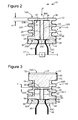
- a pressure-sensitive switch 10 may include a bellows element 12 having a closed end 12A and an open end 12C sealed with a seal plug 14.
- a side portion 12B connects the closed end 12A to the open end 12C.
- the side portion 12B may be manufactured to have one or more undulations as illustrated on Figure 2 .
- the side portion 12B of the bellows 12 may provide a precise spring rate so that the pressure at which the switch carries out its intended function can be well-predicted.
- the seal plug may be penetrated by an input signal lead 16 and by an output signal lead 18.
- the signal leads 16 and 18 are sealed so that air or other gas cannot enter or escape chamber 12D.
- the seal plug 14 may be positioned in abutting contact with a base plug 20 to hold the base plug captured in a recess 22 of the bellows element 12.
- the seal plug may be glued or fixed by other means to sides of the bellows 12.
- the seal plug may be glued or fixed by other means to the bottom part of the base plug.
- the base plug 20 may be made of an electrically-insulating material for reasons to be discussed later.
- the base plug 20 is a printed circuit board (PCB) that has electrical contacts on opposite faces 20A and 20B.
- a first input contact pad 24 is positioned between the seal plug 14 and the base plug 20, on face 20A of the base plug, for electrical contact with the input signal lead 16.
- a first output contact pad 26 is positioned between the seal plug and the base plug, on face 20A of the base plug, for electrical contact with the output signal lead 18.
- the first input contact pad communicates electrically with an input jumper 28 which terminates in a second input contact pad 30 on the face 20B.
- the first output contact pad 26 communicates electrically with an input jumper 32 which terminates in a second output contact pad 34 also on the face 20B.
- the two faces 20A and 20B may be opposite each other.
- the area of the face 20A, facing the seal plug 14, is larger than the area of the face 20B.
- the base plug 20 may have a T-shape, with the large part 20C facing the seal plug 14.
- Other shapes of the base plug may be possible.
- the narrow part 20D of the base plug 20 makes a clearance G with the side portion 12B of the bellows 12. This clearance accommodates the side portion 12B when a pressure P compresses the bellows 12 and the side portions 12B expand due to the compression.
- a size h of an undulation of the side portion 12B may be selected based on the strength of the material used for the bellows 12 and also on the desired depth at which the switch switches off the corresponding sensor S.
- Bellows 12 be made of an electrically-conductive material, e.g., a metal or other material. The number of undulations of the side portion 12B may vary, for example, between one and ten.
- the top surface 12A of the bellows 12 comprises an electrically-conductive surface 36, which may be substantially flat with a protuberance 36A as illustrated in the figure.
- the protuberance may be formed to contact the contact pads 30 and 34.
- the conductive surface 36 may be flat with no protuberances (e.g., smooth with no angle changes in its surface).
- the conductive surface 36 may have, besides a flat portion, dimples, other protuberances, or a non-flat profile to increase contact pressure.
- the dimples or other protuberances move integrally with the flat portion, i.e., the dimples or other protuberances cannot move relative to the flat portion as in the case of a corrugated surface.
- the inside of the bellows 12 and the outside of the base plug 20 form a chamber 12D.
- the chamber 12D may be hermetically closed, thus, encapsulating, for example, air at a desired pressure. Other gases than air may be used to fill chamber 12D.
- the bellows 12 When the pressure-sensitive switch 10 is exposed to atmospheric pressure, the bellows 12 is in its relaxed position, and the electrically-conductive surface 36 is not in electrical contact with the second input contact pad 30 and the second output contact pad 34.
- the bellows 12 becomes compressed, i.e., the size h of the undulation decreases and the gap H between the surface 36 and the face 20B of the base plug 20 also decreases.
- the gap H When the switch reaches a desired depth (e.g., 35 m), the gap H may become zero, i.e., the electrically-conductive surface 36 contacts the contact pads 30 and 34.
- the gap H between the conductive surface 36 and the top side 20B of the base plug is calculated based on a spring constant of the side portion 12B of the bellows 12 so that for a predetermined outside pressure (P), the gap H becomes zero.
- This action shorts the contact pads 30 and 34, thereby shorting across the seismic sensor S, e.g., hydrophone, which includes a signal line 17. Shorting across the hydrophone S effectively disables the hydrophone for that given depth.
- the switch opens sensor S and, thus, sensor S can be again used for seismic recording. In other words, the short lasts only as long as the external pressure is above the predetermined value.
- the switch 10 may be assembled in a hyperbaric chamber set at a predetermined pressure (that may correspond to the pressure exerted by a water column of 35 m). In this way, a selected pressure is captured within the bellows 12, which combined with the bellows spring constant, sets the hydrostatic pressure at which the switch will function to short the hydrophone. As the switch is assembled, a seal bead 38 may be formed around the seal plug 14, sealing in the predetermined pressure. In other words, the chamber 12D is hermetically sealed with the seal bead 38.
- the embodiment of Figure 2 includes, among others, the advantage that the bellows forms a unitary body to hold in the selected pressure, and a single, simple bead effectively seals the entire mechanism. This embodiment also provides the advantage of being able to withstand high overpressure conditions.
- FIG 3 depicts another embodiment of a switch 40.
- the switch 40 includes a bellows element 42 sealed at one end 42C with a seal plug 44 and at its other end 42A with an end plug 45.
- the bellows element 42 has a side portion 42B acting as a spring mechanism (e.g., corrugated or undulate portion) that provides a more precise spring rate than existing switches so that the pressure at which the switch carries out its intended function can be well-predicted.
- the seal plug is penetrated by an input signal lead 46 and by an output signal lead 48.
- the seal plug 44 is positioned in abutting contact with a base plug 50 to hold the base plug captured in a recess 52 of the bellows element 42.
- Both the base plug 50 and the end plug 45 may have a T-shape as illustrated in the figure. Of course, other shapes may be implemented as would be appreciated by those skilled in the art.
- the end plug may be made of any insulator material, while the base plug 50 may be made similar to the base plug 20 illustrated in Figure 2 .
- a first input contact pad 54 is positioned at an interface between the seal plug 44 and the base plug 50 (on a lower face 50A of the base plug 50) for electrical contact with the input signal lead 46.
- a first output contact pad 56 is positioned at the interface between the seal plug and the base plug (on an upper face 50B of the base plug 50) for electrical contact with the output signal lead 48.
- the first input contact pad communicates electrically with an input jumper 58 which terminates in a second input contact pad 60 on a top surface 50B of the base plug 50.
- the first output contact pad 56 communicates electrically with an input jumper 62 which terminates in a second output contact pad 64 also on the top surface of the base plug 50.
- the end plug 45 is sealed within an upper recess 70 of the bellows 42 with a seal bead 72.
- a top plate 73 may be located over the end plug 45.
- the top plate 73 may be made of a metallic material.
- An electrode (shorting contact) 74 may be located on the bottom surface of the end plug 45 to face the base plug 50.
- the electrode 74 may be entirely flat, or may have one or more protuberances to better contact corresponding pads.
- the bellows 42 When the pressure-sensitive switch 40 is exposed to atmospheric pressure, the bellows 42 is in its relaxed position and the shorting contact 74 is not in electrical contact with the second input contact pad 60 and the second output contact pad 64. However, when the switch 40 is submerged and, therefore, subjected to underwater hydrostatic pressure, the bellows 42 compresses until the shorting contact 74 contacts the contact pads 60 and 64 (i.e., gap H is reduced to zero). This shorts across the contact pads 60 and 64, thereby shorting across the hydrophone (not shown) and disabling it.
- the switch 40 is also preferably assembled in a hyperbaric chamber set at a predetermined pressure. This captures a selected pressure within the bellows 42, which automatically sets the hydrostatic pressure at which the switch will function to short the hydrophone. As the switch is assembled, a seal bead 68 is formed around the seal plug, sealing in the predetermined pressure, as well as the seal bead 72.
- the embodiment of Figure 3 includes, among others, the advantage that the bellows element of this embodiment is less expensive to produce and provides a more robust contact mating function.
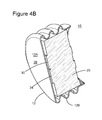
- FIG. 4A An overall view of either the switch 10 or the switch 40 is illustrated in Figure 4A , which shows the bellows 12, 42 configured to receive the base plug 20, 50.
- the pads 30, 34, 60, 64 are visible on the upper face of the plug.
- Figure 4B shows a cut-through (cross-section) of the switch 10.
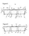
- Figure 5 depicts another embodiment of a pressure-sensitive switch 80.
- the switch comprises a shaped metal cap 82 with a radially outwardly extending bulge 84.
- the metal cap may be cylindrical, and the bulge (or hump) may extend all around the metal cap. In one application, there is a single bulge or hump.
- the cap includes a cylindrical body 91 defining a body diameter. Other shapes for the metal cap and body may be imagined, for example, oval, etc. Note that the bulge 84 has a diameter larger than the diameter of the cylindrical body 91.
- the bulge 84 serves as a spring mechanism supporting a top surface 86 of the cap 82, and the bulge extends radially beyond the body diameter.
- the top surface 86 Under pressure, the top surface 86 is pressed down, and the bulge 84 flexes inward so the top surface 86 moves toward a seal plug 88.
- the seal plug 88 is positioned within the cap 82 and sealed with a seal bead 90 so that a hermetically closed chamber 82A is formed between the cap 82 and the seal plug 88.
- a bottom input contact 92 is formed on the bottom of the seal plug 88, and the contact 92 is electrically coupled to an input jumper 94, which connects to an upper input contact 96.
- a bottom output contact 98 is formed on the bottom of the seal plug 88 and connects to an output jumper 100 and then to an upper output contact 102.
- the upper input and output contacts 96 and 102 are formed on a top surface 88A of the seal plug 88 and face the top surface 86.
- the contact 92 is connected to an input signal lead 104 and the contact 98 is connected to an output signal lead 106.
- the signal leads 104 and 106 are connected to a seismic sensor, for example, a hydrophone, similar to the embodiment illustrated in Figure 2 .
- the positioning of the seal plug 88 within the cap 82 determines the set point of the switch, because the vertical distance between the top surface 86 and the contacts 96 and 102 determines the distance the top surface 86 needs to travel to make contact.
- the embodiment of Figure 5 includes a set of downwardly projecting contact points 104 on the underside of the top surface 86. In one embodiment, there are three such contact points 104, to make contact with the contacts 96 and 102. Three contact points ensure balanced contact between the mating surfaces.
- the embodiment of Figure 6 is constructed in a similar fashion, but without the contact points, i.e., the top surface 86 is entirely flat (smooth).
- the optimum thickness of the top surface is about 0.15 mm, or about .006".
- the deflection (corresponding to gap H in Figures 2 and 3 ) for the structure illustrated in Figures 5 and 6 is about 0.38 mm, or about .015" to achieve desired switching pressure of 3.1 bar (45 psi), which corresponds to a depth of about 31 m.
- the present regulations require that the hydrophone is made inactive at about 35 m. In order to not exceed this depth, the present embodiment uses a depth of 31 m for short-circuiting the hydrophone. However, other depths may be used depending the regulations of each country.
- the switch can easily withstand an overpressure condition of 25 bar (362 psi), without exceeding yield strength anywhere in the switch, i.e., the switch is designed such that over pressuring the device will not increase its operational range.
- the top surface in any of the embodiments discussed above may be made of Beryllium Copper Alloy, although metals may also be used to reduce costs.
- FIG. 7 An overall view of the switch discussed above with regard to Figures 5 and 6 is shown in Figure 7 .
- the metal cap 82 is shown having the top surface 86 and the spring mechanism (bulge) 84. Note that this embodiment shows a single bulge 84. This has the advantage of easily being manufactured.
- the seal plug 88 is shown having two contacts 96 and 102 separated from each other and each communicating with corresponding jumpers 94 and 100, respectively.
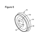
- the shape of the contacts 96 and 102 is shown to be semi-circular in Figure 7 . However, other shapes may be used as shown in Figure 8 .
- Figure 9 shows the inside of the metal cap 82 and the bottom surface of the seal plug 88, exposing the bottom input and output contacts 92 and 98.
- the seal plug 88 is shown made of two pieces 88A and 88B, e.g., one conductive and one non-conductive so that the signals to the output contacts 92 and 98 are separated from each other.
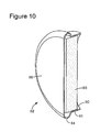
- Figure 10 shows a cross-section view of the switch 80.
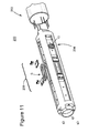
- FIG. 11 shows a hydrophone 200 that holds both elements S and the switch 10, for example, at a same location of the hydrophone carrier 206 inside the streamer.
- the hydrophone 200 illustrated in Figure 11 has four components S. However, a hydrophone may have fewer or more components.
- the switch may be implemented to control more than one sensor, e.g., a plurality of sensors. In one application, the switch is not provided next or in the same housing as the sensor.
- the sensor may be provided at a first location along the streamer and the switch may be provided at a second location, different from the first location, along the streamer.
- a method for switching off a seismic sensor when reaching a desired depth may be implemented as discussed next.
- the method includes a step 1200 of towing the seismic sensor at a predetermined water depth that is smaller than a threshold water depth, a step 1202 of recording seismic data with the seismic sensor, and a step 1204 of automatically switching off the seismic sensor with a switch located proximal to the seismic sensor, underwater, when a current depth of the seismic sensor is greater than the threshold water depth.
- the switch may be any of the switches discussed above.
- the disclosed exemplary embodiments provide a switch and a method for switching off (shorting) a seismic sensor when a predetermined depth in a marine environment is reached. It should be understood that this description is not intended to limit the invention. On the contrary, the exemplary embodiments are intended to cover alternatives, modifications, and equivalents, which are included in the spirit and scope of the invention as defined by the appended claims. Further, in the detailed description of the exemplary embodiments, numerous specific details are set forth to provide a comprehensive understanding of the claimed invention. However, one skilled in the art would understand that various embodiments may be practiced without such specific details.
Landscapes
- Physics & Mathematics (AREA)
- Fluid Mechanics (AREA)
- Life Sciences & Earth Sciences (AREA)
- General Life Sciences & Earth Sciences (AREA)
- Acoustics & Sound (AREA)
- Environmental & Geological Engineering (AREA)
- Geology (AREA)
- Remote Sensing (AREA)
- Engineering & Computer Science (AREA)
- General Physics & Mathematics (AREA)
- Geophysics (AREA)
- Measurement Of Mechanical Vibrations Or Ultrasonic Waves (AREA)
- Switches Operated By Changes In Physical Conditions (AREA)
- Geophysics And Detection Of Objects (AREA)
- Details Of Connecting Devices For Male And Female Coupling (AREA)
- Push-Button Switches (AREA)
Abstract
Description
- Embodiments of the subject matter disclosed herein generally relate to methods and systems and, more particularly, to mechanisms and techniques for automatically switching off seismic equipment used for marine geophysical exploration when a given depth is exceeded.
- Reflection seismology is a method of geophysical exploration to determine the properties of a portion of a subsurface layer in the earth, which information is especially helpful in the oil and gas industry. Marine reflection seismology is based on the use of a controlled seismic source that sends energy waves into the earth. By measuring the time it takes for the reflections to come back to plural receivers, it is possible to estimate the depth and/or composition of the features causing such reflections. These features may be associated with subterranean hydrocarbon deposits.
- For marine applications, a seismic source is towed by a vessel at a certain depth along direction X as illustrated in
Figure 1 . The acoustic waves from the seismic source (air gun, water gun, vibratory source, etc.) propagate in all directions.Figure 1 shows asource array 104 being towed behind avessel 101 at a shallow depth. Thesource array 104 may be connected to afloat 102 for floating at a given depth and also to thevessel 101 by an umbilical 111 for receiving, for example, electrical signals and/or compressed air. When the source array is activated, acoustic energy is coupled into the water and transmitted into the earth, where part of the energy is partially reflected back from theocean bottom 113 and from rock formation interfaces 112 (rock layer that has a change in acoustic impedance). Sensors orreceivers 106, located along astreamer 105, are used to record the reflected energy. Such receivers may include hydrophones, geophones and/or accelerometers. The receivers can be encapsulated in either fluid-filled orsolid streamers 105 that are also towed by vessels at shallow depth. - Currently, it is typical for one vessel to tow multiple streamers with diverters employed to ensure streamer separation by a fixed distance. In order to maintain the proper spacing between the streamers and sources, the vessel moves forward continuously, typically at a rate of about 4 knots (2 m/s). In some cases, the positions of the streamers can be controlled so that all receivers are at a common depth, or in other cases the receivers in each streamer are controlled to follow a particular depth profile.
- Modern streamers are equipped with birds, compasses and GPS receiver buoys. Birds are devices equipped with wings or fins, and the birds are spaced at intervals and are in communication with the vessel to control streamer depth and transverse spatial position. Alternatively, the receivers can be stationary and positioned on the ocean floor as autonomous nodes or in an ocean bottom cable.
- Depending upon the sensor type, the returning energy is recorded as a pressure, velocity or acceleration variation as a function of time at each receiver position. Combining recordings made at multiple source and receiver locations can be used to form an image of the subterranean features of the earth. Images formed from reflection seismology are useful for locating structures that are indicative of oil and/or gas reservoirs.
- However, the above-noted technology may be used not only for determining an image of the subsurface, but also objects present in the water, e.g., whales, dolphins, submarines, etc. Because of this dual use of the seismic acquisition systems, and in order to prevent commercial seismic systems to be used in the military field, there are national and international regulations requiring that each hydrophone be provided with a pressure-sensitive switch that switches off the hydrophone if it achieves a depth greater than 35 m.
- Effective design of such a pressure-sensitive switch to meet these requirements has not been easy. It is desirable that such a switch be inexpensive, particularly because seismic survey operations today use a number of streamers, each of which may have hundreds of hydrophones that must each have a depth-limiting device. The pressure at which the switch closes cannot deviate substantially from the desired depth setting, because the hydrophones operate in large arrays, and the premature disabling of some of the hydrophones can degrade the array's performance or even require suspension of a survey, at great expense.
-
De Groot et al., in U.S. Patent 6,318,497 , the entire content of which is incorporated herein by reference, discloses a pressure-sensitive switch including a base member having a mounting surface formed of electrically-insulating material. Two electrodes are mounted on the base member, with each electrode having an electrically-conductive contact surface. A flexible, corrugated diaphragm has its periphery secured in a fluid-tight manner to the mounting surface with its electrically-conductive central portion overlying the contact surfaces of the electrodes. The plural corrugations are exposed to the external pressure. When the switch is exposed to atmospheric pressure, the central portion of the diaphragm does not touch the contact surfaces of said electrodes, but when the switch is exposed to a pressure greater than the atmospheric pressure, this central portion is forced into contact with both contact surfaces, thus electrically connecting the two electrodes. - The switch disclosed by De Groot et al. has certain drawbacks. The corrugated diaphragm is unnecessarily complex, requiring a high degree of exacting quality control, which increases the cost of the entire unit. Also, the corrugated diaphragm must be very carefully set. Furthermore, slight variations in the configuration of the corrugated diaphragm result in the failure of the electrically-conductive elements of the switch to make contact.
- Thus, there remains a need for a simple, inexpensive, lightweight, pressure-sensitive switch for mounting in a hydrophone cable, and other applications, which eliminates the corrugated diaphragm. The present depth-limiting switch is directed to filling these and other needs in the art.
- According to one embodiment, there is a switch for a marine seismic sensor. The switch includes a bellows having a closed end, a closed side portion and an open end, wherein the side portion connects the closed end to the open end, the closed end includes a conductive surface, and the side portion acts as a spring; a base plug that includes first input and first output contacts on a first side and second input and second output contacts on an opposite side, wherein the first input contact is electrically connected to the second input contact through a first jumper and the first output contact is electrically connected to the second output contact through a second jumper; and a plug located in the open end of the bellows and configured to form a chamber inside which the second input contact and the second output contact are located, wherein the chamber is formed by the bellows and the base plug. The conductive surface short-circuits the second input contact and the second output contact when a pressure larger than a predetermined pressure (P) acts on the conductive surface.
- In this embodiment, the side portion of the bellows may be undulated.
- The side portion of the bellows may face a side portion of the base plug on which there are no electrical contacts.
- In a particular embodiment, the side portion of the bellows cannot contact the second input and output contacts.
- The conductive surface may be entirely flat.
- A gap H between the conductive surface and the second side of the base plug may for example be calculated based on a spring constant of the side portion so that when the predetermined pressure (P) acts on the conductive surface, the gap H is zero.
- The switch according to this embodiment may further include:
- an input signal lead electrically connected to the first input contact; and an output signal lead electrically connected to the first output contact, the input signal lead and the output signal lead being for example connected to a seismic sensor.
- The switch may further comprise a sealant covering a portion of the base plug and the bellows for sealing the chamber.
- According to another embodiment, there is a switch for a marine seismic sensor and the switch includes a bellows having a first open end, a side portion and a second open end, wherein the side portion connects the first open end to the second open end, and the side portion acts as a spring; a base plug located in the second open end and includes first input and first output contacts on a first side and second input and second output contacts on an opposite second side, wherein the first input contact is electrically connected to the second input contact through a first jumper and the first output contact is electrically connected to the second output contact through a second jumper; an end plug located in the first open end of the bellows and configured to include an electrode facing the second input contact and the second output contact; and a plug located in the open end of the bellows and configured to form a chamber with the bellows and the base plug, and the second input contact and the second output contact are located inside the chamber. The electrode short-circuits the second input contact and the second output contact when a pressure larger than a predetermined pressure (P) acts on the end plug.
- In this embodiment, the side portion of the bellows may be undulated.
- The side portion of the bellows faces for example a side portion of the base plug on which there are no electrical contacts.
- In a particular embodiment, the side portion of the bellows cannot contact the second input and output contacts.
- A gap H between the electrode and the second side of the base plug may for example be calculated based on a spring constant of the side portion of the bellows so that when the predetermined pressure (P) acts on the conductive surface, the gap H is zero.
- The switch may further comprise an input signal lead electrically connected to the first input contact and an output signal lead electrically connected to the first output contact, the input signal lead and the output signal lead being for example connected to a seismic sensor.
- According to still another embodiment, there is a switch for a marine seismic sensor that includes a metal cap having a spring region connecting a top surface to a body having an opening, wherein the spring region has a diameter larger than a diameter of the body; and a plug located inside the metal cap to close the opening and configured to host plural contacts. When a pressure is applied on the top surface, the spring region deforms to allow the top surface to move towards the plug, and when a predetermined pressure (P) is applied on the top surface, the spring region deforms to allow the top surface to contact two of the plural contacts.
- A corresponding seismic sensor may be shorted when two of the plural contacts are contacted by the top surface.
- The plural contacts may include first input and output contacts, second input and output contacts and jumpers that connect the first input contact to the second input contact and the first output contact to the second output contact.
- A side portion of the plug for example faces both the body and the spring region. The spring region may be a single hump.
- The metal cap may be cylindrical and the single hump may extend all around the metal cap.
- The switch may further comprise a sealant configured to hermetically insulate a chamber formed between the metal cap and the seal plug.
- The top surface is for example entirely flat.
- A center gap H between the top surface and the second side of the seal plug may for example be calculated based on a spring constant of the spring region so that when the predetermined pressure (P) acts on the top surface, the gap H is zero.
- The switch may further comprise an input signal lead electrically connected to the first input contact and an output signal lead electrically connected to the first output contact, the input signal lead and the output signal lead being connected for example to a seismic sensor.
- According to another embodiment, there is a method for switching off a seismic sensor during a marine seismic survey. The method includes towing the seismic sensor at a predetermined water depth that is smaller than a threshold water depth; recording seismic data with the seismic sensor; and automatically switching off the seismic sensor with a switch located proximal to the seismic sensor, under water, when a current depth of the seismic sensor is larger than the threshold water depth. The switch has a bellows and a conductive portion and the conductive portion is calibrated to touch two contact pads to switch off the seismic sensor when water pressure acts on the bellow at a depth larger than the threshold water depth.
- The accompanying drawings, which are incorporated in and constitute a part of the specification, illustrate one or more embodiments and, together with the description, explain these embodiments. In the drawings:
-
Figure 1 illustrates a traditional marine seismic survey system; -
Figure 2 is a schematic diagram of a switch according to an exemplary embodiment; -
Figure 3 is a schematic diagram of a switch according to another exemplary embodiment; -
Figure 4A is an overall view of the switch ofFigure 2 or 3 according to an exemplary embodiment; -
Figure 4B is a cross-section of the switch ofFigure 2 according to an exemplary embodiment; -
Figure 5 is a schematic diagram of another switch according to an exemplary embodiment; -
Figure 6 is a schematic diagram of still another switch according to an exemplary embodiment; -
Figure 7 is an overall view of the switches illustrated inFigures 5 or 6 according to an exemplary embodiment; -
Figure 8 is a back view of one of the switches illustrated inFigures 5 or 6 according to an exemplary embodiment; -
Figure 9 is another overall view of one of the switches illustrated inFigures 5 or 6 according to an exemplary embodiment; -
Figure 10 is a cross-section of one of the switches illustrated inFigures 5 or 6 according to an exemplary embodiment; -
Figure 11 is a schematic diagram of a sensor holder and the disposition of a switch relative to a seismic sensor according to an exemplary embodiment; and -
Figure 12 is a flowchart of a method for switching a seismic sensor with a switch according to an exemplary embodiment. - The following description of the exemplary embodiments refers to the accompanying drawings. The same reference numbers in different drawings identify the same or similar elements. The following detailed description does not limit the invention. Instead, the scope of the invention is defined by the appended claims. The following embodiments are discussed, for simplicity, with regard to a switch attached to a hydrophone and activated by pressure. However, the switches to be discussed next are not limited to a seismic environment, but may be applied to other structures that must be switched off automatically at a certain pressure.
- Reference throughout the specification to "one embodiment" or "an embodiment" means that a particular feature, structure, or characteristic described in connection with an embodiment is included in at least one embodiment of the subject matter disclosed. Thus, the appearance of the phrases "in one embodiment" or "in an embodiment" in various places throughout the specification is not necessarily referring to the same embodiment. Further, the particular features, structures, or characteristics may be combined in any suitable manner in one or more embodiments.
- According to an exemplary embodiment illustrated in
Figure 2 , a pressure-sensitive switch 10 may include abellows element 12 having aclosed end 12A and anopen end 12C sealed with a seal plug 14. Aside portion 12B connects theclosed end 12A to theopen end 12C. Theside portion 12B may be manufactured to have one or more undulations as illustrated onFigure 2 . Theside portion 12B of thebellows 12 may provide a precise spring rate so that the pressure at which the switch carries out its intended function can be well-predicted. The seal plug may be penetrated by aninput signal lead 16 and by anoutput signal lead 18. The signal leads 16 and 18 are sealed so that air or other gas cannot enter or escapechamber 12D. The seal plug 14 may be positioned in abutting contact with abase plug 20 to hold the base plug captured in arecess 22 of thebellows element 12. The seal plug may be glued or fixed by other means to sides of thebellows 12. Optionally, the seal plug may be glued or fixed by other means to the bottom part of the base plug. - The
base plug 20 may be made of an electrically-insulating material for reasons to be discussed later. In one embodiment, thebase plug 20 is a printed circuit board (PCB) that has electrical contacts onopposite faces input contact pad 24 is positioned between the seal plug 14 and thebase plug 20, onface 20A of the base plug, for electrical contact with theinput signal lead 16. Similarly, a firstoutput contact pad 26 is positioned between the seal plug and the base plug, onface 20A of the base plug, for electrical contact with theoutput signal lead 18. The first input contact pad communicates electrically with aninput jumper 28 which terminates in a secondinput contact pad 30 on theface 20B. The firstoutput contact pad 26 communicates electrically with aninput jumper 32 which terminates in a secondoutput contact pad 34 also on theface 20B. The two faces 20A and 20B may be opposite each other. - In one embodiment, the area of the
face 20A, facing the seal plug 14, is larger than the area of theface 20B. For example, as illustrated inFigure 2 , thebase plug 20 may have a T-shape, with thelarge part 20C facing the seal plug 14. Other shapes of the base plug may be possible. Thenarrow part 20D of thebase plug 20 makes a clearance G with theside portion 12B of thebellows 12. This clearance accommodates theside portion 12B when a pressure P compresses thebellows 12 and theside portions 12B expand due to the compression. A size h of an undulation of theside portion 12B may be selected based on the strength of the material used for thebellows 12 and also on the desired depth at which the switch switches off the corresponding sensor S. Bellows 12 be made of an electrically-conductive material, e.g., a metal or other material. The number of undulations of theside portion 12B may vary, for example, between one and ten. - The
top surface 12A of thebellows 12 comprises an electrically-conductive surface 36, which may be substantially flat with aprotuberance 36A as illustrated in the figure. The protuberance may be formed to contact thecontact pads conductive surface 36 may be flat with no protuberances (e.g., smooth with no angle changes in its surface). However, as illustrated later, theconductive surface 36 may have, besides a flat portion, dimples, other protuberances, or a non-flat profile to increase contact pressure. When functional, the dimples or other protuberances move integrally with the flat portion, i.e., the dimples or other protuberances cannot move relative to the flat portion as in the case of a corrugated surface. The inside of thebellows 12 and the outside of thebase plug 20 form achamber 12D. As discussed later, thechamber 12D may be hermetically closed, thus, encapsulating, for example, air at a desired pressure. Other gases than air may be used to fillchamber 12D. - When the pressure-
sensitive switch 10 is exposed to atmospheric pressure, thebellows 12 is in its relaxed position, and the electrically-conductive surface 36 is not in electrical contact with the secondinput contact pad 30 and the secondoutput contact pad 34. When theswitch 10 is submerged underwater and, therefore, subjected to underwater hydrostatic pressure, thebellows 12 becomes compressed, i.e., the size h of the undulation decreases and the gap H between thesurface 36 and theface 20B of thebase plug 20 also decreases. When the switch reaches a desired depth (e.g., 35 m), the gap H may become zero, i.e., the electrically-conductive surface 36 contacts thecontact pads conductive surface 36 and thetop side 20B of the base plug is calculated based on a spring constant of theside portion 12B of thebellows 12 so that for a predetermined outside pressure (P), the gap H becomes zero. This action shorts thecontact pads signal line 17. Shorting across the hydrophone S effectively disables the hydrophone for that given depth. However, when the streamer moves above the shorting depth, the switch opens sensor S and, thus, sensor S can be again used for seismic recording. In other words, the short lasts only as long as the external pressure is above the predetermined value. - The
switch 10 may be assembled in a hyperbaric chamber set at a predetermined pressure (that may correspond to the pressure exerted by a water column of 35 m). In this way, a selected pressure is captured within thebellows 12, which combined with the bellows spring constant, sets the hydrostatic pressure at which the switch will function to short the hydrophone. As the switch is assembled, aseal bead 38 may be formed around the seal plug 14, sealing in the predetermined pressure. In other words, thechamber 12D is hermetically sealed with theseal bead 38. Thus, the embodiment ofFigure 2 includes, among others, the advantage that the bellows forms a unitary body to hold in the selected pressure, and a single, simple bead effectively seals the entire mechanism. This embodiment also provides the advantage of being able to withstand high overpressure conditions. -
Figure 3 depicts another embodiment of aswitch 40. Theswitch 40 includes abellows element 42 sealed at oneend 42C with aseal plug 44 and at itsother end 42A with anend plug 45. As for the device ofFigure 2 , thebellows element 42 has aside portion 42B acting as a spring mechanism (e.g., corrugated or undulate portion) that provides a more precise spring rate than existing switches so that the pressure at which the switch carries out its intended function can be well-predicted. The seal plug is penetrated by aninput signal lead 46 and by anoutput signal lead 48. The seal plug 44 is positioned in abutting contact with abase plug 50 to hold the base plug captured in arecess 52 of thebellows element 42. Both thebase plug 50 and theend plug 45 may have a T-shape as illustrated in the figure. Of course, other shapes may be implemented as would be appreciated by those skilled in the art. The end plug may be made of any insulator material, while thebase plug 50 may be made similar to thebase plug 20 illustrated inFigure 2 . - A first
input contact pad 54 is positioned at an interface between theseal plug 44 and the base plug 50 (on alower face 50A of the base plug 50) for electrical contact with theinput signal lead 46. Similarly, a firstoutput contact pad 56 is positioned at the interface between the seal plug and the base plug (on anupper face 50B of the base plug 50) for electrical contact with theoutput signal lead 48. The first input contact pad communicates electrically with aninput jumper 58 which terminates in a secondinput contact pad 60 on atop surface 50B of thebase plug 50. The firstoutput contact pad 56 communicates electrically with aninput jumper 62 which terminates in a secondoutput contact pad 64 also on the top surface of thebase plug 50. - The end plug 45 is sealed within an
upper recess 70 of thebellows 42 with aseal bead 72. Optionally, atop plate 73 may be located over theend plug 45. Thetop plate 73 may be made of a metallic material. An electrode (shorting contact) 74 may be located on the bottom surface of theend plug 45 to face thebase plug 50. Theelectrode 74 may be entirely flat, or may have one or more protuberances to better contact corresponding pads. - When the pressure-
sensitive switch 40 is exposed to atmospheric pressure, thebellows 42 is in its relaxed position and the shortingcontact 74 is not in electrical contact with the secondinput contact pad 60 and the secondoutput contact pad 64. However, when theswitch 40 is submerged and, therefore, subjected to underwater hydrostatic pressure, thebellows 42 compresses until the shortingcontact 74 contacts thecontact pads 60 and 64 (i.e., gap H is reduced to zero). This shorts across thecontact pads - The
switch 40 is also preferably assembled in a hyperbaric chamber set at a predetermined pressure. This captures a selected pressure within thebellows 42, which automatically sets the hydrostatic pressure at which the switch will function to short the hydrophone. As the switch is assembled, aseal bead 68 is formed around the seal plug, sealing in the predetermined pressure, as well as theseal bead 72. The embodiment ofFigure 3 includes, among others, the advantage that the bellows element of this embodiment is less expensive to produce and provides a more robust contact mating function. - An overall view of either the
switch 10 or theswitch 40 is illustrated inFigure 4A , which shows thebellows base plug pads Figure 4B shows a cut-through (cross-section) of theswitch 10. -
Figure 5 depicts another embodiment of a pressure-sensitive switch 80. The switch comprises a shapedmetal cap 82 with a radially outwardly extendingbulge 84. The metal cap may be cylindrical, and the bulge (or hump) may extend all around the metal cap. In one application, there is a single bulge or hump. The cap includes acylindrical body 91 defining a body diameter. Other shapes for the metal cap and body may be imagined, for example, oval, etc. Note that thebulge 84 has a diameter larger than the diameter of thecylindrical body 91. Thebulge 84 serves as a spring mechanism supporting atop surface 86 of thecap 82, and the bulge extends radially beyond the body diameter. Under pressure, thetop surface 86 is pressed down, and thebulge 84 flexes inward so thetop surface 86 moves toward aseal plug 88. The seal plug 88 is positioned within thecap 82 and sealed with aseal bead 90 so that a hermeticallyclosed chamber 82A is formed between thecap 82 and theseal plug 88. Abottom input contact 92 is formed on the bottom of theseal plug 88, and thecontact 92 is electrically coupled to aninput jumper 94, which connects to anupper input contact 96. Similarly, abottom output contact 98 is formed on the bottom of theseal plug 88 and connects to anoutput jumper 100 and then to anupper output contact 102. The upper input andoutput contacts top surface 88A of theseal plug 88 and face thetop surface 86. Thecontact 92 is connected to aninput signal lead 104 and thecontact 98 is connected to anoutput signal lead 106. The signal leads 104 and 106 are connected to a seismic sensor, for example, a hydrophone, similar to the embodiment illustrated inFigure 2 . - The positioning of the
seal plug 88 within thecap 82 determines the set point of the switch, because the vertical distance between thetop surface 86 and thecontacts top surface 86 needs to travel to make contact. The embodiment ofFigure 5 includes a set of downwardly projecting contact points 104 on the underside of thetop surface 86. In one embodiment, there are three such contact points 104, to make contact with thecontacts Figure 6 is constructed in a similar fashion, but without the contact points, i.e., thetop surface 86 is entirely flat (smooth). - Analysis has shown that the optimum thickness of the top surface is about 0.15 mm, or about .006". The deflection (corresponding to gap H in
Figures 2 and 3 ) for the structure illustrated inFigures 5 and 6 is about 0.38 mm, or about .015" to achieve desired switching pressure of 3.1 bar (45 psi), which corresponds to a depth of about 31 m. It is noted that the present regulations require that the hydrophone is made inactive at about 35 m. In order to not exceed this depth, the present embodiment uses a depth of 31 m for short-circuiting the hydrophone. However, other depths may be used depending the regulations of each country. The switch can easily withstand an overpressure condition of 25 bar (362 psi), without exceeding yield strength anywhere in the switch, i.e., the switch is designed such that over pressuring the device will not increase its operational range. The top surface in any of the embodiments discussed above may be made of Beryllium Copper Alloy, although metals may also be used to reduce costs. - An overall view of the switch discussed above with regard to
Figures 5 and 6 is shown inFigure 7 . Themetal cap 82 is shown having thetop surface 86 and the spring mechanism (bulge) 84. Note that this embodiment shows asingle bulge 84. This has the advantage of easily being manufactured. The seal plug 88 is shown having twocontacts jumpers contacts Figure 7 . However, other shapes may be used as shown inFigure 8 .Figure 9 shows the inside of themetal cap 82 and the bottom surface of theseal plug 88, exposing the bottom input andoutput contacts pieces 88A and 88B, e.g., one conductive and one non-conductive so that the signals to theoutput contacts Figure 10 shows a cross-section view of theswitch 80. - The switches discussed above may be internal to the hydrophone in a location so they cannot be easily defeated or removed. For example,
Figure 11 shows ahydrophone 200 that holds both elements S and theswitch 10, for example, at a same location of thehydrophone carrier 206 inside the streamer. Thehydrophone 200 illustrated inFigure 11 has four components S. However, a hydrophone may have fewer or more components. Further, the switch may be implemented to control more than one sensor, e.g., a plurality of sensors. In one application, the switch is not provided next or in the same housing as the sensor. For example, the sensor may be provided at a first location along the streamer and the switch may be provided at a second location, different from the first location, along the streamer. - A method for switching off a seismic sensor when reaching a desired depth may be implemented as discussed next. As illustrated in
Figure 12 , the method includes astep 1200 of towing the seismic sensor at a predetermined water depth that is smaller than a threshold water depth, astep 1202 of recording seismic data with the seismic sensor, and astep 1204 of automatically switching off the seismic sensor with a switch located proximal to the seismic sensor, underwater, when a current depth of the seismic sensor is greater than the threshold water depth. The switch may be any of the switches discussed above. - The disclosed exemplary embodiments provide a switch and a method for switching off (shorting) a seismic sensor when a predetermined depth in a marine environment is reached. It should be understood that this description is not intended to limit the invention. On the contrary, the exemplary embodiments are intended to cover alternatives, modifications, and equivalents, which are included in the spirit and scope of the invention as defined by the appended claims. Further, in the detailed description of the exemplary embodiments, numerous specific details are set forth to provide a comprehensive understanding of the claimed invention. However, one skilled in the art would understand that various embodiments may be practiced without such specific details.
- Although the features and elements of the present exemplary embodiments are described in the embodiments in particular combinations, each feature or element can be used alone, without the other features and elements of the embodiments, or in various combinations with or without other features and elements disclosed herein.
- This written description uses examples of the subject matter disclosed to enable any person skilled in the art to practice the same, including making and using any devices or systems and performing any incorporated methods. The patentable scope of the subject matter is defined by the claims, and may include other examples that occur to those skilled in the art. Such other examples are intended to be within the scope of the claims.
Claims (18)
- A switch for a marine seismic sensor, the switch comprising:a bellows having a closed end, a closed side portion and an open end, wherein the side portion connects the closed end to the open end, the closed end includes a conductive surface, and the side portion acts as a spring;a base plug that includes first input and first output contacts on a first side and second input and second output contacts on an opposite side, wherein the first input contact is electrically connected to the second input contact through a first jumper and the first output contact is electrically connected to the second output contact through a second jumper; anda plug located in the open end of the bellows and configured to form a chamber inside which the second input contact and the second output contact are located, wherein the chamber is formed by the bellows and the base plug,wherein the conductive surface short-circuits the second input contact and the second output contact when a pressure larger than a predetermined pressure (P) acts on the conductive surface.
- The switch of Claim 1, wherein the conductive surface is entirely flat.
- The switch of Claim 1, wherein a gap H between the conductive surface and the second side of the base plug is calculated based on a spring constant of the side portion so that when the predetermined pressure (P) acts on the conductive surface, the gap H is zero.
- The switch of Claim 1, further comprising:an input signal lead electrically connected to the first input contact; andan output signal lead electrically connected to the first output contact,wherein the input signal lead and the output signal lead are connected to a seismic sensor.
- A switch for a marine seismic sensor, the switch comprising:a bellows having a first open end, a side portion and a second open end, wherein the side portion connects the first open end to the second open end, and the side portion acts as a spring;a base plug located in the second open end and includes first input and first output contacts on a first side and second input and second output contacts on an opposite second side, wherein the first input contact is electrically connected to the second input contact through a first jumper and the first output contact is electrically connected to the second output contact through a second jumper;an end plug located in the first open end of the bellows and configured to include an electrode facing the second input contact and the second output contact; anda plug located in the open end of the bellows and configured to form a chamber with the bellows and the base plug, and the second input contact and the second output contact are located inside the chamber,wherein the electrode short-circuits the second input contact and the second output contact when a pressure larger than a predetermined pressure (P) acts on the end plug.
- The switch of Claim 1 or 5, wherein the side portion of the bellows is undulated.
- The switch of Claim 1 or 5, wherein the side portion of the bellows faces a side portion of the base plug on which there are no electrical contacts.
- The switch of Claim 1 or 5, wherein the side portion of the bellows cannot contact the second input and output contacts.
- The switch of Claim 5, wherein a gap H between the electrode and the second side of the base plug is calculated based on a spring constant of the side portion of the bellows so that when the predetermined pressure (P) acts on the conductive surface, the gap H is zero.
- A switch for a marine seismic sensor, the switch comprising:a metal cap having a spring region connecting a top surface to a body having an opening, wherein the spring region has a diameter larger than a diameter of the body; anda plug located inside the metal cap to close the opening and configured to host plural contacts,wherein when a pressure is applied on the top surface, the spring region deforms to allow the top surface to move towards the plug; andwhen a predetermined pressure (P) is applied on the top surface, the spring region deforms to allow the top surface to contact two of the plural contacts.
- The switch of Claim 10, wherein a corresponding seismic sensor is shorted when two of the plural contacts are contacted by the top surface.
- The switch of Claim 10, wherein the plural contacts include first input and output contacts, second input and output contacts and jumpers that connect the first input contact to the second input contact and the first output contact to the second output contact.
- The switch of Claim 10, wherein a side portion of the plug faces both the body and the spring region.
- The switch of Claim 10, wherein the spring region is a single hump and wherein the metal cap is cylindrical and the single hump extends all around the metal cap.
- The switch of Claim 10, wherein the top surface is entirely flat.
- The switch of Claim 10, wherein a center gap H between the top surface and the second side of the seal plug is calculated based on a spring constant of the spring region so that when the predetermined pressure (P) acts on the top surface, the gap H is zero.
- The switch of Claim 1, 5 or 10, further comprising:an input signal lead electrically connected to the first input contact; andan output signal lead electrically connected to the first output contact,wherein the input signal lead and the output signal lead are connected to a seismic sensor.
- A method for switching off a seismic sensor during a marine seismic survey, the method comprising:towing the seismic sensor at a predetermined water depth that is smaller than a threshold water depth;recording seismic data with the seismic sensor; andautomatically switching off the seismic sensor with a switch located proximal to the seismic sensor, under water, when a current depth of the seismic sensor is larger than the threshold water depth,wherein the switch has a bellows and a conductive portion and the conductive portion is calibrated to touch two contact pads to switch off the seismic sensor when water pressure acts on the bellow at a depth larger than the threshold water depth.
Priority Applications (5)
| Application Number | Priority Date | Filing Date | Title |
|---|---|---|---|
| CA 2848496 CA2848496A1 (en) | 2013-04-19 | 2014-04-04 | Depth-activated sensor switch and method |
| MX2014004608A MX336060B (en) | 2013-04-19 | 2014-04-15 | Depth-activated sensor switch and method. |
| BRBR102014009380-0A BR102014009380A2 (en) | 2013-04-19 | 2014-04-17 | DEPTH SENSOR SWITCH ACTIVATED AND METHOD |
| RU2014115792A RU2645427C2 (en) | 2013-04-19 | 2014-04-18 | Depth-activated sensor switch and method of switching it off |
| CN201410157866.3A CN104112624B (en) | 2013-04-19 | 2014-04-18 | By the sensing switch and method of deep activation |
Applications Claiming Priority (1)
| Application Number | Priority Date | Filing Date | Title |
|---|---|---|---|
| US13/866,161 US9251983B2 (en) | 2013-04-19 | 2013-04-19 | Depth-activated sensor switch and method |
Publications (3)
| Publication Number | Publication Date |
|---|---|
| EP2793057A2 true EP2793057A2 (en) | 2014-10-22 |
| EP2793057A3 EP2793057A3 (en) | 2017-03-01 |
| EP2793057B1 EP2793057B1 (en) | 2018-05-30 |
Family
ID=49918488
Family Applications (1)
| Application Number | Title | Priority Date | Filing Date |
|---|---|---|---|
| EP13199905.4A Not-in-force EP2793057B1 (en) | 2013-04-19 | 2013-12-31 | Depth-Activated Sensor Switch and Method |
Country Status (7)
| Country | Link |
|---|---|
| US (1) | US9251983B2 (en) |
| EP (1) | EP2793057B1 (en) |
| CN (1) | CN104112624B (en) |
| BR (1) | BR102014009380A2 (en) |
| CA (1) | CA2848496A1 (en) |
| MX (1) | MX336060B (en) |
| RU (1) | RU2645427C2 (en) |
Families Citing this family (4)
| Publication number | Priority date | Publication date | Assignee | Title |
|---|---|---|---|---|
| ITUB20169980A1 (en) * | 2016-01-14 | 2017-07-14 | Saipem Spa | UNDERWATER CONTROL DEVICE AND CONTROL SYSTEM FOR A DIVING PRODUCTION SYSTEM OF HYDROCARBONS |
| US10763143B2 (en) * | 2017-08-18 | 2020-09-01 | Applied Materials, Inc. | Processing tool having a monitoring device |
| AT521702B1 (en) * | 2019-03-11 | 2020-04-15 | Piezocryst Advanced Sensorics | MEASURING SYSTEM, SUITABLE FOR INSTALLATION BETWEEN TORQUE AND / OR FORCE TRANSMISSION MACHINE PARTS |
| CN113309925A (en) * | 2021-06-30 | 2021-08-27 | 许昌德力科电子机械科技有限公司 | Hydraulic shock absorber |
Family Cites Families (13)
| Publication number | Priority date | Publication date | Assignee | Title |
|---|---|---|---|---|
| US3496526A (en) * | 1968-11-19 | 1970-02-17 | Gulf General Atomic Inc | Seismic cable depth control system |
| US3909774A (en) * | 1974-07-25 | 1975-09-30 | Whitehall Corp | Controlled buoyancy system for seismic streamer sections |
| US4455500A (en) | 1983-07-28 | 1984-06-19 | Western Geophysical Company Of America | Sensitivity and capacitance adjustment method for piezoelectric accelerometers |
| JP2593213B2 (en) * | 1988-12-17 | 1997-03-26 | 株式会社ブリヂストン | pressure switch |
| US5379267A (en) * | 1992-02-11 | 1995-01-03 | Sparton Corporation | Buoyancy control system |
| JP2893622B2 (en) * | 1992-04-03 | 1999-05-24 | 矢崎総業株式会社 | Pressure switch and gas meter |
| GB9713973D0 (en) * | 1997-07-03 | 1997-09-10 | Secr Defence | Depth control device |
| US6049511A (en) * | 1999-05-07 | 2000-04-11 | Geosensor Corporation | High sensitivity fiber optic hydrophone |
| US6318497B1 (en) | 2000-02-29 | 2001-11-20 | Benthos, Inc. | Pressure-sensitive switch, its method of calibration and use in a hydrophone array |
| FR2832019B1 (en) * | 2001-11-02 | 2004-01-02 | Inst Francais Du Petrole | HYDROPHONE WITH AUTOMATIC INHIBITION IN CASE OF EXCEEDING AN ADJUSTABLE IMMERSION THRESHOLD |
| FR2888339B1 (en) * | 2005-07-07 | 2007-09-21 | Sercel Sa | OPTICAL FIBER SEISMIC SENSOR |
| US7570543B2 (en) * | 2005-09-09 | 2009-08-04 | Teledyne Benthos, Inc. | Normally closed pressure-sensitive hydrophone switch |
| US8995220B2 (en) * | 2010-01-28 | 2015-03-31 | Pgs Geophysical As | Method and system for streamer depth control |
-
2013
- 2013-04-19 US US13/866,161 patent/US9251983B2/en active Active
- 2013-12-31 EP EP13199905.4A patent/EP2793057B1/en not_active Not-in-force
-
2014
- 2014-04-04 CA CA 2848496 patent/CA2848496A1/en not_active Abandoned
- 2014-04-15 MX MX2014004608A patent/MX336060B/en unknown
- 2014-04-17 BR BRBR102014009380-0A patent/BR102014009380A2/en not_active Application Discontinuation
- 2014-04-18 CN CN201410157866.3A patent/CN104112624B/en not_active Expired - Fee Related
- 2014-04-18 RU RU2014115792A patent/RU2645427C2/en not_active IP Right Cessation
Also Published As
| Publication number | Publication date |
|---|---|
| US9251983B2 (en) | 2016-02-02 |
| CN104112624A (en) | 2014-10-22 |
| US20140312713A1 (en) | 2014-10-23 |
| CN104112624B (en) | 2018-08-14 |
| MX336060B (en) | 2016-01-07 |
| MX2014004608A (en) | 2014-10-21 |
| EP2793057B1 (en) | 2018-05-30 |
| RU2645427C2 (en) | 2018-02-21 |
| RU2014115792A (en) | 2015-10-27 |
| CA2848496A1 (en) | 2014-10-19 |
| EP2793057A3 (en) | 2017-03-01 |
| BR102014009380A2 (en) | 2015-01-06 |
Similar Documents
| Publication | Publication Date | Title |
|---|---|---|
| US4345473A (en) | Vertical component accelerometer | |
| US4536862A (en) | Seismic cable assembly having improved transducers | |
| EP2793057B1 (en) | Depth-Activated Sensor Switch and Method | |
| US4942557A (en) | Marine seismic system | |
| CA1080342A (en) | Receiving seismic waves with an accelerometer and a hydrophone | |
| US3283293A (en) | Particle velocity detector and means for canceling the effects of motional disturbances applied thereto | |
| US3970878A (en) | Piezoelectric transducer unit and hydrophone assembly | |
| US9709687B2 (en) | Sensor assembly | |
| KR101563536B1 (en) | Low noise piezoceramic cylinder hydrophone for ocean bottom seismology and OBS receiver having the same | |
| CA2401008C (en) | Pressure-sensitive switch, its method of calibration and use in a hydrophone array | |
| CN104614066B (en) | A kind of piezoelectric ceramic hydrophone of metal shell sealing | |
| US5475652A (en) | Dual gimbal geophone | |
| US4015233A (en) | Pressure sensor of low sensitivity with respect to acceleration | |
| US11889760B2 (en) | Seismic pressure and acceleration sensor | |
| US7570543B2 (en) | Normally closed pressure-sensitive hydrophone switch | |
| CN1418040A (en) | Hydrophone with automatic supression function beyond the adjustable immersion threshold | |
| US20250267399A1 (en) | Low Cross Feed Hydrophone and Method of Manufacture | |
| NL2013968B1 (en) | Pressure tolerant seismic source. |
Legal Events
| Date | Code | Title | Description |
|---|---|---|---|
| PUAI | Public reference made under article 153(3) epc to a published international application that has entered the european phase |
Free format text: ORIGINAL CODE: 0009012 |
|
| 17P | Request for examination filed |
Effective date: 20131231 |
|
| AK | Designated contracting states |
Kind code of ref document: A2 Designated state(s): AL AT BE BG CH CY CZ DE DK EE ES FI FR GB GR HR HU IE IS IT LI LT LU LV MC MK MT NL NO PL PT RO RS SE SI SK SM TR |
|
| AX | Request for extension of the european patent |
Extension state: BA ME |
|
| PUAL | Search report despatched |
Free format text: ORIGINAL CODE: 0009013 |
|
| AK | Designated contracting states |
Kind code of ref document: A3 Designated state(s): AL AT BE BG CH CY CZ DE DK EE ES FI FR GB GR HR HU IE IS IT LI LT LU LV MC MK MT NL NO PL PT RO RS SE SI SK SM TR |
|
| AX | Request for extension of the european patent |
Extension state: BA ME |
|
| RIC1 | Information provided on ipc code assigned before grant |
Ipc: G01V 1/20 20060101AFI20170120BHEP Ipc: G01V 1/38 20060101ALN20170120BHEP Ipc: H01H 35/34 20060101ALI20170120BHEP |
|
| R17P | Request for examination filed (corrected) |
Effective date: 20170725 |
|
| RBV | Designated contracting states (corrected) |
Designated state(s): AL AT BE BG CH CY CZ DE DK EE ES FI FR GB GR HR HU IE IS IT LI LT LU LV MC MK MT NL NO PL PT RO RS SE SI SK SM TR |
|
| GRAP | Despatch of communication of intention to grant a patent |
Free format text: ORIGINAL CODE: EPIDOSNIGR1 |
|
| RIC1 | Information provided on ipc code assigned before grant |
Ipc: G01V 1/20 20060101AFI20180130BHEP Ipc: H01H 35/34 20060101ALI20180130BHEP Ipc: H01H 35/32 20060101ALI20180130BHEP Ipc: G01V 1/38 20060101ALN20180130BHEP |
|
| INTG | Intention to grant announced |
Effective date: 20180216 |
|
| GRAS | Grant fee paid |
Free format text: ORIGINAL CODE: EPIDOSNIGR3 |
|
| GRAA | (expected) grant |
Free format text: ORIGINAL CODE: 0009210 |
|
| AK | Designated contracting states |
Kind code of ref document: B1 Designated state(s): AL AT BE BG CH CY CZ DE DK EE ES FI FR GB GR HR HU IE IS IT LI LT LU LV MC MK MT NL NO PL PT RO RS SE SI SK SM TR |
|
| REG | Reference to a national code |
Ref country code: GB Ref legal event code: FG4D |
|
| REG | Reference to a national code |
Ref country code: CH Ref legal event code: EP |
|
| REG | Reference to a national code |
Ref country code: AT Ref legal event code: REF Ref document number: 1004185 Country of ref document: AT Kind code of ref document: T Effective date: 20180615 |
|
| REG | Reference to a national code |
Ref country code: IE Ref legal event code: FG4D |
|
| REG | Reference to a national code |
Ref country code: DE Ref legal event code: R096 Ref document number: 602013038087 Country of ref document: DE |
|
| REG | Reference to a national code |
Ref country code: NL Ref legal event code: FP |
|
| REG | Reference to a national code |
Ref country code: LT Ref legal event code: MG4D |
|
| REG | Reference to a national code |
Ref country code: NO Ref legal event code: T2 Effective date: 20180530 |
|
| PG25 | Lapsed in a contracting state [announced via postgrant information from national office to epo] |
Ref country code: CY Free format text: LAPSE BECAUSE OF FAILURE TO SUBMIT A TRANSLATION OF THE DESCRIPTION OR TO PAY THE FEE WITHIN THE PRESCRIBED TIME-LIMIT Effective date: 20180530 Ref country code: LT Free format text: LAPSE BECAUSE OF FAILURE TO SUBMIT A TRANSLATION OF THE DESCRIPTION OR TO PAY THE FEE WITHIN THE PRESCRIBED TIME-LIMIT Effective date: 20180530 Ref country code: SE Free format text: LAPSE BECAUSE OF FAILURE TO SUBMIT A TRANSLATION OF THE DESCRIPTION OR TO PAY THE FEE WITHIN THE PRESCRIBED TIME-LIMIT Effective date: 20180530 Ref country code: ES Free format text: LAPSE BECAUSE OF FAILURE TO SUBMIT A TRANSLATION OF THE DESCRIPTION OR TO PAY THE FEE WITHIN THE PRESCRIBED TIME-LIMIT Effective date: 20180530 Ref country code: BG Free format text: LAPSE BECAUSE OF FAILURE TO SUBMIT A TRANSLATION OF THE DESCRIPTION OR TO PAY THE FEE WITHIN THE PRESCRIBED TIME-LIMIT Effective date: 20180830 Ref country code: FI Free format text: LAPSE BECAUSE OF FAILURE TO SUBMIT A TRANSLATION OF THE DESCRIPTION OR TO PAY THE FEE WITHIN THE PRESCRIBED TIME-LIMIT Effective date: 20180530 |
|
| PG25 | Lapsed in a contracting state [announced via postgrant information from national office to epo] |
Ref country code: RS Free format text: LAPSE BECAUSE OF FAILURE TO SUBMIT A TRANSLATION OF THE DESCRIPTION OR TO PAY THE FEE WITHIN THE PRESCRIBED TIME-LIMIT Effective date: 20180530 Ref country code: LV Free format text: LAPSE BECAUSE OF FAILURE TO SUBMIT A TRANSLATION OF THE DESCRIPTION OR TO PAY THE FEE WITHIN THE PRESCRIBED TIME-LIMIT Effective date: 20180530 Ref country code: GR Free format text: LAPSE BECAUSE OF FAILURE TO SUBMIT A TRANSLATION OF THE DESCRIPTION OR TO PAY THE FEE WITHIN THE PRESCRIBED TIME-LIMIT Effective date: 20180831 Ref country code: HR Free format text: LAPSE BECAUSE OF FAILURE TO SUBMIT A TRANSLATION OF THE DESCRIPTION OR TO PAY THE FEE WITHIN THE PRESCRIBED TIME-LIMIT Effective date: 20180530 |
|
| REG | Reference to a national code |
Ref country code: AT Ref legal event code: MK05 Ref document number: 1004185 Country of ref document: AT Kind code of ref document: T Effective date: 20180530 |
|
| PG25 | Lapsed in a contracting state [announced via postgrant information from national office to epo] |
Ref country code: AT Free format text: LAPSE BECAUSE OF FAILURE TO SUBMIT A TRANSLATION OF THE DESCRIPTION OR TO PAY THE FEE WITHIN THE PRESCRIBED TIME-LIMIT Effective date: 20180530 Ref country code: EE Free format text: LAPSE BECAUSE OF FAILURE TO SUBMIT A TRANSLATION OF THE DESCRIPTION OR TO PAY THE FEE WITHIN THE PRESCRIBED TIME-LIMIT Effective date: 20180530 Ref country code: DK Free format text: LAPSE BECAUSE OF FAILURE TO SUBMIT A TRANSLATION OF THE DESCRIPTION OR TO PAY THE FEE WITHIN THE PRESCRIBED TIME-LIMIT Effective date: 20180530 Ref country code: SK Free format text: LAPSE BECAUSE OF FAILURE TO SUBMIT A TRANSLATION OF THE DESCRIPTION OR TO PAY THE FEE WITHIN THE PRESCRIBED TIME-LIMIT Effective date: 20180530 Ref country code: RO Free format text: LAPSE BECAUSE OF FAILURE TO SUBMIT A TRANSLATION OF THE DESCRIPTION OR TO PAY THE FEE WITHIN THE PRESCRIBED TIME-LIMIT Effective date: 20180530 Ref country code: PL Free format text: LAPSE BECAUSE OF FAILURE TO SUBMIT A TRANSLATION OF THE DESCRIPTION OR TO PAY THE FEE WITHIN THE PRESCRIBED TIME-LIMIT Effective date: 20180530 Ref country code: CZ Free format text: LAPSE BECAUSE OF FAILURE TO SUBMIT A TRANSLATION OF THE DESCRIPTION OR TO PAY THE FEE WITHIN THE PRESCRIBED TIME-LIMIT Effective date: 20180530 |
|
| PG25 | Lapsed in a contracting state [announced via postgrant information from national office to epo] |
Ref country code: IT Free format text: LAPSE BECAUSE OF FAILURE TO SUBMIT A TRANSLATION OF THE DESCRIPTION OR TO PAY THE FEE WITHIN THE PRESCRIBED TIME-LIMIT Effective date: 20180530 Ref country code: SM Free format text: LAPSE BECAUSE OF FAILURE TO SUBMIT A TRANSLATION OF THE DESCRIPTION OR TO PAY THE FEE WITHIN THE PRESCRIBED TIME-LIMIT Effective date: 20180530 |
|
| REG | Reference to a national code |
Ref country code: DE Ref legal event code: R097 Ref document number: 602013038087 Country of ref document: DE |
|
| PLBE | No opposition filed within time limit |
Free format text: ORIGINAL CODE: 0009261 |
|
| STAA | Information on the status of an ep patent application or granted ep patent |
Free format text: STATUS: NO OPPOSITION FILED WITHIN TIME LIMIT |
|
| 26N | No opposition filed |
Effective date: 20190301 |
|
| PG25 | Lapsed in a contracting state [announced via postgrant information from national office to epo] |
Ref country code: SI Free format text: LAPSE BECAUSE OF FAILURE TO SUBMIT A TRANSLATION OF THE DESCRIPTION OR TO PAY THE FEE WITHIN THE PRESCRIBED TIME-LIMIT Effective date: 20180530 |
|
| REG | Reference to a national code |
Ref country code: DE Ref legal event code: R119 Ref document number: 602013038087 Country of ref document: DE |
|
| REG | Reference to a national code |
Ref country code: CH Ref legal event code: PL |
|
| PG25 | Lapsed in a contracting state [announced via postgrant information from national office to epo] |
Ref country code: MC Free format text: LAPSE BECAUSE OF FAILURE TO SUBMIT A TRANSLATION OF THE DESCRIPTION OR TO PAY THE FEE WITHIN THE PRESCRIBED TIME-LIMIT Effective date: 20180530 Ref country code: LU Free format text: LAPSE BECAUSE OF NON-PAYMENT OF DUE FEES Effective date: 20181231 |
|
| REG | Reference to a national code |
Ref country code: BE Ref legal event code: MM Effective date: 20181231 Ref country code: IE Ref legal event code: MM4A |
|
| PG25 | Lapsed in a contracting state [announced via postgrant information from national office to epo] |
Ref country code: FR Free format text: LAPSE BECAUSE OF NON-PAYMENT OF DUE FEES Effective date: 20181231 Ref country code: IE Free format text: LAPSE BECAUSE OF NON-PAYMENT OF DUE FEES Effective date: 20181231 Ref country code: DE Free format text: LAPSE BECAUSE OF NON-PAYMENT OF DUE FEES Effective date: 20190702 |
|
| PG25 | Lapsed in a contracting state [announced via postgrant information from national office to epo] |
Ref country code: BE Free format text: LAPSE BECAUSE OF NON-PAYMENT OF DUE FEES Effective date: 20181231 Ref country code: AL Free format text: LAPSE BECAUSE OF FAILURE TO SUBMIT A TRANSLATION OF THE DESCRIPTION OR TO PAY THE FEE WITHIN THE PRESCRIBED TIME-LIMIT Effective date: 20180530 |
|
| PG25 | Lapsed in a contracting state [announced via postgrant information from national office to epo] |
Ref country code: LI Free format text: LAPSE BECAUSE OF NON-PAYMENT OF DUE FEES Effective date: 20181231 Ref country code: CH Free format text: LAPSE BECAUSE OF NON-PAYMENT OF DUE FEES Effective date: 20181231 |
|
| PG25 | Lapsed in a contracting state [announced via postgrant information from national office to epo] |
Ref country code: MT Free format text: LAPSE BECAUSE OF NON-PAYMENT OF DUE FEES Effective date: 20181231 |
|
| PG25 | Lapsed in a contracting state [announced via postgrant information from national office to epo] |
Ref country code: TR Free format text: LAPSE BECAUSE OF FAILURE TO SUBMIT A TRANSLATION OF THE DESCRIPTION OR TO PAY THE FEE WITHIN THE PRESCRIBED TIME-LIMIT Effective date: 20180530 |
|
| PG25 | Lapsed in a contracting state [announced via postgrant information from national office to epo] |
Ref country code: PT Free format text: LAPSE BECAUSE OF FAILURE TO SUBMIT A TRANSLATION OF THE DESCRIPTION OR TO PAY THE FEE WITHIN THE PRESCRIBED TIME-LIMIT Effective date: 20180530 |
|
| PG25 | Lapsed in a contracting state [announced via postgrant information from national office to epo] |
Ref country code: HU Free format text: LAPSE BECAUSE OF FAILURE TO SUBMIT A TRANSLATION OF THE DESCRIPTION OR TO PAY THE FEE WITHIN THE PRESCRIBED TIME-LIMIT; INVALID AB INITIO Effective date: 20131231 Ref country code: MK Free format text: LAPSE BECAUSE OF NON-PAYMENT OF DUE FEES Effective date: 20180530 |
|
| PG25 | Lapsed in a contracting state [announced via postgrant information from national office to epo] |
Ref country code: IS Free format text: LAPSE BECAUSE OF FAILURE TO SUBMIT A TRANSLATION OF THE DESCRIPTION OR TO PAY THE FEE WITHIN THE PRESCRIBED TIME-LIMIT Effective date: 20180930 |
|
| PGFP | Annual fee paid to national office [announced via postgrant information from national office to epo] |
Ref country code: NO Payment date: 20201228 Year of fee payment: 8 Ref country code: GB Payment date: 20201223 Year of fee payment: 8 |
|
| PGFP | Annual fee paid to national office [announced via postgrant information from national office to epo] |
Ref country code: NL Payment date: 20201221 Year of fee payment: 8 |
|
| REG | Reference to a national code |
Ref country code: NO Ref legal event code: MMEP |
|
| REG | Reference to a national code |
Ref country code: NL Ref legal event code: MM Effective date: 20220101 |
|
| GBPC | Gb: european patent ceased through non-payment of renewal fee |
Effective date: 20211231 |
|
| PG25 | Lapsed in a contracting state [announced via postgrant information from national office to epo] |
Ref country code: NL Free format text: LAPSE BECAUSE OF NON-PAYMENT OF DUE FEES Effective date: 20220101 |
|
| PG25 | Lapsed in a contracting state [announced via postgrant information from national office to epo] |
Ref country code: NO Free format text: LAPSE BECAUSE OF NON-PAYMENT OF DUE FEES Effective date: 20211231 Ref country code: GB Free format text: LAPSE BECAUSE OF NON-PAYMENT OF DUE FEES Effective date: 20211231 |