EP2793010A2 - Pressure sensor - Google Patents
Pressure sensor Download PDFInfo
- Publication number
- EP2793010A2 EP2793010A2 EP14161208.5A EP14161208A EP2793010A2 EP 2793010 A2 EP2793010 A2 EP 2793010A2 EP 14161208 A EP14161208 A EP 14161208A EP 2793010 A2 EP2793010 A2 EP 2793010A2
- Authority
- EP
- European Patent Office
- Prior art keywords
- base
- receiving member
- pressure
- diaphragm
- pinching
- Prior art date
- Legal status (The legal status is an assumption and is not a legal conclusion. Google has not performed a legal analysis and makes no representation as to the accuracy of the status listed.)
- Granted
Links
- 238000001514 detection method Methods 0.000 claims abstract description 23
- 239000007788 liquid Substances 0.000 claims abstract description 16
- 238000003466 welding Methods 0.000 claims abstract description 10
- 230000002093 peripheral effect Effects 0.000 claims description 36
- 239000003507 refrigerant Substances 0.000 abstract description 10
- 230000008961 swelling Effects 0.000 description 10
- 230000003405 preventing effect Effects 0.000 description 3
- 238000004378 air conditioning Methods 0.000 description 2
- WABPQHHGFIMREM-UHFFFAOYSA-N lead(0) Chemical compound [Pb] WABPQHHGFIMREM-UHFFFAOYSA-N 0.000 description 2
- 238000007789 sealing Methods 0.000 description 2
- 238000004026 adhesive bonding Methods 0.000 description 1
- 238000005219 brazing Methods 0.000 description 1
- 230000000694 effects Effects 0.000 description 1
- 239000012530 fluid Substances 0.000 description 1
- 230000014759 maintenance of location Effects 0.000 description 1
- 238000004519 manufacturing process Methods 0.000 description 1
- 230000000644 propagated effect Effects 0.000 description 1
- 239000000126 substance Substances 0.000 description 1
Images

Classifications
-
- G—PHYSICS
- G01—MEASURING; TESTING
- G01L—MEASURING FORCE, STRESS, TORQUE, WORK, MECHANICAL POWER, MECHANICAL EFFICIENCY, OR FLUID PRESSURE
- G01L19/00—Details of, or accessories for, apparatus for measuring steady or quasi-steady pressure of a fluent medium insofar as such details or accessories are not special to particular types of pressure gauges
- G01L19/0007—Fluidic connecting means
- G01L19/0046—Fluidic connecting means using isolation membranes
-
- G—PHYSICS
- G01—MEASURING; TESTING
- G01L—MEASURING FORCE, STRESS, TORQUE, WORK, MECHANICAL POWER, MECHANICAL EFFICIENCY, OR FLUID PRESSURE
- G01L19/00—Details of, or accessories for, apparatus for measuring steady or quasi-steady pressure of a fluent medium insofar as such details or accessories are not special to particular types of pressure gauges
- G01L19/06—Means for preventing overload or deleterious influence of the measured medium on the measuring device or vice versa
- G01L19/0618—Overload protection
-
- G—PHYSICS
- G01—MEASURING; TESTING
- G01L—MEASURING FORCE, STRESS, TORQUE, WORK, MECHANICAL POWER, MECHANICAL EFFICIENCY, OR FLUID PRESSURE
- G01L19/00—Details of, or accessories for, apparatus for measuring steady or quasi-steady pressure of a fluent medium insofar as such details or accessories are not special to particular types of pressure gauges
- G01L19/06—Means for preventing overload or deleterious influence of the measured medium on the measuring device or vice versa
- G01L19/0672—Leakage or rupture protection or detection
-
- G—PHYSICS
- G01—MEASURING; TESTING
- G01L—MEASURING FORCE, STRESS, TORQUE, WORK, MECHANICAL POWER, MECHANICAL EFFICIENCY, OR FLUID PRESSURE
- G01L19/00—Details of, or accessories for, apparatus for measuring steady or quasi-steady pressure of a fluent medium insofar as such details or accessories are not special to particular types of pressure gauges
- G01L19/14—Housings
- G01L19/142—Multiple part housings
- G01L19/143—Two part housings
Definitions
- the present invention relates to a liquid sealed type pressure sensor in which a liquid is sealed in a pressure receiving space accommodating a pressure detection element.
- a pressure sensor which is connected to a pressure introduction pipe introducing a pressure from an external portion by a through hole formed in a bottom portion, is provided with a lid member connected to a pressure detection element by a weld portion along an outer periphery, and reduces a force in a rotating direction around the weld portion as a fulcrum in the case that a fluid pressure acts on an inner surface of the lid member by forming at least a part of a vertical cross section from an outer peripheral portion of the lid member to the through hole as an L-shaped form, thereby preventing the weld portion from being disconnected.
- Patent Document 1 Japanese Unexamined Patent Publication No. 2005-308397
- the present invention is made by solving the problem mentioned above, and an object of the present invention is to provide a safety pressure sensor which can prevent the pressure sensor from being broken due to a high pressure even in the case that the pressure sensor is used for detecting the pressure of the flow path through which the high pressure refrigerant such as CO2 passes.
- a pressure sensor comprising:
- the pinching member is bonded by welding in the state in which the load is applied in the direction in which the base and the receiving member are pressed from each other, a durability against a repeated pressure is improved, both of the base and the receiving member are not moved away from each other even in the case that the high pressure is repeatedly applied between both elements, and it is possible to avoid the crack of the weld portion even in the case that the base and the receiving member are bonded by welding, thereby preventing the pressure sensor from being broken.
- the pressure sensor mentioned above in the case that the load is applied so as to compress an air gap formed between the pinching member and one of the base and the receiving member, it is possible to effectively press the base and the pinching member on the basis of an elastic force of the pinching member, and a durability of the pressure sensor is further improved.
- the pressure sensor may be structured such that an outer peripheral portion of the pinching member has a plane which is vertical to a center axis of the pinching member. It is possible to easily apply the load in the direction in which the base and the receiving member are pressed from each other, by utilizing the vertical plane.
- the safety pressure which can prevent the pressure sensor from being broken due to the high pressure, even in the case that the pressure sensor is used for detecting the pressure of the flow path through which the high-pressure refrigerant such as CO2 passes.
- Figs. 1A and 1B show a first embodiment of a pressure sensor according to the present invention, and the pressure sensor 1 is provided with a pressure detection element 2, a base 4, a receiving member 5 which is arranged so as to face to the base 4, a diaphragm 6 which is pinched by the base 4 and the receiving member 5, and a pinching member (a retention member) 22 which further pinches (retains) the base 4 and the receiving member 5 in a state of pinching the diaphragm 6.
- An insulative liquid (a sealed liquid) such as an oil is sealed in a pressure receiving space 7 between the base 4 and the diaphragm 6.
- the pressure detection element 2 is fixed to the base 4 in an inner portion of the pressure receiving space 7.
- a pressurizing space 8 serving as a pressure introduction space is formed between the receiving member 5 and the diaphragm 6, and an internal space of an inflow pipe 3 to which a refrigerant flows is communicated with the pressurizing space 8.
- the base 4 is formed, for example, by a press work, is provided with a swelling portion which swells upward from an inner side of a peripheral edge portion (a collar portion) 4c, and is formed as a lid shape which is open in its lower end.
- the swelling portion is constructed by a side surface portion 4d which rises from the inner side of the peripheral edge portion 4c, and an upper surface portion 4e which is provided continuously in the side surface portion 4d.
- the pressure detection element 2 is fixed to a lower surface of the swelling portion of the base 4 (that is, a lower surface of the upper surface portion 4e) by an adhesive bonding.
- the receiving member 5 is formed, for example, by a press work, is provided with a swelling portion which swells downward from an inner side of a peripheral edge portion (a collar portion) 5a, and is formed as a dish shape which is open in its upper portion.
- the swelling portion is constructed by a side surface portion 5b which rises from the inner side of the peripheral edge portion 5a, and a lower surface portion 5c which is provided continuously in the side surface portion 5b.
- the inflow pipe 3 is fixed by brazing to an opening in the center of the swelling portion of the receiving member 5 (that is, the center of the lower surface portion 5c).
- the diaphragm 6 is pinched its outer peripheral edge portion between the peripheral edge portion 4c of the base 4 and the peripheral edge portion 5a of the receiving member 5, and these three members 4 to 6 are simultaneously welded (a weld portion 14) by a laser welding in an outer peripheral edge portion to which an outer peripheral edge portion of the diaphragm 6 is exposed, and are integrated.
- the pressure receiving space 7 is charged with a sealing liquid from a filling hole (not shown) which is formed so as to pass through the upper surface portion 4e of the base 4, and the filling hole is thereafter sealed in the upper surface of the base 4 by applying a spot welding to a ball 9.
- the pinching member 22 is provided with a cylinder portion 22b having an inner diameter which is somewhat larger than an outer diameter of the base 4 and the receiving member 5 in a state of pinching the diaphragm 6, and an inclined portion 22a which is formed continuously in an upper portion of the cylinder portion 22b via an outer peripheral portion 22c, and is provided so as to be inclined in a direction of a center axis of the cylinder portion 22b, and prevents the base 4 and the receiving member 5 from moving away from each other by pinching (retaining) a shoulder portion of the swelling portion of the base 4 and the peripheral edge portion 5a of the receiving member 5.
- the inclined portion 22a is formed as a frustum of a cone in a side elevational shape.
- the outer peripheral portion 22c is provided with a plane which is vertical to the center axis of the pinching member 22.
- the lower portion of the cylinder portion 22b is welded and bonded by a laser welding to the side surface of the peripheral edge portion 5a of the receiving member 5, in a state in which a load F is applied to the outer peripheral portion 22c of the pinching member 22 and the lower surface of the peripheral edge portion 5a in the receiving member 5, in a direction in which the base 4 and the receiving member 5 are pressed to each other (a weld portion 15).
- a durability against a repeated pressure is improved by welding and bonding the pinching member 22 in the state in which the load is applied in the direction in which
- the pinching member 22 is installed to the outer peripheries of the peripheral edge portions 4c and 5a of the base 4 and the receiving member 5 from the base 4 side, and the air gap S is formed between the inner wall of the outer peripheral portion 22c and the peripheral edge portion 4c of the base 4 in a state in which the inner surface of the inclined portion 22a comes into contact and engages with the shoulder portion of the swelling portion in the base 4. Therefore, in the case that the load F is applied so as to compress the air gap S, the outer peripheral portion 22c moves to the air gap S side by a small distance, and the inclined portion 22a presses the side surface portion 4d with a snapping force.
- the pinching member 22 is fixed in a state in which the side surface portion 4d of the base 4 applies a stress to the receiving member 5 side, by welding and bonding the cylinder portion 22b and the peripheral edge portion 5a under the state mentioned above.
- the base 4 can be supported closer to the inner side than the peripheral edge portion 4c, it is possible to effectively suppress the deformation of the base 4 at the high pressure introducing time, an excessive stress applied to a hermetic seal 4b portion, and it is possible to reinforce a breakage preventing effect of the seal portion.
- the pinching member 22 may be attached while being reversed in a vertical direction.
- the inclined portion 22a may be engaged with the shoulder portion of the swelling portion (the inclined portion of the side surface portion 5b) in the receiving member 5 from the receiving member 5 side, and the cylinder portion 22b may be welded and bonded to the side surface of the peripheral edge portion 4c in the base 4 in a state in which the load is applied.
- the pressure detection element 2 is an IC chip which is constructed, for example, by a piezoelectric element and a signal processing circuit.
- the piezoelectric element is one of ferroelectric substances, is also called as a piezoelectric device, and is structured such as to generate an electric voltage in the case that the force such as the vibration or the pressure is applied, and extend and contract on the contrary in the case that the electric voltage is applied.
- the pressure detection element 2 is electrically connected to output lead pins 11 (11A to 11C) and adjusting lead pins 12 (12A to 12E) passing through a through hole 4a formed on the upper surface portion 4e of the base 4 via a wire 10.
- the output lead pin 11 is structured such as to output a voltage signal in correspondence to the pressure detected by the pressure detection element 2 to an external portion, and the adjusting lead pin 12 is used for compensating the electric voltage at the manufacturing time.
- three output lead pins 11A to 11C, the adjusting lead pins 12A to 12E and the filling hole mentioned above are arranged on the same circumference from the center of the base 4 by a uniform angle.
- the through hole 4a of the base 4 passes the output lead pin 11 and the adjusting lead pin 12 therethrough, and is thereafter sealed by the hermetic seal 4b so as to prevent the sealed liquid from leaking.
- the output lead pin 11 is connected to a base plate (not shown) in its upper end portion, and the base plate is connected to an external output lead wire further via a connector (not shown).
- the pressure of the pressurizing space 8 is changed by the pressure change of the refrigerant flowing into from the inflow pipe, and changes the diaphragm 6.
- the pressure of the sealed liquid in the inner portion of the pressure receiving space 7 is changed by the deformation of the diaphragm 6, and the pressure change is propagated to the pressure detection element 2.
- the pressure detected by the pressure detection element 2 is converted into the electric voltage, and a predetermined voltage compensation is carried out in correspondence to the characteristic of the pressure sensor 1 by a compensating circuit.
- the compensated voltage signal is transmitted to the external output lead wire via the output lead pin 11, the base plate and the connector.
- the pressure sensor 1 is used for detecting the pressure of the refrigerant flow path of the air conditioning device using the high pressure refrigerant such as CO2, the high pressure of the refrigerant flowing into from the inflow pipe 3 is repeatedly applied to the pressurizing space 8, and the great force is repeatedly applied in a direction of moving the base 4 and the receiving member 5 away from each other.
- the pinching member 22 is welded and bonded in the state in which the base 4 and the receiving member 5 are applied the load in the direction in which they are pressed to each other, and the respective peripheral edge portions of the base 4 and the receiving member 5 are pinched by the pinching member 22, as well as the receiving member 5 and the diaphragm 6 are integrated by the weld portion 14, there is no risk that a crack is generated in the weld portion 14, and it is possible to effectively prevent the pressure sensor 1 from being broken.
- the outer peripheral portion 22c is formed as the plane which is vertical to the center axis of the pinching member 22, and the pinching member 22 is welded and bonded by applying the load F to the outer peripheral portion 22c and the lower surface of the peripheral edge portion 5a of the receiving member 5 in the direction in which the base 4 and the receiving member 5 are pressed to each other, however, the position to which the load F is applied, is not limited to the outer peripheral portion 22c, but an outer peripheral side of the inclined portion 22a of the pinching member 22 may be utilized so that the air gap S is compressed. In this case, it is possible to omit the plane portion (the outer peripheral portion 22c) which is provided in the boundary portion between the cylinder portion 22b and the inclined portion 22a, and is vertical to the center axis of the pinching member 22.
- the load F is applied so that the air gap S is compressed
- the present invention is not limited particularly to this, but the load F may be applies so as to directly press the contact portion between the inner surface of the inclined portion 22a and the base 4 or the receiving member 5 from the outer side of the inclined portion 22a, the contact portion coming into contact in the case that the pinching member 22 is installed from the base 4 or the receiving member 5 side.
- the air gap S may be omitted.
Landscapes
- Physics & Mathematics (AREA)
- General Physics & Mathematics (AREA)
- Measuring Fluid Pressure (AREA)
Abstract
Description
- The present invention relates to a liquid sealed type pressure sensor in which a liquid is sealed in a pressure receiving space accommodating a pressure detection element.
- Conventionally, there have been proposed various pressure sensors which output a voltage signal in correspondence to an external pressure from a pressure detection element, by sealing a liquid within a pressure receiving space in which the pressure detection element is accommodated, and transmitting a pressure applied to a pressure detection chamber from an external portion via the liquid.
- As an example of the liquid sealed type pressure sensor, in
patent document 1, there is described a pressure sensor which is connected to a pressure introduction pipe introducing a pressure from an external portion by a through hole formed in a bottom portion, is provided with a lid member connected to a pressure detection element by a weld portion along an outer periphery, and reduces a force in a rotating direction around the weld portion as a fulcrum in the case that a fluid pressure acts on an inner surface of the lid member by forming at least a part of a vertical cross section from an outer peripheral portion of the lid member to the through hole as an L-shaped form, thereby preventing the weld portion from being disconnected. - Patent Document 1: Japanese Unexamined Patent Publication No.
2005-308397 - However, in the pressure sensor described in the patent document mentioned above, since a high pressure is repeatedly applied to the weld portion in the case that the pressure sensor is used for detecting the pressure of a refrigerant flow path of a refrigerating device or an air conditioning device using a high-pressure refrigerant such as CO2, a crack is generated in the weld portion and there is fear that a breakage is caused.
- Accordingly, the present invention is made by solving the problem mentioned above, and an object of the present invention is to provide a safety pressure sensor which can prevent the pressure sensor from being broken due to a high pressure even in the case that the pressure sensor is used for detecting the pressure of the flow path through which the high pressure refrigerant such as CO2 passes.
- In order to achieve the object mentioned above, according to the present invention there is provided a pressure sensor comprising:
- a pressure detection element;
- a base in which the pressure detection element is fixed to an inner surface;
- a receiving member which is arranged so as to face to the base;
- a diaphragm which is pinched by the base and the receiving member;
- a pinching member which pinches the base and the receiving member in a state of pinching the diaphragm in such a manner as to prevent both of the base and the receiving member from moving away from each other, the pinching member being installed from any one side of the base and the receiving member, and being bonded by welding to any other side of the base and the receiving member in a state in which a load is applied in a direction in which both of the base and the receiving member are pressed from each other; and
- a liquid which is sealed in a space between the base and the diaphragm,
- According to the present invention, since the pinching member is bonded by welding in the state in which the load is applied in the direction in which the base and the receiving member are pressed from each other, a durability against a repeated pressure is improved, both of the base and the receiving member are not moved away from each other even in the case that the high pressure is repeatedly applied between both elements, and it is possible to avoid the crack of the weld portion even in the case that the base and the receiving member are bonded by welding, thereby preventing the pressure sensor from being broken.
- In the pressure sensor mentioned above, in the case that the load is applied so as to compress an air gap formed between the pinching member and one of the base and the receiving member, it is possible to effectively press the base and the pinching member on the basis of an elastic force of the pinching member, and a durability of the pressure sensor is further improved.
- Further, the pressure sensor may be structured such that an outer peripheral portion of the pinching member has a plane which is vertical to a center axis of the pinching member. It is possible to easily apply the load in the direction in which the base and the receiving member are pressed from each other, by utilizing the vertical plane.
- As mentioned above, according to the present invention, there can be provided the safety pressure which can prevent the pressure sensor from being broken due to the high pressure, even in the case that the pressure sensor is used for detecting the pressure of the flow path through which the high-pressure refrigerant such as CO2 passes.
-
-
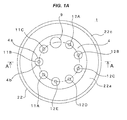
Fig. 1A is a top elevational view showing an embodiment of a pressure sensor according to the present invention; and -
Fig. 1B is a vertical cross sectional view along a line A-A inFig. 1A . -
- 1 pressure sensor
- 2 pressure detection element
- 3 inflow pipe
- 4 base
- 4a through hole
- 4b hermetic seal
- 4c peripheral edge portion
- 4d side surface portion
- 4e upper surface portion
- 5 receiving member
- 5a peripheral edge portion
- 5b side surface portion
- 5c lower surface portion
- 6 diaphragm
- 7 pressure receiving space
- 8 pressurizing space
- 9 ball
- 10 wire
- 11 ((11A-11C) output lead pin
- 12 ((12A-12E) adjusting lead pin
- 14, 15 weld portion
- 22 pinching member
- 22a inclined portion
- 22b cylinder portion
- 22c outer peripheral portion
- Next, a description will be given in detail of a mode for carrying out the present invention with reference to the accompanying drawings.
-
Figs. 1A and1B show a first embodiment of a pressure sensor according to the present invention, and thepressure sensor 1 is provided with apressure detection element 2, abase 4, a receivingmember 5 which is arranged so as to face to thebase 4, adiaphragm 6 which is pinched by thebase 4 and the receivingmember 5, and a pinching member (a retention member) 22 which further pinches (retains) thebase 4 and the receivingmember 5 in a state of pinching thediaphragm 6. An insulative liquid (a sealed liquid) such as an oil is sealed in apressure receiving space 7 between thebase 4 and thediaphragm 6. - The
pressure detection element 2 is fixed to thebase 4 in an inner portion of thepressure receiving space 7. A pressurizingspace 8 serving as a pressure introduction space is formed between the receivingmember 5 and thediaphragm 6, and an internal space of aninflow pipe 3 to which a refrigerant flows is communicated with the pressurizingspace 8. - The
base 4 is formed, for example, by a press work, is provided with a swelling portion which swells upward from an inner side of a peripheral edge portion (a collar portion) 4c, and is formed as a lid shape which is open in its lower end. The swelling portion is constructed by a side surface portion 4d which rises from the inner side of the peripheral edge portion 4c, and anupper surface portion 4e which is provided continuously in the side surface portion 4d. Thepressure detection element 2 is fixed to a lower surface of the swelling portion of the base 4 (that is, a lower surface of theupper surface portion 4e) by an adhesive bonding. - The receiving
member 5 is formed, for example, by a press work, is provided with a swelling portion which swells downward from an inner side of a peripheral edge portion (a collar portion) 5a, and is formed as a dish shape which is open in its upper portion. The swelling portion is constructed by a side surface portion 5b which rises from the inner side of the peripheral edge portion 5a, and a lower surface portion 5c which is provided continuously in the side surface portion 5b. Theinflow pipe 3 is fixed by brazing to an opening in the center of the swelling portion of the receiving member 5 (that is, the center of the lower surface portion 5c). - The
diaphragm 6 is pinched its outer peripheral edge portion between the peripheral edge portion 4c of thebase 4 and the peripheral edge portion 5a of the receivingmember 5, and these threemembers 4 to 6 are simultaneously welded (a weld portion 14) by a laser welding in an outer peripheral edge portion to which an outer peripheral edge portion of thediaphragm 6 is exposed, and are integrated. Thepressure receiving space 7 is charged with a sealing liquid from a filling hole (not shown) which is formed so as to pass through theupper surface portion 4e of thebase 4, and the filling hole is thereafter sealed in the upper surface of thebase 4 by applying a spot welding to aball 9. - The pinching
member 22 is provided with acylinder portion 22b having an inner diameter which is somewhat larger than an outer diameter of thebase 4 and the receivingmember 5 in a state of pinching thediaphragm 6, and an inclined portion 22a which is formed continuously in an upper portion of thecylinder portion 22b via an outerperipheral portion 22c, and is provided so as to be inclined in a direction of a center axis of thecylinder portion 22b, and prevents thebase 4 and the receivingmember 5 from moving away from each other by pinching (retaining) a shoulder portion of the swelling portion of thebase 4 and the peripheral edge portion 5a of the receivingmember 5. The inclined portion 22a is formed as a frustum of a cone in a side elevational shape. The outerperipheral portion 22c is provided with a plane which is vertical to the center axis of the pinchingmember 22. - In the case that the
base 4 and the receivingmember 5 are pinched by the pinchingmember 22, in a state in which thecylinder portion 22b of the pinchingmember 22 is installed to the outer periphery of the peripheral edge portions 4c and 5a of thebase 4 and the receivingmember 5 from thebase 4 side, and an inner surface of the inclined portion 22a comes into contact and engages with the shoulder portion of the swelling portion of the base 4 (that is, the inclined portion of the side surface portion 4d), the lower portion of thecylinder portion 22b is welded and bonded by a laser welding to the side surface of the peripheral edge portion 5a of the receivingmember 5, in a state in which a load F is applied to the outerperipheral portion 22c of the pinchingmember 22 and the lower surface of the peripheral edge portion 5a in the receivingmember 5, in a direction in which thebase 4 and the receivingmember 5 are pressed to each other (a weld portion 15). A durability against a repeated pressure is improved by welding and bonding the pinchingmember 22 in the state in which the load is applied in the direction in which thebase 4 and the receivingmember 5 are pressed to each other. - In this embodiment, the pinching
member 22 is installed to the outer peripheries of the peripheral edge portions 4c and 5a of thebase 4 and the receivingmember 5 from thebase 4 side, and the air gap S is formed between the inner wall of the outerperipheral portion 22c and the peripheral edge portion 4c of thebase 4 in a state in which the inner surface of the inclined portion 22a comes into contact and engages with the shoulder portion of the swelling portion in thebase 4. Therefore, in the case that the load F is applied so as to compress the air gap S, the outerperipheral portion 22c moves to the air gap S side by a small distance, and the inclined portion 22a presses the side surface portion 4d with a snapping force. The pinchingmember 22 is fixed in a state in which the side surface portion 4d of thebase 4 applies a stress to the receivingmember 5 side, by welding and bonding thecylinder portion 22b and the peripheral edge portion 5a under the state mentioned above. - Further, since the
base 4 can be supported closer to the inner side than the peripheral edge portion 4c, it is possible to effectively suppress the deformation of thebase 4 at the high pressure introducing time, an excessive stress applied to ahermetic seal 4b portion, and it is possible to reinforce a breakage preventing effect of the seal portion. - In the case that it is intended to suppress the deformation of the receiving
member 5, the pinchingmember 22 may be attached while being reversed in a vertical direction. In this case, the inclined portion 22a may be engaged with the shoulder portion of the swelling portion (the inclined portion of the side surface portion 5b) in the receivingmember 5 from the receivingmember 5 side, and thecylinder portion 22b may be welded and bonded to the side surface of the peripheral edge portion 4c in thebase 4 in a state in which the load is applied. - The
pressure detection element 2 is an IC chip which is constructed, for example, by a piezoelectric element and a signal processing circuit. The piezoelectric element is one of ferroelectric substances, is also called as a piezoelectric device, and is structured such as to generate an electric voltage in the case that the force such as the vibration or the pressure is applied, and extend and contract on the contrary in the case that the electric voltage is applied. - The
pressure detection element 2 is electrically connected to output lead pins 11 (11A to 11C) and adjusting lead pins 12 (12A to 12E) passing through a through hole 4a formed on theupper surface portion 4e of thebase 4 via awire 10. Theoutput lead pin 11 is structured such as to output a voltage signal in correspondence to the pressure detected by thepressure detection element 2 to an external portion, and the adjustinglead pin 12 is used for compensating the electric voltage at the manufacturing time. In this example, three output lead pins 11A to 11C, the adjusting lead pins 12A to 12E and the filling hole mentioned above are arranged on the same circumference from the center of thebase 4 by a uniform angle. - The through hole 4a of the
base 4 passes theoutput lead pin 11 and the adjustinglead pin 12 therethrough, and is thereafter sealed by thehermetic seal 4b so as to prevent the sealed liquid from leaking. Theoutput lead pin 11 is connected to a base plate (not shown) in its upper end portion, and the base plate is connected to an external output lead wire further via a connector (not shown). - In the
pressure sensor 1 having the structure mentioned above, the pressure of the pressurizingspace 8 is changed by the pressure change of the refrigerant flowing into from the inflow pipe, and changes thediaphragm 6. The pressure of the sealed liquid in the inner portion of thepressure receiving space 7 is changed by the deformation of thediaphragm 6, and the pressure change is propagated to thepressure detection element 2. The pressure detected by thepressure detection element 2 is converted into the electric voltage, and a predetermined voltage compensation is carried out in correspondence to the characteristic of thepressure sensor 1 by a compensating circuit. The compensated voltage signal is transmitted to the external output lead wire via theoutput lead pin 11, the base plate and the connector. - In the case that the
pressure sensor 1 is used for detecting the pressure of the refrigerant flow path of the air conditioning device using the high pressure refrigerant such as CO2, the high pressure of the refrigerant flowing into from theinflow pipe 3 is repeatedly applied to the pressurizingspace 8, and the great force is repeatedly applied in a direction of moving thebase 4 and the receivingmember 5 away from each other. However, since the pinchingmember 22 is welded and bonded in the state in which thebase 4 and the receivingmember 5 are applied the load in the direction in which they are pressed to each other, and the respective peripheral edge portions of thebase 4 and the receivingmember 5 are pinched by the pinchingmember 22, as well as the receivingmember 5 and thediaphragm 6 are integrated by theweld portion 14, there is no risk that a crack is generated in theweld portion 14, and it is possible to effectively prevent thepressure sensor 1 from being broken. - In the embodiment mentioned above, the outer
peripheral portion 22c is formed as the plane which is vertical to the center axis of the pinchingmember 22, and the pinchingmember 22 is welded and bonded by applying the load F to the outerperipheral portion 22c and the lower surface of the peripheral edge portion 5a of the receivingmember 5 in the direction in which thebase 4 and the receivingmember 5 are pressed to each other, however, the position to which the load F is applied, is not limited to the outerperipheral portion 22c, but an outer peripheral side of the inclined portion 22a of the pinchingmember 22 may be utilized so that the air gap S is compressed. In this case, it is possible to omit the plane portion (the outerperipheral portion 22c) which is provided in the boundary portion between thecylinder portion 22b and the inclined portion 22a, and is vertical to the center axis of the pinchingmember 22. - Further, the description is given on the assumption that the load F is applied so that the air gap S is compressed, however, the present invention is not limited particularly to this, but the load F may be applies so as to directly press the contact portion between the inner surface of the inclined portion 22a and the
base 4 or the receivingmember 5 from the outer side of the inclined portion 22a, the contact portion coming into contact in the case that the pinchingmember 22 is installed from thebase 4 or the receivingmember 5 side. In this case, the air gap S may be omitted.
Claims (3)
- A pressure sensor comprising:a pressure detection element;a base in which said pressure detection element is fixed to an inner surface;a receiving member which is arranged so as to face to said base;a diaphragm which is pinched by said base and said receiving member;a pinching member which pinches said base and said receiving member in a state of pinching said diaphragm in such a manner as to prevent both of said base and said receiving member from moving away from each other, the pinching member being installed from any one side of said base and said receiving member, and being bonded by welding to any other side of said base and said receiving member in a state in which a load is applied in a direction in which both of the base and the receiving member are pressed from each other; anda liquid which is sealed in a space between said base and said diaphragm,wherein the pressure in the space between said receiving member and said diaphragm is transmitted to said pressure detection element via said diaphragm and said liquid.
- The pressure sensor according to claim 1, wherein said load is applied so as to compress an air gap formed between said pinching member and one of said base and said receiving member.
- The pressure sensor according to claim 1 or 2, wherein an outer peripheral portion of said pinching member has a plane which is vertical to a center axis of said pinching member.
Applications Claiming Priority (1)
| Application Number | Priority Date | Filing Date | Title |
|---|---|---|---|
| JP2013071168A JP6106004B2 (en) | 2013-03-29 | 2013-03-29 | Pressure sensor |
Publications (3)
| Publication Number | Publication Date |
|---|---|
| EP2793010A2 true EP2793010A2 (en) | 2014-10-22 |
| EP2793010A3 EP2793010A3 (en) | 2015-02-25 |
| EP2793010B1 EP2793010B1 (en) | 2019-05-15 |
Family
ID=50345871
Family Applications (1)
| Application Number | Title | Priority Date | Filing Date |
|---|---|---|---|
| EP14161208.5A Active EP2793010B1 (en) | 2013-03-29 | 2014-03-24 | Pressure sensor |
Country Status (3)
| Country | Link |
|---|---|
| EP (1) | EP2793010B1 (en) |
| JP (1) | JP6106004B2 (en) |
| CN (1) | CN104075838B (en) |
Cited By (3)
| Publication number | Priority date | Publication date | Assignee | Title |
|---|---|---|---|---|
| EP3193148A1 (en) * | 2016-08-18 | 2017-07-19 | Siemens Aktiengesellschaft | Pressure sensor |
| WO2021061409A1 (en) * | 2019-09-23 | 2021-04-01 | Rosemount Inc. | High pressure capsule and header for process fluid pressure transmitter |
| US11852131B2 (en) | 2017-09-25 | 2023-12-26 | Carrier Corporation | Pressure safety shutoff |
Families Citing this family (5)
| Publication number | Priority date | Publication date | Assignee | Title |
|---|---|---|---|---|
| JP6564914B1 (en) * | 2018-06-22 | 2019-08-21 | 日機装株式会社 | Medical device and manufacturing method thereof |
| JP2020008306A (en) * | 2018-07-03 | 2020-01-16 | 株式会社不二工機 | Pressure detection unit and pressure sensor using the same |
| CN109534282B (en) * | 2018-10-26 | 2020-06-16 | 江西新力传感科技有限公司 | Production process of dielectric isolation type pressure sensor based on flip chip |
| JP7005550B2 (en) * | 2019-03-29 | 2022-01-21 | 長野計器株式会社 | Manufacturing method of physical quantity measuring device and physical quantity measuring device |
| CN116727998B (en) * | 2023-08-14 | 2023-10-13 | 河北宾宏石化设备有限公司 | Oblique tee bend pipe fitting fixed-position welding equipment |
Citations (1)
| Publication number | Priority date | Publication date | Assignee | Title |
|---|---|---|---|---|
| JP2005308397A (en) | 2004-04-16 | 2005-11-04 | Saginomiya Seisakusho Inc | Pressure sensor |
Family Cites Families (17)
| Publication number | Priority date | Publication date | Assignee | Title |
|---|---|---|---|---|
| US3602744A (en) * | 1969-06-11 | 1971-08-31 | Kistler Instr Corp | Welded pressure transducer |
| JPS5950326A (en) * | 1982-09-16 | 1984-03-23 | Yamatake Honeywell Co Ltd | Fixing method of diaphragm |
| JPH0723256U (en) * | 1993-10-04 | 1995-04-25 | 太平洋工業株式会社 | Capacitive pressure detector |
| JP4003363B2 (en) * | 1999-12-24 | 2007-11-07 | 株式会社デンソー | Combustion pressure sensor structure |
| DE10032616A1 (en) * | 2000-07-08 | 2002-01-24 | Mhm Harzbecher Medizintechnik | System element for transducer connection in pressure-monitoring sets for extracorporeal circuits, e.g. in open-heart surgery, has a measuring chamber with a membrane which fits in a special channel in the housing |
| JP3603772B2 (en) * | 2000-09-26 | 2004-12-22 | 株式会社デンソー | Pressure sensor |
| JP2005106796A (en) * | 2003-08-05 | 2005-04-21 | Fuji Koki Corp | Pressure sensor |
| US7070086B2 (en) * | 2004-03-03 | 2006-07-04 | Honeywell International Inc. | Sensor pre-load and weld fixture apparatus and method |
| JP2006208043A (en) * | 2005-01-25 | 2006-08-10 | Denso Corp | Manufacturing method of pressure detecting device |
| JP4848904B2 (en) * | 2006-09-13 | 2011-12-28 | 株式会社デンソー | Pressure sensor |
| JP5142742B2 (en) * | 2007-02-16 | 2013-02-13 | 株式会社デンソー | Pressure sensor and manufacturing method thereof |
| JP2009085723A (en) * | 2007-09-28 | 2009-04-23 | Denso Corp | Pressure detecting device and manufacturing method thereof |
| JP2009109313A (en) * | 2007-10-30 | 2009-05-21 | Denso Corp | Pressure temperature combined sensor |
| CN101546806A (en) * | 2008-03-28 | 2009-09-30 | 松下电器产业株式会社 | Sensor device and fabrication method for the same |
| IT1391187B1 (en) * | 2008-08-01 | 2011-11-18 | Eltek Spa | PRESSURE SENSOR DEVICE |
| CN102980713B (en) * | 2011-09-02 | 2016-04-27 | 株式会社不二工机 | Pressure transducer |
| KR102009043B1 (en) * | 2011-09-02 | 2019-08-08 | 가부시기가이샤 후지고오키 | Pressure sensor |
-
2013
- 2013-03-29 JP JP2013071168A patent/JP6106004B2/en active Active
- 2013-12-24 CN CN201310724382.8A patent/CN104075838B/en active Active
-
2014
- 2014-03-24 EP EP14161208.5A patent/EP2793010B1/en active Active
Patent Citations (1)
| Publication number | Priority date | Publication date | Assignee | Title |
|---|---|---|---|---|
| JP2005308397A (en) | 2004-04-16 | 2005-11-04 | Saginomiya Seisakusho Inc | Pressure sensor |
Cited By (4)
| Publication number | Priority date | Publication date | Assignee | Title |
|---|---|---|---|---|
| EP3193148A1 (en) * | 2016-08-18 | 2017-07-19 | Siemens Aktiengesellschaft | Pressure sensor |
| US11852131B2 (en) | 2017-09-25 | 2023-12-26 | Carrier Corporation | Pressure safety shutoff |
| WO2021061409A1 (en) * | 2019-09-23 | 2021-04-01 | Rosemount Inc. | High pressure capsule and header for process fluid pressure transmitter |
| US11262771B2 (en) | 2019-09-23 | 2022-03-01 | Rosemount Inc. | High pressure capsule and header for process fluid pressure transmitter |
Also Published As
| Publication number | Publication date |
|---|---|
| CN104075838A (en) | 2014-10-01 |
| EP2793010B1 (en) | 2019-05-15 |
| EP2793010A3 (en) | 2015-02-25 |
| CN104075838B (en) | 2018-02-13 |
| JP2014194388A (en) | 2014-10-09 |
| JP6106004B2 (en) | 2017-03-29 |
Similar Documents
| Publication | Publication Date | Title |
|---|---|---|
| EP2793010B1 (en) | Pressure sensor | |
| JP6812162B2 (en) | Sealed pressure sensor | |
| US7950287B2 (en) | Pressure-sensor system | |
| KR102009043B1 (en) | Pressure sensor | |
| CN105181223B (en) | The manufacture method of differential pressure pick-up and differential pressure pick-up | |
| JP5998379B2 (en) | Sensor device package and method | |
| KR101460878B1 (en) | Pressure sensor chip | |
| KR102266018B1 (en) | Physical quantity measurement sensor | |
| CN100390516C (en) | Pressure Sensor | |
| JP2011257393A (en) | Air-tight sealed pressure sensing apparatus | |
| CN105203249A (en) | Double Diaphragm Pressure Sensor | |
| CN105277311A (en) | Process isolation diaphragm assembly for metal process seal | |
| US20200025638A1 (en) | Differential pressure sensor chip, differential pressure transmitter, and method for manufacturing differential pressure sensor chip | |
| KR20170096575A (en) | Pressure detecting unit and pressure sensor using the same | |
| KR20170096577A (en) | Pressure detecting unit, pressure sensor using the same, and manufacturing method of pressure detecting unit | |
| KR102597323B1 (en) | Pressure sensor and manufacturing thereof | |
| KR20140034692A (en) | Pressure sensor | |
| US11137307B2 (en) | Pressure sensor | |
| CN102980713B (en) | Pressure transducer | |
| KR20200011359A (en) | Pressure sensor chip | |
| JP6748011B2 (en) | Differential pressure sensor chip, differential pressure transmitter, and method of manufacturing differential pressure sensor chip | |
| JP6362497B2 (en) | Pressure sensor | |
| JP2012242351A (en) | Differential pressure and pressure measuring device | |
| JP2017102043A (en) | Pressure sensor | |
| KR20130139764A (en) | Pressure sensor |
Legal Events
| Date | Code | Title | Description |
|---|---|---|---|
| PUAI | Public reference made under article 153(3) epc to a published international application that has entered the european phase |
Free format text: ORIGINAL CODE: 0009012 |
|
| 17P | Request for examination filed |
Effective date: 20140324 |
|
| AK | Designated contracting states |
Kind code of ref document: A2 Designated state(s): AL AT BE BG CH CY CZ DE DK EE ES FI FR GB GR HR HU IE IS IT LI LT LU LV MC MK MT NL NO PL PT RO RS SE SI SK SM TR |
|
| AX | Request for extension of the european patent |
Extension state: BA ME |
|
| PUAL | Search report despatched |
Free format text: ORIGINAL CODE: 0009013 |
|
| AK | Designated contracting states |
Kind code of ref document: A3 Designated state(s): AL AT BE BG CH CY CZ DE DK EE ES FI FR GB GR HR HU IE IS IT LI LT LU LV MC MK MT NL NO PL PT RO RS SE SI SK SM TR |
|
| AX | Request for extension of the european patent |
Extension state: BA ME |
|
| RIC1 | Information provided on ipc code assigned before grant |
Ipc: G01L 7/08 20060101ALI20150119BHEP Ipc: G01L 19/06 20060101ALI20150119BHEP Ipc: G01L 19/00 20060101AFI20150119BHEP Ipc: G01L 19/14 20060101ALI20150119BHEP |
|
| R17P | Request for examination filed (corrected) |
Effective date: 20150617 |
|
| RBV | Designated contracting states (corrected) |
Designated state(s): AL AT BE BG CH CY CZ DE DK EE ES FI FR GB GR HR HU IE IS IT LI LT LU LV MC MK MT NL NO PL PT RO RS SE SI SK SM TR |
|
| STAA | Information on the status of an ep patent application or granted ep patent |
Free format text: STATUS: EXAMINATION IS IN PROGRESS |
|
| 17Q | First examination report despatched |
Effective date: 20180228 |
|
| GRAP | Despatch of communication of intention to grant a patent |
Free format text: ORIGINAL CODE: EPIDOSNIGR1 |
|
| STAA | Information on the status of an ep patent application or granted ep patent |
Free format text: STATUS: GRANT OF PATENT IS INTENDED |
|
| INTG | Intention to grant announced |
Effective date: 20181207 |
|
| GRAS | Grant fee paid |
Free format text: ORIGINAL CODE: EPIDOSNIGR3 |
|
| GRAA | (expected) grant |
Free format text: ORIGINAL CODE: 0009210 |
|
| STAA | Information on the status of an ep patent application or granted ep patent |
Free format text: STATUS: THE PATENT HAS BEEN GRANTED |
|
| AK | Designated contracting states |
Kind code of ref document: B1 Designated state(s): AL AT BE BG CH CY CZ DE DK EE ES FI FR GB GR HR HU IE IS IT LI LT LU LV MC MK MT NL NO PL PT RO RS SE SI SK SM TR |
|
| REG | Reference to a national code |
Ref country code: GB Ref legal event code: FG4D Ref country code: CH Ref legal event code: EP |
|
| REG | Reference to a national code |
Ref country code: DE Ref legal event code: R096 Ref document number: 602014046693 Country of ref document: DE |
|
| REG | Reference to a national code |
Ref country code: IE Ref legal event code: FG4D |
|
| REG | Reference to a national code |
Ref country code: NL Ref legal event code: MP Effective date: 20190515 |
|
| REG | Reference to a national code |
Ref country code: LT Ref legal event code: MG4D |
|
| PG25 | Lapsed in a contracting state [announced via postgrant information from national office to epo] |
Ref country code: LT Free format text: LAPSE BECAUSE OF FAILURE TO SUBMIT A TRANSLATION OF THE DESCRIPTION OR TO PAY THE FEE WITHIN THE PRESCRIBED TIME-LIMIT Effective date: 20190515 Ref country code: NO Free format text: LAPSE BECAUSE OF FAILURE TO SUBMIT A TRANSLATION OF THE DESCRIPTION OR TO PAY THE FEE WITHIN THE PRESCRIBED TIME-LIMIT Effective date: 20190815 Ref country code: FI Free format text: LAPSE BECAUSE OF FAILURE TO SUBMIT A TRANSLATION OF THE DESCRIPTION OR TO PAY THE FEE WITHIN THE PRESCRIBED TIME-LIMIT Effective date: 20190515 Ref country code: HR Free format text: LAPSE BECAUSE OF FAILURE TO SUBMIT A TRANSLATION OF THE DESCRIPTION OR TO PAY THE FEE WITHIN THE PRESCRIBED TIME-LIMIT Effective date: 20190515 Ref country code: NL Free format text: LAPSE BECAUSE OF FAILURE TO SUBMIT A TRANSLATION OF THE DESCRIPTION OR TO PAY THE FEE WITHIN THE PRESCRIBED TIME-LIMIT Effective date: 20190515 Ref country code: SE Free format text: LAPSE BECAUSE OF FAILURE TO SUBMIT A TRANSLATION OF THE DESCRIPTION OR TO PAY THE FEE WITHIN THE PRESCRIBED TIME-LIMIT Effective date: 20190515 Ref country code: ES Free format text: LAPSE BECAUSE OF FAILURE TO SUBMIT A TRANSLATION OF THE DESCRIPTION OR TO PAY THE FEE WITHIN THE PRESCRIBED TIME-LIMIT Effective date: 20190515 Ref country code: PT Free format text: LAPSE BECAUSE OF FAILURE TO SUBMIT A TRANSLATION OF THE DESCRIPTION OR TO PAY THE FEE WITHIN THE PRESCRIBED TIME-LIMIT Effective date: 20190915 Ref country code: AL Free format text: LAPSE BECAUSE OF FAILURE TO SUBMIT A TRANSLATION OF THE DESCRIPTION OR TO PAY THE FEE WITHIN THE PRESCRIBED TIME-LIMIT Effective date: 20190515 |
|
| PG25 | Lapsed in a contracting state [announced via postgrant information from national office to epo] |
Ref country code: LV Free format text: LAPSE BECAUSE OF FAILURE TO SUBMIT A TRANSLATION OF THE DESCRIPTION OR TO PAY THE FEE WITHIN THE PRESCRIBED TIME-LIMIT Effective date: 20190515 Ref country code: BG Free format text: LAPSE BECAUSE OF FAILURE TO SUBMIT A TRANSLATION OF THE DESCRIPTION OR TO PAY THE FEE WITHIN THE PRESCRIBED TIME-LIMIT Effective date: 20190815 Ref country code: GR Free format text: LAPSE BECAUSE OF FAILURE TO SUBMIT A TRANSLATION OF THE DESCRIPTION OR TO PAY THE FEE WITHIN THE PRESCRIBED TIME-LIMIT Effective date: 20190816 Ref country code: RS Free format text: LAPSE BECAUSE OF FAILURE TO SUBMIT A TRANSLATION OF THE DESCRIPTION OR TO PAY THE FEE WITHIN THE PRESCRIBED TIME-LIMIT Effective date: 20190515 |
|
| REG | Reference to a national code |
Ref country code: AT Ref legal event code: MK05 Ref document number: 1134002 Country of ref document: AT Kind code of ref document: T Effective date: 20190515 |
|
| PG25 | Lapsed in a contracting state [announced via postgrant information from national office to epo] |
Ref country code: RO Free format text: LAPSE BECAUSE OF FAILURE TO SUBMIT A TRANSLATION OF THE DESCRIPTION OR TO PAY THE FEE WITHIN THE PRESCRIBED TIME-LIMIT Effective date: 20190515 Ref country code: EE Free format text: LAPSE BECAUSE OF FAILURE TO SUBMIT A TRANSLATION OF THE DESCRIPTION OR TO PAY THE FEE WITHIN THE PRESCRIBED TIME-LIMIT Effective date: 20190515 Ref country code: CZ Free format text: LAPSE BECAUSE OF FAILURE TO SUBMIT A TRANSLATION OF THE DESCRIPTION OR TO PAY THE FEE WITHIN THE PRESCRIBED TIME-LIMIT Effective date: 20190515 Ref country code: SK Free format text: LAPSE BECAUSE OF FAILURE TO SUBMIT A TRANSLATION OF THE DESCRIPTION OR TO PAY THE FEE WITHIN THE PRESCRIBED TIME-LIMIT Effective date: 20190515 Ref country code: DK Free format text: LAPSE BECAUSE OF FAILURE TO SUBMIT A TRANSLATION OF THE DESCRIPTION OR TO PAY THE FEE WITHIN THE PRESCRIBED TIME-LIMIT Effective date: 20190515 Ref country code: AT Free format text: LAPSE BECAUSE OF FAILURE TO SUBMIT A TRANSLATION OF THE DESCRIPTION OR TO PAY THE FEE WITHIN THE PRESCRIBED TIME-LIMIT Effective date: 20190515 |
|
| REG | Reference to a national code |
Ref country code: DE Ref legal event code: R097 Ref document number: 602014046693 Country of ref document: DE |
|
| PG25 | Lapsed in a contracting state [announced via postgrant information from national office to epo] |
Ref country code: SM Free format text: LAPSE BECAUSE OF FAILURE TO SUBMIT A TRANSLATION OF THE DESCRIPTION OR TO PAY THE FEE WITHIN THE PRESCRIBED TIME-LIMIT Effective date: 20190515 Ref country code: IT Free format text: LAPSE BECAUSE OF FAILURE TO SUBMIT A TRANSLATION OF THE DESCRIPTION OR TO PAY THE FEE WITHIN THE PRESCRIBED TIME-LIMIT Effective date: 20190515 |
|
| PLBE | No opposition filed within time limit |
Free format text: ORIGINAL CODE: 0009261 |
|
| STAA | Information on the status of an ep patent application or granted ep patent |
Free format text: STATUS: NO OPPOSITION FILED WITHIN TIME LIMIT |
|
| PG25 | Lapsed in a contracting state [announced via postgrant information from national office to epo] |
Ref country code: TR Free format text: LAPSE BECAUSE OF FAILURE TO SUBMIT A TRANSLATION OF THE DESCRIPTION OR TO PAY THE FEE WITHIN THE PRESCRIBED TIME-LIMIT Effective date: 20190515 |
|
| 26N | No opposition filed |
Effective date: 20200218 |
|
| PG25 | Lapsed in a contracting state [announced via postgrant information from national office to epo] |
Ref country code: PL Free format text: LAPSE BECAUSE OF FAILURE TO SUBMIT A TRANSLATION OF THE DESCRIPTION OR TO PAY THE FEE WITHIN THE PRESCRIBED TIME-LIMIT Effective date: 20190515 |
|
| PG25 | Lapsed in a contracting state [announced via postgrant information from national office to epo] |
Ref country code: SI Free format text: LAPSE BECAUSE OF FAILURE TO SUBMIT A TRANSLATION OF THE DESCRIPTION OR TO PAY THE FEE WITHIN THE PRESCRIBED TIME-LIMIT Effective date: 20190515 |
|
| PG25 | Lapsed in a contracting state [announced via postgrant information from national office to epo] |
Ref country code: MC Free format text: LAPSE BECAUSE OF FAILURE TO SUBMIT A TRANSLATION OF THE DESCRIPTION OR TO PAY THE FEE WITHIN THE PRESCRIBED TIME-LIMIT Effective date: 20190515 |
|
| REG | Reference to a national code |
Ref country code: CH Ref legal event code: PL |
|
| PG25 | Lapsed in a contracting state [announced via postgrant information from national office to epo] |
Ref country code: LU Free format text: LAPSE BECAUSE OF NON-PAYMENT OF DUE FEES Effective date: 20200324 |
|
| PG25 | Lapsed in a contracting state [announced via postgrant information from national office to epo] |
Ref country code: CH Free format text: LAPSE BECAUSE OF NON-PAYMENT OF DUE FEES Effective date: 20200331 Ref country code: LI Free format text: LAPSE BECAUSE OF NON-PAYMENT OF DUE FEES Effective date: 20200331 Ref country code: IE Free format text: LAPSE BECAUSE OF NON-PAYMENT OF DUE FEES Effective date: 20200324 |
|
| GBPC | Gb: european patent ceased through non-payment of renewal fee |
Effective date: 20200324 |
|
| PG25 | Lapsed in a contracting state [announced via postgrant information from national office to epo] |
Ref country code: GB Free format text: LAPSE BECAUSE OF NON-PAYMENT OF DUE FEES Effective date: 20200324 |
|
| PGFP | Annual fee paid to national office [announced via postgrant information from national office to epo] |
Ref country code: FR Payment date: 20210210 Year of fee payment: 8 |
|
| PGFP | Annual fee paid to national office [announced via postgrant information from national office to epo] |
Ref country code: BE Payment date: 20210217 Year of fee payment: 8 Ref country code: DE Payment date: 20210310 Year of fee payment: 8 |
|
| PG25 | Lapsed in a contracting state [announced via postgrant information from national office to epo] |
Ref country code: MT Free format text: LAPSE BECAUSE OF FAILURE TO SUBMIT A TRANSLATION OF THE DESCRIPTION OR TO PAY THE FEE WITHIN THE PRESCRIBED TIME-LIMIT Effective date: 20190515 Ref country code: CY Free format text: LAPSE BECAUSE OF FAILURE TO SUBMIT A TRANSLATION OF THE DESCRIPTION OR TO PAY THE FEE WITHIN THE PRESCRIBED TIME-LIMIT Effective date: 20190515 |
|
| PG25 | Lapsed in a contracting state [announced via postgrant information from national office to epo] |
Ref country code: MK Free format text: LAPSE BECAUSE OF FAILURE TO SUBMIT A TRANSLATION OF THE DESCRIPTION OR TO PAY THE FEE WITHIN THE PRESCRIBED TIME-LIMIT Effective date: 20190515 Ref country code: IS Free format text: LAPSE BECAUSE OF FAILURE TO SUBMIT A TRANSLATION OF THE DESCRIPTION OR TO PAY THE FEE WITHIN THE PRESCRIBED TIME-LIMIT Effective date: 20190915 |
|
| REG | Reference to a national code |
Ref country code: DE Ref legal event code: R119 Ref document number: 602014046693 Country of ref document: DE |
|
| REG | Reference to a national code |
Ref country code: BE Ref legal event code: MM Effective date: 20220331 |
|
| PG25 | Lapsed in a contracting state [announced via postgrant information from national office to epo] |
Ref country code: FR Free format text: LAPSE BECAUSE OF NON-PAYMENT OF DUE FEES Effective date: 20220331 Ref country code: DE Free format text: LAPSE BECAUSE OF NON-PAYMENT OF DUE FEES Effective date: 20221001 |
|
| PG25 | Lapsed in a contracting state [announced via postgrant information from national office to epo] |
Ref country code: BE Free format text: LAPSE BECAUSE OF NON-PAYMENT OF DUE FEES Effective date: 20220331 |