EP2792873A1 - Work vehicle and method for controlling work vehicle - Google Patents
Work vehicle and method for controlling work vehicle Download PDFInfo
- Publication number
- EP2792873A1 EP2792873A1 EP12784409.0A EP12784409A EP2792873A1 EP 2792873 A1 EP2792873 A1 EP 2792873A1 EP 12784409 A EP12784409 A EP 12784409A EP 2792873 A1 EP2792873 A1 EP 2792873A1
- Authority
- EP
- European Patent Office
- Prior art keywords
- upper limit
- opening degree
- work
- throttle opening
- throttle
- Prior art date
- Legal status (The legal status is an assumption and is not a legal conclusion. Google has not performed a legal analysis and makes no representation as to the accuracy of the status listed.)
- Granted
Links
Images






Classifications
-
- E—FIXED CONSTRUCTIONS
- E02—HYDRAULIC ENGINEERING; FOUNDATIONS; SOIL SHIFTING
- E02F—DREDGING; SOIL-SHIFTING
- E02F9/00—Component parts of dredgers or soil-shifting machines, not restricted to one of the kinds covered by groups E02F3/00 - E02F7/00
- E02F9/20—Drives; Control devices
- E02F9/22—Hydraulic or pneumatic drives
- E02F9/2246—Control of prime movers, e.g. depending on the hydraulic load of work tools
-
- F—MECHANICAL ENGINEERING; LIGHTING; HEATING; WEAPONS; BLASTING
- F15—FLUID-PRESSURE ACTUATORS; HYDRAULICS OR PNEUMATICS IN GENERAL
- F15B—SYSTEMS ACTING BY MEANS OF FLUIDS IN GENERAL; FLUID-PRESSURE ACTUATORS, e.g. SERVOMOTORS; DETAILS OF FLUID-PRESSURE SYSTEMS, NOT OTHERWISE PROVIDED FOR
- F15B11/00—Servomotor systems without provision for follow-up action; Circuits therefor
- F15B11/08—Servomotor systems without provision for follow-up action; Circuits therefor with only one servomotor
-
- B—PERFORMING OPERATIONS; TRANSPORTING
- B60—VEHICLES IN GENERAL
- B60W—CONJOINT CONTROL OF VEHICLE SUB-UNITS OF DIFFERENT TYPE OR DIFFERENT FUNCTION; CONTROL SYSTEMS SPECIALLY ADAPTED FOR HYBRID VEHICLES; ROAD VEHICLE DRIVE CONTROL SYSTEMS FOR PURPOSES NOT RELATED TO THE CONTROL OF A PARTICULAR SUB-UNIT
- B60W10/00—Conjoint control of vehicle sub-units of different type or different function
- B60W10/04—Conjoint control of vehicle sub-units of different type or different function including control of propulsion units
- B60W10/06—Conjoint control of vehicle sub-units of different type or different function including control of propulsion units including control of combustion engines
-
- B—PERFORMING OPERATIONS; TRANSPORTING
- B60—VEHICLES IN GENERAL
- B60W—CONJOINT CONTROL OF VEHICLE SUB-UNITS OF DIFFERENT TYPE OR DIFFERENT FUNCTION; CONTROL SYSTEMS SPECIALLY ADAPTED FOR HYBRID VEHICLES; ROAD VEHICLE DRIVE CONTROL SYSTEMS FOR PURPOSES NOT RELATED TO THE CONTROL OF A PARTICULAR SUB-UNIT
- B60W10/00—Conjoint control of vehicle sub-units of different type or different function
- B60W10/30—Conjoint control of vehicle sub-units of different type or different function including control of auxiliary equipment, e.g. air-conditioning compressors or oil pumps
-
- B—PERFORMING OPERATIONS; TRANSPORTING
- B60—VEHICLES IN GENERAL
- B60W—CONJOINT CONTROL OF VEHICLE SUB-UNITS OF DIFFERENT TYPE OR DIFFERENT FUNCTION; CONTROL SYSTEMS SPECIALLY ADAPTED FOR HYBRID VEHICLES; ROAD VEHICLE DRIVE CONTROL SYSTEMS FOR PURPOSES NOT RELATED TO THE CONTROL OF A PARTICULAR SUB-UNIT
- B60W30/00—Purposes of road vehicle drive control systems not related to the control of a particular sub-unit, e.g. of systems using conjoint control of vehicle sub-units
- B60W30/18—Propelling the vehicle
- B60W30/188—Controlling power parameters of the driveline, e.g. determining the required power
- B60W30/1882—Controlling power parameters of the driveline, e.g. determining the required power characterised by the working point of the engine, e.g. by using engine output chart
-
- E—FIXED CONSTRUCTIONS
- E02—HYDRAULIC ENGINEERING; FOUNDATIONS; SOIL SHIFTING
- E02F—DREDGING; SOIL-SHIFTING
- E02F3/00—Dredgers; Soil-shifting machines
- E02F3/04—Dredgers; Soil-shifting machines mechanically-driven
- E02F3/28—Dredgers; Soil-shifting machines mechanically-driven with digging tools mounted on a dipper- or bucket-arm, i.e. there is either one arm or a pair of arms, e.g. dippers, buckets
- E02F3/36—Component parts
-
- E—FIXED CONSTRUCTIONS
- E02—HYDRAULIC ENGINEERING; FOUNDATIONS; SOIL SHIFTING
- E02F—DREDGING; SOIL-SHIFTING
- E02F3/00—Dredgers; Soil-shifting machines
- E02F3/04—Dredgers; Soil-shifting machines mechanically-driven
- E02F3/28—Dredgers; Soil-shifting machines mechanically-driven with digging tools mounted on a dipper- or bucket-arm, i.e. there is either one arm or a pair of arms, e.g. dippers, buckets
- E02F3/36—Component parts
- E02F3/42—Drives for dippers, buckets, dipper-arms or bucket-arms
- E02F3/422—Drive systems for bucket-arms, front-end loaders, dumpers or the like
-
- E—FIXED CONSTRUCTIONS
- E02—HYDRAULIC ENGINEERING; FOUNDATIONS; SOIL SHIFTING
- E02F—DREDGING; SOIL-SHIFTING
- E02F9/00—Component parts of dredgers or soil-shifting machines, not restricted to one of the kinds covered by groups E02F3/00 - E02F7/00
- E02F9/20—Drives; Control devices
- E02F9/22—Hydraulic or pneumatic drives
- E02F9/2253—Controlling the travelling speed of vehicles, e.g. adjusting travelling speed according to implement loads, control of hydrostatic transmission
-
- E—FIXED CONSTRUCTIONS
- E02—HYDRAULIC ENGINEERING; FOUNDATIONS; SOIL SHIFTING
- E02F—DREDGING; SOIL-SHIFTING
- E02F9/00—Component parts of dredgers or soil-shifting machines, not restricted to one of the kinds covered by groups E02F3/00 - E02F7/00
- E02F9/20—Drives; Control devices
- E02F9/22—Hydraulic or pneumatic drives
- E02F9/2278—Hydraulic circuits
- E02F9/2289—Closed circuit
-
- E—FIXED CONSTRUCTIONS
- E02—HYDRAULIC ENGINEERING; FOUNDATIONS; SOIL SHIFTING
- E02F—DREDGING; SOIL-SHIFTING
- E02F9/00—Component parts of dredgers or soil-shifting machines, not restricted to one of the kinds covered by groups E02F3/00 - E02F7/00
- E02F9/20—Drives; Control devices
- E02F9/22—Hydraulic or pneumatic drives
- E02F9/2278—Hydraulic circuits
- E02F9/2292—Systems with two or more pumps
-
- E—FIXED CONSTRUCTIONS
- E02—HYDRAULIC ENGINEERING; FOUNDATIONS; SOIL SHIFTING
- E02F—DREDGING; SOIL-SHIFTING
- E02F9/00—Component parts of dredgers or soil-shifting machines, not restricted to one of the kinds covered by groups E02F3/00 - E02F7/00
- E02F9/20—Drives; Control devices
- E02F9/22—Hydraulic or pneumatic drives
- E02F9/2278—Hydraulic circuits
- E02F9/2296—Systems with a variable displacement pump
-
- F—MECHANICAL ENGINEERING; LIGHTING; HEATING; WEAPONS; BLASTING
- F02—COMBUSTION ENGINES; HOT-GAS OR COMBUSTION-PRODUCT ENGINE PLANTS
- F02D—CONTROLLING COMBUSTION ENGINES
- F02D11/00—Arrangements for, or adaptations to, non-automatic engine control initiation means, e.g. operator initiated
- F02D11/06—Arrangements for, or adaptations to, non-automatic engine control initiation means, e.g. operator initiated characterised by non-mechanical control linkages, e.g. fluid control linkages or by control linkages with power drive or assistance
- F02D11/10—Arrangements for, or adaptations to, non-automatic engine control initiation means, e.g. operator initiated characterised by non-mechanical control linkages, e.g. fluid control linkages or by control linkages with power drive or assistance of the electric type
- F02D11/105—Arrangements for, or adaptations to, non-automatic engine control initiation means, e.g. operator initiated characterised by non-mechanical control linkages, e.g. fluid control linkages or by control linkages with power drive or assistance of the electric type characterised by the function converting demand to actuation, e.g. a map indicating relations between an accelerator pedal position and throttle valve opening or target engine torque
-
- F—MECHANICAL ENGINEERING; LIGHTING; HEATING; WEAPONS; BLASTING
- F15—FLUID-PRESSURE ACTUATORS; HYDRAULICS OR PNEUMATICS IN GENERAL
- F15B—SYSTEMS ACTING BY MEANS OF FLUIDS IN GENERAL; FLUID-PRESSURE ACTUATORS, e.g. SERVOMOTORS; DETAILS OF FLUID-PRESSURE SYSTEMS, NOT OTHERWISE PROVIDED FOR
- F15B13/00—Details of servomotor systems ; Valves for servomotor systems
- F15B13/02—Fluid distribution or supply devices characterised by their adaptation to the control of servomotors
-
- F—MECHANICAL ENGINEERING; LIGHTING; HEATING; WEAPONS; BLASTING
- F16—ENGINEERING ELEMENTS AND UNITS; GENERAL MEASURES FOR PRODUCING AND MAINTAINING EFFECTIVE FUNCTIONING OF MACHINES OR INSTALLATIONS; THERMAL INSULATION IN GENERAL
- F16H—GEARING
- F16H61/00—Control functions within control units of change-speed- or reversing-gearings for conveying rotary motion ; Control of exclusively fluid gearing, friction gearing, gearings with endless flexible members or other particular types of gearing
- F16H61/38—Control of exclusively fluid gearing
- F16H61/40—Control of exclusively fluid gearing hydrostatic
- F16H61/42—Control of exclusively fluid gearing hydrostatic involving adjustment of a pump or motor with adjustable output or capacity
- F16H61/421—Motor capacity control by electro-hydraulic control means, e.g. using solenoid valves
-
- F—MECHANICAL ENGINEERING; LIGHTING; HEATING; WEAPONS; BLASTING
- F16—ENGINEERING ELEMENTS AND UNITS; GENERAL MEASURES FOR PRODUCING AND MAINTAINING EFFECTIVE FUNCTIONING OF MACHINES OR INSTALLATIONS; THERMAL INSULATION IN GENERAL
- F16H—GEARING
- F16H61/00—Control functions within control units of change-speed- or reversing-gearings for conveying rotary motion ; Control of exclusively fluid gearing, friction gearing, gearings with endless flexible members or other particular types of gearing
- F16H61/38—Control of exclusively fluid gearing
- F16H61/40—Control of exclusively fluid gearing hydrostatic
- F16H61/46—Automatic regulation in accordance with output requirements
- F16H61/47—Automatic regulation in accordance with output requirements for achieving a target output speed
-
- B—PERFORMING OPERATIONS; TRANSPORTING
- B60—VEHICLES IN GENERAL
- B60W—CONJOINT CONTROL OF VEHICLE SUB-UNITS OF DIFFERENT TYPE OR DIFFERENT FUNCTION; CONTROL SYSTEMS SPECIALLY ADAPTED FOR HYBRID VEHICLES; ROAD VEHICLE DRIVE CONTROL SYSTEMS FOR PURPOSES NOT RELATED TO THE CONTROL OF A PARTICULAR SUB-UNIT
- B60W2300/00—Indexing codes relating to the type of vehicle
- B60W2300/17—Construction vehicles, e.g. graders, excavators
-
- B—PERFORMING OPERATIONS; TRANSPORTING
- B60—VEHICLES IN GENERAL
- B60W—CONJOINT CONTROL OF VEHICLE SUB-UNITS OF DIFFERENT TYPE OR DIFFERENT FUNCTION; CONTROL SYSTEMS SPECIALLY ADAPTED FOR HYBRID VEHICLES; ROAD VEHICLE DRIVE CONTROL SYSTEMS FOR PURPOSES NOT RELATED TO THE CONTROL OF A PARTICULAR SUB-UNIT
- B60W2510/00—Input parameters relating to a particular sub-units
- B60W2510/06—Combustion engines, Gas turbines
- B60W2510/0604—Throttle position
-
- B—PERFORMING OPERATIONS; TRANSPORTING
- B60—VEHICLES IN GENERAL
- B60W—CONJOINT CONTROL OF VEHICLE SUB-UNITS OF DIFFERENT TYPE OR DIFFERENT FUNCTION; CONTROL SYSTEMS SPECIALLY ADAPTED FOR HYBRID VEHICLES; ROAD VEHICLE DRIVE CONTROL SYSTEMS FOR PURPOSES NOT RELATED TO THE CONTROL OF A PARTICULAR SUB-UNIT
- B60W2510/00—Input parameters relating to a particular sub-units
- B60W2510/06—Combustion engines, Gas turbines
- B60W2510/0638—Engine speed
-
- B—PERFORMING OPERATIONS; TRANSPORTING
- B60—VEHICLES IN GENERAL
- B60W—CONJOINT CONTROL OF VEHICLE SUB-UNITS OF DIFFERENT TYPE OR DIFFERENT FUNCTION; CONTROL SYSTEMS SPECIALLY ADAPTED FOR HYBRID VEHICLES; ROAD VEHICLE DRIVE CONTROL SYSTEMS FOR PURPOSES NOT RELATED TO THE CONTROL OF A PARTICULAR SUB-UNIT
- B60W2510/00—Input parameters relating to a particular sub-units
- B60W2510/06—Combustion engines, Gas turbines
- B60W2510/0666—Engine power
-
- B—PERFORMING OPERATIONS; TRANSPORTING
- B60—VEHICLES IN GENERAL
- B60W—CONJOINT CONTROL OF VEHICLE SUB-UNITS OF DIFFERENT TYPE OR DIFFERENT FUNCTION; CONTROL SYSTEMS SPECIALLY ADAPTED FOR HYBRID VEHICLES; ROAD VEHICLE DRIVE CONTROL SYSTEMS FOR PURPOSES NOT RELATED TO THE CONTROL OF A PARTICULAR SUB-UNIT
- B60W2510/00—Input parameters relating to a particular sub-units
- B60W2510/08—Electric propulsion units
- B60W2510/088—Inertia
-
- B—PERFORMING OPERATIONS; TRANSPORTING
- B60—VEHICLES IN GENERAL
- B60W—CONJOINT CONTROL OF VEHICLE SUB-UNITS OF DIFFERENT TYPE OR DIFFERENT FUNCTION; CONTROL SYSTEMS SPECIALLY ADAPTED FOR HYBRID VEHICLES; ROAD VEHICLE DRIVE CONTROL SYSTEMS FOR PURPOSES NOT RELATED TO THE CONTROL OF A PARTICULAR SUB-UNIT
- B60W2510/00—Input parameters relating to a particular sub-units
- B60W2510/30—Auxiliary equipments
-
- B—PERFORMING OPERATIONS; TRANSPORTING
- B60—VEHICLES IN GENERAL
- B60W—CONJOINT CONTROL OF VEHICLE SUB-UNITS OF DIFFERENT TYPE OR DIFFERENT FUNCTION; CONTROL SYSTEMS SPECIALLY ADAPTED FOR HYBRID VEHICLES; ROAD VEHICLE DRIVE CONTROL SYSTEMS FOR PURPOSES NOT RELATED TO THE CONTROL OF A PARTICULAR SUB-UNIT
- B60W2540/00—Input parameters relating to occupants
- B60W2540/10—Accelerator pedal position
-
- B—PERFORMING OPERATIONS; TRANSPORTING
- B60—VEHICLES IN GENERAL
- B60W—CONJOINT CONTROL OF VEHICLE SUB-UNITS OF DIFFERENT TYPE OR DIFFERENT FUNCTION; CONTROL SYSTEMS SPECIALLY ADAPTED FOR HYBRID VEHICLES; ROAD VEHICLE DRIVE CONTROL SYSTEMS FOR PURPOSES NOT RELATED TO THE CONTROL OF A PARTICULAR SUB-UNIT
- B60W2710/00—Output or target parameters relating to a particular sub-units
- B60W2710/06—Combustion engines, Gas turbines
- B60W2710/0605—Throttle position
-
- B—PERFORMING OPERATIONS; TRANSPORTING
- B60—VEHICLES IN GENERAL
- B60Y—INDEXING SCHEME RELATING TO ASPECTS CROSS-CUTTING VEHICLE TECHNOLOGY
- B60Y2200/00—Type of vehicle
- B60Y2200/40—Special vehicles
- B60Y2200/41—Construction vehicles, e.g. graders, excavators
- B60Y2200/412—Excavators
-
- F—MECHANICAL ENGINEERING; LIGHTING; HEATING; WEAPONS; BLASTING
- F02—COMBUSTION ENGINES; HOT-GAS OR COMBUSTION-PRODUCT ENGINE PLANTS
- F02D—CONTROLLING COMBUSTION ENGINES
- F02D2200/00—Input parameters for engine control
- F02D2200/50—Input parameters for engine control said parameters being related to the vehicle or its components
- F02D2200/501—Vehicle speed
-
- F—MECHANICAL ENGINEERING; LIGHTING; HEATING; WEAPONS; BLASTING
- F02—COMBUSTION ENGINES; HOT-GAS OR COMBUSTION-PRODUCT ENGINE PLANTS
- F02D—CONTROLLING COMBUSTION ENGINES
- F02D2200/00—Input parameters for engine control
- F02D2200/60—Input parameters for engine control said parameters being related to the driver demands or status
- F02D2200/602—Pedal position
-
- F—MECHANICAL ENGINEERING; LIGHTING; HEATING; WEAPONS; BLASTING
- F02—COMBUSTION ENGINES; HOT-GAS OR COMBUSTION-PRODUCT ENGINE PLANTS
- F02D—CONTROLLING COMBUSTION ENGINES
- F02D2250/00—Engine control related to specific problems or objectives
- F02D2250/18—Control of the engine output torque
-
- F—MECHANICAL ENGINEERING; LIGHTING; HEATING; WEAPONS; BLASTING
- F02—COMBUSTION ENGINES; HOT-GAS OR COMBUSTION-PRODUCT ENGINE PLANTS
- F02D—CONTROLLING COMBUSTION ENGINES
- F02D2250/00—Engine control related to specific problems or objectives
- F02D2250/18—Control of the engine output torque
- F02D2250/26—Control of the engine output torque by applying a torque limit
-
- F—MECHANICAL ENGINEERING; LIGHTING; HEATING; WEAPONS; BLASTING
- F02—COMBUSTION ENGINES; HOT-GAS OR COMBUSTION-PRODUCT ENGINE PLANTS
- F02D—CONTROLLING COMBUSTION ENGINES
- F02D29/00—Controlling engines, such controlling being peculiar to the devices driven thereby, the devices being other than parts or accessories essential to engine operation, e.g. controlling of engines by signals external thereto
- F02D29/02—Controlling engines, such controlling being peculiar to the devices driven thereby, the devices being other than parts or accessories essential to engine operation, e.g. controlling of engines by signals external thereto peculiar to engines driving vehicles; peculiar to engines driving variable pitch propellers
-
- F—MECHANICAL ENGINEERING; LIGHTING; HEATING; WEAPONS; BLASTING
- F02—COMBUSTION ENGINES; HOT-GAS OR COMBUSTION-PRODUCT ENGINE PLANTS
- F02D—CONTROLLING COMBUSTION ENGINES
- F02D29/00—Controlling engines, such controlling being peculiar to the devices driven thereby, the devices being other than parts or accessories essential to engine operation, e.g. controlling of engines by signals external thereto
- F02D29/04—Controlling engines, such controlling being peculiar to the devices driven thereby, the devices being other than parts or accessories essential to engine operation, e.g. controlling of engines by signals external thereto peculiar to engines driving pumps
-
- F—MECHANICAL ENGINEERING; LIGHTING; HEATING; WEAPONS; BLASTING
- F02—COMBUSTION ENGINES; HOT-GAS OR COMBUSTION-PRODUCT ENGINE PLANTS
- F02D—CONTROLLING COMBUSTION ENGINES
- F02D41/00—Electrical control of supply of combustible mixture or its constituents
- F02D41/24—Electrical control of supply of combustible mixture or its constituents characterised by the use of digital means
- F02D41/2406—Electrical control of supply of combustible mixture or its constituents characterised by the use of digital means using essentially read only memories
- F02D41/2409—Addressing techniques specially adapted therefor
- F02D41/2422—Selective use of one or more tables
Definitions
- the present invention relates to a work vehicle and a method for controlling a work vehicle.
- HST hydrostatic transmission
- a hydraulic pump is driven by an engine, and a travel hydraulic motor is driven by hydraulic fluid discharged from the hydraulic pump.
- the work vehicle is thereby made to travel.
- the vehicle speed and traction force can be controlled by controlling the engine speed, the displacement of the hydraulic pump, the displacement of the travel hydraulic motor, and other factors.
- the work vehicle is also provided with an engine controller, and the engine controller controls the output of the engine in accordance with a pre-set engine output torque curve.
- FIG. 13 is a view showing an example of the engine output torque curve.
- the engine output torque curve indicates the upper limit value of the torque that can be outputted by the engine in accordance with the engine speed.
- the engine controller controls an engine fuel injection device so that a target engine speed that is in accordance with a set throttle opening degree is obtained.
- the throttle opening degree is set in accordance with an operation amount (hereinafter referred to as "accelerator operation amount") of an accelerator operation member operated by an operator.
- the solid line L100 indicates the engine output torque curve when the accelerator operation amount is 100%.
- This engine output torque curve corresponds to, e.g., the rated or maximum power output of the engine.
- the broken line L75 indicates the engine output torque curve when the accelerator operation amount is 75% in a high-load work phase.
- the engine controller controls the output of the engine so that the output torque of the engine is equal to or less than the engine output torque curve.
- Patent Document 1 Japanese Laid-open Patent Application No. 2008-275012
- the engine speed and the output torque can be controlled within the range of the engine output torque curve in accordance with a load. Therefore, when the accelerator operation amount is set to 100% in a state where the load is small, the work vehicle is operated in a state in which the output of the engine is within a low-load, high engine-speed region R, such as shown in FIG. 13 . Operating in such a state contributes to reduced fuel economy.
- An object of the present invention is to provide a work vehicle and method for controlling a work vehicle whereby fuel economy can be enhanced with minimal reduction in travel characteristics or ease of operation of the work vehicle.
- a work vehicle comprises an engine, a throttle opening degree setting unit, a first hydraulic pump, a travel hydraulic motor, a second hydraulic pump, a work implement, a first control unit, and a second control unit.
- the throttle opening degree setting unit sets a throttle opening degree of the engine.
- the first hydraulic pump is driven by the engine.
- the travel hydraulic motor is driven by hydraulic fluid discharged from the first hydraulic pump.
- the second hydraulic pump is driven by the engine.
- the work implement is driven by hydraulic fluid discharged from the second hydraulic pump.
- the first control unit discriminates a work phase of the work implement and sets an upper limit for the throttle opening degree in accordance with the discriminated work phase.
- the second control unit controls output of the engine on the basis of the smaller of the throttle opening degree set by the throttle opening degree setting unit and the throttle opening degree set by the first control unit.
- Work phase means the type of work performed by the work vehicle. Examples of work phases include excavation work, cargo work, scooping work, and other work.
- a work vehicle according to a second aspect of the present invention is the work vehicle according to the first aspect, wherein the first control unit reduces the upper limit of the throttle opening degree when the work phase is assessed to be excavation work.
- a work vehicle is the work vehicle according to the second aspect, wherein the work implement has a bucket and a boom for supporting the bucket.
- the first control unit does not reduce the upper limit of the throttle opening degree when the angle in a longitudinal direction of the boom, defined so that the value thereof increases upward, is equal to or greater than a predetermined angle, even when the work phase is assessed to be excavation work.
- a work vehicle is the work vehicle according to the first aspect, wherein the first control unit assesses whether the work implement is in use, and when the work implement is in use, the first control unit increases the upper limit of the throttle opening degree to a value higher than the value thereof when the work implement is not in use.
- a work vehicle is the work vehicle according to the first aspect, wherein the first control unit sets the upper limit of the throttle opening degree on the basis of throttle upper limit information for specifying the upper limit of the throttle opening degree with respect to vehicle speed.
- the throttle upper limit information includes first throttle upper limit information and second throttle upper limit information.
- the second throttle upper limit information specifies a lower upper limit for the throttle opening degree with respect to the vehicle speed than the first throttle upper limit information.
- the first control unit sets the upper limit of the throttle opening degree on the basis of the first throttle upper limit information when the work phase is assessed to be a predetermined first work.
- the first control unit sets the upper limit of the throttle opening degree on the basis of the second throttle upper limit information when the work phase is assessed to be a predetermined second work having a smaller load than the first work.
- a work vehicle according to a sixth aspect of the present invention is the work vehicle according to the fifth aspect, wherein the throttle upper limit information includes a characteristic whereby the upper limit of the throttle opening degree gradually increases in accordance with an increase in vehicle speed.
- a work vehicle according to a seventh aspect of the present invention is the work vehicle according to any of the first through sixth aspects, wherein the first control unit does not set an upper limit for the throttle opening degree when the vehicle speed is greater than a predetermined speed.
- a work vehicle is the work vehicle according to any of the first through seventh aspects, further comprising an inching operation member for reducing the vehicle speed.
- the first control unit assesses whether the inching operation member is in use. When the inching operation member is in use, the first control unit increases the upper limit of the throttle opening degree to a value higher than the value thereof when the inching operation member is not in use.
- a method for controlling a work vehicle is a method for controlling a work vehicle comprising an engine, a throttle opening degree setting unit, a first hydraulic pump, a travel hydraulic motor, a second hydraulic pump, and a work implement.
- the throttle opening degree setting unit sets a throttle opening degree of the engine.
- the first hydraulic pump is driven by the engine.
- the travel hydraulic motor is driven by hydraulic fluid discharged from the first hydraulic pump.
- the second hydraulic pump is driven by the engine.
- the work implement is driven by hydraulic fluid discharged from the second hydraulic pump.
- the method for controlling a work vehicle according to this aspect comprises the steps described hereinafter. In a first step, a work phase of the work implement is discriminated.
- a second step the upper limit of the throttle opening degree is set in accordance with the discriminated work phase.
- output of the engine is controlled on the basis of the smaller of the throttle opening degree set by the throttle opening degree setting unit and the throttle opening degree set by the first control unit.
- the upper limit of the throttle opening degree is set in accordance with the work phase.
- the work phase is one in which the load on the work implement is large and the load on the travel hydraulic motor is small
- a reduction in engine speed has little effect on the travel characteristics or ease of operation of the work vehicle. Therefore, by setting an upper limit for the throttle opening degree in such a work phase, fuel economy can be enhanced with minimal reduction in travel characteristics or ease of operation of the work vehicle.
- the engine 1 is a diesel engine, and the output torque produced by the engine 1 is transmitted to the second hydraulic pump 2, the charge pump 3, the first hydraulic pump 4, and other components.
- the hydraulic drive mechanism 30 is provided with an engine speed sensor 1 a for detecting the actual rotation speed of the engine 1.
- a fuel injection device 1 b is connected to the engine 1.
- the engine controller 12a described hereinafter controls the output torque (hereinafter referred to as "engine torque") and rotation speed of the engine 1 by controlling the fuel injection device 1 b in accordance with the set throttle opening degree.
- the work implement control valve 18 controls, in accordance with the pilot pressure applied to a pilot port, the flow rate of hydraulic fluid supplied to the lift cylinder 19.
- the pilot pressure applied to the pilot port of the work implement control valve 18 is controlled by a pilot valve 23a of the work implement operation member 23.
- the pilot valve 23a applies a pilot pressure that is in accordance with the operation amount of the work implement operation member 23 to the pilot port of the work implement control valve 18.
- the lift cylinder 19 is thereby controlled in accordance with the operation amount of the work implement operation member 23.
- the pilot pressure applied to the pilot port of the work implement control valve 18 is detected by a PPC pressure sensor 21.
- the pressure of the hydraulic fluid supplied to the lift cylinder 19 is detected by a boom pressure sensor 22.
- the vehicle body controller 12 performs control (hereinafter referred to as "throttle limiting control") for distinguishing the work phase of the work implement 52 and setting the upper limit of the throttle opening degree in accordance with the distinguished work phase.
- the engine controller 12a described above controls the output of the engine on the basis of the smaller of the throttle opening degree set by operation of the accelerator operation member 13a and the upper limit of the throttle opening degree set by the vehicle body controller 12. Throttle limiting control is described in detail hereinafter.
- step S2 when the excavation flag is assessed to be "ON,” the process proceeds to step S3.
- the excavation flag is set to "OFF" when condition 1-1' or condition 1-2' described below is satisfied.
- a throttle upper limit map is selected in which the upper limit of the throttle opening degree is greater than the value thereof that occurs when the work implement 52 or the inching function is not in use. Consequently, when the work implement 52 or the inching function is in use, the upper limit of the throttle opening degree is increased to a value higher than the value thereof when the work implement 52 or the inching function is not in use. Ease of operation is therefore kept from decreasing.
- the first throttle upper limit map Map1 is selected when traction control is not being performed. Specifically, an upper limit is not set for the throttle opening degree when traction control is not being performed. The operator usually turns off the traction control during work in which a large traction force is required. Consequently, since the first throttle upper limit map Map1 is selected when traction control is not being performed, ease of operation can be kept from decreasing.
- the work vehicle to which the present invention is applied is a wheel loader.
- the present invention is not limited to this configuration.
- the present invention may also be applied to other work vehicles equipped with an HST.
- a work vehicle 50 equipped with a one-pump one-motor HST system that includes one hydraulic pump and one travel hydraulic motor 10.
- the present invention is not limited to this configuration.
- the present invention may also be applied to a work vehicle equipped with a one-pump two-motor HST system that includes one first hydraulic pump and two travel hydraulic motors.
- the upper limit of the throttle opening degree is reduced when the work phase is excavation.
- the upper limit of the throttle opening degree may be reduced when the work phase is a predetermined work other than excavation.
- the predetermined work is preferably work in which the load on the travel hydraulic motor is small.
- the inching operation member 27a serves also as a brake pedal.
- the inching operation member may also be provided as a separate member from the brake pedal.
Landscapes
- Engineering & Computer Science (AREA)
- General Engineering & Computer Science (AREA)
- Mechanical Engineering (AREA)
- Mining & Mineral Resources (AREA)
- Civil Engineering (AREA)
- Structural Engineering (AREA)
- Chemical & Material Sciences (AREA)
- Combustion & Propulsion (AREA)
- Transportation (AREA)
- Physics & Mathematics (AREA)
- Fluid Mechanics (AREA)
- Automation & Control Theory (AREA)
- Control Of Vehicle Engines Or Engines For Specific Uses (AREA)
- Operation Control Of Excavators (AREA)
- Control Of Fluid Gearings (AREA)
- Electrical Control Of Air Or Fuel Supplied To Internal-Combustion Engine (AREA)
Abstract
Description
- The present invention relates to a work vehicle and a method for controlling a work vehicle.
- Some wheel loaders and other work vehicles are commonly equipped with a so-called hydrostatic transmission (HST). As described in Patent Citation 1, in an HST-type work vehicle, a hydraulic pump is driven by an engine, and a travel hydraulic motor is driven by hydraulic fluid discharged from the hydraulic pump. The work vehicle is thereby made to travel. In such an HST-type work vehicle, the vehicle speed and traction force can be controlled by controlling the engine speed, the displacement of the hydraulic pump, the displacement of the travel hydraulic motor, and other factors.
- The work vehicle is also provided with an engine controller, and the engine controller controls the output of the engine in accordance with a pre-set engine output torque curve.
FIG. 13 is a view showing an example of the engine output torque curve. The engine output torque curve indicates the upper limit value of the torque that can be outputted by the engine in accordance with the engine speed. The engine controller controls an engine fuel injection device so that a target engine speed that is in accordance with a set throttle opening degree is obtained. The throttle opening degree is set in accordance with an operation amount (hereinafter referred to as "accelerator operation amount") of an accelerator operation member operated by an operator. InFIG. 13 , the solid line L100 indicates the engine output torque curve when the accelerator operation amount is 100%. This engine output torque curve corresponds to, e.g., the rated or maximum power output of the engine. The broken line L75 indicates the engine output torque curve when the accelerator operation amount is 75% in a high-load work phase. The engine controller controls the output of the engine so that the output torque of the engine is equal to or less than the engine output torque curve. - Patent Document 1: Japanese Laid-open Patent Application No.
2008-275012 - In the work vehicle described above, the engine speed and the output torque can be controlled within the range of the engine output torque curve in accordance with a load. Therefore, when the accelerator operation amount is set to 100% in a state where the load is small, the work vehicle is operated in a state in which the output of the engine is within a low-load, high engine-speed region R, such as shown in
FIG. 13 . Operating in such a state contributes to reduced fuel economy. - Use of the engine in the low-load, high engine-speed region described above can be prevented by performing control for reducing the upper limit of the throttle opening degree. However, when the upper limit of the throttle opening degree is reduced irrespective of the travel state and/or work status of the work vehicle, there is a risk that the necessary engine output will no longer be adequately obtained. In this case, it is impossible for the work vehicle to have adequate travel characteristics or ease of operation.
- An object of the present invention is to provide a work vehicle and method for controlling a work vehicle whereby fuel economy can be enhanced with minimal reduction in travel characteristics or ease of operation of the work vehicle. Solution to Problem
- A work vehicle according to a first aspect of the present invention comprises an engine, a throttle opening degree setting unit, a first hydraulic pump, a travel hydraulic motor, a second hydraulic pump, a work implement, a first control unit, and a second control unit. The throttle opening degree setting unit sets a throttle opening degree of the engine. The first hydraulic pump is driven by the engine. The travel hydraulic motor is driven by hydraulic fluid discharged from the first hydraulic pump. The second hydraulic pump is driven by the engine. The work implement is driven by hydraulic fluid discharged from the second hydraulic pump. The first control unit discriminates a work phase of the work implement and sets an upper limit for the throttle opening degree in accordance with the discriminated work phase. The second control unit controls output of the engine on the basis of the smaller of the throttle opening degree set by the throttle opening degree setting unit and the throttle opening degree set by the first control unit. "Work phase" means the type of work performed by the work vehicle. Examples of work phases include excavation work, cargo work, scooping work, and other work.
- A work vehicle according to a second aspect of the present invention is the work vehicle according to the first aspect, wherein the first control unit reduces the upper limit of the throttle opening degree when the work phase is assessed to be excavation work.
- A work vehicle according to a third aspect of the present invention is the work vehicle according to the second aspect, wherein the work implement has a bucket and a boom for supporting the bucket. The first control unit does not reduce the upper limit of the throttle opening degree when the angle in a longitudinal direction of the boom, defined so that the value thereof increases upward, is equal to or greater than a predetermined angle, even when the work phase is assessed to be excavation work.
- A work vehicle according to a fourth aspect of the present invention is the work vehicle according to the first aspect, wherein the first control unit assesses whether the work implement is in use, and when the work implement is in use, the first control unit increases the upper limit of the throttle opening degree to a value higher than the value thereof when the work implement is not in use.
- A work vehicle according to a fifth aspect of the present invention is the work vehicle according to the first aspect, wherein the first control unit sets the upper limit of the throttle opening degree on the basis of throttle upper limit information for specifying the upper limit of the throttle opening degree with respect to vehicle speed. The throttle upper limit information includes first throttle upper limit information and second throttle upper limit information. The second throttle upper limit information specifies a lower upper limit for the throttle opening degree with respect to the vehicle speed than the first throttle upper limit information. The first control unit sets the upper limit of the throttle opening degree on the basis of the first throttle upper limit information when the work phase is assessed to be a predetermined first work. The first control unit sets the upper limit of the throttle opening degree on the basis of the second throttle upper limit information when the work phase is assessed to be a predetermined second work having a smaller load than the first work.
- A work vehicle according to a sixth aspect of the present invention is the work vehicle according to the fifth aspect, wherein the throttle upper limit information includes a characteristic whereby the upper limit of the throttle opening degree gradually increases in accordance with an increase in vehicle speed.
- A work vehicle according to a seventh aspect of the present invention is the work vehicle according to any of the first through sixth aspects, wherein the first control unit does not set an upper limit for the throttle opening degree when the vehicle speed is greater than a predetermined speed.
- A work vehicle according to an eighth aspect of the present invention is the work vehicle according to any of the first through seventh aspects, further comprising an inching operation member for reducing the vehicle speed. The first control unit assesses whether the inching operation member is in use. When the inching operation member is in use, the first control unit increases the upper limit of the throttle opening degree to a value higher than the value thereof when the inching operation member is not in use.
- A method for controlling a work vehicle according to a ninth aspect of the present invention is a method for controlling a work vehicle comprising an engine, a throttle opening degree setting unit, a first hydraulic pump, a travel hydraulic motor, a second hydraulic pump, and a work implement. The throttle opening degree setting unit sets a throttle opening degree of the engine. The first hydraulic pump is driven by the engine. The travel hydraulic motor is driven by hydraulic fluid discharged from the first hydraulic pump. The second hydraulic pump is driven by the engine. The work implement is driven by hydraulic fluid discharged from the second hydraulic pump. The method for controlling a work vehicle according to this aspect comprises the steps described hereinafter. In a first step, a work phase of the work implement is discriminated. In a second step, the upper limit of the throttle opening degree is set in accordance with the discriminated work phase. In a third step, output of the engine is controlled on the basis of the smaller of the throttle opening degree set by the throttle opening degree setting unit and the throttle opening degree set by the first control unit.
- In the work vehicle according to the first aspect of the present invention, the upper limit of the throttle opening degree is set in accordance with the work phase. For example, when the work phase is one in which the load on the work implement is large and the load on the travel hydraulic motor is small, a reduction in engine speed has little effect on the travel characteristics or ease of operation of the work vehicle. Therefore, by setting an upper limit for the throttle opening degree in such a work phase, fuel economy can be enhanced with minimal reduction in travel characteristics or ease of operation of the work vehicle.
- In the work vehicle according to the second aspect of the present invention, the upper limit of the throttle opening degree is reduced when the work phase is assessed to be excavation work. During excavation work, the load on the work implement is large and the load on the travel hydraulic motor is small. Therefore, by reducing the upper limit of the throttle opening degree during excavation work, fuel economy can be enhanced with minimal reduction in travel characteristics or ease of operation of the work vehicle.
- In the work vehicle according to the third aspect of the present invention, the upper limit of the throttle opening degree is not reduced when the angle of the longitudinal direction of the boom is equal to or greater than a predetermined angle, even during excavation work. In such a work phase, the bucket is often raised significantly. Particularly large loads are therefore placed on the work implement during excavation work. Therefore, by not reducing the upper limit of the throttle opening degree in such a work phase, the ease of operation can be kept from decreasing.
- In the work vehicle according to the fourth aspect of the present invention, when the work implement is in use, the upper limit of the throttle opening degree is increased to a value higher than the value thereof when the work implement is not in use. The ease of operation can thereby be kept from decreasing.
- In the work vehicle according to the fifth aspect of the present invention, when the work phase is assessed to be a predetermined second work having a smaller load than the first work, the upper limit of the throttle opening degree is set on the basis of the second throttle upper limit information. The upper limit of the throttle opening degree is thereby further reduced when work having a small load is being performed, and fuel economy can thereby be further enhanced.
- In the work vehicle according to the sixth aspect of the present invention, the throttle upper limit information includes a characteristic whereby the upper limit of the throttle opening degree gradually increases in accordance with an increase in vehicle speed. Sharp variations in the throttle opening degree are therefore suppressed. It is thereby possible to suppress shocks produced in the work vehicle.
- In the work vehicle according to the seventh aspect of the present invention, the upper limit of the throttle opening degree is not set when the vehicle speed is greater than a predetermined speed. Adverse effects on travel characteristics can thereby be suppressed.
- In the work vehicle according to the eighth aspect of the present invention, when the inching operation member is in use, the upper limit of the throttle opening degree is increased to a value higher than the value thereof when the inching operation is not in use. The inching operation member is operated when the operator wishes to perform work with the work implement at a low vehicle speed. Specifically, the inching operation member is operated when the operator intends to perform work without increasing the vehicle speed, but while increasing the output of the engine to increase the power of the work implement. Consequently, the increase in the upper limit of the throttle opening degree during use of the inching operation member makes it possible to keep the ease of operation from decreasing.
- In a method for controlling a work vehicle according to a ninth aspect of the present invention, the upper limit of the throttle opening degree is set in accordance with the work phase. For example, when the work phase is one in which the load on the work implement is large and the load on the travel hydraulic motor is small, a reduction in engine speed has little effect on the travel characteristics or ease of operation of the work vehicle. Therefore, by setting an upper limit for the throttle opening degree in such a work phase, fuel economy can be enhanced with minimal reduction in travel characteristics or ease of operation of the work vehicle.
-
-
FIG. 1 is a side view showing the configuration of the work vehicle according to an embodiment of the present invention; -
FIG. 2 is a hydraulic circuit diagram showing the HST system equipped in the work vehicle according to an embodiment of the present invention; -
FIG. 3 is a view showing an example of the output torque curve of the engine; -
FIG. 4 is a view showing an example of the pump displacement/drive circuit pressure characteristic; -
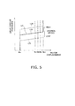
FIG. 5 is a view showing an example of the motor displacement/drive circuit pressure characteristic; -
FIG. 6 is a view showing an example of the vehicle speed/traction force graph for the work vehicle; -
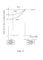
FIG. 7 is a view showing an example of the throttle upper limit map; -
FIG. 8 is a view showing the relationship between the accelerator operation amount and the set throttle opening degree; -
FIG. 9 is a flowchart showing the assessment process in throttle limiting control; -
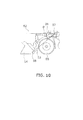
FIG. 10 is a view showing the definition of the boom angle; -
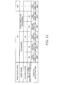
FIG. 11 is a table showing the throttle upper limit map selected for each work phase; -
FIG. 12 is a view showing the output torque curve of the engine when each throttle upper limit map is selected; and -
FIG. 13 is a view showing an example of the output torque curve of the engine in the conventional technique. - A
work vehicle 50 according to an embodiment of the present invention is described hereinafter with reference to the attached drawings.FIG. 1 is a side view of thework vehicle 50. Thework vehicle 50 is a wheel loader. Thework vehicle 50 is provided with avehicle body 51, a work implement 52, a plurality oftires 55, and acab 56. The work implement 52 is installed on a front part of thevehicle body 51. The work implement 52 has aboom 53, abucket 54, alift cylinder 19, and abucket cylinder 26. Theboom 53 is a member for raising thebucket 54. Theboom 53 is driven by thelift cylinder 19. Thebucket 54 is attached to a distal end of theboom 53. Thebucket 54 is dumped and tilted by thebucket cylinder 26. Thecab 56 is disposed above thevehicle body 51. -
FIG. 2 is a block diagram showing the configuration of ahydraulic drive mechanism 30 equipped in thework vehicle 50. Thehydraulic drive mechanism 30 primarily comprises anengine 1, second hydraulic pump 2, acharge pump 3, a firsthydraulic pump 4, a travelhydraulic motor 10, anengine controller 12a, avehicle body controller 12, and a drivehydraulic circuit 20. In thehydraulic drive mechanism 30, the firsthydraulic pump 4 is driven by theengine 1 to discharge hydraulic fluid. The travelhydraulic motor 10 is driven by the hydraulic fluid discharged from the firsthydraulic pump 4. The travelhydraulic motor 10 drives rotation of theabovementioned tires 55, and thework vehicle 50 thereby travels. Specifically, a so-called one-pump one-motor HST system is employed in thehydraulic drive mechanism 30. - The
engine 1 is a diesel engine, and the output torque produced by theengine 1 is transmitted to the second hydraulic pump 2, thecharge pump 3, the firsthydraulic pump 4, and other components. Thehydraulic drive mechanism 30 is provided with anengine speed sensor 1 a for detecting the actual rotation speed of theengine 1. Afuel injection device 1 b is connected to theengine 1. Theengine controller 12a described hereinafter controls the output torque (hereinafter referred to as "engine torque") and rotation speed of theengine 1 by controlling thefuel injection device 1 b in accordance with the set throttle opening degree. - The first
hydraulic pump 4 is driven by theengine 1, and thereby discharges hydraulic fluid. The firsthydraulic pump 4 is a variable-displacement hydraulic pump. The hydraulic fluid discharged from the firsthydraulic pump 4 is sent through the drivehydraulic circuit 20 to the travelhydraulic motor 10. Specifically, the drivehydraulic circuit 20 has afirst drive circuit 20a and asecond drive circuit 20b. Supplying the hydraulic fluid from the firsthydraulic pump 4 to the travelhydraulic motor 10 via thefirst drive circuit 20a causes the travelhydraulic motor 10 to be driven in one direction (e.g., the forward direction). Supplying the hydraulic fluid from the firsthydraulic pump 4 to the travelhydraulic motor 10 via thesecond drive circuit 20b causes the travelhydraulic motor 10 to be driven in the other direction (e.g., the reverse direction). - The drive
hydraulic circuit 20 is provided with a drivecircuit pressure detector 17. The drivecircuit pressure detector 17 detects the pressure (hereinafter referred to as "drive circuit pressure") of the hydraulic fluid that is supplied to the travelhydraulic motor 10 via thefirst drive circuit 20a or thesecond drive circuit 20b. Specifically, the drivecircuit pressure detector 17 has a first drivecircuit pressure sensor 17a and a second drivecircuit pressure sensor 17b. The first drivecircuit pressure sensor 17a detects the hydraulic pressure of thefirst drive circuit 20a. The second drivecircuit pressure sensor 17b detects the hydraulic pressure of thesecond drive circuit 20b. The first drivecircuit pressure sensor 17a and the second drivecircuit pressure sensor 17b send detection signals to thevehicle body controller 12. A pumpdisplacement control cylinder 6 and anFR switch unit 5 for controlling the discharge direction of the firsthydraulic pump 4 are connected to the firsthydraulic pump 4. - The
FR switch unit 5 is an electromagnetic control valve for switching the direction in which hydraulic fluid is supplied to the pumpdisplacement control cylinder 6, on the basis of a control signal from thevehicle body controller 12. TheFR switch unit 5 switches the discharge direction of the firsthydraulic pump 4 by switching the direction in which hydraulic fluid is supplied to the pumpdisplacement control cylinder 6. Specifically, theFR switch unit 5 switches the discharge direction of the firsthydraulic pump 4 between discharge to thefirst drive circuit 20a and discharge to thesecond drive circuit 20b. The pumpdisplacement control cylinder 6 is driven by a supply of hydraulic fluid via apump pilot circuit 32, and thereby changes the tilt angle of the firsthydraulic pump 4. - A pump
displacement control unit 7 is provided in thepump pilot circuit 32. The pumpdisplacement control unit 7 is an electromagnetic control valve that is controlled on the basis of a control signal from thevehicle body controller 12. The pumpdisplacement control unit 7 controls the flow rate of the hydraulic fluid supplied to the pumpdisplacement control cylinder 6 via thepump pilot circuit 32. - The
pump pilot circuit 32 is connected to acharge circuit 33 and a hydraulic fluid tank via acutoff valve 47. A pilot port of thecutoff valve 47 is connected to thefirst drive circuit 20a and thesecond drive circuit 20b via ashuttle valve 46. Theshuttle valve 46 introduces the larger of the hydraulic pressure of thefirst drive circuit 20a and the hydraulic pressure of thesecond drive circuit 20b to the pilot port of thecutoff valve 47. A drive circuit pressure is thereby applied to the pilot port of thecutoff valve 47. Thecutoff valve 47 communicates thecharge circuit 33 and thepump pilot circuit 32 when the drive circuit pressure is lower than a predetermined cutoff pressure. Hydraulic fluid is thereby supplied from thecharge circuit 33 to thepump pilot circuit 32. When the drive circuit pressure is equal to or above the predetermined cutoff pressure, thecutoff valve 47 communicates thepump pilot circuit 32 with the hydraulic fluid tank to allow the hydraulic fluid of thepump pilot circuit 32 to flow to the hydraulic fluid tank. A decrease in the hydraulic pressure of thepump pilot circuit 32 thereby causes the displacement of the firsthydraulic pump 4 to be reduced, and the drive circuit pressure is kept from increasing. - The
charge pump 3 is a pump for supplying hydraulic fluid to the drivehydraulic circuit 20, and is driven by theengine 1. Thecharge pump 3 is connected to thecharge circuit 33. Thecharge pump 3 supplies hydraulic fluid to thepump pilot circuit 32 via thecharge circuit 33. Thecharge circuit 33 is connected to thefirst drive circuit 20a via afirst check valve 41. Thefirst check valve 41 allows the flow of hydraulic fluid from thecharge circuit 33 to thefirst drive circuit 20a, but restricts the flow of hydraulic fluid from thefirst drive circuit 20a to thecharge circuit 33. Thecharge circuit 33 is connected to thesecond drive circuit 20b via asecond check valve 42. Thesecond check valve 42 allows the flow of hydraulic fluid from thecharge circuit 33 to thesecond drive circuit 20b, but restricts the flow of hydraulic fluid from thesecond drive circuit 20b to thecharge circuit 33. Thecharge circuit 33 is connected to thefirst drive circuit 20a via afirst relief valve 43. Thefirst relief valve 43 is opened when the hydraulic pressure in thefirst drive circuit 20a becomes greater than a predetermined pressure. Thecharge circuit 33 is connected to thesecond drive circuit 20b via asecond relief valve 44. Thesecond relief valve 44 is opened when the hydraulic pressure in thesecond drive circuit 20b becomes greater than a predetermined pressure. Thecharge circuit 33 is connected to the hydraulic fluid tank via a low-pressure relief valve 45. The low-pressure relief valve 45 is opened when the hydraulic pressure in thecharge circuit 33 becomes greater than a predetermined relief pressure. The drive circuit pressure is thereby adjusted so as not to exceed the predetermined relief pressure. - The second hydraulic pump 2 is driven by the
engine 1. The hydraulic fluid discharged from the second hydraulic pump 2 is supplied to thelift cylinder 19 via a work implementhydraulic circuit 31. The work implement 52 is thereby driven. The hydraulic fluid discharged from the second hydraulic pump 2 is supplied to a steering cylinder (not shown) via the work implementhydraulic circuit 31. The orientation of thework vehicle 50 is thereby changed. The discharge pressure of the second hydraulic pump 2 is detected by adischarge pressure sensor 39. Thedischarge pressure sensor 39 sends a detection signal to thevehicle body controller 12. The work implementhydraulic circuit 31 is provided with a work implementcontrol valve 18. The work implementcontrol valve 18 is driven in accordance with the operation amount of a work implementoperation member 23. The work implementcontrol valve 18 controls, in accordance with the pilot pressure applied to a pilot port, the flow rate of hydraulic fluid supplied to thelift cylinder 19. The pilot pressure applied to the pilot port of the work implementcontrol valve 18 is controlled by apilot valve 23a of the work implementoperation member 23. Thepilot valve 23a applies a pilot pressure that is in accordance with the operation amount of the work implementoperation member 23 to the pilot port of the work implementcontrol valve 18. Thelift cylinder 19 is thereby controlled in accordance with the operation amount of the work implementoperation member 23. The pilot pressure applied to the pilot port of the work implementcontrol valve 18 is detected by aPPC pressure sensor 21. The pressure of the hydraulic fluid supplied to thelift cylinder 19 is detected by aboom pressure sensor 22. ThePPC pressure sensor 21 and theboom pressure sensor 22 send detection signals to thevehicle body controller 12. Thelift cylinder 19 is provided with aboom angle detector 38. Theboom angle detector 38 detects the boom angle described hereinafter. Theboom angle detector 38 is a sensor for detecting the rotation angle of theboom 53. Alternatively, theboom angle detector 38 may detect the stroke amount of thelift cylinder 19 so that the rotation angle of theboom 53 is calculated from the stroke amount. Theboom angle detector 38 sends a detection signal to thevehicle body controller 12. Thebucket cylinder 26 is also controlled by a control valve in the same manner as thelift cylinder 19, but this control valve is not shown inFIG. 2 . - The travel
hydraulic motor 10 is a variable-displacement hydraulic motor. The travelhydraulic motor 10 is driven by hydraulic fluid discharged from the firsthydraulic pump 4, and generates a drive force used for travel. The travelhydraulic motor 10 is provided with amotor cylinder 11 a and a motordisplacement control unit 11 b. Themotor cylinder 11a changes the tilt angle of the travelhydraulic motor 10. The motordisplacement control unit 11 b is an electromagnetic control valve that is controlled on the basis of a control signal from thevehicle body controller 12. The motordisplacement control unit 11 b controls themotor cylinder 11 a on the basis of a control signal from thevehicle body controller 12. Themotor cylinder 11 a and the motordisplacement control unit 11 b are connected to amotor pilot circuit 34. Themotor pilot circuit 34 is connected to thefirst drive circuit 20a via acheck valve 48. Thecheck valve 48 allows the flow of hydraulic fluid from thefirst drive circuit 20a to themotor pilot circuit 34, but restricts the flow of hydraulic fluid from themotor pilot circuit 34 to thefirst drive circuit 20a. Themotor pilot circuit 34 is connected to thesecond drive circuit 20b via acheck valve 49. Thecheck valve 49 allows the flow of hydraulic fluid from thesecond drive circuit 20b to themotor pilot circuit 34, but restricts the flow of hydraulic fluid from themotor pilot circuit 34 to thesecond drive circuit 20b. The larger of the hydraulic pressure of thefirst drive circuit 20a and the hydraulic pressure of thesecond drive circuit 20b, i.e., the hydraulic fluid at the drive circuit pressure, is supplied to themotor pilot circuit 34 by thecheck valves displacement control unit 11 b switches the supply direction and supply flow rate of hydraulic fluid from themotor pilot circuit 34 to themotor cylinder 11 a on the basis of a control signal from thevehicle body controller 12. Thevehicle body controller 12 can thereby arbitrarily change the displacement of the travelhydraulic motor 10. The maximum displacement and/or minimum displacement of the travelhydraulic motor 10 can also be arbitrarily set. - The
hydraulic drive mechanism 30 is provided with avehicle speed sensor 16. Thevehicle speed sensor 16 detects the vehicle speed. Thevehicle speed sensor 16 sends a vehicle speed signal to thevehicle body controller 12. Thevehicle speed sensor 16 detects the vehicle speed by, for example, detecting the speed of a tire drive shaft. - The
work vehicle 50 is provided with anaccelerator operation member 13a, a forward/reverse switchingoperation member 14, a tractioncontrol selection member 15, and an inchingoperation unit 27. - The
accelerator operation member 13a is a member for enabling the operator to set the throttle opening degree. Theaccelerator operation member 13a is an example of the throttle opening degree setting unit of the present invention. Theaccelerator operation member 13a is an accelerator pedal, for example, operated by the operator. Theaccelerator operation member 13a is connected to an acceleratoroperation amount sensor 13. The acceleratoroperation amount sensor 13 is composed of a potentiometer or the like. The acceleratoroperation amount sensor 13 sends an opening degree signal indicating the accelerator operation amount of theaccelerator operation member 13a to theengine controller 12a. The operator can control the speed of theengine 1 by adjusting the accelerator operation amount. - The forward/reverse switching
operation member 14 operated by the operator is switched to a forward position, a reverse position, or a neutral position. The forward/reverse switchingoperation member 14 sends an operation signal indicating the position of the forward/reverse switchingoperation member 14 to thevehicle body controller 12. The operator can switch between forward and reverse travel of thework vehicle 50 by operating the forward/reverse switchingoperation member 14. - The traction
control selection member 15 is a dial-type switch, for example. The tractioncontrol selection member 15 is operated by the operator to set the maximum traction force produced by the traction control described hereinafter. The tractioncontrol selection member 15 sends an operation signal indicating the selection position of the tractioncontrol selection member 15 to thevehicle body controller 12. - The inching
operation unit 27 has an inchingoperation member 27a and an inchingoperation sensor 27b. The inchingoperation member 27a is operated by the operator. The inchingoperation member 27a is a pedal, for example. The inchingoperation member 27a functions both in inching operation and braking operation, as described hereinafter. The inchingoperation sensor 27b detects the operation amount of the inchingoperation member 27a and transmits a detection signal to thevehicle body controller 12. When the inchingoperation member 27a is operated, thevehicle body controller 12 controls the pumpdisplacement control unit 7 on the basis of the detection signal from the inchingoperation sensor 27b. Thevehicle body controller 12 reduces the hydraulic pressure of thepump pilot circuit 32 in accordance with the operation amount of the inchingoperation member 27a. The inchingoperation unit 27 is used in such cases as when, for example, the operator wishes to increase the speed of theengine 1 while keeping the travel speed from increasing. Specifically, when the speed of theengine 1 is increased by an operation of theaccelerator operation member 13a, the hydraulic pressure of thepump pilot circuit 32 also increases. At this time, the increase in the hydraulic pressure of thepump pilot circuit 32 can be controlled by operating the inchingoperation member 27a. The displacement of the firsthydraulic pump 4 can thereby be kept from increasing, and the speed of the travelhydraulic motor 10 can be kept from increasing. - A
brake valve 28 is linked to the inchingoperation member 27a. Thebrake valve 28 controls the supply of hydraulic fluid to ahydraulic brake device 29. The inchingoperation member 27a serves also as an operation member for thehydraulic brake device 29. Until the operation amount of the inchingoperation member 27a reaches a predetermined amount, only the inching operation described above is performed on the basis of the detection signal from the inchingoperation sensor 27b. When the operation amount of the inchingoperation member 27a reaches the predetermined amount, thebrake valve 28 begins operating, and a braking force is thereby generated in thehydraulic brake device 29. The braking force of thehydraulic brake device 29 is controlled in accordance with the operation amount of the inchingoperation member 27a while the operation amount of the inchingoperation member 27a is equal to or greater than the predetermined amount. - The
engine controller 12a is a CPU or other computing device and/or an electronic control unit having a memory and various other components. Theengine controller 12a is an example of the second control unit of the present invention. Theengine controller 12a controls theengine 1 so that a target engine speed that is in accordance with the set throttle opening degree is obtained. The output torque curve for theengine 1 is shown inFIG. 3 . The output torque curve of theengine 1 indicates the relationship between the speed of theengine 1 and the magnitude of the maximum engine torque that can be output by theengine 1 at each engine speed. InFIG. 3 , the solid line L100 is the engine output torque curve when the accelerator operation amount is 100% in a state (hereinafter referred to as "normal state") in which the control described hereinafter for setting the upper limit of the throttle opening degree is not performed. This engine output torque curve corresponds to, e.g., the rated or maximum power output of theengine 1. For the accelerator operation amount to be 100% means that theaccelerator operation member 13a is being operated to the maximum limit thereof. The broken line L75 indicates the engine output torque curve when the accelerator operation amount is 75% in the normal state. Theengine controller 12a controls the output of theengine 1 so that the engine torque is equal to or less than the engine output torque curve. The output of theengine 1 here is controlled by, for example, controlling the upper limit value of the amount of fuel injected to theengine 1. - The
vehicle body controller 12 is a CPU or other computing device and/or an electronic control unit having a memory and various other components. Thevehicle body controller 12 is an example of the first control unit of the present invention. Thevehicle body controller 12 controls the displacement of the firsthydraulic pump 4 and the displacement of the travelhydraulic motor 10 by electronically controlling various control valves on the basis of the output signals from the various detectors. - Specifically, the
vehicle body controller 12 outputs a command signal to the pumpdisplacement control unit 7 on the basis of the engine speed detected by theengine speed sensor 1 a. The relationship between the pump displacement and the drive circuit pressure is thereby specified.FIG. 4 shows an example of the pump displacement/drive circuit pressure characteristic. The pump displacement/drive circuit pressure characteristic indicates the relationship between the pump displacement and the drive circuit pressure. InFIG. 4 , L11 through L16 are lines indicating the pump displacement/drive circuit pressure characteristic that is changed in accordance with the engine speed. Specifically, the pump displacement/drive circuit pressure characteristic changes to L11 through L16 by the control of the flow rate of the pumpdisplacement control unit 7 by thevehicle body controller 12 on the basis of the engine speed. The pump displacement is thereby controlled so as to correspond to the engine speed and the drive circuit pressure. - The
vehicle body controller 12 processes output signals from theengine speed sensor 1a and the drivecircuit pressure detector 17 and outputs a command signal for the motor displacement to the motordisplacement control unit 11 b. Here, thevehicle body controller 12 references the motor displacement/drive circuit pressure characteristic stored in thevehicle body controller 12 and sets the motor displacement from the values of the engine speed and drive circuit pressure. Thevehicle body controller 12 outputs a command to change to a tilt angle that corresponds to the set motor displacement to the motordisplacement control unit 11 b.FIG. 5 shows an example of the motor displacement/drive circuit pressure characteristic. The solid line L21 inFIG. 5 is a line determining the motor displacement with respect to the drive circuit pressure when the engine speed is a certain value. The motor displacement in this case corresponds to the tilt angle of the travelhydraulic motor 10. The tilt angle is at minimum (Min) until the drive circuit pressure is equal to or less than a certain value. The tilt angle then also gradually increases (inclined portion L22 of the solid line) as the drive circuit pressure increases. After the tilt angle has reached maximum (Max), the tilt angle remains at the maximum tilt angle Max despite further increasing of the drive circuit pressure. The inclined portion L22 specifies the target pressure for the drive circuit pressure. Specifically, thevehicle body controller 12 increases the displacement of the travel hydraulic motor when the drive circuit pressure becomes larger than the target pressure. When the drive circuit pressure becomes smaller than the target pressure, the displacement of the travel hydraulic motor is reduced. The target pressure is determined according to the engine speed. Specifically, the inclined portion L22 shown inFIG. 5 is set so as to rise or fall in response to an increase or decrease of the engine speed. Specifically, control is performed so that when the engine speed is low, the tilt angle of the inclined portion L22 increases from a state in which the drive circuit pressure is lower, and the tilt angle reaches the maximum thereof in the state in which the drive circuit pressure is lower (see the dashed-line inclined portion L23 at the bottom inFIG. 5 ). Conversely, when the engine speed is high, control is performed so that the minimum tilt angle Min is maintained until the drive circuit pressure reaches a higher value, and the maximum tilt angle Max is reached in the state in which the drive circuit pressure is higher (see the dashed-line inclined portion L24 at the top inFIG. 5 ). The traction force and vehicle speed of the work vehicle are thereby varied in non-stage fashion, as shown inFIG. 6 , and the vehicle speed can be automatically varied from zero to the maximum speed without a shifting operation. - The
vehicle body controller 12 executes traction control in response to operation of the tractioncontrol selection member 15. Traction control is control for varying the maximum traction force of the vehicle through a plurality of stages by changing the maximum displacement of the travelhydraulic motor 10. Thevehicle body controller 12 reduces the maximum displacement of the travelhydraulic motor 10 through a plurality of stages in response to operation of the tractioncontrol selection member 15. Specifically, as shown inFIG. 5 , thevehicle body controller 12 outputs command signals to the motordisplacement control unit 11 b to change the maximum displacement from Max to Ma, Mb, or Mc. When the maximum displacement is changed to Ma, the vehicle speed/traction force characteristic varies according to the line La inFIG. 6 . The maximum traction force thus decreases relative to the line L1 indicating the vehicle speed/traction force characteristic for the state in which traction control is not performed. When the maximum displacement is changed to Mb, the vehicle speed/traction force characteristic varies according to the line Lb, and the maximum traction force is further reduced. When the maximum displacement is changed to Mc, the vehicle speed/traction force characteristic varies according to the line Lc, and the maximum traction force is further reduced. - The
vehicle body controller 12 performs control (hereinafter referred to as "throttle limiting control") for distinguishing the work phase of the work implement 52 and setting the upper limit of the throttle opening degree in accordance with the distinguished work phase. Theengine controller 12a described above controls the output of the engine on the basis of the smaller of the throttle opening degree set by operation of theaccelerator operation member 13a and the upper limit of the throttle opening degree set by thevehicle body controller 12. Throttle limiting control is described in detail hereinafter. - The
vehicle body controller 12 sets the upper limit of the throttle opening degree on the basis of the throttle upper limit map shown inFIG. 7 . The throttle upper limit map specifies the upper limit of the throttle opening degree with respect to the vehicle speed. The throttle upper limit map is an example of the throttle upper limit information of the present invention. As shown inFIG. 7 , the throttle upper limit map includes a first throttle upper limit map Map1, a second throttle upper limit map Map2, and a third throttle upper limit map Map3. In the first throttle upper limit map Map1, the upper limit of the throttle opening degree is fixed at an opening degree Th1 irrespective of the vehicle speed. The opening degree Th1 matches the throttle opening degree when the accelerator operation amount is 100% in the normal state. Specifically, selecting the first throttle upper limit map Map1 means that an upper limit is not set for the throttle opening degree. - The second throttle upper limit map Map2 specifies an upper limit for the throttle opening degree that is lower than that of the first throttle upper limit map Map1 with respect to the vehicle speed. The third throttle upper limit map Map3 specifies an upper limit for the throttle opening degree that is lower than that of the second throttle upper limit map Map2 with respect to the vehicle speed. The second throttle upper limit map Map2 includes a characteristic whereby the upper limit of the throttle opening degree gradually increases in accordance with an increase in vehicle speed. The third throttle upper limit map Map3 includes a characteristic whereby the upper limit of the throttle opening degree gradually increases in accordance with an increase in vehicle speed. Specifically, in the second throttle upper limit map Map2, when the vehicle speed varies within the range from v1 to v2, the throttle opening degree increases in accordance with an increase in vehicle speed. In the third throttle upper limit map Map3, when the vehicle speed varies within the range from v1 to v2, the throttle opening degree increases in accordance with an increase in vehicle speed.
- In the second throttle upper limit map Map2, the throttle opening degree is fixed at an opening degree Th2 when the vehicle speed is less than v1. In the third throttle upper limit map Map3, the throttle opening degree is fixed at an opening degree Th3 when the vehicle speed is less than v1. The opening degree Th3 is less than the opening degree Th2.
FIG. 8(a) shows the relationship between the accelerator operation amount and the set throttle opening degree during low-speed travel in which the vehicle speed is less than v1. InFIG. 8(a) , "Lv1" indicates the relationship between the accelerator operation amount and the set throttle opening degree when the first throttle upper limit map Map1 is selected during low-speed travel. "Lv2" indicates the relationship between the accelerator operation amount and the set throttle opening degree when the second throttle upper limit map Map2 is selected during low-speed travel. "Lv3" indicates the relationship between the accelerator operation amount and the set throttle opening degree when the third throttle upper limit map Map3 is selected during low-speed travel. As shown inFIG. 8(a) , the throttle opening degree is set to a large value in response to an increase in the accelerator operation amount. However, when the first throttle upper limit map Map1 is selected, the opening degree Th1 becomes the upper limit of the throttle opening degree. When the second throttle upper limit map Map2 is selected, the opening degree Th2 becomes the upper limit of the throttle opening degree. When the third throttle upper limit map Map3 is selected, the opening degree Th3 becomes the upper limit of the throttle opening degree. - As shown in
FIG. 7 , in the second throttle upper limit map Map2, the throttle opening degree is fixed at the opening degree Th1 when the vehicle speed is greater than v2. In the third throttle upper limit map Map3 as well, the throttle opening degree is fixed at the opening degree Th1 when the vehicle speed is greater than v2. In other words, whether the second throttle upper limit map Map2 or the third throttle upper limit map Map3 is selected, thevehicle body controller 12 does not set an upper limit for the throttle opening degree when the vehicle speed is greater than v2.FIG. 8(b) shows the relationship between the accelerator operation amount and the set throttle opening degree during high-speed travel in which the vehicle speed is greater than v2. InFIG. 8(b) , "Hv1" indicates the relationship between the accelerator operation amount and the set throttle opening degree when the first throttle upper limit map Map1 is selected during high-speed travel. "Hv2" indicates the relationship between the accelerator operation amount and the set throttle opening degree when the second throttle upper limit map Map2 is selected during high-speed travel. "Hv3" indicates the relationship between the accelerator operation amount and the set throttle opening degree when the third throttle upper limit map Map3 is selected during high-speed travel. As shown inFIG. 8(b) , a throttle opening degree that is in accordance with the accelerator operation amount is set regardless of which of the first through third throttle upper limit maps Map1 through Map3 is set. The opening degree Th1 becomes the upper limit of the throttle opening degree. - The conditions for selecting the first through third throttle upper limit maps Map1 through Map3 in throttle limiting control will next be described.
FIG. 9 is a flowchart showing the assessment process in throttle limiting control. In the first step S1, an assessment is made as to whether traction control is being performed. On the basis of an operation signal from the tractioncontrol selection member 15, thevehicle body controller 12 assesses whether traction control is being performed. When traction control is not being performed, the first throttle upper limit map Map1 is selected in step S6. When traction control is being performed, the process proceeds to step S2. - In step S2, an assessment is made as to whether an excavation flag is "ON." For the excavation flag to be "ON" means that the work phase is in a state of excavation. Specifically, the excavation flag is set to "ON" when condition 1-1 or condition 1-2 below is satisfied, and condition 1-3 and condition 1-4 are satisfied.
- Condition 1-1 is that a boom bottom pressure lower than a predetermined reference boom bottom pressure has been detected continuously for a predetermined time or longer in a case in which the boom angle is equal to or greater than a predetermined angle threshold and is less than zero degrees. As shown in
FIG. 10 , the boom angle is the angle θ between the horizontal direction, which is zero degrees, and a line connecting aboom pin 57 and abucket pin 58 as viewed from the side. Angles below the horizontal direction have negative values, and angles higher than the horizontal direction have positive values. The boom angle is defined so as to increase in the upward direction. The predetermined angle threshold corresponds to the boom angle at which the work implement 52 is positioned on the ground surface. The boom bottom pressure is detected by theboom pressure sensor 22. The predetermined reference boom bottom pressure is specified in relation to the boom angle, and the reference boom bottom pressure also generally increases as the boom angle increases. The predetermined time is set to an extremely small value, such as one second. - Condition 1-2 is that a boom bottom pressure lower than the reference boom bottom pressure when the boom angle is zero degrees is detected continuously for a predetermined time or longer in a case in which the boom angle is zero degrees or greater. The predetermined time is set to an extremely small value, such as one second.
- Condition 1-3 is that the boom bottom pressure is equal to or greater than a predetermined boom bottom pressure threshold. The predetermined boom bottom pressure threshold corresponds to the boom bottom pressure in a state in which the work implement 52 is positioned on the ground surface.
- Condition 1-4 is that the boom angle is equal to or less than a predetermined boom angle threshold. The boom angle threshold is set to a value less than zero degrees that may occur during excavation work.
- In step S2, when the excavation flag is assessed to be "ON," the process proceeds to step S3. The excavation flag is set to "OFF" when condition 1-1' or condition 1-2' described below is satisfied.
- Condition 1-1' is that the boom bottom pressure reduction flag is "ON." The boom bottom pressure reduction flag is set to "ON" when condition 1-1 or condition 1-2 described above is satisfied.
- Condition 1-2' is that the forward/reverse switching
operation member 14 is at a position other than the forward position; i.e., the forward/reverse switchingoperation member 14 is at the reverse position or the neutral position. - In step S3, an assessment is made as to whether a scooping flag is "ON." For the scooping flag to be "ON" means that a scooping operation is being performed. Specifically, the scooping flag is set to "ON" when condition 2-1 and condition 2-2 described below are satisfied.
- Condition 2-1 is that the abovementioned excavation flag is "ON."
- Condition 2-2 is that the boom angle is greater than the abovementioned predetermined boom angle threshold.
- In step S3, when the scooping flag is assessed to be "ON," the first throttle upper limit map Map1 is selected in step S7. When the scooping flag is assessed to not be "ON" in step S3, the process proceeds to step S4.
- In step S4, an assessment is made as to whether a work implement/inching assessment is "ON." For the work implement/inching assessment to be "ON" means that the work implement 52 or the inching function is being used. Specifically, the work implement/inching assessment is set to "ON" when condition 3-1, 3-2, or 3-3 described below is satisfied.
- Condition 3-1 is that the discharge pressure of the second hydraulic pump is greater than a predetermined first discharge pressure threshold. The value set for the predetermined first discharge pressure threshold is one that can occur when the work implement 52 or a steering cylinder (not shown) is being used.
- Condition 3-2 is that the boom raising PPC pressure is greater than a predetermined first pilot pressure threshold. The boom raising PPC pressure is the pilot pressure outputted from the work implement
operation member 23 during an operation (hereinafter referred to as "boom-raising operation") for elevating theboom 53. The value set for the predetermined first pilot pressure threshold is one that can occur when the work implementoperation member 23 is being operated to raise the boom. - Condition 3-3 is that the operation amount of the inching
operation member 27a is greater than a predetermined first inching operation threshold. The value set for the predetermined first inching operation threshold is one that can occur when the inchingoperation member 27a is being operated. - In step S4, when the work implement/inching assessment is assessed to be "ON," the second throttle upper limit map Map2 is selected in step S8. When the work implement/inching assessment is assessed to not be "ON" in step S4, the third throttle upper limit map Map3 is selected in step S9.
- The work implement/inching assessment is set to "OFF" when conditions 3-1', 3-2', and 3-3' described below are satisfied.
- Condition 3-1' is that the discharge pressure of the second hydraulic pump is less than a predetermined second discharge pressure threshold. The predetermined second discharge pressure threshold is less than the first discharge pressure threshold. The value set for the predetermined second discharge pressure threshold is one that may indicate that the work implement 52 or the steering cylinder (not shown) is not being used.
- Condition 3-2' is that the boom raising PPC pressure is less than a predetermined second pilot pressure threshold. The predetermined second pilot pressure threshold is less than the first pilot pressure threshold. The value set for the predetermined second pilot pressure threshold is one that may indicate that the work implement
operation member 23 is not being operated to raise the boom. Specifically, even when the boom raising PPC pressure is not zero, condition 3-2' is assessed to be satisfied when the boom raising PPC pressure is small enough to indicate that the work implementoperation member 23 is not being operated to raise the boom. - Condition 3-3' is that the operation amount of the inching
operation member 27a is less than a predetermined second inching operation threshold. The value set for the predetermined second inching operation threshold is one that may indicate that the inchingoperation member 27a is not being operated. Specifically, even when the operation amount of the inchingoperation member 27a is not zero, condition 3-3' is assessed to be satisfied when the operation amount of the inchingoperation member 27a is small enough to indicate that the inchingoperation member 27a is not being operated. - When the excavation flag is assessed to not be "ON" in step S2, the process proceeds to step S5. In step S5, an assessment is made as to whether the work implement/inching assessment is "ON," in the same manner as in step S4. When the work implement/inching assessment is assessed to be "ON," the first throttle upper limit map Map1 is selected in step S6. When the work implement/inching assessment is assessed to not be "ON," the second throttle upper limit map Map2 is selected in step S10.
- As described above, the throttle upper limit map that is appropriate according to the current work phase is selected in the
work vehicle 50 according to the present embodiment.FIG. 11 is a table showing the throttle upper limit map selected for each work phase. As shown inFIG. 11 , when traction control is not being performed, different throttle upper limit maps are selected according to whether the work phase is excavation or work other than excavation. In an instance in which the usage conditions for the work implement or the inching function are the same, when the work phase is excavation, a throttle upper limit map is selected in which the upper limit of the throttle opening degree is less than that of a work phase other than excavation. Consequently, when the work phase is excavation, the upper limit of the throttle opening degree is reduced to a value less than that of a work phase other than excavation. The output of theengine 1 is thereby restrained.FIG. 12 shows the output torque curve of theengine 1 when each throttle upper limit map Map1 through Map3 is selected. Specifically,FIG. 12(a) shows the output torque curve of theengine 1 when the first throttle upper limit map Map1 is selected.FIG. 12(b) shows the output torque curve of theengine 1 when the second throttle upper limit map Map2 is selected.FIG. 12(c) shows the output torque curve of theengine 1 when the third throttle upper limit map Map3 is selected. As shown inFIG. 12 , the maximum value Nmax2 that occurs for the engine speed when the second throttle upper limit map Map2 is selected is less than the maximum value Nmax1 that occurs when the first throttle upper limit map Map1 is selected. Moreover, the maximum value Nmax3 that occurs for the engine speed when the third throttle upper limit map Map3 is selected is less than the maximum value Nmax2 that occurs when the second throttle upper limit map Map2 is selected. Engine fuel economy can thus be enhanced by restraining the output of the engine. There is no need for a high flow rate to the travelhydraulic motor 10 when the work phase is excavation. Reducing the upper limit of the throttle opening degree therefore has minimal effect on travel characteristics. As described above, the second throttle upper limit map Map2 and the third throttle upper limit map Map3 have characteristics whereby the upper limit of the throttle opening degree gradually increases in accordance with an increase in vehicle speed. Sharp variations in the throttle opening degree are therefore suppressed. It is thereby possible to suppress shocks produced in the work vehicle. Furthermore, in the second throttle upper limit map Map2 and the third throttle upper limit map Map3, the upper limit of the throttle opening degree is fixed at Th1 when the vehicle speed is greater than the predetermined speed v2. Specifically, thevehicle body controller 12 does not set an upper limit for the throttle opening degree when the vehicle speed is greater than the predetermined speed v2. Adverse effects on travel characteristics during high-speed travel can thereby be suppressed. - When the work phase is the same, during use of the work implement 52 or the inching function, a throttle upper limit map is selected in which the upper limit of the throttle opening degree is greater than the value thereof that occurs when the work implement 52 or the inching function is not in use. Consequently, when the work implement 52 or the inching function is in use, the upper limit of the throttle opening degree is increased to a value higher than the value thereof when the work implement 52 or the inching function is not in use. Ease of operation is therefore kept from decreasing.
- The first throttle upper limit map Map1 is selected during scooping work. Specifically, an upper limit is not set for the throttle opening degree during scooping work. A large load is placed on the
lift cylinder 19 during scooping work. Therefore, by selecting the first throttle upper limit map Map1 during scooping work, ease of operation is kept from decreasing. - The first throttle upper limit map Map1 is selected when traction control is not being performed. Specifically, an upper limit is not set for the throttle opening degree when traction control is not being performed. The operator usually turns off the traction control during work in which a large traction force is required. Consequently, since the first throttle upper limit map Map1 is selected when traction control is not being performed, ease of operation can be kept from decreasing.
- An embodiment of the present embodiment is described above, but the present invention is not limited by the above embodiment, and various modifications to this embodiment are possible within the intended scope of the invention.
- In the above embodiment, an example is described in which the work vehicle to which the present invention is applied is a wheel loader. However, the present invention is not limited to this configuration. For example, the present invention may also be applied to other work vehicles equipped with an HST.
- In the above embodiment, an example is described of a
work vehicle 50 equipped with a one-pump one-motor HST system that includes one hydraulic pump and one travelhydraulic motor 10. However, the present invention is not limited to this configuration. For example, the present invention may also be applied to a work vehicle equipped with a one-pump two-motor HST system that includes one first hydraulic pump and two travel hydraulic motors. - In the above embodiment, the upper limit of the throttle opening degree is reduced when the work phase is excavation. However, the upper limit of the throttle opening degree may be reduced when the work phase is a predetermined work other than excavation. The predetermined work is preferably work in which the load on the travel hydraulic motor is small.
- In the above embodiment, the inching
operation member 27a serves also as a brake pedal. However, the inching operation member may also be provided as a separate member from the brake pedal. - In the above embodiment, throttle upper limit maps are used as the throttle upper limit information. However, the throttle upper limit information is not limited to being in the form of a map, and may be configured in another format such as a table or an arithmetic expression.
- The present invention makes it possible to provide a work vehicle and method for controlling a work vehicle whereby fuel economy can be enhanced with minimal reduction in travel characteristics or ease of operation of the work vehicle.
-
- 1
- engine
- 2
- second hydraulic pump
- 4
- first hydraulic pump
- 10
- travel hydraulic motor
- 12
- vehicle body controller
- 12a
- engine controller
- 13a
- accelerator operation member
- 27a
- inching operation member
- 50
- work vehicle
- 52
- work implement
- 53
- boom
- 54
- bucket
Claims (9)
- A work vehicle comprising:an engine;a throttle opening degree setting unit for setting a throttle opening degree of the engine;a first hydraulic pump driven by the engine;a travel hydraulic motor driven by hydraulic fluid discharged from the first hydraulic pump;a second hydraulic pump driven by the engine;a work implement driven by hydraulic fluid discharged from the second hydraulic pump;a first control unit for discriminating a work phase of the work implement and setting an upper limit for the throttle opening degree in accordance with the discriminated work phase; anda second control unit for controlling output of the engine on the basis of the smaller of the throttle opening degree set by the throttle opening degree setting unit and the throttle opening degree set by the first control unit.
- The work vehicle according to claim 1, wherein
the first control unit reduces the upper limit of the throttle opening degree when the work phase is assessed to be excavation work. - The work vehicle according to claim 2, wherein
the work implement has a bucket and a boom for supporting the bucket; and the first control unit does not reduce the upper limit of the throttle opening degree when the angle in a longitudinal direction of the boom, defined so that the value thereof increases upward, is equal to or greater than a predetermined angle, even when the work phase is assessed to be the excavation work. - The work vehicle according to claim 1, wherein
the first control unit assesses whether the work implement is in use, and when the work implement is in use, the first control unit increases the upper limit of the throttle opening degree to a value higher than the value thereof when the work implement is not in use. - The work vehicle according to claim 1, wherein
the first control unit sets the upper limit of the throttle opening degree on the basis of throttle upper limit information for specifying the upper limit of the throttle opening degree with respect to vehicle speed;
the throttle upper limit information includes first throttle upper limit information, and second throttle upper limit information for specifying a lower upper limit for the throttle opening degree with respect to the vehicle speed than the first throttle upper limit information; and
the first control unit sets the upper limit of the throttle opening degree on the basis of the first throttle upper limit information when the work phase is assessed to be a predetermined first work, and sets the upper limit of the throttle opening degree on the basis of the second throttle upper limit information when the work phase is assessed to be a predetermined second work having a smaller load than the first work. - The work vehicle according to claim 5, wherein
the throttle upper limit information includes a characteristic whereby the upper limit of the throttle opening degree gradually increases in accordance with an increase in vehicle speed. - The work vehicle according to claim 1, wherein
the first control unit does not set an upper limit for the throttle opening degree when the vehicle speed is greater than a predetermined speed. - The work vehicle according to any of claims 1 through 7, further comprising:an inching operation member for reducing the vehicle speed; whereinthe first control unit assesses whether the inching operation member is in use, and when the inching operation member is in use, the first control unit increases the upper limit of the throttle opening degree to a value higher than the value thereof when the inching operation member is not in use.
- A method for controlling a work vehicle comprising an engine, a throttle opening degree setting unit for setting a throttle opening degree of the engine, a first hydraulic pump driven by the engine, a travel hydraulic motor driven by hydraulic fluid discharged from the first hydraulic pump, a second hydraulic pump driven by the engine, and a work implement driven by hydraulic fluid discharged from the second hydraulic pump; the method comprising:a step of discriminating a work phase of the work implement;a step of setting an upper limit for the throttle opening degree in accordance with the discriminated work phase; anda step of controlling output of the engine on the basis of the smaller of the throttle opening degree set by the throttle opening degree setting unit and the throttle opening degree set by the first control unit.
Applications Claiming Priority (2)
| Application Number | Priority Date | Filing Date | Title |
|---|---|---|---|
| JP2012058569A JP5106694B1 (en) | 2012-03-15 | 2012-03-15 | Work vehicle and control method of work vehicle |
| PCT/JP2012/062162 WO2013136537A1 (en) | 2012-03-15 | 2012-05-11 | Work vehicle and method for controlling work vehicle |
Publications (3)
| Publication Number | Publication Date |
|---|---|
| EP2792873A4 EP2792873A4 (en) | 2014-10-22 |
| EP2792873A1 true EP2792873A1 (en) | 2014-10-22 |
| EP2792873B1 EP2792873B1 (en) | 2016-10-12 |
Family
ID=47528548
Family Applications (1)
| Application Number | Title | Priority Date | Filing Date |
|---|---|---|---|
| EP12784409.0A Active EP2792873B1 (en) | 2012-03-15 | 2012-05-11 | Work vehicle and method for controlling work vehicle |
Country Status (5)
| Country | Link |
|---|---|
| US (2) | US8666610B2 (en) |
| EP (1) | EP2792873B1 (en) |
| JP (1) | JP5106694B1 (en) |
| CN (1) | CN102985306B (en) |
| WO (1) | WO2013136537A1 (en) |
Cited By (2)
| Publication number | Priority date | Publication date | Assignee | Title |
|---|---|---|---|---|
| US10815925B2 (en) | 2017-04-12 | 2020-10-27 | Toyota Jidosha Kabushiki Kaisha | Vehicle and control method for vehicle |
| EP3492663A4 (en) * | 2017-09-29 | 2020-11-04 | Hitachi Construction Machinery Co., Ltd. | WHEEL LOADER |
Families Citing this family (20)
| Publication number | Priority date | Publication date | Assignee | Title |
|---|---|---|---|---|
| US9046895B2 (en) * | 2009-12-30 | 2015-06-02 | Caterpillar Inc. | System and method for controlling fluid delivery |
| JP5222895B2 (en) * | 2010-05-07 | 2013-06-26 | 株式会社小松製作所 | Work vehicle and control method of work vehicle |
| JP5106694B1 (en) * | 2012-03-15 | 2012-12-26 | 株式会社小松製作所 | Work vehicle and control method of work vehicle |
| US9102372B2 (en) * | 2012-07-24 | 2015-08-11 | Caterpillar Inc. | Track drive system and method |
| JP5192601B1 (en) * | 2012-08-20 | 2013-05-08 | 株式会社小松製作所 | Work vehicle and control method of work vehicle |
| JP6368495B2 (en) * | 2014-01-29 | 2018-08-01 | 株式会社小松製作所 | Work vehicle and control method thereof |
| JP6438368B2 (en) * | 2015-09-18 | 2018-12-12 | ヤンマー株式会社 | Work vehicle |
| JP2017082734A (en) * | 2015-10-30 | 2017-05-18 | 株式会社タダノ | Work vehicle |
| US10151331B2 (en) * | 2015-12-15 | 2018-12-11 | Deere & Company | Electronic begin of regulation control for a hydraulic motor |
| US10059341B2 (en) | 2016-06-17 | 2018-08-28 | Caterpillar Inc. | Control strategy for reduced fuel consumption in machine and powertrain system with same |
| JP6555592B2 (en) * | 2016-09-28 | 2019-08-07 | 日立建機株式会社 | Work vehicle |
| JP7038516B2 (en) * | 2017-09-29 | 2022-03-18 | 日立建機株式会社 | Wheel loader |
| WO2020065913A1 (en) * | 2018-09-28 | 2020-04-02 | 日立建機株式会社 | Cargo work vehicle |
| JP7146701B2 (en) * | 2019-06-27 | 2022-10-04 | 日立建機株式会社 | excavator |
| CN110761906A (en) * | 2019-08-23 | 2020-02-07 | 杜福银 | Control method for improving fuel efficiency of engine |
| KR102924795B1 (en) * | 2019-09-19 | 2026-02-06 | 두산 밥캣 노스 아메리카, 인크. | Drive motor displacement control |
| US11511743B2 (en) * | 2019-12-17 | 2022-11-29 | Cnh Industrial Canada, Ltd. | System and method for controlling the speed of a work vehicle towing an implement |
| CN114233487B (en) * | 2021-11-23 | 2024-07-26 | 湖南道依茨动力有限公司 | Engine control method, engine control device, readable storage medium, and work vehicle |
| JP2024059231A (en) * | 2022-10-18 | 2024-05-01 | 株式会社小松製作所 | Work machine, and method for controlling work machine |
| US20260015820A1 (en) * | 2024-07-09 | 2026-01-15 | Deere & Company | Adaptive eco mode |
Family Cites Families (19)
| Publication number | Priority date | Publication date | Assignee | Title |
|---|---|---|---|---|
| JPH0762450B2 (en) * | 1986-06-26 | 1995-07-05 | トヨタ自動車株式会社 | Slot valve control device for internal combustion engine |
| JP3836587B2 (en) * | 1997-12-01 | 2006-10-25 | 三菱電機株式会社 | Vehicle deceleration control device |
| JP2864241B2 (en) * | 1997-12-22 | 1999-03-03 | 株式会社小松製作所 | Control equipment for construction machinery |
| DE10256923B4 (en) * | 2002-12-05 | 2013-10-24 | Liebherr-France S.A. | Method and device for motion damping of hydraulic cylinders of mobile machines |
| DE112004000751B4 (en) * | 2003-05-07 | 2012-11-15 | Komatsu Ltd. | Work machine with engine control device |
| CN1846047B (en) * | 2003-09-02 | 2010-12-01 | 株式会社小松制作所 | Engine control device |
| KR101116116B1 (en) * | 2003-10-31 | 2012-04-10 | 가부시키가이샤 고마쓰 세이사쿠쇼 | Engine output controller |
| EP1820908B1 (en) * | 2004-12-10 | 2014-10-08 | Komatsu Ltd. | Prime mover control for a construction machine |
| US7390282B2 (en) * | 2005-01-12 | 2008-06-24 | Caterpillar Inc. | Directional shift in hydrostatic drive work machine |
| JP4787831B2 (en) * | 2005-07-22 | 2011-10-05 | 日立建機株式会社 | Shift control device for work vehicle |
| JP4800735B2 (en) * | 2005-10-14 | 2011-10-26 | 株式会社小松製作所 | Engine speed control device for work vehicle |
| RU2390679C2 (en) * | 2005-12-26 | 2010-05-27 | Комацу Лтд. | Building vehicle |
| JP5134238B2 (en) * | 2006-12-15 | 2013-01-30 | 株式会社小松製作所 | Engine load control device for work vehicle |
| JP5264091B2 (en) * | 2007-03-09 | 2013-08-14 | カヤバ工業株式会社 | Automotive throttle throttle control system |
| JP5074086B2 (en) | 2007-04-26 | 2012-11-14 | 株式会社小松製作所 | Construction vehicle |
| US7472684B1 (en) * | 2007-11-14 | 2009-01-06 | Cnh America Llc | High low engine speed cruise control |
| JP5205408B2 (en) * | 2010-03-24 | 2013-06-05 | 株式会社小松製作所 | Work vehicle and control method of work vehicle |
| JP5222895B2 (en) * | 2010-05-07 | 2013-06-26 | 株式会社小松製作所 | Work vehicle and control method of work vehicle |
| JP5106694B1 (en) * | 2012-03-15 | 2012-12-26 | 株式会社小松製作所 | Work vehicle and control method of work vehicle |
-
2012
- 2012-03-15 JP JP2012058569A patent/JP5106694B1/en active Active
- 2012-05-11 US US13/583,861 patent/US8666610B2/en active Active
- 2012-05-11 WO PCT/JP2012/062162 patent/WO2013136537A1/en not_active Ceased
- 2012-05-11 CN CN201280001340.5A patent/CN102985306B/en not_active Expired - Fee Related
- 2012-05-11 EP EP12784409.0A patent/EP2792873B1/en active Active
-
2014
- 2014-01-27 US US14/164,745 patent/US9133862B2/en active Active
Cited By (3)
| Publication number | Priority date | Publication date | Assignee | Title |
|---|---|---|---|---|
| US10815925B2 (en) | 2017-04-12 | 2020-10-27 | Toyota Jidosha Kabushiki Kaisha | Vehicle and control method for vehicle |
| EP3492663A4 (en) * | 2017-09-29 | 2020-11-04 | Hitachi Construction Machinery Co., Ltd. | WHEEL LOADER |
| US11242672B2 (en) | 2017-09-29 | 2022-02-08 | Hitachi Construction Machinery Co., Ltd. | Wheel loader |
Also Published As
| Publication number | Publication date |
|---|---|
| JP5106694B1 (en) | 2012-12-26 |
| EP2792873B1 (en) | 2016-10-12 |
| US8666610B2 (en) | 2014-03-04 |
| CN102985306A (en) | 2013-03-20 |
| CN102985306B (en) | 2014-05-28 |
| WO2013136537A1 (en) | 2013-09-19 |
| US20130243556A1 (en) | 2013-09-19 |
| JP2013189962A (en) | 2013-09-26 |
| US20150082779A1 (en) | 2015-03-26 |
| US9133862B2 (en) | 2015-09-15 |
| EP2792873A4 (en) | 2014-10-22 |
Similar Documents
| Publication | Publication Date | Title |
|---|---|---|
| EP2792873B1 (en) | Work vehicle and method for controlling work vehicle | |
| CN103402845B (en) | Work vehicle and method for controlling work vehicle | |
| CN103597256B (en) | Wheel rotor and method for controlling wheel rotor | |
| EP2667060B1 (en) | Wheel loader and method for controlling wheel loader | |
| CN103688089B (en) | Work vehicle and method for controlling work vehicle | |
| JP5192601B1 (en) | Work vehicle and control method of work vehicle | |
| CN103429935B (en) | Wheel loader and method for controlling wheel loader | |
| EP2667061B1 (en) | Work vehicle and method for controlling work vehicle | |
| JP5092061B1 (en) | Work vehicle and control method of work vehicle | |
| JP2024059231A (en) | Work machine, and method for controlling work machine |
Legal Events
| Date | Code | Title | Description |
|---|---|---|---|
| PUAI | Public reference made under article 153(3) epc to a published international application that has entered the european phase |
Free format text: ORIGINAL CODE: 0009012 |
|
| 17P | Request for examination filed |
Effective date: 20121122 |
|
| A4 | Supplementary search report drawn up and despatched |
Effective date: 20140429 |
|
| AK | Designated contracting states |
Kind code of ref document: A1 Designated state(s): AL AT BE BG CH CY CZ DE DK EE ES FI FR GB GR HR HU IE IS IT LI LT LU LV MC MK MT NL NO PL PT RO RS SE SI SK SM TR |
|
| DAX | Request for extension of the european patent (deleted) | ||
| 17Q | First examination report despatched |
Effective date: 20150709 |
|
| REG | Reference to a national code |
Ref country code: DE Ref legal event code: R079 Ref document number: 602012024090 Country of ref document: DE Free format text: PREVIOUS MAIN CLASS: F02D0029040000 Ipc: B60W0010060000 |
|
| RIC1 | Information provided on ipc code assigned before grant |
Ipc: F02D 29/04 20060101ALN20160318BHEP Ipc: E02F 9/22 20060101ALI20160318BHEP Ipc: F16H 61/421 20100101ALI20160318BHEP Ipc: B60W 10/06 20060101AFI20160318BHEP Ipc: B60W 10/103 20120101ALI20160318BHEP Ipc: F02D 29/02 20060101ALN20160318BHEP Ipc: F02D 41/24 20060101ALN20160318BHEP Ipc: B60W 10/30 20060101ALI20160318BHEP Ipc: B60W 30/188 20120101ALI20160318BHEP Ipc: F02D 11/10 20060101ALI20160318BHEP Ipc: F16H 61/47 20100101ALI20160318BHEP |
|
| GRAP | Despatch of communication of intention to grant a patent |
Free format text: ORIGINAL CODE: EPIDOSNIGR1 |
|
| INTG | Intention to grant announced |
Effective date: 20160527 |
|
| GRAS | Grant fee paid |
Free format text: ORIGINAL CODE: EPIDOSNIGR3 |
|
| GRAA | (expected) grant |
Free format text: ORIGINAL CODE: 0009210 |
|
| AK | Designated contracting states |
Kind code of ref document: B1 Designated state(s): AL AT BE BG CH CY CZ DE DK EE ES FI FR GB GR HR HU IE IS IT LI LT LU LV MC MK MT NL NO PL PT RO RS SE SI SK SM TR |
|
| REG | Reference to a national code |
Ref country code: GB Ref legal event code: FG4D |
|
| REG | Reference to a national code |
Ref country code: CH Ref legal event code: EP |
|
| REG | Reference to a national code |
Ref country code: AT Ref legal event code: REF Ref document number: 836208 Country of ref document: AT Kind code of ref document: T Effective date: 20161015 |
|
| REG | Reference to a national code |
Ref country code: IE Ref legal event code: FG4D |
|
| REG | Reference to a national code |
Ref country code: SE Ref legal event code: TRGR |
|
| REG | Reference to a national code |
Ref country code: DE Ref legal event code: R096 Ref document number: 602012024090 Country of ref document: DE |
|
| REG | Reference to a national code |
Ref country code: LT Ref legal event code: MG4D |
|
| REG | Reference to a national code |
Ref country code: NL Ref legal event code: MP Effective date: 20161012 |
|
| PG25 | Lapsed in a contracting state [announced via postgrant information from national office to epo] |
Ref country code: LV Free format text: LAPSE BECAUSE OF FAILURE TO SUBMIT A TRANSLATION OF THE DESCRIPTION OR TO PAY THE FEE WITHIN THE PRESCRIBED TIME-LIMIT Effective date: 20161012 |
|
| REG | Reference to a national code |
Ref country code: AT Ref legal event code: MK05 Ref document number: 836208 Country of ref document: AT Kind code of ref document: T Effective date: 20161012 |
|
| PG25 | Lapsed in a contracting state [announced via postgrant information from national office to epo] |
Ref country code: GR Free format text: LAPSE BECAUSE OF FAILURE TO SUBMIT A TRANSLATION OF THE DESCRIPTION OR TO PAY THE FEE WITHIN THE PRESCRIBED TIME-LIMIT Effective date: 20170113 Ref country code: LT Free format text: LAPSE BECAUSE OF FAILURE TO SUBMIT A TRANSLATION OF THE DESCRIPTION OR TO PAY THE FEE WITHIN THE PRESCRIBED TIME-LIMIT Effective date: 20161012 Ref country code: NO Free format text: LAPSE BECAUSE OF FAILURE TO SUBMIT A TRANSLATION OF THE DESCRIPTION OR TO PAY THE FEE WITHIN THE PRESCRIBED TIME-LIMIT Effective date: 20170112 |
|
| PG25 | Lapsed in a contracting state [announced via postgrant information from national office to epo] |
Ref country code: RS Free format text: LAPSE BECAUSE OF FAILURE TO SUBMIT A TRANSLATION OF THE DESCRIPTION OR TO PAY THE FEE WITHIN THE PRESCRIBED TIME-LIMIT Effective date: 20161012 Ref country code: FI Free format text: LAPSE BECAUSE OF FAILURE TO SUBMIT A TRANSLATION OF THE DESCRIPTION OR TO PAY THE FEE WITHIN THE PRESCRIBED TIME-LIMIT Effective date: 20161012 Ref country code: BE Free format text: LAPSE BECAUSE OF FAILURE TO SUBMIT A TRANSLATION OF THE DESCRIPTION OR TO PAY THE FEE WITHIN THE PRESCRIBED TIME-LIMIT Effective date: 20161012 Ref country code: AT Free format text: LAPSE BECAUSE OF FAILURE TO SUBMIT A TRANSLATION OF THE DESCRIPTION OR TO PAY THE FEE WITHIN THE PRESCRIBED TIME-LIMIT Effective date: 20161012 Ref country code: ES Free format text: LAPSE BECAUSE OF FAILURE TO SUBMIT A TRANSLATION OF THE DESCRIPTION OR TO PAY THE FEE WITHIN THE PRESCRIBED TIME-LIMIT Effective date: 20161012 Ref country code: IS Free format text: LAPSE BECAUSE OF FAILURE TO SUBMIT A TRANSLATION OF THE DESCRIPTION OR TO PAY THE FEE WITHIN THE PRESCRIBED TIME-LIMIT Effective date: 20170212 Ref country code: PT Free format text: LAPSE BECAUSE OF FAILURE TO SUBMIT A TRANSLATION OF THE DESCRIPTION OR TO PAY THE FEE WITHIN THE PRESCRIBED TIME-LIMIT Effective date: 20170213 Ref country code: HR Free format text: LAPSE BECAUSE OF FAILURE TO SUBMIT A TRANSLATION OF THE DESCRIPTION OR TO PAY THE FEE WITHIN THE PRESCRIBED TIME-LIMIT Effective date: 20161012 Ref country code: NL Free format text: LAPSE BECAUSE OF FAILURE TO SUBMIT A TRANSLATION OF THE DESCRIPTION OR TO PAY THE FEE WITHIN THE PRESCRIBED TIME-LIMIT Effective date: 20161012 Ref country code: PL Free format text: LAPSE BECAUSE OF FAILURE TO SUBMIT A TRANSLATION OF THE DESCRIPTION OR TO PAY THE FEE WITHIN THE PRESCRIBED TIME-LIMIT Effective date: 20161012 |
|
| REG | Reference to a national code |
Ref country code: DE Ref legal event code: R097 Ref document number: 602012024090 Country of ref document: DE |
|
| PG25 | Lapsed in a contracting state [announced via postgrant information from national office to epo] |
Ref country code: CZ Free format text: LAPSE BECAUSE OF FAILURE TO SUBMIT A TRANSLATION OF THE DESCRIPTION OR TO PAY THE FEE WITHIN THE PRESCRIBED TIME-LIMIT Effective date: 20161012 Ref country code: RO Free format text: LAPSE BECAUSE OF FAILURE TO SUBMIT A TRANSLATION OF THE DESCRIPTION OR TO PAY THE FEE WITHIN THE PRESCRIBED TIME-LIMIT Effective date: 20161012 Ref country code: EE Free format text: LAPSE BECAUSE OF FAILURE TO SUBMIT A TRANSLATION OF THE DESCRIPTION OR TO PAY THE FEE WITHIN THE PRESCRIBED TIME-LIMIT Effective date: 20161012 Ref country code: DK Free format text: LAPSE BECAUSE OF FAILURE TO SUBMIT A TRANSLATION OF THE DESCRIPTION OR TO PAY THE FEE WITHIN THE PRESCRIBED TIME-LIMIT Effective date: 20161012 Ref country code: SK Free format text: LAPSE BECAUSE OF FAILURE TO SUBMIT A TRANSLATION OF THE DESCRIPTION OR TO PAY THE FEE WITHIN THE PRESCRIBED TIME-LIMIT Effective date: 20161012 |
|
| PLBE | No opposition filed within time limit |
Free format text: ORIGINAL CODE: 0009261 |
|
| STAA | Information on the status of an ep patent application or granted ep patent |
Free format text: STATUS: NO OPPOSITION FILED WITHIN TIME LIMIT |
|
| PG25 | Lapsed in a contracting state [announced via postgrant information from national office to epo] |
Ref country code: IT Free format text: LAPSE BECAUSE OF FAILURE TO SUBMIT A TRANSLATION OF THE DESCRIPTION OR TO PAY THE FEE WITHIN THE PRESCRIBED TIME-LIMIT Effective date: 20161012 Ref country code: LU Free format text: LAPSE BECAUSE OF NON-PAYMENT OF DUE FEES Effective date: 20170531 Ref country code: SM Free format text: LAPSE BECAUSE OF FAILURE TO SUBMIT A TRANSLATION OF THE DESCRIPTION OR TO PAY THE FEE WITHIN THE PRESCRIBED TIME-LIMIT Effective date: 20161012 Ref country code: BG Free format text: LAPSE BECAUSE OF FAILURE TO SUBMIT A TRANSLATION OF THE DESCRIPTION OR TO PAY THE FEE WITHIN THE PRESCRIBED TIME-LIMIT Effective date: 20170112 |
|
| 26N | No opposition filed |
Effective date: 20170713 |
|
| PG25 | Lapsed in a contracting state [announced via postgrant information from national office to epo] |
Ref country code: SI Free format text: LAPSE BECAUSE OF FAILURE TO SUBMIT A TRANSLATION OF THE DESCRIPTION OR TO PAY THE FEE WITHIN THE PRESCRIBED TIME-LIMIT Effective date: 20161012 |
|
| REG | Reference to a national code |
Ref country code: CH Ref legal event code: PL |
|
| GBPC | Gb: european patent ceased through non-payment of renewal fee |
Effective date: 20170511 |
|
| PG25 | Lapsed in a contracting state [announced via postgrant information from national office to epo] |
Ref country code: MC Free format text: LAPSE BECAUSE OF FAILURE TO SUBMIT A TRANSLATION OF THE DESCRIPTION OR TO PAY THE FEE WITHIN THE PRESCRIBED TIME-LIMIT Effective date: 20161012 |
|
| REG | Reference to a national code |
Ref country code: IE Ref legal event code: MM4A |
|
| PG25 | Lapsed in a contracting state [announced via postgrant information from national office to epo] |
Ref country code: LI Free format text: LAPSE BECAUSE OF NON-PAYMENT OF DUE FEES Effective date: 20170531 Ref country code: CH Free format text: LAPSE BECAUSE OF NON-PAYMENT OF DUE FEES Effective date: 20170531 |
|
| REG | Reference to a national code |
Ref country code: FR Ref legal event code: ST Effective date: 20180131 |
|
| PG25 | Lapsed in a contracting state [announced via postgrant information from national office to epo] |
Ref country code: LU Free format text: LAPSE BECAUSE OF NON-PAYMENT OF DUE FEES Effective date: 20170511 |
|
| PG25 | Lapsed in a contracting state [announced via postgrant information from national office to epo] |
Ref country code: IE Free format text: LAPSE BECAUSE OF NON-PAYMENT OF DUE FEES Effective date: 20170511 Ref country code: GB Free format text: LAPSE BECAUSE OF NON-PAYMENT OF DUE FEES Effective date: 20170511 |
|
| PG25 | Lapsed in a contracting state [announced via postgrant information from national office to epo] |
Ref country code: FR Free format text: LAPSE BECAUSE OF NON-PAYMENT OF DUE FEES Effective date: 20170531 |
|
| PG25 | Lapsed in a contracting state [announced via postgrant information from national office to epo] |
Ref country code: MT Free format text: LAPSE BECAUSE OF NON-PAYMENT OF DUE FEES Effective date: 20170511 |
|
| PG25 | Lapsed in a contracting state [announced via postgrant information from national office to epo] |
Ref country code: HU Free format text: LAPSE BECAUSE OF FAILURE TO SUBMIT A TRANSLATION OF THE DESCRIPTION OR TO PAY THE FEE WITHIN THE PRESCRIBED TIME-LIMIT; INVALID AB INITIO Effective date: 20120511 |
|
| PG25 | Lapsed in a contracting state [announced via postgrant information from national office to epo] |
Ref country code: CY Free format text: LAPSE BECAUSE OF FAILURE TO SUBMIT A TRANSLATION OF THE DESCRIPTION OR TO PAY THE FEE WITHIN THE PRESCRIBED TIME-LIMIT Effective date: 20161012 |
|
| PG25 | Lapsed in a contracting state [announced via postgrant information from national office to epo] |
Ref country code: MK Free format text: LAPSE BECAUSE OF FAILURE TO SUBMIT A TRANSLATION OF THE DESCRIPTION OR TO PAY THE FEE WITHIN THE PRESCRIBED TIME-LIMIT Effective date: 20161012 |
|
| PG25 | Lapsed in a contracting state [announced via postgrant information from national office to epo] |
Ref country code: TR Free format text: LAPSE BECAUSE OF FAILURE TO SUBMIT A TRANSLATION OF THE DESCRIPTION OR TO PAY THE FEE WITHIN THE PRESCRIBED TIME-LIMIT Effective date: 20161012 |
|
| PG25 | Lapsed in a contracting state [announced via postgrant information from national office to epo] |
Ref country code: AL Free format text: LAPSE BECAUSE OF FAILURE TO SUBMIT A TRANSLATION OF THE DESCRIPTION OR TO PAY THE FEE WITHIN THE PRESCRIBED TIME-LIMIT Effective date: 20161012 |
|
| PGFP | Annual fee paid to national office [announced via postgrant information from national office to epo] |
Ref country code: DE Payment date: 20250402 Year of fee payment: 14 |
|
| PGFP | Annual fee paid to national office [announced via postgrant information from national office to epo] |
Ref country code: SE Payment date: 20250411 Year of fee payment: 14 |