EP2792435A1 - Method and system for separating cast parts from bunches obtained using casting processes - Google Patents
Method and system for separating cast parts from bunches obtained using casting processes Download PDFInfo
- Publication number
- EP2792435A1 EP2792435A1 EP11819099.0A EP11819099A EP2792435A1 EP 2792435 A1 EP2792435 A1 EP 2792435A1 EP 11819099 A EP11819099 A EP 11819099A EP 2792435 A1 EP2792435 A1 EP 2792435A1
- Authority
- EP
- European Patent Office
- Prior art keywords
- cluster
- phase
- working area
- separating
- gripping
- Prior art date
- Legal status (The legal status is an assumption and is not a legal conclusion. Google has not performed a legal analysis and makes no representation as to the accuracy of the status listed.)
- Granted
Links
Images










Classifications
-
- B—PERFORMING OPERATIONS; TRANSPORTING
- B22—CASTING; POWDER METALLURGY
- B22D—CASTING OF METALS; CASTING OF OTHER SUBSTANCES BY THE SAME PROCESSES OR DEVICES
- B22D31/00—Cutting-off surplus material, e.g. gates; Cleaning and working on castings
-
- B—PERFORMING OPERATIONS; TRANSPORTING
- B25—HAND TOOLS; PORTABLE POWER-DRIVEN TOOLS; MANIPULATORS
- B25J—MANIPULATORS; CHAMBERS PROVIDED WITH MANIPULATION DEVICES
- B25J9/00—Program-controlled manipulators
- B25J9/16—Program controls
- B25J9/1679—Program controls characterised by the tasks executed
-
- B—PERFORMING OPERATIONS; TRANSPORTING
- B25—HAND TOOLS; PORTABLE POWER-DRIVEN TOOLS; MANIPULATORS
- B25J—MANIPULATORS; CHAMBERS PROVIDED WITH MANIPULATION DEVICES
- B25J9/00—Program-controlled manipulators
- B25J9/16—Program controls
- B25J9/1679—Program controls characterised by the tasks executed
- B25J9/1687—Assembly, peg and hole, palletising, straight line, weaving pattern movement
-
- G—PHYSICS
- G05—CONTROLLING; REGULATING
- G05B—CONTROL OR REGULATING SYSTEMS IN GENERAL; FUNCTIONAL ELEMENTS OF SUCH SYSTEMS; MONITORING OR TESTING ARRANGEMENTS FOR SUCH SYSTEMS OR ELEMENTS
- G05B2219/00—Program-control systems
- G05B2219/30—Nc systems
- G05B2219/40—Robotics, robotics mapping to robotics vision
- G05B2219/40005—Vision, analyse image at one station during manipulation at next station
-
- G—PHYSICS
- G05—CONTROLLING; REGULATING
- G05B—CONTROL OR REGULATING SYSTEMS IN GENERAL; FUNCTIONAL ELEMENTS OF SUCH SYSTEMS; MONITORING OR TESTING ARRANGEMENTS FOR SUCH SYSTEMS OR ELEMENTS
- G05B2219/00—Program-control systems
- G05B2219/30—Nc systems
- G05B2219/40—Robotics, robotics mapping to robotics vision
- G05B2219/40014—Gripping workpiece to place it in another place
-
- G—PHYSICS
- G05—CONTROLLING; REGULATING
- G05B—CONTROL OR REGULATING SYSTEMS IN GENERAL; FUNCTIONAL ELEMENTS OF SUCH SYSTEMS; MONITORING OR TESTING ARRANGEMENTS FOR SUCH SYSTEMS OR ELEMENTS
- G05B2219/00—Program-control systems
- G05B2219/30—Nc systems
- G05B2219/45—Nc applications
- G05B2219/45068—Cutting robot
-
- Y—GENERAL TAGGING OF NEW TECHNOLOGICAL DEVELOPMENTS; GENERAL TAGGING OF CROSS-SECTIONAL TECHNOLOGIES SPANNING OVER SEVERAL SECTIONS OF THE IPC; TECHNICAL SUBJECTS COVERED BY FORMER USPC CROSS-REFERENCE ART COLLECTIONS [XRACs] AND DIGESTS
- Y02—TECHNOLOGIES OR APPLICATIONS FOR MITIGATION OR ADAPTATION AGAINST CLIMATE CHANGE
- Y02P—CLIMATE CHANGE MITIGATION TECHNOLOGIES IN THE PRODUCTION OR PROCESSING OF GOODS
- Y02P90/00—Enabling technologies with a potential contribution to greenhouse gas [GHG] emissions mitigation
- Y02P90/02—Total factory control, e.g. smart factories, flexible manufacturing systems [FMS] or integrated manufacturing systems [IMS]
Definitions
- the present invention is comprised in the technical field of the iron and steel industry and, particularly, in the sector of separating parts from sets of parts manufactured by casting supported by a common structure (clusters).
- Casting clusters usually comprise pouring cups or gates, feeder lines, risers and cast parts which can be attached to a riser and/or to a feeder line.
- the filling cups, feeder lines and risers are conduits and cavities through which the molten material in the mold has flowed to form the cast parts.
- the feeder lines can comprise a connection branch communicated with the gate and side and secondary lines which feed the cast parts or the risers.
- This task is normally performed manually, which involves tedious work requiring a great effort by the operator who performs the task.
- These operators are subjected to noise and fumes present in the installation, work in a non-ergonomic posture and may be injured due to an incorrect use of the cutting tool, so their work quality is seriously affected. Furthermore, the correct result depends on the experience and on the mood of the worker.
- dies which are specifically designed to automatically separate the parts from the rest of the cluster; however the presence of abrasive sand on the parts greatly minimizes the service life of the dies, entailing very high maintenance times not suited for daily production.
- Patents JP 2010 234431 A and JP 4 071769A are also known, which provide an automatic solution for carrying out this task based on vision and robotics.
- these systems entail the robotic system programming need by means of teaching. This laborious programming must be done for each of the existing references, and every time a new reference is added to production, which entails very high commissioning times that can only be carried out by specific personnel.
- the method of the invention is an advance in terms of flexibility, since it automatically calculates the cutting points for each specific part individually, regardless of the position or orientation in which the cluster is located and of the type of part in question.
- This solves problems such as the deformation of the feeder lines during the solidification process or the existence of an excessively large number of references as occurs with the use of dies, for example.
- it is not necessary to stop the production every time the type of part is changed, it being possible to work with several references simultaneously.
- the method of the invention entails shorter commissioning times than the automatic solutions present up until now and eliminates the need for expert personnel, even the worker being able to configure the system, without needing to perform a prior teaching programming on the robotic system.
- the method of the invention further allows human intervention for selecting or correcting said points if necessary, through a human-machine interface. It is thus the operator himself who selects the angle of the tool and the cutting point and guides such tool towards the desired point during the industrial process without needing to reprogram the system or physically intervene in the working area of the tool.
- the object of the present invention is to overcome the drawbacks of the state of the art detailed above by means of a method and a system for separating cast parts from clusters obtained by means of casting processes, the cluster comprising a pouring cup, feeder lines, cast parts and feeding risers.
- clusters are understood as both complete clusters and incomplete clusters (a part which has become detached from the cluster, for example, is missing).
- the method of the invention comprises:
- the method can comprise handling the separating system by the first industrial manipulator.
- the separating system will be defined as a work tool.
- an algorithm is defined which is based on movement instructions through parameters, therefore valid for all existing references.
- the method comprises calculating the advance distance of the cluster from phase e) to update the cutting coordinates of phase g).
- the clusters herein described can be supported on the conveyor system on both faces, i.e., face up and face down. Sometimes one of the faces contains notches or lugs in order to support the separating tool and facilitate the cutting, such that if the separation is performed on the other face of the cluster, it will probably be erroneous.
- the face of the cluster is identified by means of a computer vision system and the data is sent to the industrial manipulator; in the event that the face of the cluster is not the most suitable, the manipulator is responsible for turning it over.
- the separating system is also handled through the first industrial manipulator, however the second working area is outside the conveyor system.
- a third working area (arranged after the first computer vision system), a second manipulator has been provided which transfer the cluster from the third working area to the second working area in which the first manipulator with the separating tool is located.
- the industrial manipulator could grab, for example, the cluster by the gate, a common part for all the casting clusters, universal and identical for all the references within the same casting, which enables handling different types of references with the same tool, reducing tool change times and costs.
- the first computer vision system is arranged between the first working area and the third working area such that it captures the image of the cluster before the second manipulator transfers the cluster to the second working area for the separation.
- the method comprises the following phases:
- This positioning is necessary so that the first manipulator can separate each cast part based on the data of the image obtained by the first computer vision system.
- this positioning in a determined position and orientation of the cluster is not necessary because the clusters are fixed from the first working area to the second working area.
- the positioning can be done by means of a positioning implement configured to fix the cluster in a determined position and orientation, or the second industrial manipulator could secure the cluster during the cutting operation.
- the conveyor system moving the cluster from the first working area to the third working area and the update of the gripping coordinates of phase n) according to the advance of the cluster on the conveyor system have also been provided.
- the second working area is outside the conveyor system, and the separating system is handled by the first industrial manipulator and a second manipulator has been provided in the third working area transferring the cluster from the third working area to the second working area where the first manipulator with the separating system is located.
- the second computer vision system captures the image of the cluster before the second manipulator transfers the cluster to the second working area for the separation.
- This second computer vision system is configured to obtain data of the cluster which allow obtaining the face of the cluster, the coordinates of the gripping point and orientation of the cluster.
- the first computer vision system is arranged before the second working area and after the third working area, the first vision system being outside the conveyor system, and is configured to obtain data of the cluster which allow obtaining the coordinates of the cutting points and orientation of the parts.
- a positioning of the clusters as in the second embodiment is not necessary because this phase is prior to the phase for processing the image of the cluster by the first computer vision system.
- the cluster could be secured in the second working area by means of a fixing implement preventing the cluster from moving during the separation operation.
- the second working area can comprise a cluster delivery area for the delivery by means of the second manipulator and a separation area for the separation by the first manipulator, the first computer vision system being arranged between both.
- the cluster could also be secured through the second industrial manipulator to prevent the cluster from moving during the separation operation.
- the second working area will have a single area where the first computer vision system is located and the separation operation is performed.
- the method comprises the following phases:
- Obtaining the image by means of the second computer vision system in phase m1) is performed once the cluster has been placed in phase d) and before the gripping phase q1) in the third working area and obtaining the image by means of the first computer vision system in phase e) is performed in the second working area after phase r1) and before the separation of phase j).
- the conveyor system to move the cluster from the first working area to the third working area and to update the gripping coordinates of phase o1) according to the advance of the cluster on the conveyor system.
- the separating system is located on a structure in the second working area, which can be external to the conveyor system or not.
- the first industrial manipulator which handles a gripping tool, transfers the cluster from the third working area to the second working area and positions the cluster under the separating system in the position, orientation and under the entering angle calculated for each of the separating points, securing the cluster during the cutting phase for correct separation of the parts.
- the first computer vision system is arranged between the first working area and the third working area such that it captures the image of the cluster before the first manipulator transfers the cluster to the second working area for the separation.
- the method comprises the following phases:
- the conveyor system to move the cluster from the first working area to the third working area and to update the gripping coordinates of phase n2) according to the advance of the cluster on the conveyor system.
- the separating system is located on a structure in the second working area, which can be external to the conveyor system or not, and the first industrial manipulator, which handles a gripping tool, transfers the cluster from the third working area to the second working area and positions the cluster under the separating system in the position, orientation and under the entering angle calculated for each of the separating points, securing the cluster during the cutting phase for correct separation of the parts.
- the second computer vision system captures the image of the cluster before the second manipulator transfers the cluster to the second working area for the separation.
- This second computer vision system is configured to obtain data of the cluster which allow obtaining the face of the cluster, the coordinates of the gripping point and orientation of the cluster.
- the first computer vision system is arranged before the second working area and after the third working area and is configured to obtain data of the cluster which allow obtaining the coordinates of the cutting points and orientation of the parts.
- the conveyor system to move the cluster from the first working area to the third working area and to update the gripping coordinates of phase o3) according to the advance of the cluster on the conveyor system.
- the method of the invention can comprise, before the data transmitting phase i), the modification by an operator of the coordinates of each cutting point, of the orientation of each part and of the entering angle:
- the method can comprise, before the data transmitting phase o), p1), o2) or p3), the modification by an operator of the orientation coordinates of the cluster and gripping point.
- the separating system can be configured to allow separating several parts in a single operation by means of several static separating tools.
- each separating system is specific for a specific reference.
- the method cycle time is greatly reduced, which cycle time is an extremely important parameter for a technologically sound solution to be successful.
- the separating system can be configured to allow separating several parts in a single operation by means of several dynamic separating tools.
- each of the separating tools will be provided with additional elements allowing its movement in different degrees of freedom, such as for example linear screw modules operated by a gear motor, being able to configure the position and orientation thereof according to data received, for example through a PLC, and therefore being able to perform several separations simultaneously.
- This embodiment allows adapting the separating system to any type of references present in production.
- the method cycle time is greatly reduced, which cycle time is an extremely important parameter for a technologically sound solution to be successful.
- the method can comprise using one or several separating systems for performing phase j).
- the method can comprise, in phase c), storing data corresponding to individual pattern images of distinctive elements of each type of casting cluster, the distinctive element being a cast part or a riser of the cluster.
- a distinctive element is understood as a part or riser which allows identifying a type of cluster.
- a type of cluster is understood as all those clusters which are formed by the same type of part (same reference) regardless of the number or arrangement of the parts in the cluster, different types of cluster being considered as those which are formed by different parts. It is also understood that each cluster is formed by parts of a single reference. Depending on the type of cluster the distinctive element can be a cast part or a feeding riser.
- the distinctive elements can comprise data of distance between each pattern image and at least one cutting point for cutting a cast part from the cluster. Furthermore, in phase f) it can comprise comparing the image of the cluster obtained by the first computer vision system in phase e) with the individual pattern images of the distinctive elements stored in phase c) and obtaining the position and orientation of the mentioned distinctive element of the cluster with respect to the mentioned image of the cluster and determining the cutting point for cutting each cast part based on position coordinates provided by the first computer vision system and based on cutting coordinates of the pattern image of the distinctive element of the cluster.
- the method can comprise, in phases l) and l2), storing data corresponding to individual pattern images of distinctive elements of each type of casting cluster, the distinctive element being a gripping element, as well as differentiating distinctive elements of the face of the cluster.
- the distinctive elements can comprise data of distance between each pattern image and at least one gripping point of a gripping element for gripping the cluster. Furthermore, in phases m) and m2) it can comprise comparing the image of the cluster obtained by the first computer vision system in phase e) with the individual pattern images of the distinctive elements stored in phases l) and l2) and obtaining the position and orientation of the mentioned distinctive element of the cluster with respect to the mentioned image of the cluster and determining the gripping point of the gripping element based on position coordinates provided by the first computer vision system and based on coordinates of the gripping point of the pattern image of the distinctive element of the cluster, as well as obtaining the face of the cluster.
- the method can comprise, in phases l1) and l3), storing data corresponding to individual pattern images of distinctive elements of each type of casting cluster, the distinctive element being a gripping element, and differentiating elements of the face of the cluster.
- the distinctive elements can comprise data of distance between each pattern image and at least one gripping point of a gripping element for gripping the cluster. Furthermore, in phases n1) and n3) it can comprise comparing the image of the cluster obtained by the second computer vision system in phases m1) and m3) with the individual pattern images of the distinctive elements stored in phases l1) and l3) and obtaining the position and orientation of the mentioned distinctive element of the cluster with respect to the mentioned image of the cluster and determining the gripping point of the gripping element based on position coordinates provided by the second computer vision system and based on coordinates of the gripping point of the pattern image of the distinctive element of the cluster, as well as the face of the cluster.
- the method can comprise using a morphological analysis in which in phase c) it comprises storing data of distance between any one point of the contour of the cluster and the cutting points for cutting a cast part from the cluster. Likewise, in phase f) it comprise processing the image to remove unwanted portions of the image and obtaining information about the contour and morphology of the part. It also comprises obtaining the position and orientation of each cast part in pixels according to the information obtained in phase f) and data stored in phase c).
- Figures 1 to 11 illustrate possible separation installations for separating parts in which the present invention can be integrated.
- the clusters (3) of cast parts to be separated reach the separation installation from a previous manufacturing process or by means of an operator.
- the cluster (3) will pass through a first computer vision system (4) which captures an image of the cluster. Since it is a static vision system, it can be protected against high temperatures, fumes and sand present in the installation by means of a protective casing, as well as maintain continuous control over the illumination and prevent interferences with the outside.
- the information obtained by the first computer vision system will be transmitted to computer equipment (13) which will manage the data of the first computer vision system (4).
- the position of important points with respect to a predetermined reference of a cast part (14) or a riser (16a, 16b) for each type of cluster (3), as well as the entering angle for the separating tool (8) according to the type of part (14), by means of the entry of, for example, pattern images or an electronic model and a database, will be transmitted to the mentioned computer equipment (13) in its start-up.
- the computer equipment (13) will use the information of the pattern image of the cast part or riser as well as the processed images from the first computer vision system (4) to calculate the optimal access points of the separating tool (8), orientation of the part and entering angle.
- the computer equipment (13) includes the functionality of displaying, reviewing and modifying, if the operator located in a control station considers it convenient or necessary, the coordinates of the access point of the separating tool (8), the orientation of the part and the entering angle of the tool, using a graphic interface for that purpose.
- the calculated coordinates of the separating points and the orientation of the parts, the reference system (X, Y, Z) of the first computer vision system (4) will subsequently be converted to the reference system (X', Y', Z') of a first industrial manipulator (2).
- the data will then be transmitted to a first industrial manipulator (2).
- an Ethernet or RS-232 communication could be set up between the computer equipment (13) and the controller of the first industrial manipulator (2).
- the cluster (3) can additionally move by means of a conveyor system (1), so the advance of the cluster (3) will be calculated by means of reading pulses of an encoder and the transformation thereof into linear distance.
- This reading of pulses could be done either from the computer equipment (13) with an I/O card or from the controller of the industrial manipulator with an encoder interface such as DSQC 377 A/B of ABB ® .
- the first industrial manipulator (2) will perform the necessary movements which allow confronting the separating system containing at least one separating tool (8) with at least one cutting point for cutting the cluster (3), with the suitable orientation and with the determined entering angle in order to perform the separation.
- FIGs 1, 2 and 3 illustrate a first embodiment of the method (according to claims 1 and 2) of the invention in which there is observed a first working area (z1) in which an operator fixes the clusters by means of a fixing implement (5) in any position on a conveyor system (1), for the purpose of maintaining the cutting coordinates after each separation.
- the fixing implement (5) will be a universal implement serving to fix different references of cast parts (14).
- An example of this implement could be a set of magnetized sheets on the conveyor system in which the operator chooses when he wishes to magnetize/demagnetize.
- Another possible option could be a set of clamps fixing the part by any of the feeder lines.
- the fixing implement (5) can fix the cluster horizontally on the conveyor system (1) or vertically, as depicted in Figure 16 , or at a determined angle.
- a first computer vision system (4) for obtaining an image of the mentioned cluster (3) and the processing thereof according to phases f) to h) of the method of the invention, and a second working area (z2) in which a first industrial manipulator (2), which handles a separating system containing at least one separating tool for separating the cast parts (14) according to the coordinates of the cutting points, orientation of the parts and entering angle transferred in phase i), can work.
- the first computer vision system (4) is arranged after the first working area (z1) and before the second working area (z2). Fixing the cluster (3) by means of the fixing implement (5) is performed manually by an operator. A second operator removing the fixing implement (5) from the cast part (14) once the cluster has been separated and placing it on a carousel conveyor which returns the fixing implement to the first working area (z1) has also been depicted.
- Figures 2 and 3 respectively depict two possible alternative solutions for the fixing implement (5) and conveyor system (1).
- Figures 4 , 5 and 6 illustrate a second embodiment of the method of the invention (as described in claim 3) in which there are observed a first working area (z1) where the cluster (3) is placed, a first computer vision system (4) for obtaining an image of the mentioned cluster (3) and processing it according to phases f) to h) of the method of the invention and a second working area (z2) in which a first industrial manipulator (2) can work, which industrial manipulator handles a separating system containing at least one separating tool (8) for separating the cast parts (14) according to the coordinates of the cutting points, orientation of the parts and entering angle transferred in phase i).
- the cluster (3) is arranged in the first working area (z1) on a conveyor system (1) but it is not necessary to fix the cluster by means of the fixing implement.
- the conveyor system (1) moves the cluster through the first computer vision system (4) to a third working area (z3).
- a second industrial manipulator (7) which is configured to move the cluster (3) from the third working area (z3) to the second working area (z2) to separate the cast parts (14).
- the second manipulator (7) positions the cluster in the second working area (z2) with a determined orientation and position.
- the second working area (z2) is arranged outside the conveyor (1).
- the first computer vision system (4) is arranged between the first working area (z1) and the third working area (z3).
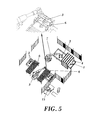
- Figure 5 illustrates a positioning implement (6) which allows positioning the cluster in the second working area (z2) during the separation process.
- Figure 6 shows an embodiment in which the first industrial manipulator (2) acts as a securing element for securing the clusters (3) during the cutting process.
- Figures 7 , 8 and 9 illustrate a third embodiment of the method of the invention (as described in claim 4) in which, as in the second embodiment, there are defined three working areas, including a third working area (z3) and a second manipulator (7) and in which the second working area (z2) for separating by means of the first manipulator (2) is arranged outside the conveyor system (1).
- a second computer vision system (12) which is arranged between the first working area (z1) and the third working area (z3) and the first computer vision system (4) is arranged between the third working area (z3) and the second working area (z2) such that the cluster moved by the second manipulator (7) from the third working area (z3) passes through the first computer vision system (4) before the separation in the second working area (z2).
- This embodiment allows preventing errors in the separation process due to possible deviations during the manipulation of the cluster from the third working area (z3) to the second working area (z2), and it is not necessary to place the cluster (3) in the second working area (z2) with a determined orientation and position.
- Figure 8 illustrates a fixing implement (5) fixing the cluster in the second working area (z2) during the process of capturing an image of the cluster by means of the first computer vision system (4), the process of calculating the separation coordinates, orientation and entering angle and the separation process.
- Figure 9 shows an embodiment in which the first industrial manipulator (2) acts as a securing element for securing the clusters (3) during the process of capturing an image of the cluster by means of the first computer vision system (4), the process of calculating the separation coordinates, orientation and entering angle and the separation process.
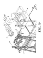
- Figure 10 illustrates a fourth embodiment of the method (according to claim 5) in which the separating system formed by at least one separating tool (8) located in the second working area (z2) is supported by a solid structure or a gantry (10) and the first industrial manipulator (2) handles a gripping tool (9).
- the cluster (3) is placed in a first working area (z1), and in a third working area (z3) the first industrial manipulator (2) grips the cluster (3) to move it to the second working area (z2) before the separation operation.
- the first computer vision system (4) is arranged between the first working area (z1) and the third working area (z3).
- the first industrial manipulator (2) positions the cluster (3) under the separating system to line up the separating system with the cutting points for cutting the cluster (3), with the suitable orientation and with the determined entering angle for each of the separations of the cluster.
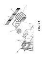
- Figure 11 illustrates a fifth embodiment of the method (according to claim 6) in which, like in the fourth embodiment, the separating system (8) located in the second working area (z2) is supported by a structure, and three working areas are distinguished.
- a second computer vision system (12) which is arranged between the first working area (z1) and the third working area (z3), has been provided, and the first computer vision system (4) is arranged between the third working area (z3) and the second working area (z2) such that the cluster (3) moved by the first manipulator (2) from the third working position (z3) passes through the first computer vision system (4) before the separation in the second working area (z2), secured by the first industrial manipulator (2).
- This embodiment allows preventing errors in the separation process due to possible deviations during the manipulation of the cluster from the third working area (z3) to the second working area (z2).
- Figure 12 schematically shows a typical conventional cluster (3) with cast parts (14) attached to respective side lines (15c) of two secondary branches (15b) attached to a connection branch (15c) of a mold (15) comprising a pouring cup (15d).
- the pouring cup (15d) is a common element in clusters (3) of one casting and could be used as a reference for gripping the clusters (3) by means of the industrial manipulator which the griping tool (9) has, regardless of the type of part (14) which is manufactured in claims 2,3,4 and 5 in which it is necessary to manipulate the cluster before the separation in a second working area (z2).
- Figure 12 shows the coordinates calculated by the first computer vision system (4) and Figure 13 shows the assignment of the entering angle based on stored data, in order to establish the points of interest.
- the system involves a new flexibility concept in the processes for separating cast parts from their cluster (3) since it adapts to any type of cluster (3) within specified dimension and weight limits.
- the first computer vision system (4) which locates in an image the pattern of the desired area and transmits the spatial coordinates-x-, -y-,-z-, - ⁇ - thereof to the first manipulator (2).
- These coordinates will be both position and orientation coordinates. They will be initially referenced to the axis of coordinates (X,Y,Z) of the first computer vision system (4), so it is necessary to make a change of base to reference them to the system of coordinates (X',Y',Z') of the industrial manipulator (2).
- the entering angle - ⁇ - at the cutting points i.e., the angle of inclination of the cutting tool, is a constant associated with each type of part and is obtained from a record stored in a database.
- Figures 14 to 18 show steps prior to an algorithm for searching for the cutting point. Any image processing program such as Microsoft Paint ® , for example can be used in these prior steps.
- the reference systems for the first computer vision system (4) and for the first industrial manipulator (2) are first defined.
- the orientation of the axes of the reference system of the first computer vision system (4) will be defined by calibrating the camera, whereby possible distortions when taking images are also corrected and the pixel-millimeter equivalence is calculated for each area of the image.
- the system of coordinates for the industrial manipulator is programmed by means of teaching.
- the selection of the system of coordinates can be any, but it is convenient for them to coincide in orientation with those of the first computer vision system (4).
- a program is loaded in the industrial manipulator which contains parameter-based movement instructions, such that through a graphic interface and the data obtained by the computer vision system information is sent to the industrial manipulator relating to positions, speeds, tool, number of points and type of movement.
- a valid camera for the application could be, for example, a 1280x960 digital camera with an 8 mm lens.
- Figure 14 depicts an image taken of a first face of a real cluster.
- Figure 15 depicts an image taken of a second face (opposite the first face) of a real cluster.
- FIG. 14 and 15 in addition to the elements forming the cluster which have already been schematically illustrated in Figures 12-13 , two small risers (16a), each attached to one of the secondary branches (15b) and to a cast part (14), and two large risers (16b), each attached to a secondary branch (15b) and to two cast parts (14), can also be seen.
- the cast part or parts (14) can also be attached to a feeder line, such as a side branch (15c) or a secondary branch (15b).
- Figure 21 depicts a cluster (3) similar to that of Figure 14 but which is incomplete, i.e., one of the cast parts is missing.
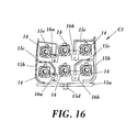
- the real image can be processed by applying different filters to improve its quality and remove background marks which could negatively affect the recognition of patterns or remove the noise present in the image. A noise-free clearer processed image-C- of the cluster (3) is thus obtained ( Figure 16 ).
- those portions of the cluster (3) which will later be used as patterns are selected and are individually stored in respective subsequent digital files as pattern images, such as for example the pattern images - D2- (which will serve to find out the cutting point in the small riser), -D3- (which will serve to find out the cutting point in the large riser), -D4- which will serve to recognize the manipulation area in which the cluster will be gripped if necessary) and -D5- (to be able to resort to the database and know which angle of inclination - ⁇ - corresponds to it or to find out the cutting point if the part has been selected as a distinctive element).
- pattern images - D2- which will serve to find out the cutting point in the small riser
- -D3- which will serve to find out the cutting point in the large riser
- -D4- which will serve to recognize the manipulation area in which the cluster will be gripped if necessary
- -D5- to be able to resort to the database and know which angle of inclination - ⁇ - corresponds
- a selection of important reference points in each of the pattern images, -D2-, -D3-, -D4-, is then performed.
- a graphic interface could then be created to show the necessary information to the user, for example by using the working environment of NI LabWindowsTM/CVI of the company NATIONAL INSTRUMENTS CORPORATION® of Texas, USA.
- an interface has been created in which the captured image, the location of the cutting points thereon, and the calculated coordinates, orientation and entering angle of each cutting point are shown. It also offers the possibility of changing the cutting points, orientation and entering angle for the cases in which the user does not agree with those calculated by the program.
- the entering angle database in which the type of part and the entering angle corresponding to it are indicated, can be for example a ".txt” file created with the Windows ® "wordpad”.
- IMAQ Vision for LabWindows ® /CVI IMAQ Vision for LabWindows ® /CVI
- MVT ec® HALCON libraries could be used.
- the "IMAQ Vision for LabWindows ® CVI” libraries have been used, in which it is possible to program directly in C.
- a series of functions are executed which allow the program to "learn” previously saved images in order to be able to subsequently recognize them within an image (the previously taken patterns).
- a series of parameters are configured to search for the pattern as the position in which it is expected to be found (360°), the minimum match which must exist to consider the search as valid, number of iterations which are to be performed etc.
- an image of the cluster is captured and it is processed.
- the same filters mentioned above in the defining patterns are used to remove noise and obtain a clearer image.
- a search for patterns is subsequently performed. If the system finds any matching pattern, information about the position in which the pattern has been found, its rotation with respect to the original pattern, the scale with respect to the original pattern, the match degree.... is obtained. This is performed with all the aforementioned pattern images -D2-, -D3-, -D4-, D5-.
- the desired points can be selected on the image, the coordinates that the mouse has on the screen of the interface and the orientation of the cutting line that it draws on the screen when clicking on it being taken. These data are given according to the size of the computer screen.
- the operator enters it manually through a keyboard.
- the pulses of an encoder placed on the conveyor system are read by means of a specific card; the pulses are then transformed into a linear distance according to the parameters of the encoder; the amount obtained is added to the previous spatial coordinates, and finally, a change of base is performed to reference the coordinates with respect to the reference system of the first industrial manipulator (2) as in the previous cases.
- a name is assigned to each type of part and the .txt file is subsequently run through to extract the entering angle corresponding to the located name.
- This information is sent to the controller of the industrial manipulator. To that end, it is necessary to set up a communication between the computer equipment and the controller. For example, a communication under the TCP protocol by means of sockets could be used. It is then necessary to define a frame common to both applications in which the information to be sent is structured.
- the industrial manipulator interprets the frame and accesses the indicated point with the rotation and the entering angle received. Furthermore, it corrects its position in a closed loop according to the degree of advance of the cluster.
- Figure 23 shows a separating system formed by several separating tools (8) for the purpose of performing several part separations simultaneously.
- These tools can also be dynamic separating tools, provided with motors and movement guides allowing them to move in different directions and having external communication whereby they receive the position to reach.
- the position and orientation thereof can thus be configured according to received data, and therefore several separations can be performed simultaneously.
- Figure 24 shows a possible embodiment of a separating system (8) formed by 4 separation tools with relative movement with respect to one another.
- direction X refers to the longitudinal direction of the cluster
- direction Y refers to the direction perpendicular to the former in the plane
- direction Z refers to the direction corresponding to the height of the cluster.
- the separating tools move by means of linear screw modules operated by a gear motor.
- the screw of the modules of the Y axis allows symmetrical movement of the two separating tools by means of a single motor.
- each separating tool (81, 82, 83, 84) is controlled by means of a PCL.
Landscapes
- Engineering & Computer Science (AREA)
- Mechanical Engineering (AREA)
- Robotics (AREA)
- Manipulator (AREA)
- Numerical Control (AREA)
Abstract
Description
- The present invention is comprised in the technical field of the iron and steel industry and, particularly, in the sector of separating parts from sets of parts manufactured by casting supported by a common structure (clusters).
- Casting clusters usually comprise pouring cups or gates, feeder lines, risers and cast parts which can be attached to a riser and/or to a feeder line. The filling cups, feeder lines and risers are conduits and cavities through which the molten material in the mold has flowed to form the cast parts. The feeder lines can comprise a connection branch communicated with the gate and side and secondary lines which feed the cast parts or the risers. The manufacture of cast parts in molds in which the cast parts are obtained in clusters requires separating the cast parts from the risers or feeder lines at determined cutting points, for which cutting tools are normally used.
- This task is normally performed manually, which involves tedious work requiring a great effort by the operator who performs the task. These operators are subjected to noise and fumes present in the installation, work in a non-ergonomic posture and may be injured due to an incorrect use of the cutting tool, so their work quality is seriously affected. Furthermore, the correct result depends on the experience and on the mood of the worker.
- Sometimes dies are used which are specifically designed to automatically separate the parts from the rest of the cluster; however the presence of abrasive sand on the parts greatly minimizes the service life of the dies, entailing very high maintenance times not suited for daily production. On the other hand, there are a large number of references, making it necessary to design and acquire a specific die for each of them, so the profitability thereof is seriously questioned.
- In view of the aforementioned problems and due to the large variety of parts of this type, it is laborious to determine for each part the access points of the tool as well as the cutting and entering angle thereof which allow a precise and accurate separation of the cast parts from the clusters and more specifically from the risers or from the feeder lines to which they are attached, which is essential for automating the separation of the cast parts from the cluster (from the riser or, where appropriate, from the feeder lines) to which they are attached.
- Although various systems for separating cast parts from their clusters which attempt to mitigate this laboriousness have been designed, such as those described in patent documents
JP2000225459(A JP2000317622(A FR2907039(A1 FR2901161 (A1 WO9738822(A1 US6364032(B1 ), currently none of these systems allows an automated operation which allows reducing that laboriousness, maintaining the flexibility of the manual process and simultaneously assuring the performance of the precise cuts at the points which are specifically required for each specific part in order to efficiently separate the cast parts from the clusters. - Patents
JP 2010 234431 A JP 4 071769A - Therefore, the method of the invention is an advance in terms of flexibility, since it automatically calculates the cutting points for each specific part individually, regardless of the position or orientation in which the cluster is located and of the type of part in question. This solves problems such as the deformation of the feeder lines during the solidification process or the existence of an excessively large number of references as occurs with the use of dies, for example. Furthermore, it is not necessary to stop the production every time the type of part is changed, it being possible to work with several references simultaneously. On the other hand, the method of the invention entails shorter commissioning times than the automatic solutions present up until now and eliminates the need for expert personnel, even the worker being able to configure the system, without needing to perform a prior teaching programming on the robotic system. Finally, the method of the invention further allows human intervention for selecting or correcting said points if necessary, through a human-machine interface. It is thus the operator himself who selects the angle of the tool and the cutting point and guides such tool towards the desired point during the industrial process without needing to reprogram the system or physically intervene in the working area of the tool.
- The object of the present invention is to overcome the drawbacks of the state of the art detailed above by means of a method and a system for separating cast parts from clusters obtained by means of casting processes, the cluster comprising a pouring cup, feeder lines, cast parts and feeding risers. In the scope of the present invention, clusters are understood as both complete clusters and incomplete clusters (a part which has become detached from the cluster, for example, is missing).
- The method of the invention comprises:
- a) defining a spatial reference system (X, Y, Z) for a first computer vision system, defining a spatial reference system (X',Y',Z') for a first industrial manipulator in a second working area, and interrelating both spatial reference systems according to the distances (x ,y ,z) separating them and the orientation of each axis;
- b) developing a basic programming algorithm for the first industrial manipulator based on movement instructions through parameters;
- c) storing data corresponding to the cast parts, feeder lines and risers of the clusters, comprising data of the cutting points for cutting the cast parts from the cluster;
- d) placing the cluster in a first working area;
- e) obtaining an image of the casting cluster by means of the first computer vision system;
- f) processing the image of the cluster obtained by the first computer vision system in phase e) to obtain the orientation of the cast parts and the coordinates of the cutting points according to the data of the image of phase e) and the data stored in c);
- g) converting the coordinates of the cutting points and orientation of the parts of the spatial reference system of the first computer vision system (X, Y, Z) to the spatial reference system of the first industrial manipulator (X', Y', Z');
- h) determining the entering angle for separating each cast part based on reference entering angle values contained in a database in computer equipment;
- i) transmitting the coordinates and orientations calculated and the entering angle of phase h) to the first industrial manipulator which allows confronting the separating system containing at least one separating tool with the cutting point for cutting the cluster, with the suitable orientation and with the determined entering angle. The first manipulator can bear the separating tool in order to apply it on the part which remains still, or the first manipulator can bear the part and take it to the separating tool which is assembled on a structure;
- j) securing the cluster in the second working area and separating each cast part from the cluster by means of the separating system in the second working area.
- In one embodiment, the method can comprise handling the separating system by the first industrial manipulator. To that end, the separating system will be defined as a work tool. Subsequently, rather than proceeding as usual, programming specific spatial points by means of "teaching", an algorithm is defined which is based on movement instructions through parameters, therefore valid for all existing references.
- It can additionally comprise fixing the cluster (for example by means of a fixing implement) on a conveyor system which moves the cluster from the first working area to the second working area, in which the first manipulator with the separating system is located. The cluster can be placed in the first area manually by an operator, for example, or can come from a previous installation. The method comprises calculating the advance distance of the cluster from phase e) to update the cutting coordinates of phase g).
- The clusters herein described can be supported on the conveyor system on both faces, i.e., face up and face down. Sometimes one of the faces contains notches or lugs in order to support the separating tool and facilitate the cutting, such that if the separation is performed on the other face of the cluster, it will probably be erroneous. In the following embodiments, the face of the cluster is identified by means of a computer vision system and the data is sent to the industrial manipulator; in the event that the face of the cluster is not the most suitable, the manipulator is responsible for turning it over.
- In a second alternative embodiment, the separating system is also handled through the first industrial manipulator, however the second working area is outside the conveyor system. In a third working area (arranged after the first computer vision system), a second manipulator has been provided which transfer the cluster from the third working area to the second working area in which the first manipulator with the separating tool is located.
- For transfer, the industrial manipulator could grab, for example, the cluster by the gate, a common part for all the casting clusters, universal and identical for all the references within the same casting, which enables handling different types of references with the same tool, reducing tool change times and costs.
- In this embodiment, the first computer vision system is arranged between the first working area and the third working area such that it captures the image of the cluster before the second manipulator transfers the cluster to the second working area for the separation.
- In this second embodiment, the method comprises the following phases:
- k) defining a spatial reference system (X", Y", Z") for a second industrial manipulator which handles a gripping tool in a third working area, and interrelating the spatial reference system (X", Y", Z") of the second manipulator with the spatial reference system (X, Y, Z) of the first computer vision system according to the distances (x1, y1, z1) separating them and the orientation of each axis;
- l) storing data corresponding to a gripping element, comprising data of the gripping point for gripping the casting cluster and the face of the cluster;
and in that it comprises the following phases after phase e) and before phase i): - m) processing the image of the cluster obtained by the first computer vision system in phase e) to obtain the orientation of the cluster, the face of the cluster and the gripping point according to data of the image of phase e) and the data stored in phase I);
- n) converting the gripping coordinates and orientation of the cluster of phase m) of the spatial reference system (X, Y, Z) of the first computer vision system to the spatial reference system (X", Y", Z") of the second industrial manipulator;
- o) transmitting the gripping coordinates, face of the cluster and the orientation of the cluster of phase m) to the second industrial manipulator to grip the cluster by the gripping element. Face of the cluster is understood as transmitting the data of the first or second face of the cluster which remains opposite the separating tool and therefore on which the separating tool will act;
- p) gripping and turning the cluster over by means of the gripping tool of the second industrial manipulator based on coordinates of phase n), in the third working area;
- q) positioning the cluster on the second working area to place the cluster in a determined position and orientation;
and in that it comprises the following phase after phase e) and before phase g): - r) updating the coordinates of the cutting points, orientation of the parts and entering angle according to the face of the cluster and references to gripping coordinates of the first computer vision system
- This positioning is necessary so that the first manipulator can separate each cast part based on the data of the image obtained by the first computer vision system. In the first embodiment of the invention described above, this positioning in a determined position and orientation of the cluster is not necessary because the clusters are fixed from the first working area to the second working area. The positioning can be done by means of a positioning implement configured to fix the cluster in a determined position and orientation, or the second industrial manipulator could secure the cluster during the cutting operation.
- In this embodiment, the conveyor system moving the cluster from the first working area to the third working area and the update of the gripping coordinates of phase n) according to the advance of the cluster on the conveyor system have also been provided.
- In a third embodiment, as in the second embodiment, the second working area is outside the conveyor system, and the separating system is handled by the first industrial manipulator and a second manipulator has been provided in the third working area transferring the cluster from the third working area to the second working area where the first manipulator with the separating system is located.
- In this third embodiment, the incorporation of a second computer vision system which is arranged between the first working area and the third working area has been provided.
- The second computer vision system captures the image of the cluster before the second manipulator transfers the cluster to the second working area for the separation. This second computer vision system is configured to obtain data of the cluster which allow obtaining the face of the cluster, the coordinates of the gripping point and orientation of the cluster.
- Possible deviations in the coordinates of the cutting points and orientation of the parts due to the handling of the cluster by the second industrial manipulator are thus prevented.
- In this embodiment, the first computer vision system is arranged before the second working area and after the third working area, the first vision system being outside the conveyor system, and is configured to obtain data of the cluster which allow obtaining the coordinates of the cutting points and orientation of the parts. In this embodiment, a positioning of the clusters as in the second embodiment is not necessary because this phase is prior to the phase for processing the image of the cluster by the first computer vision system.
- The cluster could be secured in the second working area by means of a fixing implement preventing the cluster from moving during the separation operation. In this case, the second working area can comprise a cluster delivery area for the delivery by means of the second manipulator and a separation area for the separation by the first manipulator, the first computer vision system being arranged between both. In this case, there may be an additional conveyor system which moves the cluster from the delivery area to the separation area and can comprise fixing the cluster in the delivery area.
- The cluster could also be secured through the second industrial manipulator to prevent the cluster from moving during the separation operation. In this case, the second working area will have a single area where the first computer vision system is located and the separation operation is performed.
- In the third embodiment of the invention, the method comprises the following phases:
- k1) defining a spatial reference system (X", Y", Z") for a second industrial manipulator which handles a gripping tool in a third working area, defining a spatial reference system (X"', Y"', Z"') for a second computer vision system arranged between the first working area and the third working area, and interrelating both reference systems according to the distances (x1,y1,z1) separating them and the orientation of each axis;
- l1) storing data corresponding to a gripping element, comprising data of the gripping point for gripping the casting cluster and face of the cluster;
and in that it comprises the following phases after phase d) and before phase e): - m1) obtaining an image of the casting cluster by means of the second computer vision system;
- n1) processing the image of the cluster obtained by the second computer vision system in phase m1) to obtain the face of the cluster, the orientation of the cluster and the coordinates of the gripping point according to data of the image of phase m1) and the data stored in phase l1);
- o1) converting the coordinates of the gripping point and orientation of the cluster of phase n1) of the spatial reference system (X"', Y"', Z"') of the second computer vision system to the spatial reference system (X", Y", Z") of the second industrial manipulator;
- p1) transmitting the coordinates calculated in o1), orientation of the cluster and the face of the cluster to the second industrial manipulator to grip the cluster at the gripping point;
- q1) gripping and turning the cluster over according to the face of the cluster by means of the gripping tool of the second industrial manipulator based on coordinates of phase o1), in the third working area;
- r1) positioning the cluster on the second working area in an undetermined orientation.
- Obtaining the image by means of the second computer vision system in phase m1) is performed once the cluster has been placed in phase d) and before the gripping phase q1) in the third working area and obtaining the image by means of the first computer vision system in phase e) is performed in the second working area after phase r1) and before the separation of phase j).
- It has also been provided in this embodiment for the conveyor system to move the cluster from the first working area to the third working area and to update the gripping coordinates of phase o1) according to the advance of the cluster on the conveyor system.
- In a fourth embodiment, the separating system is located on a structure in the second working area, which can be external to the conveyor system or not. The first industrial manipulator, which handles a gripping tool, transfers the cluster from the third working area to the second working area and positions the cluster under the separating system in the position, orientation and under the entering angle calculated for each of the separating points, securing the cluster during the cutting phase for correct separation of the parts.
- In this embodiment the first computer vision system is arranged between the first working area and the third working area such that it captures the image of the cluster before the first manipulator transfers the cluster to the second working area for the separation.
- In this fourth embodiment, the method comprises the following phases:
- k2) defining a second spatial reference system (X"', Y"', Z"') located at the origin of the separating system for the first industrial manipulator;
- l2) storing data corresponding to a gripping element, comprising data of the gripping point for gripping the casting cluster, and face of the cluster;
- m2) processing the image of the cluster obtained by the first computer vision system in phase e) to obtain the face of the cluster, orientation of the cluster and the gripping point according to data of the image of phase e) and the data stored in phase l2);
- n2) converting the gripping coordinates and orientation of the cluster of phase m2) of the spatial reference system (X, Y, Z) of the first computer vision system to the spatial reference system (X', Y', Z') of the first industrial manipulator;
- o2) transmitting the gripping coordinates, face of the cluster and orientation of the cluster to the first industrial manipulator to grip the cluster by the gripping element;
- p2) gripping and turning the cluster over according to the face of the cluster by means of the gripping tool handled by the first industrial manipulator based on coordinates of phase n2) in a third working area;
- q2) converting the coordinates of the cutting points, orientation of the parts and entering angle of the spatial reference system (X', Y', Z') of the first industrial manipulator to the second spatial reference system (X"', Y"', Z"') of the first industrial manipulator referenced to the separating system;
- r2) positioning the separating points for separating the cluster under the separating system in the second working area according to separation coordinates, orientation of the parts and entering angle.
- Obtaining the image by means of the first computer vision system in phase e) is performed once the cluster has been placed in phase d) and before the gripping phase p2) in the third working area.
- It has also been provided in this embodiment for the conveyor system to move the cluster from the first working area to the third working area and to update the gripping coordinates of phase n2) according to the advance of the cluster on the conveyor system.
- In a fifth embodiment, like in the fourth embodiment, the separating system is located on a structure in the second working area, which can be external to the conveyor system or not, and the first industrial manipulator, which handles a gripping tool, transfers the cluster from the third working area to the second working area and positions the cluster under the separating system in the position, orientation and under the entering angle calculated for each of the separating points, securing the cluster during the cutting phase for correct separation of the parts.
- In this fifth embodiment, the incorporation of a second computer vision system which is arranged between the first working area and the third working area has been provided.
- The second computer vision system captures the image of the cluster before the second manipulator transfers the cluster to the second working area for the separation. This second computer vision system is configured to obtain data of the cluster which allow obtaining the face of the cluster, the coordinates of the gripping point and orientation of the cluster.
- In this embodiment the first computer vision system is arranged before the second working area and after the third working area and is configured to obtain data of the cluster which allow obtaining the coordinates of the cutting points and orientation of the parts.
- Possible deviations in the coordinates of the cutting points and orientation of the parts due to the handling of the cluster by the first industrial manipulator are thus prevented.
- In the fifth embodiment of the invention the method comprises the following phases:
- k3) defining a spatial reference system (X", Y", Z") for a second computer vision system which is arranged between the first working area and the third working area and interrelating the spatial reference system (X", Y", Z") of the second computer vision system with the spatial reference system (X', Y', Z') of the first industrial manipulator according to the distances (x1,y1,z1) separating them and the orientation of each axis, and defining a second spatial reference system (X"', Y"', Z"') located at the origin of the separating system for the first industrial manipulator;
- l3) storing data corresponding to a gripping element, comprising data of the gripping point for gripping the casting cluster and face of the cluster;
- m3) obtaining an image of the casting cluster by means of the second computer vision system;
- n3) processing the image of the cluster obtained by the second computer vision system in phase m3) to obtain the face and orientation of the cluster and the coordinates of the gripping point according to data of the image of phase m3) and data stored in phase l3);
- o3) converting the coordinates of the gripping point and orientation of the cluster of the spatial reference system (X", Y", Z") of the second computer vision system to the spatial reference system (X', Y', Z') of the first industrial manipulator;
- p3) transmitting the gripping coordinates, face of the cluster and orientation of the cluster to the first industrial manipulator to grip the cluster by the gripping element;
- q3) gripping and turning the cluster over according to the face of the cluster by means of the gripping tool handled by the first industrial manipulator based on coordinates of phase o3) in a third working area;
- r3) converting the coordinates of the cutting points, orientation of the parts and entering angle of the spatial reference system (X', Y', Z') of the first industrial manipulator to the spatial reference system (X"', Y"', Z"') of the first industrial manipulator referenced to the separating system;
- s3) positioning the separating points for separating the cluster under the separating system in the second working area according to separation coordinates, orientation of the parts and entering angle of phase r3);
- Obtaining the image by means of the second computer vision system in phase m3) is performed once the cluster has been placed in phase d) and before the gripping phase q3) in the third working area and obtaining the image by means of the first computer vision system in phase e) is performed in the second working area after phase q3) and before the separation of phase j).
- It has also been provided in this embodiment for the conveyor system to move the cluster from the first working area to the third working area and to update the gripping coordinates of phase o3) according to the advance of the cluster on the conveyor system.
- The method of the invention can comprise, before the data transmitting phase i), the modification by an operator of the coordinates of each cutting point, of the orientation of each part and of the entering angle:
- The manual selection of the cutting point and orientation.
- The entry by means of a keyboard of the desired entering angle.
- The method can comprise, before the data transmitting phase o), p1), o2) or p3), the modification by an operator of the orientation coordinates of the cluster and gripping point.
- In other words, it may be possible for an operator, through a monitor, to see the data obtained by the system and decide if, in his opinion, they must be used for the separation or if they must be modified (by clicking on the images for example).
- The separating system can be configured to allow separating several parts in a single operation by means of several static separating tools. In this embodiment, each separating system is specific for a specific reference. In this embodiment, the method cycle time is greatly reduced, which cycle time is an extremely important parameter for a technologically sound solution to be successful.
- The separating system can be configured to allow separating several parts in a single operation by means of several dynamic separating tools. By means of this embodiment, each of the separating tools will be provided with additional elements allowing its movement in different degrees of freedom, such as for example linear screw modules operated by a gear motor, being able to configure the position and orientation thereof according to data received, for example through a PLC, and therefore being able to perform several separations simultaneously. This embodiment allows adapting the separating system to any type of references present in production. In this embodiment, the method cycle time is greatly reduced, which cycle time is an extremely important parameter for a technologically sound solution to be successful.
- The method can comprise using one or several separating systems for performing phase j).
- The method can comprise, in phase c), storing data corresponding to individual pattern images of distinctive elements of each type of casting cluster, the distinctive element being a cast part or a riser of the cluster. A distinctive element is understood as a part or riser which allows identifying a type of cluster. A type of cluster is understood as all those clusters which are formed by the same type of part (same reference) regardless of the number or arrangement of the parts in the cluster, different types of cluster being considered as those which are formed by different parts. It is also understood that each cluster is formed by parts of a single reference. Depending on the type of cluster the distinctive element can be a cast part or a feeding riser.
- The distinctive elements can comprise data of distance between each pattern image and at least one cutting point for cutting a cast part from the cluster. Furthermore, in phase f) it can comprise comparing the image of the cluster obtained by the first computer vision system in phase e) with the individual pattern images of the distinctive elements stored in phase c) and obtaining the position and orientation of the mentioned distinctive element of the cluster with respect to the mentioned image of the cluster and determining the cutting point for cutting each cast part based on position coordinates provided by the first computer vision system and based on cutting coordinates of the pattern image of the distinctive element of the cluster.
- The method can comprise, in phases l) and l2), storing data corresponding to individual pattern images of distinctive elements of each type of casting cluster, the distinctive element being a gripping element, as well as differentiating distinctive elements of the face of the cluster.
- The distinctive elements can comprise data of distance between each pattern image and at least one gripping point of a gripping element for gripping the cluster. Furthermore, in phases m) and m2) it can comprise comparing the image of the cluster obtained by the first computer vision system in phase e) with the individual pattern images of the distinctive elements stored in phases l) and l2) and obtaining the position and orientation of the mentioned distinctive element of the cluster with respect to the mentioned image of the cluster and determining the gripping point of the gripping element based on position coordinates provided by the first computer vision system and based on coordinates of the gripping point of the pattern image of the distinctive element of the cluster, as well as obtaining the face of the cluster.
- The method can comprise, in phases l1) and l3), storing data corresponding to individual pattern images of distinctive elements of each type of casting cluster, the distinctive element being a gripping element, and differentiating elements of the face of the cluster.
- The distinctive elements can comprise data of distance between each pattern image and at least one gripping point of a gripping element for gripping the cluster. Furthermore, in phases n1) and n3) it can comprise comparing the image of the cluster obtained by the second computer vision system in phases m1) and m3) with the individual pattern images of the distinctive elements stored in phases l1) and l3) and obtaining the position and orientation of the mentioned distinctive element of the cluster with respect to the mentioned image of the cluster and determining the gripping point of the gripping element based on position coordinates provided by the second computer vision system and based on coordinates of the gripping point of the pattern image of the distinctive element of the cluster, as well as the face of the cluster.
- The method can comprise using a morphological analysis in which in phase c) it comprises storing data of distance between any one point of the contour of the cluster and the cutting points for cutting a cast part from the cluster. Likewise, in phase f) it comprise processing the image to remove unwanted portions of the image and obtaining information about the contour and morphology of the part. It also comprises obtaining the position and orientation of each cast part in pixels according to the information obtained in phase f) and data stored in phase c).
- Aspects and embodiments of the invention are described below on the basis of several drawings, in which
-
Figure 1 schematically illustrates a first embodiment of the method of the invention. -
Figure 2 illustrates a possible installation for carrying out the method of the invention of the embodiment ofFigure 1 . -
Figure 3 illustrates an alternative installation for carrying out the method of the invention of the embodiment ofFigure 1 . -
Figure 4 schematically illustrates a second embodiment of the method of the invention. -
Figure 5 illustrates a possible installation for carrying out the method of the invention of the embodiment ofFigure 4 . -
Figure 6 illustrates a possible installation for carrying out the method of the invention of the embodiment ofFigure 4 , in which the first industrial manipulator acts as a securing element for securing the clusters during the cutting process. -
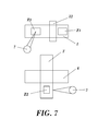
Figure 7 schematically illustrates a third embodiment of the method of the invention. -
Figure 8 illustrates a possible installation for carrying out the method of the invention of the embodiment ofFigure 7 . -
Figure 9 illustrates a possible installation for carrying out the method of the invention of the embodiment ofFigure 7 in which the first manipulator acts as a securing element for securing the clusters during the image capture process by means of the first computer vision system. -
Figure 10 illustrates a fourth embodiment of the method of the invention in which the separating system is supported by a structure. -
Figure 11 illustrates a fifth embodiment of the method of the invention in which the separating system is supported by a structure and a second computer vision system has been provided between the first and third working areas. -
Figure 12 illustrates an embodiment of a cluster to which the present invention, the global reference system, the recognition of the gripping area and of a part contained in the cluster as well as the coordinates calculated by the computer vision system in the cluster can be applied. -
Figure 13 shows the assignment of the entering angle of the cutting element based on stored data. -
Figure 14 schematically shows an embodiment of an image taken of a first face of a real cluster. -
Figure 15 schematically shows an embodiment of an image taken of a second face of a real cluster. -
Figure 16 schematically shows an embodiment of a preprocessed image based on the real image ofFigure 14 , to remove noise and improve the image. -
Figure 17B schematically shows an embodiment of a pattern image corresponding to one of the small risers shown inFigure 16 . -
Figure 17C schematically shows an embodiment of a pattern image corresponding to one of the large risers shown inFigure 16 . -
Figure 17D schematically shows an embodiment of a pattern image corresponding to the pouring cup shown inFigure 16 . -
Figure 17E schematically shows an embodiment of a corresponding pattern image of one of the cast parts shown inFigure 16 . -
Figure 18B schematically shows an image of the cutting point assigned to the pattern image shown inFigure 17B . -
Figure 18C schematically shows an image of the cutting point assigned to the pattern image shown inFigure 17C . -
Figure 18D schematically shows an image of the gripping point assigned to the pattern image shown inFigure 17D . -
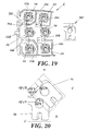
Figure 19 schematically shows the identification of a small riser present in the processed image of a real cluster based on the pattern image of the real riser. -
Figure 20 schematically shows the calculation of the cutting point based on the information returned by the computer vision system. -
Figure 21 shows an incomplete cluster. -
Figure 22 shows the phase for fixing the parts by means of a fixing implement which is horizontal, vertical or at a determined angle. -
Figure 23 shows a separating system formed by several separating tools. -
Figure 24 shows a separating system formed by several separating tools, in which the separating tools have the possibility of relative movement with respect to one another and of rotation about themselves. - In these figures there are reference numbers identifying the following elements
- 1
- first conveyor system
- 1'
- second conveyor system
- 2
- first industrial manipulator
- 3
- clusters
- 4
- first computer vision system
- 5
- fixing implement
- 6
- positioning implement
- 7
- second manipulator
- 8
- separating tool
- 9
- gripping tool
- 10
- structure/gantry
- 12
- second computer vision system
- 13
- computer equipment
- 14
- cast parts
- 15a
- connection branch
- 15b
- secondary branches
- 15c
- side branches
- 15d
- pouring cup
- 16a
- small riser
- 16b
- large riser
- B
- real image of the cluster
- C
- processed image of the cluster
- C1
- preprocessed image of the cluster
- D2
- pattern image of the small riser
- D3
- pattern image of the large riser
- D4
- pattern image of the pouring cup
- D5
- pattern image of the cast part
- 81-84
- schematic depiction of separating tools
-
Figures 1 to 11 illustrate possible separation installations for separating parts in which the present invention can be integrated. As can be seen, the clusters (3) of cast parts to be separated reach the separation installation from a previous manufacturing process or by means of an operator. - The cluster (3) will pass through a first computer vision system (4) which captures an image of the cluster. Since it is a static vision system, it can be protected against high temperatures, fumes and sand present in the installation by means of a protective casing, as well as maintain continuous control over the illumination and prevent interferences with the outside. The information obtained by the first computer vision system will be transmitted to computer equipment (13) which will manage the data of the first computer vision system (4). The position of important points with respect to a predetermined reference of a cast part (14) or a riser (16a, 16b) for each type of cluster (3), as well as the entering angle for the separating tool (8) according to the type of part (14), by means of the entry of, for example, pattern images or an electronic model and a database, will be transmitted to the mentioned computer equipment (13) in its start-up. The computer equipment (13) will use the information of the pattern image of the cast part or riser as well as the processed images from the first computer vision system (4) to calculate the optimal access points of the separating tool (8), orientation of the part and entering angle. The computer equipment (13) includes the functionality of displaying, reviewing and modifying, if the operator located in a control station considers it convenient or necessary, the coordinates of the access point of the separating tool (8), the orientation of the part and the entering angle of the tool, using a graphic interface for that purpose.
- The calculated coordinates of the separating points and the orientation of the parts, the reference system (X, Y, Z) of the first computer vision system (4) will subsequently be converted to the reference system (X', Y', Z') of a first industrial manipulator (2).
- The data will then be transmitted to a first industrial manipulator (2). To that end, an Ethernet or RS-232 communication, for example, could be set up between the computer equipment (13) and the controller of the first industrial manipulator (2).
- The cluster (3) can additionally move by means of a conveyor system (1), so the advance of the cluster (3) will be calculated by means of reading pulses of an encoder and the transformation thereof into linear distance. This reading of pulses could be done either from the computer equipment (13) with an I/O card or from the controller of the industrial manipulator with an encoder interface such as DSQC 377 A/B of ABB®.
- The first industrial manipulator (2) will perform the necessary movements which allow confronting the separating system containing at least one separating tool (8) with at least one cutting point for cutting the cluster (3), with the suitable orientation and with the determined entering angle in order to perform the separation.
-
Figures 1, 2 and3 illustrate a first embodiment of the method (according toclaims 1 and 2) of the invention in which there is observed a first working area (z1) in which an operator fixes the clusters by means of a fixing implement (5) in any position on a conveyor system (1), for the purpose of maintaining the cutting coordinates after each separation. The fixing implement (5) will be a universal implement serving to fix different references of cast parts (14). An example of this implement could be a set of magnetized sheets on the conveyor system in which the operator chooses when he wishes to magnetize/demagnetize. Another possible option could be a set of clamps fixing the part by any of the feeder lines. The fixing implement (5) can fix the cluster horizontally on the conveyor system (1) or vertically, as depicted inFigure 16 , or at a determined angle. - There are also observed a first computer vision system (4) for obtaining an image of the mentioned cluster (3) and the processing thereof according to phases f) to h) of the method of the invention, and a second working area (z2) in which a first industrial manipulator (2), which handles a separating system containing at least one separating tool for separating the cast parts (14) according to the coordinates of the cutting points, orientation of the parts and entering angle transferred in phase i), can work.
- In this embodiment the first computer vision system (4) is arranged after the first working area (z1) and before the second working area (z2). Fixing the cluster (3) by means of the fixing implement (5) is performed manually by an operator. A second operator removing the fixing implement (5) from the cast part (14) once the cluster has been separated and placing it on a carousel conveyor which returns the fixing implement to the first working area (z1) has also been depicted.
-
Figures 2 and3 respectively depict two possible alternative solutions for the fixing implement (5) and conveyor system (1). -
Figures 4 ,5 and6 illustrate a second embodiment of the method of the invention (as described in claim 3) in which there are observed a first working area (z1) where the cluster (3) is placed, a first computer vision system (4) for obtaining an image of the mentioned cluster (3) and processing it according to phases f) to h) of the method of the invention and a second working area (z2) in which a first industrial manipulator (2) can work, which industrial manipulator handles a separating system containing at least one separating tool (8) for separating the cast parts (14) according to the coordinates of the cutting points, orientation of the parts and entering angle transferred in phase i). In this embodiment, the cluster (3) is arranged in the first working area (z1) on a conveyor system (1) but it is not necessary to fix the cluster by means of the fixing implement. In this case, the conveyor system (1) moves the cluster through the first computer vision system (4) to a third working area (z3). - In this embodiment, there has also been provided a second industrial manipulator (7) which is configured to move the cluster (3) from the third working area (z3) to the second working area (z2) to separate the cast parts (14). The second manipulator (7) positions the cluster in the second working area (z2) with a determined orientation and position. In this case, the second working area (z2) is arranged outside the conveyor (1). The first computer vision system (4) is arranged between the first working area (z1) and the third working area (z3).
-
Figure 5 illustrates a positioning implement (6) which allows positioning the cluster in the second working area (z2) during the separation process. -
Figure 6 shows an embodiment in which the first industrial manipulator (2) acts as a securing element for securing the clusters (3) during the cutting process. -
Figures 7 ,8 and9 illustrate a third embodiment of the method of the invention (as described in claim 4) in which, as in the second embodiment, there are defined three working areas, including a third working area (z3) and a second manipulator (7) and in which the second working area (z2) for separating by means of the first manipulator (2) is arranged outside the conveyor system (1). - In this case, there has been provided a second computer vision system (12) which is arranged between the first working area (z1) and the third working area (z3) and the first computer vision system (4) is arranged between the third working area (z3) and the second working area (z2) such that the cluster moved by the second manipulator (7) from the third working area (z3) passes through the first computer vision system (4) before the separation in the second working area (z2). This embodiment allows preventing errors in the separation process due to possible deviations during the manipulation of the cluster from the third working area (z3) to the second working area (z2), and it is not necessary to place the cluster (3) in the second working area (z2) with a determined orientation and position.
- In
Figure 8 illustrates a fixing implement (5) fixing the cluster in the second working area (z2) during the process of capturing an image of the cluster by means of the first computer vision system (4), the process of calculating the separation coordinates, orientation and entering angle and the separation process. -
Figure 9 shows an embodiment in which the first industrial manipulator (2) acts as a securing element for securing the clusters (3) during the process of capturing an image of the cluster by means of the first computer vision system (4), the process of calculating the separation coordinates, orientation and entering angle and the separation process. -
Figure 10 illustrates a fourth embodiment of the method (according to claim 5) in which the separating system formed by at least one separating tool (8) located in the second working area (z2) is supported by a solid structure or a gantry (10) and the first industrial manipulator (2) handles a gripping tool (9). - Like in the second embodiment, three working areas are defined. The cluster (3) is placed in a first working area (z1), and in a third working area (z3) the first industrial manipulator (2) grips the cluster (3) to move it to the second working area (z2) before the separation operation.
- The first computer vision system (4) is arranged between the first working area (z1) and the third working area (z3).
- The first industrial manipulator (2) positions the cluster (3) under the separating system to line up the separating system with the cutting points for cutting the cluster (3), with the suitable orientation and with the determined entering angle for each of the separations of the cluster.
-
Figure 11 illustrates a fifth embodiment of the method (according to claim 6) in which, like in the fourth embodiment, the separating system (8) located in the second working area (z2) is supported by a structure, and three working areas are distinguished. - In this case, a second computer vision system (12) which is arranged between the first working area (z1) and the third working area (z3), has been provided, and the first computer vision system (4) is arranged between the third working area (z3) and the second working area (z2) such that the cluster (3) moved by the first manipulator (2) from the third working position (z3) passes through the first computer vision system (4) before the separation in the second working area (z2), secured by the first industrial manipulator (2).
- This embodiment allows preventing errors in the separation process due to possible deviations during the manipulation of the cluster from the third working area (z3) to the second working area (z2).
-
Figure 12 schematically shows a typical conventional cluster (3) with cast parts (14) attached to respective side lines (15c) of two secondary branches (15b) attached to a connection branch (15c) of a mold (15) comprising a pouring cup (15d). The pouring cup (15d) is a common element in clusters (3) of one casting and could be used as a reference for gripping the clusters (3) by means of the industrial manipulator which the griping tool (9) has, regardless of the type of part (14) which is manufactured inclaims -
Figure 12 shows the coordinates calculated by the first computer vision system (4) andFigure 13 shows the assignment of the entering angle based on stored data, in order to establish the points of interest. The system involves a new flexibility concept in the processes for separating cast parts from their cluster (3) since it adapts to any type of cluster (3) within specified dimension and weight limits. - To establish the cutting points, their location for positioning the cutting tool is identified by means of the first computer vision system (4), which locates in an image the pattern of the desired area and transmits the spatial coordinates-x-, -y-,-z-, -β- thereof to the first manipulator (2). These coordinates will be both position and orientation coordinates. They will be initially referenced to the axis of coordinates (X,Y,Z) of the first computer vision system (4), so it is necessary to make a change of base to reference them to the system of coordinates (X',Y',Z') of the industrial manipulator (2).
- According to
claims - The entering angle -α- at the cutting points, i.e., the angle of inclination of the cutting tool, is a constant associated with each type of part and is obtained from a record stored in a database.
-
Figures 14 to 18 show steps prior to an algorithm for searching for the cutting point. Any image processing program such as Microsoft Paint®, for example can be used in these prior steps. - The reference systems for the first computer vision system (4) and for the first industrial manipulator (2) are first defined.
- The orientation of the axes of the reference system of the first computer vision system (4) will be defined by calibrating the camera, whereby possible distortions when taking images are also corrected and the pixel-millimeter equivalence is calculated for each area of the image.
- The system of coordinates for the industrial manipulator is programmed by means of teaching. The selection of the system of coordinates can be any, but it is convenient for them to coincide in orientation with those of the first computer vision system (4).
- It is necessary to accurately know the distance x,y,z separating both systems of coordinates and the difference in the orientation of their angles in order to be able to subsequently perform a change of base.
- It is not necessary to program any movement instruction for the industrial manipulator by means of teaching or to define specific spatial points according to the different types of clusters as occurs in other automatic systems which need prior input about the movements of the industrial manipulator.
- By means of the described invention, a program is loaded in the industrial manipulator which contains parameter-based movement instructions, such that through a graphic interface and the data obtained by the computer vision system information is sent to the industrial manipulator relating to positions, speeds, tool, number of points and type of movement. By means of a standard program, it is thus possible to autonomously command the industrial manipulator so that it adapts to the activity to perform and to the type of part with which it must work.
- The camera and lens to be used will depend on different factors such as the working area, the accuracy required, the working distance, the type of connection desired... A valid camera for the application could be, for example, a 1280x960 digital camera with an 8 mm lens.
-
Figure 14 depicts an image taken of a first face of a real cluster.Figure 15 depicts an image taken of a second face (opposite the first face) of a real cluster. - In the case of
Figures 14 and 15 , in addition to the elements forming the cluster which have already been schematically illustrated inFigures 12-13 , two small risers (16a), each attached to one of the secondary branches (15b) and to a cast part (14), and two large risers (16b), each attached to a secondary branch (15b) and to two cast parts (14), can also be seen. The cast part or parts (14) can also be attached to a feeder line, such as a side branch (15c) or a secondary branch (15b).Figure 21 depicts a cluster (3) similar to that ofFigure 14 but which is incomplete, i.e., one of the cast parts is missing. The real image can be processed by applying different filters to improve its quality and remove background marks which could negatively affect the recognition of patterns or remove the noise present in the image. A noise-free clearer processed image-C- of the cluster (3) is thus obtained (Figure 16 ). - On the processed image-C, those portions of the cluster (3) which will later be used as patterns, such as for example and according to what is shown in
Figures 17B-17E , of the small riser (16a), of the large riser (16b), of the pouring cup (15d) and of the cast part (14), are selected and are individually stored in respective subsequent digital files as pattern images, such as for example the pattern images - D2- (which will serve to find out the cutting point in the small riser), -D3- (which will serve to find out the cutting point in the large riser), -D4- which will serve to recognize the manipulation area in which the cluster will be gripped if necessary) and -D5- (to be able to resort to the database and know which angle of inclination - α- corresponds to it or to find out the cutting point if the part has been selected as a distinctive element). - A selection of important reference points in each of the pattern images, -D2-, -D3-, -D4-, is then performed.
- A graphic interface could then be created to show the necessary information to the user, for example by using the working environment of NI LabWindows™/CVI of the company NATIONAL INSTRUMENTS CORPORATION® of Texas, USA. Thus, in the embodiment described herein, an interface has been created in which the captured image, the location of the cutting points thereon, and the calculated coordinates, orientation and entering angle of each cutting point are shown. It also offers the possibility of changing the cutting points, orientation and entering angle for the cases in which the user does not agree with those calculated by the program.
- The entering angle database, in which the type of part and the entering angle corresponding to it are indicated, can be for example a ".txt" file created with the Windows® "wordpad".
- In relation to the processing of the image, different vision libraries such as, for example, "IMAQ Vision for LabWindows®/CVI", or other more powerful ones such MVTec® HALCON libraries could be used.
- In this case, the "IMAQ Vision for LabWindows® CVI" libraries have been used, in which it is possible to program directly in C. Initially, when the program is started, a series of functions are executed which allow the program to "learn" previously saved images in order to be able to subsequently recognize them within an image (the previously taken patterns). Furthermore, a series of parameters are configured to search for the pattern as the position in which it is expected to be found (360°), the minimum match which must exist to consider the search as valid, number of iterations which are to be performed etc.
- When a part is detected, by means of a photoelectric sensor for example, an image of the cluster is captured and it is processed. To that end, the same filters mentioned above in the defining patterns are used to remove noise and obtain a clearer image. A search for patterns is subsequently performed. If the system finds any matching pattern, information about the position in which the pattern has been found, its rotation with respect to the original pattern, the scale with respect to the original pattern, the match degree.... is obtained. This is performed with all the aforementioned pattern images -D2-, -D3-, -D4-, D5-.
- Then a series of trigonometric functions are applied to obtain the coordinates of the desired points with respect to the coordinate system origin of the computer vision system initially defined in millimeters.
- To offer the possibility of changing the cutting points and orientation of each part, the desired points can be selected on the image, the coordinates that the mouse has on the screen of the interface and the orientation of the cutting line that it draws on the screen when clicking on it being taken. These data are given according to the size of the computer screen. To change the entering angle, the operator enters it manually through a keyboard.
- The coordinates referring to the coordinate origin of the computer vision system and transformed to millimeters are then calculated.
- It is then necessary to reference the spatial coordinates obtained to the reference system of the industrial manipulator, taking into account the advance of the part. To that end, the pulses of an encoder placed on the conveyor system are read by means of a specific card; the pulses are then transformed into a linear distance according to the parameters of the encoder; the amount obtained is added to the previous spatial coordinates, and finally, a change of base is performed to reference the coordinates with respect to the reference system of the first industrial manipulator (2) as in the previous cases.
- To calculate the entering angle, a name is assigned to each type of part and the .txt file is subsequently run through to extract the entering angle corresponding to the located name.
- This information is sent to the controller of the industrial manipulator. To that end, it is necessary to set up a communication between the computer equipment and the controller. For example, a communication under the TCP protocol by means of sockets could be used. It is then necessary to define a frame common to both applications in which the information to be sent is structured.
- Finally, the industrial manipulator interprets the frame and accesses the indicated point with the rotation and the entering angle received. Furthermore, it corrects its position in a closed loop according to the degree of advance of the cluster.
-
Figure 23 shows a separating system formed by several separating tools (8) for the purpose of performing several part separations simultaneously. - These tools can be static, for example, such that each separating system is specific for a specific reference.
- These tools can also be dynamic separating tools, provided with motors and movement guides allowing them to move in different directions and having external communication whereby they receive the position to reach. The position and orientation thereof can thus be configured according to received data, and therefore several separations can be performed simultaneously.
-
Figure 24 shows a possible embodiment of a separating system (8) formed by 4 separation tools with relative movement with respect to one another. - Throughout this description, direction X refers to the longitudinal direction of the cluster, direction Y refers to the direction perpendicular to the former in the plane, and direction Z refers to the direction corresponding to the height of the cluster.
- On the X axis, the separating tools (81) and (82) are fixed and the separating tools (83) and (84) are rigidly attached, so X3=X4.
- On the other hand, in the Y direction the separating tools (81) and (82) move symmetrically, such that Y1=-Y2. The same occurs with the separating tools (83) and (84) (Y3=-Y4). Nevertheless, Y1 can be different from Y3 if the cluster requires this.
- The separating tools move by means of linear screw modules operated by a gear motor. The screw of the modules of the Y axis allows symmetrical movement of the two separating tools by means of a single motor.
- On the other hand, for the movement on X two linear screw modules working as master-slave have been used, assuring at all times that the position of both is the same.
- The positioning of each separating tool (81, 82, 83, 84) is controlled by means of a PCL.
Claims (9)
- Method for separating cast parts (14) from clusters obtained by means of casting processes, the cluster (3) comprising a pouring cup (15d), cast parts (14) attached to the cluster (3) through attachment elements (15b, 15c) and feeding risers (16a, 16b), characterized in that it comprises:a) defining a spatial reference system (X, Y, Z) for a first computer vision system (4), defining a spatial reference system (X',Y',Z') for a first industrial manipulator (2) in a second working area (z2) where the cast parts (14) are separated by means of a separating system, and interrelating both spatial reference systems according to the distances (x ,and ,z) separating them and the orientation of each axis;b) developing a basic programming algorithm for the first industrial manipulator (2) based on movement instructions through parameters;c) storing data corresponding to the cast parts (14), feeder lines (15a, 15b, 15c) and risers (16a, 16b) of the clusters, comprising data of the cutting points for cutting the cast parts (14) from the cluster (3);d) placing the cluster (3) in a first working area (z1);e) obtaining an image of the casting cluster (3) by means of the first computer vision system (4);f) processing the image of the cluster obtained by the first computer vision system (4) in phase e) to obtain the orientation of the cast parts and the coordinates of the cutting points according to the data of the image of phase e) and the data stored in c);g) converting the coordinates of the cutting points and orientation of the parts of the spatial reference system (X, Y, Z) of the first computer vision system (4) to the spatial reference system (X', Y', Z') of the first industrial manipulator (2);h) determining the entering angle for separating each cast part (14) based on reference entering angle values contained in a database in computer equipment (13);i) transmitting the coordinates and orientations calculated and the entering angle of phase h) to the first industrial manipulator (2) which allows confronting the separating system containing at least one separating tool (8) with the cutting points for cutting the cluster (3), with the suitable orientation and with the determined entering angle;j) securing the cluster in the second working area (z2) and separating each cast part (14) from the cluster (3) by means of the separating system (8) in the second working area (z2).
- Method for separating cast parts (14) according to claim 1, wherein the separating system located in the second working area (z2) is handled by the first industrial manipulator (2);
and in that phase d) comprises fixing the cluster (3) by means of a fixing implement (5) and moving the cluster from the first working area (z1) to the second working area (z2) by means of a conveyor system (1) and obtaining the image by means of the first vision system (4) in phase e) is performed once the cluster (3) has been placed in phase d);
and in that it comprises calculating the advance distance of the cluster (3) from phase e) to update the cutting coordinates of phase g). - Method for separating cast parts (14) from clusters according to claim 1, wherein the separating system located in the second working area (z2) is handled by the first industrial manipulator (2), the second working area (z2) being outside the conveyor system (1);
and in that it comprises the following phases:k) defining a spatial reference system (X", Y", Z") for a second industrial manipulator (7) which handles a gripping tool (9) in a third working area (z3) and interrelating the spatial reference system (X", Y", Z") of the second manipulator (7) with the spatial reference system (X, Y, Z) of the first computer vision system (4) according to the distances (x1, y1, z1) separating them and the orientation of each axis;l) storing data corresponding to a gripping element (15d), comprising data of the gripping point for gripping the casting cluster (3) and the face of the cluster;and in that it comprises the following phases after phase e) and before phase i):m) processing the image of the cluster obtained by the first computer vision system (4) in phase e) to obtain the orientation of the cluster, the face of the cluster and the gripping point according to data of the image of phase e) and the data stored in phase l);n) converting the gripping coordinates and orientation of the cluster of phase m) of the spatial reference system (X, Y, Z) of the first computer vision system (4) to the spatial reference system (X", Y", Z") of the second industrial manipulator (7);o) transmitting the gripping coordinates, face of the cluster and the orientation of the cluster of phase m) to the second industrial manipulator (7) to grip the cluster by the gripping element (15d);p) gripping and turning the cluster over according to the face of the cluster (3) by means of the gripping tool (9) of the second industrial manipulator (7) based on coordinates of phase n), in the third working area (z3);q) positioning the cluster (3) on the second working area (z2) to place the cluster in a determined position and orientation;and in that it comprises the following phases after phase e) and before phase g):r) updating the coordinates of the cutting points, orientation of the parts and entering angle according to the face of the cluster and referenced to gripping coordinates of the first computer vision system (4);and in that it comprises moving the cluster (3) from the first working area (z1) to the third working area (z3) by means of a conveyor system and obtaining the image by means of the first computer vision system (4) in phase e) is performed once the cluster has been placed in phase d) and before the gripping phase p) in the third working area (z3), and in that it comprises updating the gripping coordinates of phase n) according to the advance of the cluster (3) on the conveyor system (1). - Method for separating cast parts (14) from clusters according to claim 1, wherein the separating system located in the second working area (z2) is handled by the first industrial manipulator (2), the second working area (z2) being outside the conveyor system (1);
and in that it comprises the following phases:k1) defining a spatial reference system (X", Y", Z") for a second industrial manipulator (7) which handles a gripping tool (9) in a third working area (z3), defining a spatial reference system (X"', Y"', Z"') for a second computer vision system (12) which is arranged between the first working area (z1) and the third working area (z3), and interrelating both reference systems according to the distances (x1,y1,z1) separating them and the orientation of each axis;l1) storing data corresponding to a gripping element (15d), comprising data of the gripping point for gripping the casting cluster (3) and face of the cluster;and in that it comprises the following phases after phase d) and before phase e):m1) obtaining an image of the casting cluster (3) by means of the second computer vision system (12);n1) processing the image of the cluster obtained by the second computer vision system (12) in phase m1) to obtain the face of the cluster, the orientation of the cluster and the coordinates of the gripping point according to data of the image of phase m1) and the data stored in phase l1);o1) converting the coordinates of the gripping point and orientation of the cluster of phase n1) of the spatial reference system (X"', Y"', Z"') of the second computer vision system (12) to the spatial reference system (X", Y", Z") of the second industrial manipulator (7);p1) transmitting the coordinates calculated in o1), orientation of the cluster and the face of the cluster to the second industrial manipulator (7) to grip the cluster (3) at the gripping point;q1) gripping and turning the cluster over according to the face of the cluster (3) by means of the gripping tool (9) of the second industrial manipulator (7) based on coordinates of phase o1), in the third working area (z3);r1) positioning the cluster (3) on the second working area (z2) in an undetermined orientation;and in that it comprises moving the cluster (3) from the first working area (z1) to the third working area (z3) by means of a conveyor system (1), in that obtaining the image by means of the second computer vision system (12) in phase m1) is performed once the cluster has been placed in phase d) and before the gripping phase q1) in the third working area (z3), in that obtaining the image by means of the first computer vision system (4) in phase e) is performed in the second working area (z2) after phase r1) and before the separation of phase j) and in that it comprises updating the gripping coordinates of phase o1) according to the advance of the cluster (3) on the conveyor system (1). - Method for separating cast parts (14) according to claim 1, wherein the separating system located in the second working area (z2) is supported by a structure (10) and the first industrial manipulator (2) handles a gripping tool (9);
and in that it further comprises the following phases:k2) defining a second spatial reference system (X"', Y"', Z"') located at the origin of the separating system for the first industrial manipulator (2);l2) storing data corresponding to a gripping element (15d), comprising data of the gripping point for gripping the casting cluster (3), and face of the cluster;and in that it comprises the following phases after phase e) and before phase g):m2) processing the image of the cluster obtained by the first computer vision system (4) in phase e) to obtain the face of the cluster, orientation of the cluster and the gripping point according to data of the image of phase e) and the data stored in phase 12);n2) converting the gripping coordinates and orientation of the cluster of phase m2) of the spatial reference system (X, Y, Z) of the first computer vision system (4) to the spatial reference system (X', Y', Z') of the first industrial manipulator (2);o2) transmitting the gripping coordinates, face of the cluster and orientation of the cluster to the first industrial manipulator to grip the cluster by the gripping element (15d);p2) gripping and turning the cluster (3) over according to the face of the cluster by means of the gripping tool (9) handled by the first industrial manipulator (2) based on coordinates of phase n2) in a third working area (z3);and in that it comprises the following phase after phase g) and before phase i):q2) converting the coordinates of the cutting points, orientation of the parts and entering angle of the spatial reference system (X', Y', Z') of the first industrial manipulator (2) to the second spatial reference system (X"', Y"', Z"') of the first industrial manipulator (2) referenced to the separating system;and in that it comprises the following phase after phase i) and before phase j):r2) positioning the separating points for separating the cluster (3) under the separating system in the second working area (z2) according to separation coordinates, orientation of the parts and entering angle;and in that it comprises moving the cluster (3) from the first working area (z1) to the third working area (z3) by means of a conveyor system and obtaining the image by means of the first computer vision system (4) in phase e) is performed once the cluster has been placed in phase d) and before the gripping phase p2) in the third working area (z3), and in that it comprises updating the gripping coordinates of phase n2) according to the advance of the cluster (3) on the conveyor system (1). - Method for separating cast parts (14) according to claim 1, wherein the separating system located in the second working area (z2) is supported by a structure (10) and the first industrial manipulator (2) handles a gripping tool;
and in that it further comprises the following phases:k3) defining a spatial reference system (X", Y", Z") for a second computer vision system (12) which is arranged between the first working area (z1) and a third working area (z3) and interrelating the spatial reference system (X", Y", Z") of the second computer vision system (12) with the spatial reference system (X', Y', Z') of the first industrial manipulator (2) according to the distances (x1,y1,z1) separating them and the orientation of each axis, and defining a second spatial reference system (X"', Y"', Z"') located at the origin of the separating system for the first industrial manipulator (2);l3) storing data corresponding to a gripping element (15d), comprising data of the gripping point for gripping the casting cluster (3) and face of the cluster;and in that it comprises the following phases after phase d) and before phase e):m3) obtaining an image of the casting cluster (3) by means of the second computer vision system (12);n3) processing the image of the cluster obtained by the second computer vision system (12) in phase m3) to obtain the face and orientation of the cluster and the coordinates of the gripping point according to data of the image of phase m3) and data stored in phase l3);o3) converting the coordinates of the gripping point and orientation of the cluster of the spatial reference system (X", Y", Z") of the second computer vision system (12) to the spatial reference system (X', Y', Z') of the first industrial manipulator (2);p3) transmitting the gripping coordinates, face of the cluster and orientation of the cluster to the first industrial manipulator (2) to grip the cluster by the gripping element (15d);q3) gripping and turning the cluster over according to the face of the cluster (3) by means of the gripping tool (9) handled by the first industrial manipulator (2) based on coordinates of phase o3) in a third working area (z3);and in that it comprises after phase g) and before phase i):r3) converting the coordinates of the cutting points, orientation of the parts and entering angle of the spatial reference system (X', Y', Z') of the first industrial manipulator (2) to the spatial reference system (X"', Y"', Z"') of the first industrial manipulator (2) referenced to the separating system;and in that it comprises the following phase after phase i) and before phase j):s3) positioning the separating points for separating the cluster (3) under the separating system in the second working area (z2) according to separation coordinates, orientation of the parts and entering angle of phase r3);and in that it comprises moving the cluster (3) from the first working area (z1) to the third working area (z3) by means of a conveyor system (1), in that obtaining the image by means of the second computer vision system (12) in phase m3) is performed once the cluster has been placed in phase d) and before the gripping phase q3) in the third working area (z3), in that obtaining the image by means of the first computer vision system (4) in phase e) is performed in the second working area (z2) after phase q3) and before the separation of phase j), and in that it comprises updating the gripping coordinates of phase o3) according to the advance of the cluster (3) on the conveyor system (1). - Method for separating cast parts (14) from clusters according to any of the preceding claims, wherein it comprises, before the data transmitting phase i), the modification by an operator of the orientation and cutting coordinates of each part and the entering angle of the cutting tool.
- Method for separating cast parts (14) from clusters according to any of the preceding claims, wherein the separating system contains more than one separating tool (8) which allows separating several parts in a single operation.
- Method according to claim 8, wherein the separating system comprises dynamic separating tools comprising additional elements allowing their movement in different degrees of freedom.
Applications Claiming Priority (1)
| Application Number | Priority Date | Filing Date | Title |
|---|---|---|---|
| PCT/ES2011/070851 WO2013087947A1 (en) | 2011-12-12 | 2011-12-12 | Method and system for separating cast parts from bunches obtained using casting processes |
Publications (2)
| Publication Number | Publication Date |
|---|---|
| EP2792435A1 true EP2792435A1 (en) | 2014-10-22 |
| EP2792435B1 EP2792435B1 (en) | 2016-03-30 |
Family
ID=45688532
Family Applications (1)
| Application Number | Title | Priority Date | Filing Date |
|---|---|---|---|
| EP11819099.0A Not-in-force EP2792435B1 (en) | 2011-12-12 | 2011-12-12 | Method and system for separating cast parts from clusters obtained by means of casting processes |
Country Status (4)
| Country | Link |
|---|---|
| EP (1) | EP2792435B1 (en) |
| CN (1) | CN104114304B (en) |
| ES (1) | ES2583077T3 (en) |
| WO (1) | WO2013087947A1 (en) |
Families Citing this family (2)
| Publication number | Priority date | Publication date | Assignee | Title |
|---|---|---|---|---|
| CN108455272A (en) * | 2017-12-29 | 2018-08-28 | 杭州永创智能设备股份有限公司 | A kind of product grasping system |
| CN110525970B (en) * | 2019-08-30 | 2021-02-26 | 珠海格力智能装备有限公司 | Correction device |
Family Cites Families (11)
| Publication number | Priority date | Publication date | Assignee | Title |
|---|---|---|---|---|
| DE3123651C2 (en) * | 1981-06-15 | 1984-03-29 | Wilhelm 5603 Wülfrath Zeh | Working method and device for separating the casting system from castings |
| JPH0471769A (en) | 1990-07-10 | 1992-03-06 | Komatsu Ltd | Casting products for automatic cutting process |
| DK171660B1 (en) * | 1996-04-12 | 1997-03-03 | Georg Fischer Disa As | System for deburring or grinding a workpiece using a manipulator and method of use at the same, as well as using the system and method |
| JP4419106B2 (en) | 1999-05-10 | 2010-02-24 | 日立金属株式会社 | Plasma cutting methods such as weirs and hot water for casting products |
| US6364032B1 (en) | 2000-03-07 | 2002-04-02 | Action Machinery Company Of Alabama, Inc. | Hand held apparatus for fracturing risers from castings |
| JP2000225459A (en) | 2000-04-18 | 2000-08-15 | Sintokogio Ltd | Automatic weir folding system and automatic weir folding method |
| JP2007000910A (en) * | 2005-06-24 | 2007-01-11 | Mooka Seisakusho:Kk | Method for removing excess metal of casting using press, and cutter used for the same method |
| ATE454232T1 (en) * | 2006-03-22 | 2010-01-15 | Scarpellini Alba | DEVICE FOR SEPARATING AND STORING PARTS OF A DIE-CAST PRODUCT OR SIMILAR |
| FR2901161B1 (en) | 2006-05-17 | 2009-03-06 | Disa Serf | DEVICE FOR DISENGAGING PARTS OF FOUNDRIES COMPRISING A RECEPTION AREA FOR PARTS DEFINED IN THE FORM OF A CLOSED SPACE. |
| FR2907039B1 (en) | 2006-10-16 | 2008-12-26 | Disa Serf | DEVICE FOR DISPENSING FOUNDRY PARTS INCLUDING A BEAM. |
| JP2010234431A (en) | 2009-03-31 | 2010-10-21 | Hitachi Metals Ltd | Method of cutting runner for casting |
-
2011
- 2011-12-12 EP EP11819099.0A patent/EP2792435B1/en not_active Not-in-force
- 2011-12-12 CN CN201180076372.7A patent/CN104114304B/en not_active Expired - Fee Related
- 2011-12-12 WO PCT/ES2011/070851 patent/WO2013087947A1/en not_active Ceased
- 2011-12-12 ES ES11819099.0T patent/ES2583077T3/en active Active
Non-Patent Citations (1)
| Title |
|---|
| See references of WO2013087947A1 * |
Also Published As
| Publication number | Publication date |
|---|---|
| EP2792435B1 (en) | 2016-03-30 |
| CN104114304B (en) | 2016-01-06 |
| WO2013087947A1 (en) | 2013-06-20 |
| ES2583077T3 (en) | 2016-09-19 |
| CN104114304A (en) | 2014-10-22 |
Similar Documents
| Publication | Publication Date | Title |
|---|---|---|
| JP3946711B2 (en) | Robot system | |
| US9895810B2 (en) | Cooperation system having machine tool and robot | |
| US8923602B2 (en) | Automated guidance and recognition system and method of the same | |
| US10232512B2 (en) | Coordinate system setting method, coordinate system setting apparatus, and robot system provided with coordinate system setting apparatus | |
| EP3542969B1 (en) | Working-position correcting method and working robot | |
| US9782896B2 (en) | Robot system and control method for robot system | |
| AT519176B1 (en) | robot system | |
| EP2783814A2 (en) | Robot system and calibration method | |
| US20150045949A1 (en) | Robot control apparatus and method for controlling robot | |
| US20150045955A1 (en) | Robot control apparatus and method for controlling robot | |
| CN108177150A (en) | Door of elevator positioning and grabbing device and the method for view-based access control model | |
| US20240042605A1 (en) | Apparatus and a Method for Automatically Programming a Robot to Follow Contours of Objects | |
| EP2481529B1 (en) | Method for manipulating a series of successively presented identical workpieces by means of a robot. | |
| JP6851535B1 (en) | Setting method using teaching operation | |
| US20200171668A1 (en) | Automatic positioning method and automatic control device | |
| JPWO2018092236A1 (en) | Work robot and work position correction method | |
| CN105345431A (en) | Automatic element inserting machine control system based on industrial robot | |
| JP6088190B2 (en) | Processing system and processing method thereof | |
| CN110370304A (en) | A kind of automatic identification grasping means of truss manipulator | |
| EP2792435B1 (en) | Method and system for separating cast parts from clusters obtained by means of casting processes | |
| JP7839739B2 (en) | Image processing method, image processing apparatus, robot-mounted transport apparatus, and system | |
| KR20180017074A (en) | Detection of the robot axial angles and selection of a robot by means of a camera | |
| JPH01205204A (en) | Coordinate system calibration method for robot with vision | |
| Domroes et al. | Towards autonomous robot machining | |
| JPH0413530A (en) | Instructing method for industrial assembled robot |
Legal Events
| Date | Code | Title | Description |
|---|---|---|---|
| PUAI | Public reference made under article 153(3) epc to a published international application that has entered the european phase |
Free format text: ORIGINAL CODE: 0009012 |
|
| 17P | Request for examination filed |
Effective date: 20140613 |
|
| AK | Designated contracting states |
Kind code of ref document: A1 Designated state(s): AL AT BE BG CH CY CZ DE DK EE ES FI FR GB GR HR HU IE IS IT LI LT LU LV MC MK MT NL NO PL PT RO RS SE SI SK SM TR |
|
| DAX | Request for extension of the european patent (deleted) | ||
| GRAP | Despatch of communication of intention to grant a patent |
Free format text: ORIGINAL CODE: EPIDOSNIGR1 |
|
| INTG | Intention to grant announced |
Effective date: 20150929 |
|
| GRAS | Grant fee paid |
Free format text: ORIGINAL CODE: EPIDOSNIGR3 |
|
| GRAA | (expected) grant |
Free format text: ORIGINAL CODE: 0009210 |
|
| AK | Designated contracting states |
Kind code of ref document: B1 Designated state(s): AL AT BE BG CH CY CZ DE DK EE ES FI FR GB GR HR HU IE IS IT LI LT LU LV MC MK MT NL NO PL PT RO RS SE SI SK SM TR |
|
| REG | Reference to a national code |
Ref country code: GB Ref legal event code: FG4D |
|
| REG | Reference to a national code |
Ref country code: CH Ref legal event code: EP |
|
| REG | Reference to a national code |
Ref country code: AT Ref legal event code: REF Ref document number: 784797 Country of ref document: AT Kind code of ref document: T Effective date: 20160415 |
|
| REG | Reference to a national code |
Ref country code: IE Ref legal event code: FG4D |
|
| REG | Reference to a national code |
Ref country code: DE Ref legal event code: R096 Ref document number: 602011024732 Country of ref document: DE |
|
| REG | Reference to a national code |
Ref country code: LT Ref legal event code: MG4D |
|
| PG25 | Lapsed in a contracting state [announced via postgrant information from national office to epo] |
Ref country code: HR Free format text: LAPSE BECAUSE OF FAILURE TO SUBMIT A TRANSLATION OF THE DESCRIPTION OR TO PAY THE FEE WITHIN THE PRESCRIBED TIME-LIMIT Effective date: 20160330 Ref country code: FI Free format text: LAPSE BECAUSE OF FAILURE TO SUBMIT A TRANSLATION OF THE DESCRIPTION OR TO PAY THE FEE WITHIN THE PRESCRIBED TIME-LIMIT Effective date: 20160330 Ref country code: NO Free format text: LAPSE BECAUSE OF FAILURE TO SUBMIT A TRANSLATION OF THE DESCRIPTION OR TO PAY THE FEE WITHIN THE PRESCRIBED TIME-LIMIT Effective date: 20160630 Ref country code: GR Free format text: LAPSE BECAUSE OF FAILURE TO SUBMIT A TRANSLATION OF THE DESCRIPTION OR TO PAY THE FEE WITHIN THE PRESCRIBED TIME-LIMIT Effective date: 20160701 |
|
| REG | Reference to a national code |
Ref country code: NL Ref legal event code: MP Effective date: 20160330 |
|
| REG | Reference to a national code |
Ref country code: AT Ref legal event code: MK05 Ref document number: 784797 Country of ref document: AT Kind code of ref document: T Effective date: 20160330 |
|
| PG25 | Lapsed in a contracting state [announced via postgrant information from national office to epo] |
Ref country code: LT Free format text: LAPSE BECAUSE OF FAILURE TO SUBMIT A TRANSLATION OF THE DESCRIPTION OR TO PAY THE FEE WITHIN THE PRESCRIBED TIME-LIMIT Effective date: 20160330 Ref country code: SE Free format text: LAPSE BECAUSE OF FAILURE TO SUBMIT A TRANSLATION OF THE DESCRIPTION OR TO PAY THE FEE WITHIN THE PRESCRIBED TIME-LIMIT Effective date: 20160330 Ref country code: RS Free format text: LAPSE BECAUSE OF FAILURE TO SUBMIT A TRANSLATION OF THE DESCRIPTION OR TO PAY THE FEE WITHIN THE PRESCRIBED TIME-LIMIT Effective date: 20160330 Ref country code: LV Free format text: LAPSE BECAUSE OF FAILURE TO SUBMIT A TRANSLATION OF THE DESCRIPTION OR TO PAY THE FEE WITHIN THE PRESCRIBED TIME-LIMIT Effective date: 20160330 |
|
| REG | Reference to a national code |
Ref country code: ES Ref legal event code: FG2A Ref document number: 2583077 Country of ref document: ES Kind code of ref document: T3 Effective date: 20160919 |
|
| PG25 | Lapsed in a contracting state [announced via postgrant information from national office to epo] |
Ref country code: NL Free format text: LAPSE BECAUSE OF FAILURE TO SUBMIT A TRANSLATION OF THE DESCRIPTION OR TO PAY THE FEE WITHIN THE PRESCRIBED TIME-LIMIT Effective date: 20160330 |
|
| PG25 | Lapsed in a contracting state [announced via postgrant information from national office to epo] |
Ref country code: PL Free format text: LAPSE BECAUSE OF FAILURE TO SUBMIT A TRANSLATION OF THE DESCRIPTION OR TO PAY THE FEE WITHIN THE PRESCRIBED TIME-LIMIT Effective date: 20160330 Ref country code: EE Free format text: LAPSE BECAUSE OF FAILURE TO SUBMIT A TRANSLATION OF THE DESCRIPTION OR TO PAY THE FEE WITHIN THE PRESCRIBED TIME-LIMIT Effective date: 20160330 Ref country code: IS Free format text: LAPSE BECAUSE OF FAILURE TO SUBMIT A TRANSLATION OF THE DESCRIPTION OR TO PAY THE FEE WITHIN THE PRESCRIBED TIME-LIMIT Effective date: 20160730 |
|
| PG25 | Lapsed in a contracting state [announced via postgrant information from national office to epo] |
Ref country code: RO Free format text: LAPSE BECAUSE OF FAILURE TO SUBMIT A TRANSLATION OF THE DESCRIPTION OR TO PAY THE FEE WITHIN THE PRESCRIBED TIME-LIMIT Effective date: 20160330 Ref country code: SK Free format text: LAPSE BECAUSE OF FAILURE TO SUBMIT A TRANSLATION OF THE DESCRIPTION OR TO PAY THE FEE WITHIN THE PRESCRIBED TIME-LIMIT Effective date: 20160330 Ref country code: CZ Free format text: LAPSE BECAUSE OF FAILURE TO SUBMIT A TRANSLATION OF THE DESCRIPTION OR TO PAY THE FEE WITHIN THE PRESCRIBED TIME-LIMIT Effective date: 20160330 Ref country code: SM Free format text: LAPSE BECAUSE OF FAILURE TO SUBMIT A TRANSLATION OF THE DESCRIPTION OR TO PAY THE FEE WITHIN THE PRESCRIBED TIME-LIMIT Effective date: 20160330 Ref country code: AT Free format text: LAPSE BECAUSE OF FAILURE TO SUBMIT A TRANSLATION OF THE DESCRIPTION OR TO PAY THE FEE WITHIN THE PRESCRIBED TIME-LIMIT Effective date: 20160330 Ref country code: PT Free format text: LAPSE BECAUSE OF FAILURE TO SUBMIT A TRANSLATION OF THE DESCRIPTION OR TO PAY THE FEE WITHIN THE PRESCRIBED TIME-LIMIT Effective date: 20160801 |
|
| PG25 | Lapsed in a contracting state [announced via postgrant information from national office to epo] |
Ref country code: BE Free format text: LAPSE BECAUSE OF FAILURE TO SUBMIT A TRANSLATION OF THE DESCRIPTION OR TO PAY THE FEE WITHIN THE PRESCRIBED TIME-LIMIT Effective date: 20160330 |
|
| REG | Reference to a national code |
Ref country code: DE Ref legal event code: R097 Ref document number: 602011024732 Country of ref document: DE |
|
| PG25 | Lapsed in a contracting state [announced via postgrant information from national office to epo] |
Ref country code: DK Free format text: LAPSE BECAUSE OF FAILURE TO SUBMIT A TRANSLATION OF THE DESCRIPTION OR TO PAY THE FEE WITHIN THE PRESCRIBED TIME-LIMIT Effective date: 20160330 |
|
| PLBE | No opposition filed within time limit |
Free format text: ORIGINAL CODE: 0009261 |
|
| STAA | Information on the status of an ep patent application or granted ep patent |
Free format text: STATUS: NO OPPOSITION FILED WITHIN TIME LIMIT |
|
| 26N | No opposition filed |
Effective date: 20170103 |
|
| PG25 | Lapsed in a contracting state [announced via postgrant information from national office to epo] |
Ref country code: SI Free format text: LAPSE BECAUSE OF FAILURE TO SUBMIT A TRANSLATION OF THE DESCRIPTION OR TO PAY THE FEE WITHIN THE PRESCRIBED TIME-LIMIT Effective date: 20160330 |
|
| REG | Reference to a national code |
Ref country code: DE Ref legal event code: R119 Ref document number: 602011024732 Country of ref document: DE |
|
| REG | Reference to a national code |
Ref country code: CH Ref legal event code: PL |
|
| GBPC | Gb: european patent ceased through non-payment of renewal fee |
Effective date: 20161212 |
|
| PG25 | Lapsed in a contracting state [announced via postgrant information from national office to epo] |
Ref country code: MC Free format text: LAPSE BECAUSE OF FAILURE TO SUBMIT A TRANSLATION OF THE DESCRIPTION OR TO PAY THE FEE WITHIN THE PRESCRIBED TIME-LIMIT Effective date: 20160330 |
|
| REG | Reference to a national code |
Ref country code: FR Ref legal event code: ST Effective date: 20170831 |
|
| REG | Reference to a national code |
Ref country code: IE Ref legal event code: MM4A |
|
| PG25 | Lapsed in a contracting state [announced via postgrant information from national office to epo] |
Ref country code: IT Free format text: LAPSE BECAUSE OF NON-PAYMENT OF DUE FEES Effective date: 20161212 Ref country code: LI Free format text: LAPSE BECAUSE OF NON-PAYMENT OF DUE FEES Effective date: 20161231 Ref country code: CH Free format text: LAPSE BECAUSE OF NON-PAYMENT OF DUE FEES Effective date: 20161231 Ref country code: LU Free format text: LAPSE BECAUSE OF NON-PAYMENT OF DUE FEES Effective date: 20161212 Ref country code: FR Free format text: LAPSE BECAUSE OF NON-PAYMENT OF DUE FEES Effective date: 20170102 |
|
| PG25 | Lapsed in a contracting state [announced via postgrant information from national office to epo] |
Ref country code: DE Free format text: LAPSE BECAUSE OF NON-PAYMENT OF DUE FEES Effective date: 20170701 Ref country code: GB Free format text: LAPSE BECAUSE OF NON-PAYMENT OF DUE FEES Effective date: 20161212 Ref country code: IE Free format text: LAPSE BECAUSE OF NON-PAYMENT OF DUE FEES Effective date: 20161212 |
|
| PG25 | Lapsed in a contracting state [announced via postgrant information from national office to epo] |
Ref country code: ES Free format text: LAPSE BECAUSE OF NON-PAYMENT OF DUE FEES Effective date: 20171213 Ref country code: HU Free format text: LAPSE BECAUSE OF FAILURE TO SUBMIT A TRANSLATION OF THE DESCRIPTION OR TO PAY THE FEE WITHIN THE PRESCRIBED TIME-LIMIT; INVALID AB INITIO Effective date: 20111212 |
|
| REG | Reference to a national code |
Ref country code: ES Ref legal event code: FD2A Effective date: 20180625 |
|
| PG25 | Lapsed in a contracting state [announced via postgrant information from national office to epo] |
Ref country code: CY Free format text: LAPSE BECAUSE OF FAILURE TO SUBMIT A TRANSLATION OF THE DESCRIPTION OR TO PAY THE FEE WITHIN THE PRESCRIBED TIME-LIMIT Effective date: 20160330 Ref country code: MK Free format text: LAPSE BECAUSE OF FAILURE TO SUBMIT A TRANSLATION OF THE DESCRIPTION OR TO PAY THE FEE WITHIN THE PRESCRIBED TIME-LIMIT Effective date: 20160330 |
|
| PG25 | Lapsed in a contracting state [announced via postgrant information from national office to epo] |
Ref country code: BG Free format text: LAPSE BECAUSE OF FAILURE TO SUBMIT A TRANSLATION OF THE DESCRIPTION OR TO PAY THE FEE WITHIN THE PRESCRIBED TIME-LIMIT Effective date: 20160330 Ref country code: ES Free format text: LAPSE BECAUSE OF NON-PAYMENT OF DUE FEES Effective date: 20161213 |
|
| PG25 | Lapsed in a contracting state [announced via postgrant information from national office to epo] |
Ref country code: MT Free format text: LAPSE BECAUSE OF NON-PAYMENT OF DUE FEES Effective date: 20161212 |
|
| PG25 | Lapsed in a contracting state [announced via postgrant information from national office to epo] |
Ref country code: TR Free format text: LAPSE BECAUSE OF FAILURE TO SUBMIT A TRANSLATION OF THE DESCRIPTION OR TO PAY THE FEE WITHIN THE PRESCRIBED TIME-LIMIT Effective date: 20160330 Ref country code: AL Free format text: LAPSE BECAUSE OF FAILURE TO SUBMIT A TRANSLATION OF THE DESCRIPTION OR TO PAY THE FEE WITHIN THE PRESCRIBED TIME-LIMIT Effective date: 20160330 |