EP2792427A1 - Sheet metal rolling device - Google Patents
Sheet metal rolling device Download PDFInfo
- Publication number
- EP2792427A1 EP2792427A1 EP13810136.5A EP13810136A EP2792427A1 EP 2792427 A1 EP2792427 A1 EP 2792427A1 EP 13810136 A EP13810136 A EP 13810136A EP 2792427 A1 EP2792427 A1 EP 2792427A1
- Authority
- EP
- European Patent Office
- Prior art keywords
- load detection
- work roll
- detection devices
- rolling
- rolling direction
- Prior art date
- Legal status (The legal status is an assumption and is not a legal conclusion. Google has not performed a legal analysis and makes no representation as to the accuracy of the status listed.)
- Granted
Links
Images










Classifications
-
- B—PERFORMING OPERATIONS; TRANSPORTING
- B21—MECHANICAL METAL-WORKING WITHOUT ESSENTIALLY REMOVING MATERIAL; PUNCHING METAL
- B21B—ROLLING OF METAL
- B21B38/00—Methods or devices for measuring, detecting or monitoring specially adapted for metal-rolling mills, e.g. position detection, inspection of the product
- B21B38/06—Methods or devices for measuring, detecting or monitoring specially adapted for metal-rolling mills, e.g. position detection, inspection of the product for measuring tension or compression
-
- B—PERFORMING OPERATIONS; TRANSPORTING
- B21—MECHANICAL METAL-WORKING WITHOUT ESSENTIALLY REMOVING MATERIAL; PUNCHING METAL
- B21B—ROLLING OF METAL
- B21B38/00—Methods or devices for measuring, detecting or monitoring specially adapted for metal-rolling mills, e.g. position detection, inspection of the product
- B21B38/08—Methods or devices for measuring, detecting or monitoring specially adapted for metal-rolling mills, e.g. position detection, inspection of the product for measuring roll-force
-
- B—PERFORMING OPERATIONS; TRANSPORTING
- B21—MECHANICAL METAL-WORKING WITHOUT ESSENTIALLY REMOVING MATERIAL; PUNCHING METAL
- B21B—ROLLING OF METAL
- B21B2265/00—Forming parameters
- B21B2265/12—Rolling load or rolling pressure; roll force
-
- B—PERFORMING OPERATIONS; TRANSPORTING
- B21—MECHANICAL METAL-WORKING WITHOUT ESSENTIALLY REMOVING MATERIAL; PUNCHING METAL
- B21B—ROLLING OF METAL
- B21B2273/00—Path parameters
- B21B2273/04—Lateral deviation, meandering, camber of product
-
- B—PERFORMING OPERATIONS; TRANSPORTING
- B21—MECHANICAL METAL-WORKING WITHOUT ESSENTIALLY REMOVING MATERIAL; PUNCHING METAL
- B21B—ROLLING OF METAL
- B21B31/00—Rolling stand structures; Mounting, adjusting, or interchanging rolls, roll mountings, or stand frames
- B21B31/02—Rolling stand frames or housings; Roll mountings ; Roll chocks
Definitions
- the present invention relates to a rolling apparatus for flat-rolled metal materials.
- a warp that occurs at the time of rolling a sheet material also has a large influence on productivity of products, such as reduction in rolling efficiency and increase in the number of refining processes.
- the refining processes there are cases where it is necessary to correct camber or a warp using a leveler or by performing pressing or the like, and in an extreme case, a defect part may have to be cut.
- the rolling facility may be damaged due to the collision of the sheet. In this case, it is not only that the sheet itself loses the product value, but that it brings about tremendous damages such as production interruption and repairing of the rolling facility.
- the zero point adjustment is performed as follows: kiss-roll tightening is conducted by operating a screw down device in a roll-rotating state; and, a point in which a measurement value of a rolling load corresponding to a preset zero point adjustment load (preset to rated load of 15% to 85%) is set as a zero point of a reduction position, and the reduction position is set as a starting point (reference) in reduction control.
- a preset zero point adjustment load preset to rated load of 15% to 85%
- the reduction position is set as a starting point (reference) in reduction control.
- the difference between left and right reduction positions, that is, the zero point of reduction leveling is often adjusted simultaneously.
- the measurement values of the rolling load on the time of kiss-roll tightening on the operator side and the driving side are adjusted such that the measurement values correspond to the preset zero point adjustment load.
- the kiss-roll tightening means that, under the state that a rolled material is not present, the upper and lower work rolls are brought into contact with each other and a load is applied between the rolls.
- the operator side and the driving side of the rolling mill as the right and left sides when the rolling mill is seen from the front of the rolling direction, will be referred to as "right and left", respectively.
- Patent Document 1 suggests a rolling method and a rolling apparatus capable of stably producing a flat-rolled metal material free from camber or having an extremely light camber.
- a load detection device measures a rolling direction force acting on roll chocks on an operator side and a driving side of a work roll, and a calculation device calculates a difference of the rolling direction forces between the operator side and the driving side.
- a control device controls a left-right swivelling component of a roll gap of a rolling mill such that the difference becomes zero.
- Patent Document 2 suggests a rolling method and a rolling apparatus capable of stably producing a flat-rolled metal material having an extremely light warp.
- load detection devices provided on both entry side and exit side of upper and lower roll chocks of work rolls measure rolling direction forces acting on the upper and lower work roll chocks.
- a calculation device calculates a difference between the rolling direction force on the upper side and the rolling direction force on the lower side, that is, an upper and lower rolling direction force difference.
- upper and lower asymmetric components of the rolling apparatus is controlled such that the upper and lower rolling direction force difference is decreased.
- Patent Document 3 it is discovered that a rolling direction force occurs even with zero point adjustment by the kiss roll state, pointed out that the rolling direction force does not affect a roll thrust force, and accordingly, there is proposed a method enabling more precise initial reduction position adjustment (reduction zero point adjustment) of a rolling mill.
- Patent Document 5 suggests a rolling mill and a rolling method capable of producing a flat-rolled metal material free from camber or warp, achieving zero point adjustment with high accuracy, and easily achieving application of a strong roll bending force.
- a work roll chock is pressed against a contact surface with a housing window or a project block of the rolling mill in a rolling direction.
- a load detection device measures rolling direction forces acting on roll chocks on an operator side and a driving side of a work roll
- a calculation device a calculation device calculates a difference of the rolling direction forces between the operator side and the driving side.
- a control device calculates left-right swivelling component control quantity of a roll gap of the rolling mill such that the difference become a control target value, and controls the roll gap on the basis of the calculated value of the left-right swivelling component control quantity of the roll gap.
- FIG. 1 is a view schematically showing a rolling apparatus.
- the rolling apparatus shown in FIG. 1 includes an upper work roll 1 supported by an upper work roll chock 5, an upper backup roll 3 supported by an upper backup roll chock 7, a lower work roll 2 supported by a lower work roll chock 6, and a lower backup roll 4 supported by a lower backup roll chock 8.
- the upper backup roll 3 is disposed on the upper side of the upper work roll 1 in contact with the upper work roll 1.
- the lower backup roll 4 is disposed on the lower side of the lower work roll 2 in contact with the lower work roll 2.
- the rolling apparatus shown in FIG. 1 includes a screw down device 9 that applies a rolling load to the upper work roll 1.
- a flat-rolled metal material M to be rolled by the rolling apparatus moves in a rolling direction F between the upper work roll 1 and the lower work roll 2.
- FIG. 1 basically shows only the apparatus construction on the operator side, similar devices exist on the driving side, too.
- the rolling direction force acting on the upper work roll 1 of the rolling apparatus is basically supported by the upper work roll chock 5.
- an upper work roll chock exit side load detection device 121 on an exit side of the upper work roll chock 5 in the rolling direction
- an upper work roll chock entry side load detection device 122 on an entry side of the upper work roll chock 5 in the rolling direction.
- the upper work roll chock exit side load detection device 121 can detect the force acting between the member such as the housing or the project block and the upper work roll chock 5 on the exit side of the upper work roll chock 5 in the rolling direction.
- the upper work roll chock entry side load detection device 122 can detect the force acting between the member such as the project block and the upper work roll chock 5 on the entry side of the upper work roll chock 5 in the rolling direction.
- those load detection devices 121 and 122 preferably and ordinarily have a construction for measuring a compressive force.
- the upper work roll chock exit side load detection device 121 and the upper work roll chock entry side load detection device 122 are connected to an upper work roll rolling direction force calculation device 141.
- the upper work roll rolling direction force calculation device 141 calculates a difference between a load detected by the upper work roll chock exit side load detection device 121 and a load detected by the upper work roll chock entry side load detection device 122, and, on the basis of the calculation result, calculates the rolling direction force acting on the upper work roll chock 5.
- an lower work roll chock exit side load detection device 123 on an exit side of the lower work roll chock 6 in the rolling direction
- a lower work roll chock entry side load detection device 124 on an entry side of the lower work roll chock 6 in the rolling direction.
- the lower work roll chock exit side load detection device 123 and the lower work roll chock entry side load detection device 124 are connected to a lower work roll rolling direction force calculation device 142.
- the lower work roll rolling direction force calculation device 142 calculates, on the basis of measurement values obtained by those load detection devices 123 and 124, the rolling direction force acting on the lower work roll chock 6 in the same manner as in the upper work roll 1.
- a load detection device is normally a load cell.
- the load cell is generally attached to a member that faces the work roll chock in a rolling direction, such as a project block or a housing.
- FIG. 2 is an enlarged side view of the work roll chocks of the rolling apparatus shown in FIG. 1 and a periphery thereof, and shows an example in which load detection devices are attached to project blocks.
- a housing 10 is provided with an exit side project block 11 and an entry side project block 12.
- the exit side project block 11 and the entry side project block 12 are formed so as to protrude from the housing 10 towards the inner side of the rolling apparatus.
- the upper work roll chock exit side load detection device 121 and the lower work roll chock exit side load detection device 123 are provided on the exit side project block 11.
- the upper work roll chock entry side load detection device 122 and the lower work roll chock entry side load detection device 124 are provided on the entry side project block 12. Note that, although a protection cover or waterproofing for preventing water or the like entering inside the device is generally provided on the surface of the load detection device, they are not shown in the figure.
- FIG. 2 also shows an example of a kiss-roll tightening state.
- each of the load detection devices 121, 122, 123, and 124 has a small size in an opening/closing direction, that is, a draft direction (also referred to as height direction) of the rolls. Accordingly, the distances that the load detection devices 121 and 122 are in contact with side surfaces of the work roll chock 5 and the distances that the load detection devices 123 and 124 are in contact with side surfaces of the work roll chock 6 are small.
- the positions (heights) of the respective load detection devices 121 and 122 in the draft direction are the same as the position (height) of a roll axis A1 of the work roll 1 held by the work roll chock 5 in the draft direction
- the positions (heights) of the respective load detection devices 123 and 124 in the draft direction are the same as the position (height) of a roll axis A2 of the work roll 2 held by the work roll chock 6 in the draft direction.
- rolling direction forces applied to the work roll chocks 5 and 6 are appropriately detected by the load detection devices 121, 122, 123, and 124.
- the height of the position of the roll axis A1 of the upper work roll 1 in the draft direction is larger than the heights of the positions of the upper work roll chock exit side load detection device 121 and the upper work roll chock entry side load detection device 122 in the draft direction. Accordingly, when the rolling direction force is applied to the upper work roll chock 5 from the upper work roll 1, the moment acts on the upper work roll chock 5, and thus, the upper work roll chock 5 rotates in a direction indicated by the arrow shown in FIG. 3 . As a result, the upper work roll chock 5 tilts, and parts on the side surfaces of the upper work roll chock 5 come into contact with the project blocks 11, 12, and the like.
- the upper work roll chock 5 and the lower work roll chock 6 move downward in the draft direction.
- the height of the position of the axis A1 of the work roll 1 in the draft direction is smaller than the heights of the positions of the work roll chock exit side load detection device 121 and the work roll chock entry side load detection device 122
- the height of the position of the axis A2 of the work roll 2 in the draft direction is smaller than the heights of the positions of the work roll chock exit side load detection device 123 and the work roll chock entry side load detection device 124.
- FIG. 5 is a cross-sectional plan view taken along the line VI-VI of FIG. 2 , showing the work roll chocks and a periphery thereof.
- the load detection devices 121 and 122 have sizes whose widths in the roll axis direction are small. Accordingly, the load detection devices 121 and 122 come into contact only with parts on the side surfaces of the work roll chocks 5 and 6 also in the roll axis direction.
- the present invention has been made in view of the circumstances described above, and an object of the present invention is to provide a rolling apparatus capable of accurately detecting a rolling direction force applied to a work roll chock.
- the inventors of the present invention have conducted studies on rolling apparatuses having various structures, with regard to detection of the rolling direction force applied to the work roll chock.
- a load detection device that is, a load cell
- the work roll chock is less likely to tilt.
- a load detection device mainly represents a load cell, and may also be a device of a strain gauge, a magnetostriction type, a capacitance type, a gyro type, a hydraulic type, a piezoelectric type, or the like.
- a rolling apparatus capable of accurately detecting a rolling direction force applied to a work roll chock.
- a rolling apparatus includes, in work roll chocks, load detection devices that detect loads in a rolling direction acting on the work roll chocks.
- the load detection devices are disposed so as to face housings or project blocks using a point of effort of one of the work rolls in a rolling direction force as a reference, such that a rotation moment generated on one of the work roll chocks caused by the rolling direction force is equal to a counter rotation moment generated by counterforce against the rotation moment.
- the point of effort of the work roll in the rolling direction force is a roll axis of the work roll in a draft direction of the work roll, and is a center of a radial bearing provided on the work roll chock in a roll axis direction.
- the rolling apparatus prevents the tilts of the work roll chocks by disposing each of the load detection devices in a manner that a point of effort in the rolling direction force is included within a range defined by one or multiple load detection devices.
- each of the load detection devices is disposed in a manner that the point of effort of the rolling direction force is included within a range in which the housing or the project block faces the load detection device in the draft direction or in the roll axis direction.
- each of the load detection devices is disposed in a manner that a line extending in the rolling direction and including a point of effort of the rolling direction force of the work roll is interposed between at least two load detection devices all the time. In this way, the load detection device is capable of detecting the rolling direction force with high accuracy.
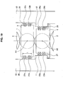
- FIG. 6 is a view schematically showing a rolling apparatus according to a first embodiment of the present invention.
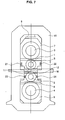
- FIG. 7 is a side view schematically showing a main body of the rolling apparatus.
- the rolling apparatus shown in FIG. 6 and FIG. 7 includes an upper work roll 1 supported by an upper work roll chock 5, an upper backup roll 3 supported by an upper backup roll chock 7, a lower work roll 2 supported by a lower work roll chock 6, and a lower backup roll 4 supported by a lower backup roll chock 8. Further, the rolling apparatus shown in FIG.
- FIG. 6 and FIG 7 includes a screw down device 9 that controls a gap between the upper and lower work rolls, and an upper drive electric motor 35 and a lower drive electric motor 36 that drive the upper and lower work rolls, respectively.
- a flat-rolled metal material M to be rolled by the rolling apparatus moves in a rolling direction F.
- FIG. 6 and FIG 7 basically show only the apparatus construction on the operator side, similar devices exist on the driving side, too.
- a housing 10 is provided with an exit side project block 11 and an entry side project block 12.
- the exit side project block 11 and the entry side project block 12 are formed so as to protrude from the housing 10 towards the inner side of the rolling apparatus.
- the rolling apparatus shown in FIG. 6 and FIG. 7 includes load detection devices detecting loads acting on the housing 10 or the project blocks 11, 12 at the time of rolling a flat-rolled metal material.
- the rolling apparatus of the present embodiment is provided with four load detection devices 21, 22, 23, and 24 on the operator side.
- the load detection devices are also provided on the driving side, the number of the detection devices being the same as the number of the detection devices on the operator side.
- An upper work roll chock exit side load detection device 21 is provided in the upper work roll chock 5 on an exit side in the rolling direction in a manner that the upper work roll chock exit side load detection device 21 faces the housing 10 on the exit side in the rolling direction.
- the upper work roll chock exit side load detection device 21 detects a force acting between the housing 10 on the exit side and the upper work roll chock 5, that is, the upper work roll chock exit side load detection device 21 detects a rolling direction force acting on the upper work roll chock 5 in the rolling direction toward the exit side.
- An upper work roll chock entry side load detection device 22 is provided in the upper work roll chock 5 on an entry side in the rolling direction in a manner that the upper work roll chock entry side load detection device 22 faces the housing 10 on the entry side in the rolling direction.
- the upper work roll chock entry side load detection device 22 detects a force acting between the housing 10 on the entry side and the upper work roll chock 5, that is, the upper work roll chock entry side load detection device 22 detects a rolling direction force acting on the upper work roll chock 5 in the rolling direction toward the entry side.
- a lower work roll chock exit side load detection device 23 is provided in the lower work roll chock 6 on an exit side in the rolling direction in a manner that the lower work roll chock exit side load detection device 23 faces the exit side project block 11 of the housing 10 on the exit side in the rolling direction.
- the lower work roll chock exit side load detection device 23 detects a force acting between the exit side project block 11 and the lower work roll chock 6, that is, the lower work roll chock exit side load detection device 23 detects a rolling direction force acting on the lower work roll chock 6 in the rolling direction toward the exit side.
- a lower work roll chock entry side load detection device 24 is provided in the lower work roll chock 6 on an entry side in the rolling direction in a manner that the lower work roll chock entry side load detection device 24 faces the entry side project block 12 of the housing 10 on the entry side in the rolling direction.
- the lower work roll chock entry side load detection device 24 detects a force acting between the entry side project block 12 and the lower work roll chock 6, that is, the lower work roll chock entry side load detection device 24 detects a rolling direction force acting on the lower work roll chock 6 in the rolling direction toward the entry side.
- FIG 8 is an enlarged schematic side view of an upper work roll chock 5 of the rolling apparatus shown in FIG. 6 and FIG. 7 and a periphery thereof.
- the positions (heights) in the draft direction of the respective load detection devices 21 and 22 for the upper work roll chock 5 are the same as the position (height) in the draft direction of a roll axis A1 of the upper work roll 1 held by the upper work roll chock 5, and the positions (heights) in the draft direction of the respective load detection devices 23 and 24 for the lower work roll chock 6 are the same as the position (height) in the draft direction of a roll axis A2 of the lower work roll 2 held by the lower work roll chock 6.
- the thus disposed load detection devices 21, 22, 23, and 24 can directly detect the rolling direction forces applied to the respective work roll chocks 5 and 6. That is, the load detection devices 21 and 22 for the upper work roll chock 5 detect a rolling direction force applied to the upper work roll chock 5 toward the exit side and a rolling direction force applied to the upper work roll chock 5 toward the entry side, respectively. Further, the load detection devices 23 and 24 for the lower work roll chock 6 detect a rolling direction force applied to the lower work roll chock 6 toward the exit side and a rolling direction force applied to the lower work roll chock 6 toward the entry side, respectively.
- the heights of the load detection devices 21 and 22 for the upper work roll chock 5 in the draft direction are the same as the height of the roll axis A1 of the upper work roll 1 in the draft direction. Accordingly, the height at which a load is applied from the upper work roll 1 to the upper work roll chock 5 is the same as the height at which a load is applied from the upper work roll chock 5 to the housing 10.
- the load detection devices 21 and 22 can each accurately detect the rolling direction force applied to the upper work roll chock 5.
- the load detection devices 21 and 22 can each accurately detect the rolling direction force applied to the upper work roll chock 5.
- the heights of the load detection devices in the draft direction of the work roll are the same as the height of the roll axis in the draft direction of the work roll, the heights may not be exactly the same.
- the point of effort of the rolling direction force may be located within a range in which the load detection device is in contact with the housing or the project block.
- only one load detection device is provided on each of the exit and entry sides of each work roll chock in the rolling direction.
- multiple load detection devices may also be disposed in a manner that the load detection devices are shifted from each other in the roll axis direction on each of the exit and entry sides of each work roll chock in the rolling direction.
- a construction of a rolling apparatus according to the present embodiment is basically the same as the construction of the rolling apparatus according to the first embodiment.
- the rolling apparatus according to the first embodiment includes load detection devices provided to each work roll chock at one certain height
- the rolling apparatus according to the present embodiment includes multiple load detection devices provided in the draft direction.
- the rolling apparatus includes eight load detection devices on the operator side. Note that the detection devices are also provided to the driving side, the number of the detection devices being the same as the number of the detection devices on the operator side.
- a first load detection device 21a and a second load detection device 21b on the exit side of the upper work roll chock are provided in the upper work roll chock 5 on the exit side in the rolling direction in a manner that the first load detection device 21 a and the second load detection device 21b face the housing 10 on the exit side in the rolling direction.
- the load detection devices 21a and 21b each detect a force acting between the housing 10 on the exit side and the upper work roll chock 5.
- the load detection device 21a and the load detection device 21b are disposed in the draft direction, one above the other.
- the load detection devices 21a and 21b are disposed in a manner that a line extending in the rolling direction and including a roll axis A1, which is a point of effort of the rolling direction force of the upper work roll 1 in the draft direction of the upper work roll 1, is interposed between the load detection devices 21a and 21b.
- the load detection device 21a is disposed above (at a position higher than the position of) the roll axis A1 of the upper work roll 1 in the draft direction, and the load detection device 21b is disposed below (at a position lower than the position of) the roll axis A1 of the upper work roll 1 in the draft direction.
- the thus constructed load detection devices 21a and 21b are connected to an upper work roll chock exit side load calculation device 31 as shown in FIG. 10 .
- the load calculation device 31 adds up a load detected by the load detection device 21 a and a load detected by the load detection device 21b.
- the total value of those detected loads corresponds to a rolling direction force applied to the housing 10 on the exit side from the upper work roll chock 5, that is, a rolling direction force of the upper work roll chock 5 toward the exit side.
- a first load detection device 22a and a second load detection device 22b on the entry side of the upper work roll chock are provided in the upper work roll chock 5 on the entry side in the rolling direction in a manner that the first load detection device 22a and the second load detection device 22b face the housing 10 on the entry side in the rolling direction.
- the load detection devices 22a and 22b each detect a force acting between the housing 10 on the entry side and the upper work roll chock 5.
- the load detection devices 22a and 22b are disposed in the draft direction, one above the other, in the same manner as the above-described load detection devices 21 a and 21b.
- the thus constructed load detection devices 22a and 22b are connected to an upper work roll chock entry side load calculation device 32 as shown in FIG. 10 .
- the load calculation device 32 adds up loads detected by the load detection devices 22a and 22b. In this way, a rolling direction force applied to the housing 10 on the entry side from the upper work roll chock 5, that is, a rolling direction force of the upper work roll chock 5 toward the entry side is calculated.
- a first load detection device 23a and a second load detection device 23b on the exit side of the lower work roll chock are provided in the lower work roll chock 6 on the exit side in the rolling direction in a manner that the first load detection device 23a and the second load detection device 23b face the housing 10 on the exit side in the rolling direction.
- the load detection devices 23a and 23b each detect a force acting between the exit side project block 11 and lower work roll chock 6.
- the load detection devices 23a and 23b are disposed in the draft direction, one above the other, in the same manner as the above-described load detection devices 21 a and 21b.
- the load detection devices 23a and 23b are connected to a lower work roll chock exit side load calculation device 33 as shown in FIG. 10 .
- the load calculation device 33 adds up loads detected by the load detection devices 23a and 23b. In this way, a rolling direction force applied to the exit side project block 11 from the lower work roll chock 6, that is, a rolling direction force of the lower work roll chock 6 towards the exit side is calculated.
- a first load detection device 24a and a second load detection device 24b on the entry side of the lower work roll chock are provided in the lower work roll chock 6 on the entry side in the rolling direction in a manner that the first load detection device 24a and the second load detection device 24b face the housing 10 on the entry side in the rolling direction.
- the load detection devices 24a and 24b each detect a force acting between the entry side project block 12 and the lower work roll chock 6.
- the load detection devices 24a and 24b are disposed in the draft direction, one above the other, in the same manner as the above-described load detection devices 21 a and 21b.
- the load detection devices 24a and 24b are connected to a lower work roll chock entry side load calculation device 34 as shown in FIG. 10 .
- the load detection device 34 adds up loads detected by the load detection devices 24a and 24b. In this way, a rolling direction force applied to the entry side project block 12 from the lower work roll chock 6, that is, a rolling direction force of the lower work roll chock 6 towards the entry side is calculated.
- both of the load detection devices 21a and 21b are disposed in the upper work roll chock 5 on the exit side in the rolling direction. Accordingly, a side surface of the exit side of the upper work roll chock 5 is supported at multiple points in the draft direction, particularly at both above and below the roll axis A1 of the upper work roll 1.
- both of the load detection devices 22a and 22b are disposed in the upper work roll chock 5 on the entry side in the rolling direction. Accordingly, a side surface of the entry side of the upper work roll chock 5 is supported at multiple points in the draft direction, particularly at both above and below the roll axis A1 of the upper work roll 1.
- the load detection devices 21a, 21b, 22a, and 22b can each accurately detect the rolling direction force applied to the upper work roll chock 5.
- the load detection devices 21a, 21b, 22a, and 22b can each accurately detect the rolling direction forces applied to the upper work roll chock 5.
- the rolling apparatus according to the present embodiment is provided with two load detection devices in the draft direction, one above the other, on each of the exit and entry sides of each work roll chock in the rolling direction.
- the number of the load detection devices is not necessarily two, and, on each of the exit and entry sides of each work roll chock in the rolling direction, there may be provided three or more load detection devices disposed in a manner that the three or more load detection devices are shifted from each other in the draft direction.
- At least one of the load detection devices be disposed above a roll axis of the corresponding work roll in the draft direction and at least one of the load detection device be disposed below a roll axis of the corresponding work roll in the draft direction all the time.
- a construction of a rolling apparatus according to the third embodiment is basically the same as the construction of the rolling apparatus according to the second embodiment.
- the rolling apparatus according to the second embodiment includes two load detection devices provided on each of the exit and entry sides of each work roll chock in the rolling direction
- the rolling apparatus according to the present embodiment includes one load detection device and one dummy block (protruding part).
- the rolling apparatus includes four load detection devices and four dummy blocks.
- An upper work roll chock exit side load detection device 21 and an upper work roll chock exit side dummy block 51 are provided on the exit side of the upper work roll chock 5 in the rolling direction.
- one of the load detection device 21 and the dummy block 51 is disposed above a roll axis A1 of the upper work roll 1 in the draft direction, and the other is disposed below the roll axis A1 in the draft direction.
- the dummy block 51 is disposed above the roll axis A1 of the upper work roll 1 in the draft direction, and the load detection device 21 is disposed below the roll axis A1 in the draft direction. That is, the load detection device 21 and the dummy block 51 are disposed so as to be shifted from each other in the draft direction, one above the other.
- the load detection device 21 is slightly protruded from the side surface of the exit side of the upper work roll chock 5, and the dummy block 51 is also slightly protruded from the side surface of the exit side of the upper work roll chock 5, the amount of protrusion being the same as the amount of protrusion of the load detection device 21.
- an upper work roll chock entry side load detection device 22 and an upper work roll chock entry side dummy block 52 are provided on the entry side of the upper work roll chock 5 in the rolling direction.
- a lower work roll chock exit side load detection device 23 and a lower work roll chock exit side dummy block 53 are provided on the exit side of the lower work roll chock 6 in the rolling direction.
- a lower work roll chock entry side load detection device 24 and a lower work roll chock entry side dummy block 54 are provided on the entry side of the lower work roll chock 6 in the rolling direction.
- the upper work roll chock exit side load detection device 21 and the upper work roll chock entry side load detection device 22 are disposed such that the height in the draft direction of the upper work roll chock exit side load detection device 21 and the height in the draft direction of the upper work roll chock entry side load detection device 22 are the same as each other.
- the upper work roll chock exit side dummy block 51 and the upper work roll chock entry side dummy block 52 are disposed such that the height in the draft direction of the upper work roll chock exit side dummy block 51 and the height in the draft direction of the upper work roll chock entry side dummy block 52 are the same as each other.
- the length in the draft direction from the load detection device 21 to the roll axis A1 of the work roll 1 and the length in the draft direction from the dummy block 51 to the roll axis A1 are fixed.
- a moment arm in the upper work roll chock 5 is fixed and is known in advance. Accordingly, in the case where a force is applied from the upper work roll 1 to the upper work roll chock 5 on the exit side in the rolling direction, for example, distribution of the loads applied to the load detection device 21 and the dummy block 51 is also fixed and is also known in advance.
- both the loads applied to the load detection device 21 and the dummy block 51 can be detected/estimated.
- the rolling direction force applied from the upper work roll chock 5 to the housing 10 can be measured.
- the load detection devices 21 and 22 can each accurately detect the rolling direction force applied to the upper work roll chock 5.
- the number of load detection devices can be reduced to half of the number of load detection devices shown in the second embodiment, the manufacturing cost can also be reduced.
- the exit side load detection devices 21 and 23 and the entry side load detection devices 22 and 24 are disposed such that the height of the exit side load detection device 21 and the height of the entry side load detection device 22 are the same as each other, and the height of the exit side load detection device 23 and the height of the entry side load detection device 24 are the same as each other.
- the load detection devices can each appropriately measure a rolling direction force even if the heights in the draft direction are shifted, and hence are not necessarily disposed at the same height.
- each load detection device and the corresponding dummy block are disposed such that the interval between the height of the load detection device and the height of the roll axis is equal to the interval between the height of the dummy block and the height of the roll axis.
- the respective intervals are known in advance and the rolling direction forces can be appropriately estimated on the basis of the outputs of the load detection devices, and hence, the intervals are not necessarily be equal to each other.
- the upper work roll chock exit side load calculation device 31 connected to the upper work roll chock exit side load detection device 21 calculates a rolling direction force on the basis of a load detected by the load detection device 21, an interval in the draft direction between the axis A1 of the upper work roll 1 and the load detection device 21, and an interval in the draft direction between the axis A1 of the upper work roll 1 and the dummy block 51.
- a construction of a rolling apparatus according to the present embodiment is basically the same as the construction of the rolling apparatus according to the first embodiment.
- each load detection device is disposed on the center of the radial bearing 5a of each work roll chock in the roll axis direction.
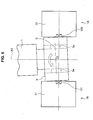
- FIG. 14 is an enlarged plan view of the upper work roll chock 5 according to the present embodiment and a periphery thereof, which is similar to the cross-sectional plan view of FIG. 5 .
- the load detection devices 21 and 22 for the upper work roll chock 5 are disposed in a manner that the positions of the load detection devices 21 and 22 in the roll axis direction are located on the center of the radial bearing 5a of the upper work roll chock 5.
- the lower work roll chock 6 may also have the load detection devices 23 and 24 arranged therein in the similar manner.
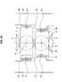
- the relative position between the load detection devices 21 and 22 and the radial bearing 5a does not change. That is, the load detection devices 21 and 22 are located on the center of the radial bearing 5a of the upper work roll chock 5 in the roll axis direction. Therefore, no moment is generated within a horizontal plane in the upper work roll chock 5. Accordingly, the rotation and the tilt of the upper work roll chock 5 can be prevented. As a result, the load detection devices 21 and 22 can accurately detect the rolling direction forces applied to the upper work roll chock 5.
- the position of the load detection device is the same as the position of the center of the radial bearing in the roll axis direction of the work roll, the positions may not be exactly the same.
- the point of effort of the rolling direction force may be located within a range in which the load detection device is in contact with the housing or the project block.
- only one load detection device is provided on each of the exit and entry sides of each work roll chock in the rolling direction.
- multiple load detection devices may also be disposed in a manner that the load detection devices are shifted from each other in the roll axis direction on each of the exit and entry sides of each work roll chock in the rolling direction.
- the rolling apparatus according to the present embodiment can be combined with the rolling apparatuses according to the first to third embodiments.
- the position in the draft direction of each of the load detection devices is the same as the position in the draft direction of the roll axis of a corresponding one of the work rolls supported by a corresponding one of the work roll chocks, the roll axis being the center of the radial bearing of the work roll chock in the roll axis direction.
- a construction of a rolling apparatus according to the present embodiment is basically the same as the construction of the rolling apparatus according to the fourth embodiment.
- the rolling apparatus according to the fourth embodiment includes only one load detection device on the center of the radial bearing of the work roll chock in the roll axis direction
- the rolling apparatus according to the present embodiment includes multiple load detection devices disposed in a manner that the load detection devices are shifted from each other in the roll axis direction.
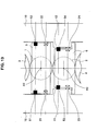
- a first load detection device 21a and a second load detection device 21b on the exit side of the upper work roll chock are provided in the upper work roll chock 5 on the exit side in the rolling direction in a manner that the first load detection device 21a and the second load detection device 21b face the housing 10 on the exit side in the rolling direction.
- the load detection devices 21a and 21b each detect a force acting between the housing 10 on the exit side and the upper work roll chock 5.
- the load detection devices 21a and 21b are arranged in the roll axis direction.
- the load detection device 21 a is disposed at an inner side (to which the work roll 1 extends) with respect to the center C of the radial bearing 5a of the upper work roll chock 5 in the roll axis direction.
- the load detection device 21b is disposed at an outer side (opposite to which the work roll 1 extends) with respect to the center C of the radial bearing 5a in the roll axis direction.
- a first load detection device 22a and a second load detection device 22b on the entry side of the upper work roll chock are provided in the upper work roll chock 5 on the entry side in the rolling direction in a manner that the first load detection device 22a and the second load detection device 22b face the housing 10 on the entry side in the rolling direction.
- the load detection devices 22a and 22b each detect a force acting between the housing 10 on the entry side and the upper work roll chock 5.
- the load detection device 22a and the load detection device 22b are arranged in the roll axis direction. Note that, although only the upper work roll chock 5 is shown in FIG. 15 , the lower work roll chock 6 may also have load detection devices 23a, 23b, 24a, and 24b disposed therein in the similar manner.
- the side surface of the exit side of the upper work roll chock 5 is supported all the time at multiple points in the roll axis direction in a manner that the center C of the radial bearing 5a, which is a point of effort of the rolling direction force in the roll axis direction, is interposed between the points.
- the side surface of the exit side of the upper work roll chock 5 is supported by the load detection devices 21a and 21b in a manner that the center C of the radial bearing 5a of the upper work roll chock 5 in the roll axis direction is interposed between the load detection devices 21a and 21b.
- a side surface of the entry side of the upper work roll chock 5 is also supported all the time at multiple points in the roll axis direction in a manner that the center C of the radial bearing 5a, which is a point of effort of the rolling direction force in the roll axis direction, is interposed between the points.
- the side surface of the entry side of the upper work roll chock 5 is supported by the load detection devices 22a and 22b in a manner that the center C of the radial bearing 5a of the upper work roll chock 5 in the roll axis direction is interposed between the load detection devices 22a and 22b.
- the load detection devices 21a, 21b, 22a, and 22b can each accurately detect the rolling direction force applied to the upper work roll chock 5.
- the rolling apparatus according to the present embodiment is provided with two load detection devices in the roll axis direction on each of the exit and entry sides of each work roll chock in the rolling direction.
- the number of the load detection devices is not necessarily be two, and, on each of the exit and entry sides of each work roll chock in the rolling direction, there may be provided three or more load detection devices disposed in a manner that the three or more load detection devices are shifted from each other in the roll axis direction.
- the rolling apparatus according to the present embodiment can be combined with the rolling apparatuses according to the first to third embodiments.
- multiple load detection devices are disposed in multiple rows in the roll axis direction and multiple rows in the draft direction on each of the exit and entry sides of each work roll chock in the rolling direction.
- a construction of a rolling apparatus according to the present embodiment is basically the same as the construction of the rolling apparatus according to the fifth embodiment.
- the rolling apparatus according to the fifth embodiment includes two load detection devices on each of the exit and entry sides of each work roll chock in the rolling direction
- the rolling apparatus according to the present embodiment includes one load detection device and one dummy block (protruding part) in the same manner as the third embodiment.
- the rolling apparatus includes two load detection devices and two dummy blocks in each work roll chock.
- an upper work roll chock exit side load detection device 21 a and an upper work roll chock exit side dummy block 51 are provided on the exit side of the upper work roll chock 5 in the rolling direction.
- one of the load detection device 21 a and the dummy block 51 is disposed at one side with respect to the center C of the radial bearing 5a in the roll axis direction, and the other is disposed at the other side with respect to the center C of the radial bearing 5a in the roll axis direction.
- FIG. 16 an upper work roll chock exit side load detection device 21 a and an upper work roll chock exit side dummy block 51 are provided on the exit side of the upper work roll chock 5 in the rolling direction.
- one of the load detection device 21 a and the dummy block 51 is disposed at one side with respect to the center C of the radial bearing 5a in the roll axis direction, and the other is disposed at the
- the load detection device 21 is disposed at an inner side with respect to the center C of the radial bearing 5a in the roll axis direction, and the dummy block 51 is interposed at an outer side with respect to the center C of the radial bearing 5a in the roll axis direction. That is, the load detection device 21 a and the dummy block 51 are arranged in the roll axis direction.
- an upper work roll chock entry side load detection device 22a and an upper work roll chock entry side dummy block 52 are provided on the entry side of the upper work roll chock 5 in the rolling direction.
- the load detection device 21a is slightly protruded from the side surface of the exit side of the upper work roll chock 5, and the dummy block 51 is also slightly protruded from the side surface of the exit side of the upper work roll chock 5, the amount of protrusion being the same as the amount of protrusion of the load detection device 21 a.
- the load detection device 22a is slightly protruded from the side surface of the entry side of the upper work roll chock 5, and the dummy block 52 is also slightly protruded from the side surface of the entry side of the upper work roll chock 5, the amount of protrusion being the same as the amount of protrusion of the load detection device 22a.
- the upper work roll chock exit side load detection device 21a and the upper work roll chock entry side load detection device 22a are disposed such that the position in the roll axis direction of the upper work roll chock exit side load detection device 21 a and the position in the roll axis direction of the upper work roll chock entry side load detection device 22a are the same as each other.
- the upper work roll chock exit side dummy block 51 and the upper work roll chock entry side dummy block 52 are disposed such that the position in the roll axis direction of the upper work roll chock exit side dummy block 51 and the position in the roll axis direction of the upper work roll chock entry side dummy block 52 are the same as each other.
- the upper work roll chock exit side load calculation device 31 connected to the upper work roll chock exit side load detection device 21 a calculates a rolling direction force on the basis of a load detected by the load detection device 21 a, an interval in the roll axis direction between the center C of the radial bearing 5a provided to the upper work roll chock 5 and the load detection device 21a, and an interval in the draft direction between the center C of the radial bearing 5a provided to the upper work roll chock 5 and the dummy block 51.
- the rolling apparatuses according to the embodiments may also have the following constructions.
- the side surfaces of the upper work roll chock 5 face the housing 10 on which the project blocks 11 and 12 are not disposed, and the side surfaces of the lower work roll chock 6 face the project blocks 11 and 12.
- the main body of the rolling apparatus may not necessarily have such a construction.
- the side surfaces of both the work roll chocks 5 and 6 may have the construction in which the side surfaces of both the work roll chocks 5 and 6 face the project blocks 11 and 12.
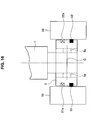
- FIG. 18 shows a rolling apparatus in which three load detection devices 21a, 21b, and 21c are disposed in the upper work roll chock 5 on the exit side of the upper work roll chock 5 in the rolling direction, and three load detection devices 22a, 22b, and 22c are disposed in the upper work roll chock 5 on the entry side of the upper work roll chock 5 in the rolling direction.
- the load detection devices 21 a, 21 b, and 21c on the exit side in the rolling direction are disposed in a manner that the load detection devices 21 a, 21b, and 21c are arranged in the draft direction, and in the same manner, the load detection devices 22a, 22b, and 22c on the entry side in the rolling direction are disposed in a manner that the load detection devices 22a, 22b, and 22c are arranged in the draft direction.
- the thus constructed rolling apparatus when the roll gap between the upper work roll 1 and the lower work roll 2 is small, all load detection devices face the project blocks 11 and 12. Accordingly, a rolling direction force is calculated on the basis of the loads detected by all those load detection devices.
- the load detection devices 21 a and 22a which are disposed uppermost, do not face the project blocks 11 and 12 anymore. However, even in this case, the load detection devices 21b, 21c, 22b, and 22c still face the project blocks 11 and 12. Consequently, the rolling direction force can be calculated on the basis of the load detected by the load detection devices facing the project blocks 11 and 12. That is, the thus constructed rolling apparatus can accurately measure the rolling direction force even if the roll gap increases.
- one or more load detection devices are provided on each of the entry and exit sides of the upper and lower work roll chocks 5 and 6 in the rolling direction.
- one or more load detection devices may not be provided on each of all the entry and exit sides of the upper and lower work roll chocks 5 and 6 in the rolling direction.
- one or more load detection devices may be provided only on the exit side of the upper work roll chock 5 in the rolling direction, or one or more load detection devices may be provided only on the exit side of the lower work roll chock 6 in the rolling direction.
- one or more load detection devices may be provided only on the entry side and the exit side of the upper work roll chock 5 in the rolling direction, or one or more load detection devices may be provided only on the entry side and the exit side of the lower work roll chock 6 in the rolling direction.
- each load detection device is connected to an antenna provided to each work roll chock, and the load calculation device is connected to a receiver.
- the detection signal of the load detection device is subjected to appropriate modulation processing and is input to the antenna.
- the detection signal is sent as a radio wave to the outside of the work roll chock from the antenna, and the radio wave is received by the receiver.
- the detection signal is transmitted to the load calculation device.
- the type of radio communication may be any. Examples of the radio communication means include communication based on a near field communication standard, such as Bluetooth (registered trademark), and communication performed using a wireless LAN, infrared data communication, or the like.
- the load detection device transmits the detection signal via radio, and thus, the detection signal of the load detection device can be transmitted easily at high speed on a real-time basis, with a simple and small construction.
- limitations related to device arrangement are reduced, such as position relationship between devices (load detection devices, bending devices, and the like) provided to the roll chocks and the project blocks. That is, the wiring for connecting each load detection device to a load calculation device is not necessary, and hence, wire routing that complicatedly passing around the wiring in order not to interfere the rolling apparatus-in-operation is not necessary. Those are extremely helpful for improving operation environment and reducing cost.
- the second embodiment and the fifth embodiment may be provided with covers 25, 26, 27, and 28 each covering surfaces of two adjacent load detection devices.
- covers 25, 26, 27, and 28 each covering surfaces of two adjacent load detection devices.
- parts for fixing the covers and waterproofing treatment for preventing water from entering into the inner side of the load detection device are not shown in FIG. 19 .
- the upper work roll chock 5 is supported by the cover 25 covering the load detection devices 21a and 21b and the cover 26 covering the load detection devices 22a and 22b.
- the lower work roll chock 6 is supported by the cover 27 covering the load detection devices 23a and 23b and the cover 28 covering the load detection devices 24a and 24b.
- the covers 25, 26, 27, and 28 may also be provided to the load detection devices 21, 22, 23, and 24, respectively, as in the first embodiment. Also in this case, with increase in the lengths of the covers, the areas being in contact with the side surfaces of the roll chock 5 and the project block 12 increase. Accordingly, even in the case where the positions of the load detection devices 21, 22, 23, and 24 shift in the draft direction with respect to the position of the roll axis A1 of the work roll 1 or the position of the roll axis 2A of the work roll 2, the same effect of the work roll chock-tilt prevention can be obtained by providing the covers to the load detection devices.
- a rolling apparatus which includes at least three load detection devices on at least one of the entry side in the rolling direction and the exit side of the rolling direction, and in which the at least three load detection devices are disposed in a manner that they shift in at least one of the draft direction and the roll axis direction of the work rolls.
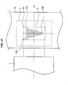
- each load detection device is disposed so as to be shifted in one of the draft direction and the roll axis direction of the work rolls, in a manner that the point of effort of the rolling direction force of each of the work rolls is located within an area defined by connecting the load detection devices.
- three load detection devices 22a, 22b, and 22c are disposed in a triangular shape, and thus, a movement in a tilting manner of the work roll chock 5 can be prevented and the rolling direction force can be detected with high accuracy.
- two load detection devices 22a and 22c are disposed above the roll axis A1 of the work roll 1 in the draft direction, and the load detection device 22b is disposed below the roll axis A1 of the work roll 1 in the draft direction.
- two load detection devices 22a and 22c disposed above the roll axis A1 are disposed in a manner that the center C of a radial bearing 5a, which is a point of effort of the rolling direction force in the roll axis direction, is interposed between the load detection devices 22a and 22c.
- the point of effort of the rolling direction force is located within an area S having a triangular shape defined by connecting the three load detection devices 22a, 22b, and 22c. Accordingly, even if the work roll 1 moves in the draft direction or in the roll axis direction, at least two load detection devices are always supporting the work roll chock 5 in the state of interposing therebetween the point of effort of the rolling direction force, and thus, the tilt of the work roll chock 5 can be prevented.
- the area in which the point of effort of the rolling direction force is to be located is not limited to the area having a triangular shape formed by disposing three load detection devices 22a, 22b, and 22c.
- the area may be an area S having a quadrilateral shape formed by four load detection devices 22a, 22b, 22c, and 22d, in which the roll axis is interposed between two load detection devices in the draft direction and the center of the radial bearing is interposed between two load detection devices in the roll axis direction.
- the shape may be a trapezium, a rhombus, or other polygons, that can be formed by disposing multiple load detection devices.
- the upper work roll chock exit side load detection device 21 and the upper work roll chock entry side load detection device 22 are connected to an upper work roll chock rolling direction force calculation device 41.
- the upper work roll chock rolling direction force calculation device 41 calculates a difference between a load detected by the upper work roll chock exit side load detection device 21 and a load detected by the upper work roll chock entry side load detection device 22, and, on the basis of the calculation result, calculates the rolling direction force acting on the upper work roll chock 5.
- the upper work roll chock exit side load calculation device 31 and the upper work roll chock entry side load calculation device 32 are connected to an upper work roll chock rolling direction force calculation device 41.
- the upper work roll chock rolling direction force calculation device 41 calculates a difference between a calculation result obtained by the upper work roll chock exit side load calculation device 31 and a calculation result obtained by the upper work roll chock entry side load calculation device 32, and, on the basis of the calculation result, calculates the rolling direction force acting on the upper work roll chock 5.
- the lower work roll chock exit side load detection device 23 and the lower work roll chock entry side load detection device 24 are connected to a lower work roll chock rolling direction force calculation device 42.
- the lower work roll chock rolling direction force calculation device 42 calculates a difference between a load detected by the lower work roll chock exit side load detection device 23 and a load detected by the lower work roll chock entry side load detection device 24, and, on the basis of the calculation result, calculates the rolling direction force acting on the lower work roll chock 6.
- the lower work roll chock exit side load calculation device 33 and the lower work roll chock entry side load calculation device 34 are connected to a lower work roll chock rolling direction force calculation device 42.
- the lower work roll chock rolling direction force calculation device 42 calculates a difference between a calculation result obtained by the lower work roll chock exit side load calculation device 33 and a calculation result obtained by the lower work roll chock entry side load calculation device 34, and, on the basis of the calculation result, calculates the rolling direction force acting on the lower work roll chock 6.
- the upper work roll chock rolling direction force calculation device 41 and the lower work roll chock rolling direction force calculation device 42 are connected to an operator side work roll chock rolling direction force calculation device 43.
- the operator side work roll chock rolling direction force calculation device 43 calculates the sum of the calculation result of the upper work roll chock rolling direction force calculation device 41 and the calculation result of the lower work roll chock rolling direction force calculation device 42, to calculate the rolling direction resultant force acting on the upper work roll 1 and the lower work roll 2 on the operator side.
- the calculation processing described above is conducted not only for the operator side but also for the driving side by using entirely the same device construction (not shown), and the rolling direction resultant force acting on the upper work roll 1 and the lower work roll 2 on the driving side is calculated by a driving side work roll chock rolling direction force calculation device 44.
- an operator side/driving side rolling direction force calculation device 45 calculates the difference between the calculation results on the operator side and the calculation results on the driving side, and in this way, the difference of the rolling direction forces acting on the upper and lower work roll chocks between the operator side and the driving side is calculated.
- a control quantity calculation device 46 sets the difference of the rolling direction forces acting on the work roll chocks 5 and 6 between the operator side and the driving side to a suitable target value and calculates a left-right swivelling component control quantity of the roll gap of the rolling mill on the basis of the calculation result of the difference of the rolling direction forces between the operator side and the driving side for preventing the camber.
- the control quantity is calculated by PID calculation that takes a proportional (P) gain, an integration (I) gain, and a differential (D) gain into consideration, for example, on the basis of the left-right difference of the rolling direction force.
- a control device 47 controls the left-right swivelling component of the roll gap of the rolling mill on the basis of this control quantity calculation result. In this way, rolling free from the occurrence of camber or having extremely slight camber can be accomplished.
- the operator side work roll chock rolling direction force calculation device 43 calculates the difference between the calculation result of the upper work roll chock rolling direction force calculation device 41 and the calculation result of the lower work roll chock rolling direction force calculation device 42, to calculate the difference of the rolling direction forces acting on the work roll chocks on the operator side between the upper side and the lower side.
- the calculation processing described above is conducted not only for the operator side but also for the driving side by using entirely the same device construction (not shown), and the difference of the rolling direction forces acting on the work roll chocks on the driving side between the upper side and the lower side is calculated by the driving side work roll chock rolling direction force calculation device 44.
- the operator side/driving side rolling direction force calculation device 45 totalizes the calculation results on the operator side and the calculation results of the driving side (difference between the upper side and the lower side), and in this way, the difference of the rolling direction forces acting on the work roll chocks between the upper side and the lower side is calculated.
- control quantity calculation device 46 sets the difference of the rolling direction forces acting on the work roll chocks between the upper side and the lower side to a suitable target value and calculates an upper side-lower side swivelling component control quantity of a roll speed of the rolling mill on the basis of the calculation result of the difference of the rolling direction forces between the upper side and the lower side for preventing the warp.
- control quantity is calculated by PID calculation that takes a proportional (P) gain, an integration (I) gain, and a differential (D) gain into consideration, for example, on the basis of the upper side-lower side rolling direction force.
- control device 47 controls the upper side-lower side swivelling component control quantity of the roll speed of the upper drive electric motor 35 and the lower drive electric motor 36 of the rolling mill on the basis of this control quantity calculation result. In this way, rolling free from the occurrence of warp or having extremely slight warp can be accomplished.
- the roll speed of the rolling mill is used here as the upper side-lower side swivelling component control quantity
- a frictional coefficient between a rolling roll and a material to be rolled a difference in temperature of a material to be rolled between the upper surface and the lower surface, an angle of incidence of a material to be rolled, a position of the work roll chock in the horizontal direction, top and bottom rolling torques, or the like may be also used.
- the operator side/driving side rolling direction force calculation device 45 calculates the difference between the calculation results on the operator side and the calculation results on the driving side, and in this way, calculates the difference of the rolling direction forces acting on the work roll chocks between the operator side and the driving side.
- the hydraulic screw down devices 9 are operated simultaneously on the operator side and on the driving side and are tightened until the sum of right and left counterforces of a backup roll is equal to a preset value (zero point adjustment load), and, under that state, leveling operation for rendering the difference of the rolling direction forces between the operator side and the driving side zero is executed.
- the control quantity calculation device 46 calculates the control quantity of the hydraulic screw down device 9 such that the difference of the rolling direction forces acting on the work roll chocks 5 and 6 between the operator side and the driving side become zero and that the zero point adjustment load is maintained, on the basis of the results of the difference of the rolling direction forces between the operator side and the driving side (difference between the operator side and the driving side) calculated by the operator side/driving side rolling direction force calculation device 45. Then, the control device 47 controls the reduction position of a roll of the rolling mill on the basis of the control quantity calculation result. In this way, the difference of the rolling direction forces acting on the work roll chocks between the operator side and the driving side is set to zero, and the reduction position at that point is set as the zero point of the reduction position of the operator side and the driving side individually.
Landscapes
- Engineering & Computer Science (AREA)
- Mechanical Engineering (AREA)
- Control Of Metal Rolling (AREA)
- Force Measurement Appropriate To Specific Purposes (AREA)
- Metal Rolling (AREA)
Abstract
Description
- The present invention relates to a rolling apparatus for flat-rolled metal materials.
- In a rolling process of a flat-rolled metal material, it is very important to roll a sheet material in a form free from camber, or in a form not having bend in the left-right direction, in order to avoid not only a plane shape defect and a dimensional accuracy defect of the rolled material but also to avoid sheet pass troubles such as a zigzag movement and a tail crash.
- Further, a warp that occurs at the time of rolling a sheet material also has a large influence on productivity of products, such as reduction in rolling efficiency and increase in the number of refining processes. For example, as for the refining processes, there are cases where it is necessary to correct camber or a warp using a leveler or by performing pressing or the like, and in an extreme case, a defect part may have to be cut. Still further, in the case where camber or a warp occurred to a large extent, the rolling facility may be damaged due to the collision of the sheet. In this case, it is not only that the sheet itself loses the product value, but that it brings about tremendous damages such as production interruption and repairing of the rolling facility.
- In addition, in order to control the above camber with high accuracy, it is also important to perform an initial setting called zero point adjustment. The zero point adjustment is performed as follows: kiss-roll tightening is conducted by operating a screw down device in a roll-rotating state; and, a point in which a measurement value of a rolling load corresponding to a preset zero point adjustment load (preset to rated load of 15% to 85%) is set as a zero point of a reduction position, and the reduction position is set as a starting point (reference) in reduction control. In this case, the difference between left and right reduction positions, that is, the zero point of reduction leveling is often adjusted simultaneously. Also, as for the zero point adjustment of the reduction leveling, the measurement values of the rolling load on the time of kiss-roll tightening on the operator side and the driving side are adjusted such that the measurement values correspond to the preset zero point adjustment load. Note that the kiss-roll tightening means that, under the state that a rolled material is not present, the upper and lower work rolls are brought into contact with each other and a load is applied between the rolls.
- Incidentally, to simplify expressions, the operator side and the driving side of the rolling mill, as the right and left sides when the rolling mill is seen from the front of the rolling direction, will be referred to as "right and left", respectively.
- In view of the problems attributed to such camber,
Patent Document 1 suggests a rolling method and a rolling apparatus capable of stably producing a flat-rolled metal material free from camber or having an extremely light camber. Specifically, in the rolling method and the rolling apparatus described inPatent Document 1, a load detection device measures a rolling direction force acting on roll chocks on an operator side and a driving side of a work roll, and a calculation device calculates a difference of the rolling direction forces between the operator side and the driving side. Then, a control device controls a left-right swivelling component of a roll gap of a rolling mill such that the difference becomes zero. - In view of the problem of a warp,
Patent Document 2 suggests a rolling method and a rolling apparatus capable of stably producing a flat-rolled metal material having an extremely light warp. Specifically, in the rolling method and the rolling apparatus described inPatent Document 2, load detection devices provided on both entry side and exit side of upper and lower roll chocks of work rolls measure rolling direction forces acting on the upper and lower work roll chocks. Then, a calculation device calculates a difference between the rolling direction force on the upper side and the rolling direction force on the lower side, that is, an upper and lower rolling direction force difference. After that, upper and lower asymmetric components of the rolling apparatus is controlled such that the upper and lower rolling direction force difference is decreased. - In view of the problem of zero point adjustment, in
Patent Document 3, it is discovered that a rolling direction force occurs even with zero point adjustment by the kiss roll state, pointed out that the rolling direction force does not affect a roll thrust force, and accordingly, there is proposed a method enabling more precise initial reduction position adjustment (reduction zero point adjustment) of a rolling mill. - Further, in order to produce a flat-rolled metal material free from camber, in a rolling method and a rolling apparatus described in
Patent Document 4, rolling direction forces acting on roll chocks on an operator side and a driving side of a work roll are measured, a difference of the rolling direction forces between the operator side and the driving side is calculated, a left-right swivelling component of a roll gap of the rolling mill is controlled by using control gain such that the difference become a control target value, and the control gain is changed depending on a condition during rolling. - Still further,
Patent Document 5 suggests a rolling mill and a rolling method capable of producing a flat-rolled metal material free from camber or warp, achieving zero point adjustment with high accuracy, and easily achieving application of a strong roll bending force. In the rolling mill and the rolling method described inPatent Document 5, a work roll chock is pressed against a contact surface with a housing window or a project block of the rolling mill in a rolling direction. Then, a load detection device measures rolling direction forces acting on roll chocks on an operator side and a driving side of a work roll, and a calculation device a calculation device calculates a difference of the rolling direction forces between the operator side and the driving side. A control device calculates left-right swivelling component control quantity of a roll gap of the rolling mill such that the difference become a control target value, and controls the roll gap on the basis of the calculated value of the left-right swivelling component control quantity of the roll gap. - Here, in any of the rolling methods and the rolling apparatuses described in the
above Patent Documents 1 to 5, the rolling direction forces are measured. Accordingly, with reference toFIG. 1 , the measurement of the rolling direction forces according toPatent Documents 1 to 5 will be described specifically.FIG. 1 is a view schematically showing a rolling apparatus. - The rolling apparatus shown in
FIG. 1 includes anupper work roll 1 supported by an upperwork roll chock 5, anupper backup roll 3 supported by an upperbackup roll chock 7, alower work roll 2 supported by a lowerwork roll chock 6, and alower backup roll 4 supported by a lowerbackup roll chock 8. Theupper backup roll 3 is disposed on the upper side of theupper work roll 1 in contact with theupper work roll 1. In the same manner, thelower backup roll 4 is disposed on the lower side of thelower work roll 2 in contact with thelower work roll 2. Further, the rolling apparatus shown inFIG. 1 includes a screw downdevice 9 that applies a rolling load to theupper work roll 1. A flat-rolled metal material M to be rolled by the rolling apparatus moves in a rolling direction F between theupper work roll 1 and thelower work roll 2. - Though
FIG. 1 basically shows only the apparatus construction on the operator side, similar devices exist on the driving side, too. - The rolling direction force acting on the
upper work roll 1 of the rolling apparatus is basically supported by the upperwork roll chock 5. Between the upperwork roll chock 5 and a housing or a project block, there are provided an upper work roll chock exit sideload detection device 121 on an exit side of the upperwork roll chock 5 in the rolling direction, and an upper work roll chock entry sideload detection device 122 on an entry side of the upperwork roll chock 5 in the rolling direction. The upper work roll chock exit sideload detection device 121 can detect the force acting between the member such as the housing or the project block and the upperwork roll chock 5 on the exit side of the upperwork roll chock 5 in the rolling direction. The upper work roll chock entry sideload detection device 122 can detect the force acting between the member such as the project block and the upperwork roll chock 5 on the entry side of the upperwork roll chock 5 in the rolling direction. To simplify the device construction, thoseload detection devices - The upper work roll chock exit side
load detection device 121 and the upper work roll chock entry sideload detection device 122 are connected to an upper work roll rolling directionforce calculation device 141. The upper work roll rolling directionforce calculation device 141 calculates a difference between a load detected by the upper work roll chock exit sideload detection device 121 and a load detected by the upper work roll chock entry sideload detection device 122, and, on the basis of the calculation result, calculates the rolling direction force acting on the upperwork roll chock 5. - In the same manner, as for the
lower work roll 2, between the lowerwork roll chock 6 and the housing or the project block, there are provided an lower work roll chock exit sideload detection device 123 on an exit side of the lowerwork roll chock 6 in the rolling direction, and a lower work roll chock entry sideload detection device 124 on an entry side of the lowerwork roll chock 6 in the rolling direction. The lower work roll chock exit sideload detection device 123 and the lower work roll chock entry sideload detection device 124 are connected to a lower work roll rolling directionforce calculation device 142. The lower work roll rolling directionforce calculation device 142 calculates, on the basis of measurement values obtained by thoseload detection devices work roll chock 6 in the same manner as in theupper work roll 1. -
- [Patent Document 1]
WO2004/082860 - [Patent Document 2]
JP 2007-260775A - [Patent Document 3]
WO2011/129453 - [Patent Document 4]
JP 2006-82118A - [Patent Document 5]
JP 2012-148339A - Here, taking into consideration the drawings on the figures in
Patent Documents 1 to 5 and technical common knowledge in the field of rolling, a load detection device is normally a load cell. Considering that work roll chocks are moved and changed during working, the load cell is generally attached to a member that faces the work roll chock in a rolling direction, such as a project block or a housing. -
FIG. 2 is an enlarged side view of the work roll chocks of the rolling apparatus shown inFIG. 1 and a periphery thereof, and shows an example in which load detection devices are attached to project blocks. In the example shown inFIG. 2 , ahousing 10 is provided with an exitside project block 11 and an entryside project block 12. The exitside project block 11 and the entryside project block 12 are formed so as to protrude from thehousing 10 towards the inner side of the rolling apparatus. - In the example shown in
FIG. 2 , the upper work roll chock exit sideload detection device 121 and the lower work roll chock exit sideload detection device 123 are provided on the exitside project block 11. On the other hand, the upper work roll chock entry sideload detection device 122 and the lower work roll chock entry sideload detection device 124 are provided on the entryside project block 12. Note that, although a protection cover or waterproofing for preventing water or the like entering inside the device is generally provided on the surface of the load detection device, they are not shown in the figure. -
FIG. 2 also shows an example of a kiss-roll tightening state. As shown inFIG. 2 , each of theload detection devices load detection devices work roll chock 5 and the distances that theload detection devices work roll chock 6 are small. - Here, in the example shown in
FIG. 2 , the positions (heights) of the respectiveload detection devices work roll 1 held by thework roll chock 5 in the draft direction, and the positions (heights) of the respectiveload detection devices work roll 2 held by thework roll chock 6 in the draft direction. In this case, rolling direction forces applied to thework roll chocks load detection devices - However, as shown in
FIG. 3 , for example, when theupper work roll 1 moves upward in the draft direction and a gap between the work rolls 1 and 2 increases, the height of the position of the roll axis A1 of theupper work roll 1 in the draft direction is larger than the heights of the positions of the upper work roll chock exit sideload detection device 121 and the upper work roll chock entry sideload detection device 122 in the draft direction. Accordingly, when the rolling direction force is applied to the upper work roll chock 5 from theupper work roll 1, the moment acts on the upperwork roll chock 5, and thus, the upper work roll chock 5 rotates in a direction indicated by the arrow shown inFIG. 3 . As a result, the upper work roll chock 5 tilts, and parts on the side surfaces of the upper work roll chock 5 come into contact with the project blocks 11, 12, and the like. - In this way, when parts on the side surfaces of the upper work roll chock 5 come into contact with the project blocks 11, 12, and the like, some of the rolling direction force applied to the upper work roll chock 5 from the
upper work roll 1 is applied to the parts at which the upper work roll chock 5 comes into contact with the project blocks 11 and 12. Accordingly, it may not be possible for theload detection devices - Further, for example, as shown in
FIG. 4 , when the work rolls 1 and 2 and the backup rolls 3 and 4 are worn away, and thus decrease in the roll diameters, the upperwork roll chock 5 and the lower work roll chock 6 move downward in the draft direction. When the upperwork roll chock 5 and the lower work roll chock 6 move downward, the height of the position of the axis A1 of thework roll 1 in the draft direction is smaller than the heights of the positions of the work roll chock exit sideload detection device 121 and the work roll chock entry sideload detection device 122, and the height of the position of the axis A2 of thework roll 2 in the draft direction is smaller than the heights of the positions of the work roll chock exit sideload detection device 123 and the work roll chock entry sideload detection device 124. Also in this case, in the same manner as the case shown inFIG. 3 , thework roll chocks work roll chocks load detection devices - Further,
FIG. 5 is a cross-sectional plan view taken along the line VI-VI ofFIG. 2 , showing the work roll chocks and a periphery thereof. As can be seen fromFIG. 5 , theload detection devices load detection devices work roll chocks - That is, for example, as shown in
FIG. 5 , when thelower work roll 2 moves owing to roll shifting for a shift quantity D in the roll axis direction, it means that the center of a bearing (hereinafter, also referred to as "radial bearing") 5a to which force in a radial direction of the upper work roll chock 5 is applied shifts in the roll axis direction with respect to the positions of theload detection devices FIG. 5 , a line C shows a line of the center of theradial bearing 5a of the upperwork roll chock 5. Accordingly, the moment acts on the upperwork roll chock 5, and thus, the upper work roll chock 5 rotates in a direction indicated by an arrow shown inFIG. 5 . As a result, the upper work roll chock 5 tilts, and parts on the side surfaces of the upper work roll chock 5 come into contact with the project blocks 11 and 12. - In this way, when parts on the side surfaces of the upper work roll chock 5 come into contact with the project blocks 11, 12, and the like, some of the rolling direction force applied to the upper work roll chock 5 from the
upper work roll 1 is applied to the parts at which the upper work roll chock 5 comes into contact with the project blocks 11 and 12. Accordingly, it may not be possible for theload detection devices - The present invention has been made in view of the circumstances described above, and an object of the present invention is to provide a rolling apparatus capable of accurately detecting a rolling direction force applied to a work roll chock.
- The inventors of the present invention have conducted studies on rolling apparatuses having various structures, with regard to detection of the rolling direction force applied to the work roll chock.
- As a result, the inventors have found that in the case where a load detection device, that is, a load cell, is provided not on a housing but on a work roll chock, the work roll chock is less likely to tilt. Note that a load detection device according to the present invention mainly represents a load cell, and may also be a device of a strain gauge, a magnetostriction type, a capacitance type, a gyro type, a hydraulic type, a piezoelectric type, or the like.
- The present invention has been achieved on the basis of the above findings, and the summary is as follows.
- (1) A rolling apparatus for a flat-rolled metal material, the rolling apparatus having at least a pair of upper and lower work rolls and a pair of upper and lower backup rolls, the rolling apparatus including:
- a pair of work roll chocks configured to hold the respective work rolls;
- housings or project blocks configured to hold the work roll chocks; and
- one or more load detection devices provided in one of the work roll chocks, the load detection devices each detecting a load acting on one of the work roll chocks on at least one of an entry side in a rolling direction and an exit side in the rolling direction,
- wherein the load detection devices are each disposed so as to face one of the housings or one of the project blocks using a point of effort of a rolling direction force of one of the work rolls as a reference, such that a rotation moment generated on each of the work roll chocks caused by the rolling direction force is equal to a counter rotation moment generated by counterforce against the rotation moment.
- (2) The rolling apparatus according to (1),
wherein the load detection devices are disposed in a manner that heights of the load detection devices in a draft direction are identical to a height of a roll axis of a corresponding one of the work rolls in the draft direction, the roll axis being the point of effort of the rolling direction force of the work roll, or that the load detection devices are located within a range in which the load detection devices are each in contact with one of the housings or one of the project blocks. - (3) The rolling apparatus according to (1),
wherein the load detection devices are disposed in a manner that, on all occasions, a line extending in the rolling direction and including a roll axis of one of the work rolls is interposed between at least two of the load detection devices in a draft direction of the work roll, the roll axis being the point of effort of the rolling direction force of the work roll, and that the load detection devices each face one of the housings or one of the project blocks. - (4) The rolling apparatus according to (3),
wherein at least one of a plurality of the load detection devices is disposed at a position higher than a position of a roll axis of one of the work rolls held by a corresponding one of the work roll chocks, the load detection devices being arranged in a manner that the load detection devices are shifted from each other in the draft direction of the work roll, and
wherein at least one of the plurality of the load detection devices is disposed at a position lower than the position of the roll axis of the one of the work rolls held by the corresponding one of the work roll chocks, the load detection devices being arranged in a manner that the load detection devices are shifted from each other in the draft direction of the work roll. - (5) The rolling apparatus according to any one of (1) to (4), further including:
- a load calculation device configured to calculate a rolling direction force by adding up loads detected by a plurality of the load detection devices provided on the entry side in the rolling direction or the exit side in the rolling direction.
- (6) The rolling apparatus according to any one of (1) to (4),
wherein the load detection devices are disposed in a manner that the load detection devices each protrude from a side surface of a corresponding one of the work roll chocks facing one of the housings or one of the project blocks, and
wherein, on the side surface of the work roll chock from which each of the load detection devices protrude, a protruding part is provided at a position shifted from the load detection device in the draft direction of the work roll. - (7) The rolling apparatus according to (6),
wherein a load detection device disposed on the entry side in the rolling direction and a load detection device disposed on the exit side in the rolling direction are located at an identical height with each other in the draft direction of the work roll, and
wherein a protruding part disposed on the entry side in the rolling direction and a protruding part disposed on the exit side in the rolling direction, the protruding parts being disposed in a corresponding manner to the respective load detection devices, are located at an identical height with each other in the draft direction of the work roll. - (8) The rolling apparatus according to (6) or (7), further including:
- a load calculation device configured to calculate a rolling direction force on a basis of a load detected by each of the load detection devices, an interval in the draft direction between an axis of a corresponding one of the work rolls held by a corresponding one of the work roll chocks and the load detection device, and an interval in the draft direction between the axis of the work roll and a corresponding one of the protruding parts.
- (9) The rolling apparatus according to any one of (1) to (8),
wherein the load detection devices are disposed in a manner that positions of the load detection devices in a roll axis direction are identical to a center of a radial bearing provided to one of the work roll chocks, the center being the point of effort of the rolling direction force of a corresponding one of the work rolls, or that the load detection devices are located within a range in which the load detection devices are each in contact with one of the housings or one of the project blocks. - (10) The rolling apparatus according to any one of (1) to (8),
wherein the load detection devices are disposed in a manner that, on all occasions, a center of a radial bearing provided to one of the work roll chocks is interposed between at least two of the load detection devices in the roll axis direction of the work roll, and that the load detection devices each face one of the housings or one of the project blocks. - (11) The rolling apparatus according to any one of (1) to (10),
wherein the load detection devices are disposed in a manner that the load detection devices each protrude from a side surface of a corresponding one of the work roll chocks facing one of the housings or one of the project blocks, and
wherein, on the side surface of the work roll chock from which each of the load detection devices protrude, a protruding part is provided at a position shifted from the load detection device in the roll axis direction. - (12) The rolling apparatus according to (11),
wherein a load detection device disposed on the entry side in the rolling direction and a load detection device disposed on the exit side in the rolling direction are located at an identical position with each other in the roll axis direction, and
wherein a protruding part disposed on the entry side in the rolling direction and a protruding part disposed on the exit side in the rolling direction, the protruding parts being disposed in a corresponding manner to the respective load detection devices, are located at an identical position with each other in the roll axis direction. - (13) The rolling apparatus according to (11) or (12), further including:
- a load calculation device configured to calculate a rolling direction force on a basis of a load detected by each of the load detection devices, an interval in the roll axis direction between a center of a radial bearing provided to a corresponding one of the work roll chocks and the load detection device, and an interval in the roll axis direction between the center of the radial bearing and a corresponding one of the protruding parts.
- (14) The rolling apparatus according to (1),
wherein at least three load detection devices are provided in one of the work roll chocks, and, in order that a point of effort of the rolling direction force of a corresponding one of the work rolls is included within an area defined by connecting the load detection devices, the load detection devices are disposed in a manner that the load detection devices shift in at least one of the draft direction and the roll axis direction of the work roll. - (15) The rolling apparatus according to any one of (1) to (14),
wherein the load detection devices each transmit a detection signal via radio to a load calculation device. - (16) The rolling apparatus according to any one of (1) to (15), further including:
- a cover configured to cover the load detection devices, the cover being provided between one of the housings or one of the project blocks and the load detection devices,
- wherein the cover is provided in a manner that the point of effort of the rolling direction force is located within a range in which one of the housings or one of the project blocks faces the cover.
- According to the present invention, there is provided a rolling apparatus capable of accurately detecting a rolling direction force applied to a work roll chock.
-
- [
FIG. 1] FIG. 1 is a view schematically showing a rolling apparatus having load detection devices of prior art. - [
FIG. 2] FIG. 2 is a side view schematically showing work roll chocks having load detection devices of prior art and a periphery thereof. - [
FIG. 3] FIG. 3 is a side view illustrating a problem to be solved in measuring rolling direction forces by rolling load detection devices of prior art, and shows a state in which a roll axis of an upper work roll shifts with respect to positions of the rolling load detection devices in a draft direction and in which an upper work roll chock tilts. - [
FIG. 4] FIG. 4 is a side view illustrating a problem to be solved in measuring rolling direction forces by rolling load detection devices of prior art, and shows a state in which a roll axis of an upper work roll and a roll axis of a lower work roll shift with respect to positions of the rolling load detection devices in a draft direction and in which an upper work roll chock and a lower work roll chock tilt. - [
FIG. 5] FIG. 5 is a cross-sectional plan view illustrating a problem to be solved in measuring a rolling direction force by rolling load detection devices of prior art, and shows a state in which a center of a radial bearing shifts with respect to positions of the rolling load detection devices in a roll axis direction and in which a work roll chock tilts. - [
FIG. 6] FIG. 6 is a view schematically showing a rolling apparatus according to a first embodiment of the present invention. - [
FIG. 7] FIG. 7 is a side view schematically showing a main body of the rolling apparatus according to the same embodiment. - [
FIG. 8] FIG. 8 is an enlarged side view of an upper work roll chock of the rolling apparatus shown inFIG. 6 andFIG. 7 and a periphery thereof. - [
FIG. 9] FIG. 9 is a side view illustrating functions and effects in measuring a rolling direction force by a rolling apparatus according to the same embodiment. - [
FIG. 10] FIG. 10 is a view schematically showing a rolling apparatus according to a second embodiment of the present invention. - [
FIG. 11] FIG.11 is an enlarged side view of an upper work roll chock of the rolling apparatus shown inFIG. 10 and a periphery thereof. - [
FIG. 12] FIG.12 is a side view illustrating functions and effects in measuring a rolling direction force by a rolling apparatus according to the same embodiment. - [
FIG. 13] FIG.13 is an enlarged side view of an upper work roll chock of a rolling apparatus according to a third embodiment of the present invention and a periphery thereof. - [
FIG. 14] FIG.14 is an enlarged plan view similar toFIG. 5 of an upper work roll chock of a rolling apparatus according to a fourth embodiment of the present invention and a periphery thereof. - [
FIG. 15] FIG.15 is an enlarged plan view similar toFIG. 14 of an upper work roll chock of a rolling apparatus according to a fifth embodiment of the present invention and a periphery thereof. - [
FIG. 16] FIG.16 is an enlarged plan view similar toFIG. 14 of an upper work roll chock of a rolling apparatus according to a sixth embodiment of the present invention and a periphery thereof. - [
FIG. 17] FIG.17 is a side view showing a first modified example of a rolling apparatus according to an embodiment of the present invention. - [
FIG. 18] FIG.18 is an enlarged side view showing another construction example of the rolling apparatus according to the first modified example shown inFIG. 17 , and showing an upper work roll chock and a periphery thereof. - [
FIG. 19] FIG.19 is an enlarged side view showing a fourth modified example of a rolling apparatus according to an embodiment of the present invention, and showing an upper work roll chock and a periphery thereof having a construction in which a cover is provided over a plurality of load detection devices. - [
FIG. 20] FIG.20 is an enlarged side view showing a fourth modified example of a rolling apparatus according to an embodiment of the present invention, and showing an upper work roll chock and a periphery thereof having a construction in which a cover is provided over one load detection devices. - [
FIG. 21] FIG. 21 is an elevational view showing an arrangement example in a case where a rolling apparatus according to an embodiment of the present invention has three load detection devices. - [
FIG. 22] FIG. 22 is an elevational view showing an arrangement example in a case where a rolling apparatus according to an embodiment of the present invention has four load detection devices. - Hereinafter, referring to the appended drawings, preferred embodiments of the present invention will be described in detail. It should be noted that, in the above description with reference to
FIGS. 1 to 5 and the following description, structural elements that have substantially the same function and structure are denoted with the same reference numerals. - A rolling apparatus according to an embodiment of the present invention to be described below includes, in work roll chocks, load detection devices that detect loads in a rolling direction acting on the work roll chocks. In this case, the load detection devices are disposed so as to face housings or project blocks using a point of effort of one of the work rolls in a rolling direction force as a reference, such that a rotation moment generated on one of the work roll chocks caused by the rolling direction force is equal to a counter rotation moment generated by counterforce against the rotation moment. Here, the point of effort of the work roll in the rolling direction force is a roll axis of the work roll in a draft direction of the work roll, and is a center of a radial bearing provided on the work roll chock in a roll axis direction.
- The rolling apparatus according to the present embodiment prevents the tilts of the work roll chocks by disposing each of the load detection devices in a manner that a point of effort in the rolling direction force is included within a range defined by one or multiple load detection devices. For example, each of the load detection devices is disposed in a manner that the point of effort of the rolling direction force is included within a range in which the housing or the project block faces the load detection device in the draft direction or in the roll axis direction. Alternatively, each of the load detection devices is disposed in a manner that a line extending in the rolling direction and including a point of effort of the rolling direction force of the work roll is interposed between at least two load detection devices all the time. In this way, the load detection device is capable of detecting the rolling direction force with high accuracy.
-
FIG. 6 is a view schematically showing a rolling apparatus according to a first embodiment of the present invention.FIG. 7 is a side view schematically showing a main body of the rolling apparatus. In the same manner as the rolling apparatus shown inFIG. 1 , the rolling apparatus shown inFIG. 6 andFIG. 7 includes anupper work roll 1 supported by an upperwork roll chock 5, anupper backup roll 3 supported by an upperbackup roll chock 7, alower work roll 2 supported by a lowerwork roll chock 6, and alower backup roll 4 supported by a lowerbackup roll chock 8. Further, the rolling apparatus shown inFIG. 6 andFIG 7 includes a screw downdevice 9 that controls a gap between the upper and lower work rolls, and an upper driveelectric motor 35 and a lower driveelectric motor 36 that drive the upper and lower work rolls, respectively. A flat-rolled metal material M to be rolled by the rolling apparatus moves in a rolling direction F. ThoughFIG. 6 andFIG 7 basically show only the apparatus construction on the operator side, similar devices exist on the driving side, too. - As shown in
FIG. 7 , in the present embodiment, ahousing 10 is provided with an exitside project block 11 and an entryside project block 12. The exitside project block 11 and the entryside project block 12 are formed so as to protrude from thehousing 10 towards the inner side of the rolling apparatus. - Further, in the same manner as the rolling apparatuses shown in
FIGS. 1 to 5 , the rolling apparatus shown inFIG. 6 andFIG. 7 includes load detection devices detecting loads acting on thehousing 10 or the project blocks 11, 12 at the time of rolling a flat-rolled metal material. - As shown in
FIG. 6 andFIG. 7 , the rolling apparatus of the present embodiment is provided with fourload detection devices - An upper work roll chock exit side
load detection device 21 is provided in the upper work roll chock 5 on an exit side in the rolling direction in a manner that the upper work roll chock exit sideload detection device 21 faces thehousing 10 on the exit side in the rolling direction. The upper work roll chock exit sideload detection device 21 detects a force acting between thehousing 10 on the exit side and the upperwork roll chock 5, that is, the upper work roll chock exit sideload detection device 21 detects a rolling direction force acting on the upper work roll chock 5 in the rolling direction toward the exit side. An upper work roll chock entry sideload detection device 22 is provided in the upper work roll chock 5 on an entry side in the rolling direction in a manner that the upper work roll chock entry sideload detection device 22 faces thehousing 10 on the entry side in the rolling direction. The upper work roll chock entry sideload detection device 22 detects a force acting between thehousing 10 on the entry side and the upperwork roll chock 5, that is, the upper work roll chock entry sideload detection device 22 detects a rolling direction force acting on the upper work roll chock 5 in the rolling direction toward the entry side. - In the same manner, a lower work roll chock exit side
load detection device 23 is provided in the lower work roll chock 6 on an exit side in the rolling direction in a manner that the lower work roll chock exit sideload detection device 23 faces the exitside project block 11 of thehousing 10 on the exit side in the rolling direction. The lower work roll chock exit sideload detection device 23 detects a force acting between the exitside project block 11 and the lowerwork roll chock 6, that is, the lower work roll chock exit sideload detection device 23 detects a rolling direction force acting on the lower work roll chock 6 in the rolling direction toward the exit side. A lower work roll chock entry sideload detection device 24 is provided in the lower work roll chock 6 on an entry side in the rolling direction in a manner that the lower work roll chock entry sideload detection device 24 faces the entryside project block 12 of thehousing 10 on the entry side in the rolling direction. The lower work roll chock entry sideload detection device 24 detects a force acting between the entryside project block 12 and the lowerwork roll chock 6, that is, the lower work roll chock entry sideload detection device 24 detects a rolling direction force acting on the lower work roll chock 6 in the rolling direction toward the entry side. -
FIG 8 is an enlarged schematic side view of an upper work roll chock 5 of the rolling apparatus shown inFIG. 6 andFIG. 7 and a periphery thereof. As seen inFIG. 8 , the positions (heights) in the draft direction of the respectiveload detection devices upper work roll 1 held by the upperwork roll chock 5, and the positions (heights) in the draft direction of the respectiveload detection devices lower work roll 2 held by the lowerwork roll chock 6. - The thus disposed
load detection devices work roll chocks load detection devices load detection devices - Next, functions and effects of the thus constructed rolling apparatus will be described.
- Taking the upper work roll chock 5 as an example, as described above, the heights of the
load detection devices upper work roll 1 in the draft direction. Accordingly, the height at which a load is applied from theupper work roll 1 to the upper work roll chock 5 is the same as the height at which a load is applied from the upper work roll chock 5 to thehousing 10. - For this reason, no moment is generated on the upper
work roll chock 5, and hence, the rotation and the tilt of the upper work roll chock 5 can be prevented. As a result, theload detection devices work roll chock 5. - Further, for example, as shown in
FIG. 9 , there is a case where theupper work roll 1 moves upward and a gap between the work rolls 1 and 2 increases. Alternatively, the work rolls 1 and 2 and the backup rolls 3 and 4 may worn away, and thus decrease in the roll diameters. Even in those cases, since the relative position in the draft direction between theload detection device work roll chock 5 and the roll axis A1 of theupper work roll 1 does not change, the height of theload detection devices upper work roll 1. Accordingly, even in this case, no moment is generated on the upperwork roll chock 5. As a result, theload detection devices work roll chock 5. - Note that, although in the present embodiment the heights of the load detection devices in the draft direction of the work roll are the same as the height of the roll axis in the draft direction of the work roll, the heights may not be exactly the same. In this case, the point of effort of the rolling direction force may be located within a range in which the load detection device is in contact with the housing or the project block. Further, in the present embodiment, only one load detection device is provided on each of the exit and entry sides of each work roll chock in the rolling direction. However, multiple load detection devices may also be disposed in a manner that the load detection devices are shifted from each other in the roll axis direction on each of the exit and entry sides of each work roll chock in the rolling direction.
- Next, with reference to
FIGS. 10 to 12 , a second embodiment of the present invention will be described. A construction of a rolling apparatus according to the present embodiment is basically the same as the construction of the rolling apparatus according to the first embodiment. However, while the rolling apparatus according to the first embodiment includes load detection devices provided to each work roll chock at one certain height, the rolling apparatus according to the present embodiment includes multiple load detection devices provided in the draft direction. - As shown in
FIG. 10 andFIG. 11 , the rolling apparatus according to the present embodiment includes eight load detection devices on the operator side. Note that the detection devices are also provided to the driving side, the number of the detection devices being the same as the number of the detection devices on the operator side. A firstload detection device 21a and a secondload detection device 21b on the exit side of the upper work roll chock are provided in the upper work roll chock 5 on the exit side in the rolling direction in a manner that the firstload detection device 21 a and the secondload detection device 21b face thehousing 10 on the exit side in the rolling direction. Theload detection devices housing 10 on the exit side and the upperwork roll chock 5. In particular, theload detection device 21a and theload detection device 21b are disposed in the draft direction, one above the other. In this case, theload detection devices upper work roll 1 in the draft direction of theupper work roll 1, is interposed between theload detection devices - For example, as shown in
FIG. 11 , in the present embodiment, theload detection device 21a is disposed above (at a position higher than the position of) the roll axis A1 of theupper work roll 1 in the draft direction, and theload detection device 21b is disposed below (at a position lower than the position of) the roll axis A1 of theupper work roll 1 in the draft direction. - The thus constructed
load detection devices load calculation device 31 as shown inFIG. 10 . Theload calculation device 31 adds up a load detected by theload detection device 21 a and a load detected by theload detection device 21b. The total value of those detected loads corresponds to a rolling direction force applied to thehousing 10 on the exit side from the upperwork roll chock 5, that is, a rolling direction force of the upper work roll chock 5 toward the exit side. - In the same manner, a first
load detection device 22a and a secondload detection device 22b on the entry side of the upper work roll chock are provided in the upper work roll chock 5 on the entry side in the rolling direction in a manner that the firstload detection device 22a and the secondload detection device 22b face thehousing 10 on the entry side in the rolling direction. Theload detection devices housing 10 on the entry side and the upperwork roll chock 5. In particular, theload detection devices load detection devices - The thus constructed
load detection devices load calculation device 32 as shown inFIG. 10 . Theload calculation device 32 adds up loads detected by theload detection devices housing 10 on the entry side from the upperwork roll chock 5, that is, a rolling direction force of the upper work roll chock 5 toward the entry side is calculated. - In the same manner, a first
load detection device 23a and a secondload detection device 23b on the exit side of the lower work roll chock are provided in the lower work roll chock 6 on the exit side in the rolling direction in a manner that the firstload detection device 23a and the secondload detection device 23b face thehousing 10 on the exit side in the rolling direction. Theload detection devices side project block 11 and lowerwork roll chock 6. In particular, theload detection devices load detection devices - The
load detection devices load calculation device 33 as shown inFIG. 10 . Theload calculation device 33 adds up loads detected by theload detection devices side project block 11 from the lowerwork roll chock 6, that is, a rolling direction force of the lower work roll chock 6 towards the exit side is calculated. - In the same manner, a first
load detection device 24a and a secondload detection device 24b on the entry side of the lower work roll chock are provided in the lower work roll chock 6 on the entry side in the rolling direction in a manner that the firstload detection device 24a and the secondload detection device 24b face thehousing 10 on the entry side in the rolling direction. Theload detection devices side project block 12 and the lowerwork roll chock 6. In particular, theload detection devices load detection devices - The
load detection devices load calculation device 34 as shown inFIG. 10 . Theload detection device 34 adds up loads detected by theload detection devices side project block 12 from the lowerwork roll chock 6, that is, a rolling direction force of the lower work roll chock 6 towards the entry side is calculated. - Next, functions and effects of the thus constructed rolling apparatus according to the second embodiment will be described.
- Taking the upper work roll chock 5 as an example, as described above, both of the
load detection devices upper work roll 1. In the same manner, both of theload detection devices upper work roll 1. - Accordingly, even if a rolling direction force is applied to the upper work roll chock 5 from the
upper work roll 1, the upper work roll chock 5 does not rotate or tilt. As a result, theload detection devices work roll chock 5. - Further, for example, as shown in
FIG. 12 , even in the case where theupper work roll 1 moves upward and a gap between the work rolls 1 and 2 increases, or where the work rolls 1 and 2 and the backup rolls 3 and 4 worn away, and thus decrease in the roll diameters, the relative position relationship between theload detection devices upper work roll 1 does not change. Therefore, even in such a case, no moment is generated on the upperwork roll chock 5. As a result, theload detection devices work roll chock 5. - Note that the rolling apparatus according to the present embodiment is provided with two load detection devices in the draft direction, one above the other, on each of the exit and entry sides of each work roll chock in the rolling direction. However, the number of the load detection devices is not necessarily two, and, on each of the exit and entry sides of each work roll chock in the rolling direction, there may be provided three or more load detection devices disposed in a manner that the three or more load detection devices are shifted from each other in the draft direction. In this case, it is preferred that, out of those multiple load detection devices, at least one of the load detection devices be disposed above a roll axis of the corresponding work roll in the draft direction and at least one of the load detection device be disposed below a roll axis of the corresponding work roll in the draft direction all the time.
- Next, with reference to
FIG. 13 , a third embodiment of the present invention will be described. A construction of a rolling apparatus according to the third embodiment is basically the same as the construction of the rolling apparatus according to the second embodiment. However, while the rolling apparatus according to the second embodiment includes two load detection devices provided on each of the exit and entry sides of each work roll chock in the rolling direction, the rolling apparatus according to the present embodiment includes one load detection device and one dummy block (protruding part). - As shown in
FIG. 13 , the rolling apparatus according to the present embodiment includes four load detection devices and four dummy blocks. An upper work roll chock exit sideload detection device 21 and an upper work roll chock exitside dummy block 51 are provided on the exit side of the upper work roll chock 5 in the rolling direction. In this case, one of theload detection device 21 and thedummy block 51 is disposed above a roll axis A1 of theupper work roll 1 in the draft direction, and the other is disposed below the roll axis A1 in the draft direction. InFIG. 13 , thedummy block 51 is disposed above the roll axis A1 of theupper work roll 1 in the draft direction, and theload detection device 21 is disposed below the roll axis A1 in the draft direction. That is, theload detection device 21 and thedummy block 51 are disposed so as to be shifted from each other in the draft direction, one above the other. - Further, as seen in
FIG. 13 , theload detection device 21 is slightly protruded from the side surface of the exit side of the upperwork roll chock 5, and thedummy block 51 is also slightly protruded from the side surface of the exit side of the upperwork roll chock 5, the amount of protrusion being the same as the amount of protrusion of theload detection device 21. - In the same manner, an upper work roll chock entry side
load detection device 22 and an upper work roll chock entryside dummy block 52 are provided on the entry side of the upper work roll chock 5 in the rolling direction. Further, a lower work roll chock exit sideload detection device 23 and a lower work roll chock exitside dummy block 53 are provided on the exit side of the lower work roll chock 6 in the rolling direction. A lower work roll chock entry sideload detection device 24 and a lower work roll chock entryside dummy block 54 are provided on the entry side of the lower work roll chock 6 in the rolling direction. - Taking the upper work roll chock 5 as an example, in the present embodiment, the upper work roll chock exit side
load detection device 21 and the upper work roll chock entry sideload detection device 22 in particular are disposed such that the height in the draft direction of the upper work roll chock exit sideload detection device 21 and the height in the draft direction of the upper work roll chock entry sideload detection device 22 are the same as each other. In the same manner, the upper work roll chock exitside dummy block 51 and the upper work roll chock entryside dummy block 52 are disposed such that the height in the draft direction of the upper work roll chock exitside dummy block 51 and the height in the draft direction of the upper work roll chock entryside dummy block 52 are the same as each other. - Next, functions and effects of the thus constructed rolling apparatus will be described taking the upper work roll chock 5 as an example.
- In the thus constructed rolling apparatus, it is known in advance that the length in the draft direction from the
load detection device 21 to the roll axis A1 of thework roll 1 and the length in the draft direction from thedummy block 51 to the roll axis A1 are fixed. In other words, a moment arm in the upper work roll chock 5 is fixed and is known in advance. Accordingly, in the case where a force is applied from theupper work roll 1 to the upper work roll chock 5 on the exit side in the rolling direction, for example, distribution of the loads applied to theload detection device 21 and thedummy block 51 is also fixed and is also known in advance. Therefore, by detecting only the load applied to theload detection device 21, both the loads applied to theload detection device 21 and thedummy block 51 can be detected/estimated. As a result, the rolling direction force applied from the upper work roll chock 5 to thehousing 10 can be measured. - Further, in the same manner as the rolling apparatus according to the second embodiment, even if a rolling direction force is applied to the upper work roll chock 5 from the
upper work roll 1, the upper work roll chock 5 does not rotate or tilt. Accordingly, theload detection devices work roll chock 5. In addition, since the number of load detection devices can be reduced to half of the number of load detection devices shown in the second embodiment, the manufacturing cost can also be reduced. - Note that, in the present embodiment, the exit side
load detection devices load detection devices load detection device 21 and the height of the entry sideload detection device 22 are the same as each other, and the height of the exit sideload detection device 23 and the height of the entry sideload detection device 24 are the same as each other. However, the load detection devices can each appropriately measure a rolling direction force even if the heights in the draft direction are shifted, and hence are not necessarily disposed at the same height. - Further, in the example shown in
FIG. 13 , each load detection device and the corresponding dummy block are disposed such that the interval between the height of the load detection device and the height of the roll axis is equal to the interval between the height of the dummy block and the height of the roll axis. However, even if the intervals are not equal to each other, the respective intervals (moment arms) are known in advance and the rolling direction forces can be appropriately estimated on the basis of the outputs of the load detection devices, and hence, the intervals are not necessarily be equal to each other. - Accordingly, for example, the upper work roll chock exit side
load calculation device 31 connected to the upper work roll chock exit sideload detection device 21 calculates a rolling direction force on the basis of a load detected by theload detection device 21, an interval in the draft direction between the axis A1 of theupper work roll 1 and theload detection device 21, and an interval in the draft direction between the axis A1 of theupper work roll 1 and thedummy block 51. - Next, with reference to
FIG. 14 , a fourth embodiment of the present invention will be described. A construction of a rolling apparatus according to the present embodiment is basically the same as the construction of the rolling apparatus according to the first embodiment. However, in the rolling apparatus according to the present embodiment, each load detection device is disposed on the center of theradial bearing 5a of each work roll chock in the roll axis direction. -
FIG. 14 is an enlarged plan view of the upper work roll chock 5 according to the present embodiment and a periphery thereof, which is similar to the cross-sectional plan view ofFIG. 5 . As seen inFIG. 14 , theload detection devices load detection devices radial bearing 5a of the upperwork roll chock 5. Note that, although only the upper work roll chock 5 is shown in the example ofFIG. 14 , the lower work roll chock 6 may also have theload detection devices - In the thus constructed rolling apparatus according to the present embodiment, even if the upper work roll chock 5 moves for a shift quantity D in the roll axis direction, the relative position between the
load detection devices radial bearing 5a does not change. That is, theload detection devices radial bearing 5a of the upper work roll chock 5 in the roll axis direction. Therefore, no moment is generated within a horizontal plane in the upperwork roll chock 5. Accordingly, the rotation and the tilt of the upper work roll chock 5 can be prevented. As a result, theload detection devices work roll chock 5. - Note that, although in the present embodiment the position of the load detection device is the same as the position of the center of the radial bearing in the roll axis direction of the work roll, the positions may not be exactly the same. In this case, the point of effort of the rolling direction force may be located within a range in which the load detection device is in contact with the housing or the project block. Further, in the present embodiment, only one load detection device is provided on each of the exit and entry sides of each work roll chock in the rolling direction. However, multiple load detection devices may also be disposed in a manner that the load detection devices are shifted from each other in the roll axis direction on each of the exit and entry sides of each work roll chock in the rolling direction.
- Further, the rolling apparatus according to the present embodiment can be combined with the rolling apparatuses according to the first to third embodiments. For example, in the case where the first embodiment is combined with the fourth embodiment, the position in the draft direction of each of the load detection devices is the same as the position in the draft direction of the roll axis of a corresponding one of the work rolls supported by a corresponding one of the work roll chocks, the roll axis being the center of the radial bearing of the work roll chock in the roll axis direction.
- Next, with reference to
FIG. 15 , a fifth embodiment of the present invention will be described. A construction of a rolling apparatus according to the present embodiment is basically the same as the construction of the rolling apparatus according to the fourth embodiment. However, while the rolling apparatus according to the fourth embodiment includes only one load detection device on the center of the radial bearing of the work roll chock in the roll axis direction, the rolling apparatus according to the present embodiment includes multiple load detection devices disposed in a manner that the load detection devices are shifted from each other in the roll axis direction. - As shown in
FIG. 15 , in the present embodiment, four load detection devices are provided with respect to the upperwork roll chock 5. A firstload detection device 21a and a secondload detection device 21b on the exit side of the upper work roll chock are provided in the upper work roll chock 5 on the exit side in the rolling direction in a manner that the firstload detection device 21a and the secondload detection device 21b face thehousing 10 on the exit side in the rolling direction. Theload detection devices housing 10 on the exit side and the upperwork roll chock 5. In particular, theload detection devices - In particular, in the present embodiment, the
load detection device 21 a is disposed at an inner side (to which thework roll 1 extends) with respect to the center C of theradial bearing 5a of the upper work roll chock 5 in the roll axis direction. On the other hand, theload detection device 21b is disposed at an outer side (opposite to which thework roll 1 extends) with respect to the center C of theradial bearing 5a in the roll axis direction. - In the same manner, a first
load detection device 22a and a secondload detection device 22b on the entry side of the upper work roll chock are provided in the upper work roll chock 5 on the entry side in the rolling direction in a manner that the firstload detection device 22a and the secondload detection device 22b face thehousing 10 on the entry side in the rolling direction. Theload detection devices housing 10 on the entry side and the upperwork roll chock 5. In particular, theload detection device 22a and theload detection device 22b are arranged in the roll axis direction. Note that, although only the upper work roll chock 5 is shown inFIG. 15 , the lower work roll chock 6 may also haveload detection devices - In the thus constructed rolling apparatus according to the present embodiment, even if the upper work roll chock 5 moves in the roll axis direction, a side surface of the exit side of the upper work roll chock 5 is supported all the time at multiple points in the roll axis direction in a manner that the center C of the
radial bearing 5a, which is a point of effort of the rolling direction force in the roll axis direction, is interposed between the points. In the example ofFIG. 15 , the side surface of the exit side of the upper work roll chock 5 is supported by theload detection devices radial bearing 5a of the upper work roll chock 5 in the roll axis direction is interposed between theload detection devices radial bearing 5a, which is a point of effort of the rolling direction force in the roll axis direction, is interposed between the points. In the example ofFIG. 15 , the side surface of the entry side of the upper work roll chock 5 is supported by theload detection devices radial bearing 5a of the upper work roll chock 5 in the roll axis direction is interposed between theload detection devices - Accordingly, even if a rolling direction force is applied to the upper work roll chock 5 from the
upper work roll 1, the upper work roll chock 5 does not rotate or tilt. As a result, theload detection devices work roll chock 5. - Note that the rolling apparatus according to the present embodiment is provided with two load detection devices in the roll axis direction on each of the exit and entry sides of each work roll chock in the rolling direction. However, the number of the load detection devices is not necessarily be two, and, on each of the exit and entry sides of each work roll chock in the rolling direction, there may be provided three or more load detection devices disposed in a manner that the three or more load detection devices are shifted from each other in the roll axis direction.
- Further, the rolling apparatus according to the present embodiment can be combined with the rolling apparatuses according to the first to third embodiments. For example, in the case where the second embodiment is combined with the fifth embodiment, multiple load detection devices are disposed in multiple rows in the roll axis direction and multiple rows in the draft direction on each of the exit and entry sides of each work roll chock in the rolling direction.
- Next, with reference to
FIG 16 , a sixth embodiment of the present invention will be described. A construction of a rolling apparatus according to the present embodiment is basically the same as the construction of the rolling apparatus according to the fifth embodiment. However, while the rolling apparatus according to the fifth embodiment includes two load detection devices on each of the exit and entry sides of each work roll chock in the rolling direction, the rolling apparatus according to the present embodiment includes one load detection device and one dummy block (protruding part) in the same manner as the third embodiment. - As shown in
FIG. 16 , the rolling apparatus according to the present embodiment includes two load detection devices and two dummy blocks in each work roll chock. InFIG. 16 , an upper work roll chock exit sideload detection device 21 a and an upper work roll chock exitside dummy block 51 are provided on the exit side of the upper work roll chock 5 in the rolling direction. In this case, one of theload detection device 21 a and thedummy block 51 is disposed at one side with respect to the center C of theradial bearing 5a in the roll axis direction, and the other is disposed at the other side with respect to the center C of theradial bearing 5a in the roll axis direction. InFIG. 16 , theload detection device 21 is disposed at an inner side with respect to the center C of theradial bearing 5a in the roll axis direction, and thedummy block 51 is interposed at an outer side with respect to the center C of theradial bearing 5a in the roll axis direction. That is, theload detection device 21 a and thedummy block 51 are arranged in the roll axis direction. In the same manner, an upper work roll chock entry sideload detection device 22a and an upper work roll chock entryside dummy block 52 are provided on the entry side of the upper work roll chock 5 in the rolling direction. - Further, as seen in
FIG. 16 , theload detection device 21a is slightly protruded from the side surface of the exit side of the upperwork roll chock 5, and thedummy block 51 is also slightly protruded from the side surface of the exit side of the upperwork roll chock 5, the amount of protrusion being the same as the amount of protrusion of theload detection device 21 a. Further, theload detection device 22a is slightly protruded from the side surface of the entry side of the upperwork roll chock 5, and thedummy block 52 is also slightly protruded from the side surface of the entry side of the upperwork roll chock 5, the amount of protrusion being the same as the amount of protrusion of theload detection device 22a. - Taking the upper work roll chock 5 as an example, in the present embodiment, the upper work roll chock exit side
load detection device 21a and the upper work roll chock entry sideload detection device 22a in particular are disposed such that the position in the roll axis direction of the upper work roll chock exit sideload detection device 21 a and the position in the roll axis direction of the upper work roll chock entry sideload detection device 22a are the same as each other. In the same manner, the upper work roll chock exitside dummy block 51 and the upper work roll chock entryside dummy block 52 are disposed such that the position in the roll axis direction of the upper work roll chock exitside dummy block 51 and the position in the roll axis direction of the upper work roll chock entryside dummy block 52 are the same as each other. - Further, in the present embodiment, in the same manner as the third embodiment for example, the upper work roll chock exit side
load calculation device 31 connected to the upper work roll chock exit sideload detection device 21 a calculates a rolling direction force on the basis of a load detected by theload detection device 21 a, an interval in the roll axis direction between the center C of theradial bearing 5a provided to the upperwork roll chock 5 and theload detection device 21a, and an interval in the draft direction between the center C of theradial bearing 5a provided to the upperwork roll chock 5 and thedummy block 51. - The rolling apparatuses according to the embodiments may also have the following constructions.
- In the embodiments described above, the side surfaces of the upper work roll chock 5 face the
housing 10 on which the project blocks 11 and 12 are not disposed, and the side surfaces of the lower work roll chock 6 face the project blocks 11 and 12. However, the main body of the rolling apparatus may not necessarily have such a construction. For example, as shown inFIG. 17 , the side surfaces of both thework roll chocks work roll chocks - In this case, for example, in the second embodiment described above, it is effective to arrange three or more load detection devices in the draft direction on each of the exit and entry sides of each work roll chock in the rolling direction.
-
FIG. 18 shows a rolling apparatus in which threeload detection devices load detection devices load detection devices load detection devices load detection devices load detection devices - In the thus constructed rolling apparatus, when the roll gap between the
upper work roll 1 and thelower work roll 2 is small, all load detection devices face the project blocks 11 and 12. Accordingly, a rolling direction force is calculated on the basis of the loads detected by all those load detection devices. On the other hand, as shown inFIG. 18 , when the roll gap increases, theload detection devices load detection devices - Further, in the embodiments described above, one or more load detection devices are provided on each of the entry and exit sides of the upper and lower
work roll chocks work roll chocks - In addition, in the embodiments described above, the load detection devices are connected to the respective load calculation devices through wire. However, a detection signal of each load detection device may be transmitted via radio. In this case, each load detection device is connected to an antenna provided to each work roll chock, and the load calculation device is connected to a receiver. The detection signal of the load detection device is subjected to appropriate modulation processing and is input to the antenna. The detection signal is sent as a radio wave to the outside of the work roll chock from the antenna, and the radio wave is received by the receiver. As a result, the detection signal is transmitted to the load calculation device. Note that the type of radio communication may be any. Examples of the radio communication means include communication based on a near field communication standard, such as Bluetooth (registered trademark), and communication performed using a wireless LAN, infrared data communication, or the like.
- In this way, the load detection device transmits the detection signal via radio, and thus, the detection signal of the load detection device can be transmitted easily at high speed on a real-time basis, with a simple and small construction. In addition, with such a construction, limitations related to device arrangement are reduced, such as position relationship between devices (load detection devices, bending devices, and the like) provided to the roll chocks and the project blocks. That is, the wiring for connecting each load detection device to a load calculation device is not necessary, and hence, wire routing that complicatedly passing around the wiring in order not to interfere the rolling apparatus-in-operation is not necessary. Those are extremely helpful for improving operation environment and reducing cost.
- Further, as shown in
FIG. 19 , the second embodiment and the fifth embodiment may be provided withcovers FIG. 19 . In this case, for example, the upper work roll chock 5 is supported by thecover 25 covering theload detection devices cover 26 covering theload detection devices cover 27 covering theload detection devices cover 28 covering theload detection devices - In this case, with increase in lengths L of the
covers work roll chock 5 and theproject block 12 increase, and sufficient contact lengths with the work roll chocks can be always maintained. For example, there may be a case where there is no sufficient space between two load detection devices in the draft direction depending on the shape and structure (including inner structure) of the housing and the project block. In this case, the same effect of the work roll chock-tilt prevention can be obtained by providing a cover having a length sufficient to cover the surfaces of two load detection devices. - Note that, as shown in
FIG. 20 , thecovers load detection devices roll chock 5 and theproject block 12 increase. Accordingly, even in the case where the positions of theload detection devices work roll 1 or the position of the roll axis 2A of thework roll 2, the same effect of the work roll chock-tilt prevention can be obtained by providing the covers to the load detection devices. - With combination of the embodiments, there can be constructed a rolling apparatus which includes at least three load detection devices on at least one of the entry side in the rolling direction and the exit side of the rolling direction, and in which the at least three load detection devices are disposed in a manner that they shift in at least one of the draft direction and the roll axis direction of the work rolls. In this case, each load detection device is disposed so as to be shifted in one of the draft direction and the roll axis direction of the work rolls, in a manner that the point of effort of the rolling direction force of each of the work rolls is located within an area defined by connecting the load detection devices.
- For example, as shown in
FIG. 21 , threeload detection devices load detection devices work roll 1 in the draft direction, and theload detection device 22b is disposed below the roll axis A1 of thework roll 1 in the draft direction. Further, twoload detection devices radial bearing 5a, which is a point of effort of the rolling direction force in the roll axis direction, is interposed between theload detection devices - When the
load detection devices load detection devices work roll 1 moves in the draft direction or in the roll axis direction, at least two load detection devices are always supporting the work roll chock 5 in the state of interposing therebetween the point of effort of the rolling direction force, and thus, the tilt of the work roll chock 5 can be prevented. - Note that the area in which the point of effort of the rolling direction force is to be located is not limited to the area having a triangular shape formed by disposing three
load detection devices FIG. 22 , the area may be an area S having a quadrilateral shape formed by fourload detection devices - Next, there will be described a method of controlling a rolling apparatus on the basis of the thus detected rolling direction force.
- In the example shown in
FIG. 6 , the upper work roll chock exit sideload detection device 21 and the upper work roll chock entry sideload detection device 22 are connected to an upper work roll chock rolling directionforce calculation device 41. The upper work roll chock rolling directionforce calculation device 41 calculates a difference between a load detected by the upper work roll chock exit sideload detection device 21 and a load detected by the upper work roll chock entry sideload detection device 22, and, on the basis of the calculation result, calculates the rolling direction force acting on the upperwork roll chock 5. - On the other hand, in the example shown in
FIG. 10 , the upper work roll chock exit sideload calculation device 31 and the upper work roll chock entry sideload calculation device 32 are connected to an upper work roll chock rolling directionforce calculation device 41. The upper work roll chock rolling directionforce calculation device 41 calculates a difference between a calculation result obtained by the upper work roll chock exit sideload calculation device 31 and a calculation result obtained by the upper work roll chock entry sideload calculation device 32, and, on the basis of the calculation result, calculates the rolling direction force acting on the upperwork roll chock 5. - In the same manner, in the example shown in
FIG. 6 , the lower work roll chock exit sideload detection device 23 and the lower work roll chock entry sideload detection device 24 are connected to a lower work roll chock rolling directionforce calculation device 42. The lower work roll chock rolling directionforce calculation device 42 calculates a difference between a load detected by the lower work roll chock exit sideload detection device 23 and a load detected by the lower work roll chock entry sideload detection device 24, and, on the basis of the calculation result, calculates the rolling direction force acting on the lowerwork roll chock 6. - On the other hand, in the example shown in
FIG. 10 , the lower work roll chock exit sideload calculation device 33 and the lower work roll chock entry sideload calculation device 34 are connected to a lower work roll chock rolling directionforce calculation device 42. The lower work roll chock rolling directionforce calculation device 42 calculates a difference between a calculation result obtained by the lower work roll chock exit sideload calculation device 33 and a calculation result obtained by the lower work roll chock entry sideload calculation device 34, and, on the basis of the calculation result, calculates the rolling direction force acting on the lowerwork roll chock 6. - As shown in
FIG. 6 andFIG. 10 , the upper work roll chock rolling directionforce calculation device 41 and the lower work roll chock rolling directionforce calculation device 42 are connected to an operator side work roll chock rolling directionforce calculation device 43. - In the case of controlling a zigzag movement and a camber, the operator side work roll chock rolling direction
force calculation device 43 calculates the sum of the calculation result of the upper work roll chock rolling directionforce calculation device 41 and the calculation result of the lower work roll chock rolling directionforce calculation device 42, to calculate the rolling direction resultant force acting on theupper work roll 1 and thelower work roll 2 on the operator side. The calculation processing described above is conducted not only for the operator side but also for the driving side by using entirely the same device construction (not shown), and the rolling direction resultant force acting on theupper work roll 1 and thelower work roll 2 on the driving side is calculated by a driving side work roll chock rolling directionforce calculation device 44. - After that, an operator side/driving side rolling direction
force calculation device 45 calculates the difference between the calculation results on the operator side and the calculation results on the driving side, and in this way, the difference of the rolling direction forces acting on the upper and lower work roll chocks between the operator side and the driving side is calculated. - Next, a control
quantity calculation device 46 sets the difference of the rolling direction forces acting on thework roll chocks control device 47 controls the left-right swivelling component of the roll gap of the rolling mill on the basis of this control quantity calculation result. In this way, rolling free from the occurrence of camber or having extremely slight camber can be accomplished. - Note that, in the calculation processing described above, only addition and subtraction are basically done on the outputs of load detection devices before the calculation result of the operator side/driving side rolling direction
force calculation device 45 is obtained. Therefore, the sequence of calculation processing described above may be arbitrarily changed. For example, it is possible to first add the outputs of the upper and lower exit side load detection devices, then to calculate the difference from the addition result on the entry side and to finally calculate the difference between the operator side and the driving side. Alternatively, it is possible to first calculate the difference between the operator side and the driving side of the outputs of the load detection devices at the respective positions, then to calculate the sum of the upper and lower detection devices and to finally calculate the difference between the entry side and the exit side. - In the case of controlling a warp, the operator side work roll chock rolling direction
force calculation device 43 calculates the difference between the calculation result of the upper work roll chock rolling directionforce calculation device 41 and the calculation result of the lower work roll chock rolling directionforce calculation device 42, to calculate the difference of the rolling direction forces acting on the work roll chocks on the operator side between the upper side and the lower side. The calculation processing described above is conducted not only for the operator side but also for the driving side by using entirely the same device construction (not shown), and the difference of the rolling direction forces acting on the work roll chocks on the driving side between the upper side and the lower side is calculated by the driving side work roll chock rolling directionforce calculation device 44. The operator side/driving side rolling directionforce calculation device 45 totalizes the calculation results on the operator side and the calculation results of the driving side (difference between the upper side and the lower side), and in this way, the difference of the rolling direction forces acting on the work roll chocks between the upper side and the lower side is calculated. - Next, the control
quantity calculation device 46 sets the difference of the rolling direction forces acting on the work roll chocks between the upper side and the lower side to a suitable target value and calculates an upper side-lower side swivelling component control quantity of a roll speed of the rolling mill on the basis of the calculation result of the difference of the rolling direction forces between the upper side and the lower side for preventing the warp. Here, the control quantity is calculated by PID calculation that takes a proportional (P) gain, an integration (I) gain, and a differential (D) gain into consideration, for example, on the basis of the upper side-lower side rolling direction force. - Then, the
control device 47 controls the upper side-lower side swivelling component control quantity of the roll speed of the upper driveelectric motor 35 and the lower driveelectric motor 36 of the rolling mill on the basis of this control quantity calculation result. In this way, rolling free from the occurrence of warp or having extremely slight warp can be accomplished. - Note that, although the roll speed of the rolling mill is used here as the upper side-lower side swivelling component control quantity, a frictional coefficient between a rolling roll and a material to be rolled, a difference in temperature of a material to be rolled between the upper surface and the lower surface, an angle of incidence of a material to be rolled, a position of the work roll chock in the horizontal direction, top and bottom rolling torques, or the like may be also used.
- In the case of zero point adjustment, after going through the same processes as the calculation processes of the zigzag movement and camber control described above, the operator side/driving side rolling direction
force calculation device 45 calculates the difference between the calculation results on the operator side and the calculation results on the driving side, and in this way, calculates the difference of the rolling direction forces acting on the work roll chocks between the operator side and the driving side. - Then, the hydraulic screw down
devices 9 are operated simultaneously on the operator side and on the driving side and are tightened until the sum of right and left counterforces of a backup roll is equal to a preset value (zero point adjustment load), and, under that state, leveling operation for rendering the difference of the rolling direction forces between the operator side and the driving side zero is executed. - Subsequently, the control
quantity calculation device 46 calculates the control quantity of the hydraulic screw downdevice 9 such that the difference of the rolling direction forces acting on thework roll chocks force calculation device 45. Then, thecontrol device 47 controls the reduction position of a roll of the rolling mill on the basis of the control quantity calculation result. In this way, the difference of the rolling direction forces acting on the work roll chocks between the operator side and the driving side is set to zero, and the reduction position at that point is set as the zero point of the reduction position of the operator side and the driving side individually. - Note that, as described above, the difference of the rolling direction forces acting on the work roll chocks (upper
work roll chock 5 and lower work roll chock 6) between the operator side and the driving side is not influenced by a roll thrust force. Therefore, even if a thrust force occurs between the rolls, the zero point setting of the reduction leveling can be accomplished with extremely high accuracy. - Heretofore, preferred embodiments of the present invention have been described in detail with reference to the appended drawings, but the present invention is not limited thereto. It should be understood by those skilled in the art that various changes and alterations may be made without departing from the spirit and scope of the appended claims.
- Note that, in the embodiments described above, there has been used a four high rolling mill having only the work rolls and the backup rolls for the description, but the present invention is not limited thereto. The technology according to the present invention can be also applied to a six high rolling mill which has intermediate rolls, for example.
-
- 1
- upper work roll
- 2
- lower work roll
- 3
- upper backup roll
- 4
- lower backup roll
- 5
- upper work roll chock (operator side)
- 6
- lower work roll chock (operator side)
- 7
- upper backup roll chock (operator side)
- 8
- lower backup roll chock (operator side)
- 9
- screw down device
- 10
- housing
- 11
- exit side project block (operator side)
- 12
- entry side project block (operator side)
- 21
- upper work roll chock exit side load detection device (operator side)
- 21a
- first load detection device on exit side of upper work roll chock
- 21b
- second load detection device on exit side of upper work roll chock
- 22
- upper work roll chock entry side load detection device (operator side)
- 22a
- first load detection device on entry side of upper work roll chock
- 22b
- second load detection device on entry side of upper work roll chock
- 23
- lower work roll chock exit side load detection device (operator side)
- 23a
- first load detection device on exit side of lower work roll chock
- 23b
- second load detection device on exit side of lower work roll chock
- 24
- lower work roll chock entry side load detection device (operator side)
- 24a
- first load detection device on entry side of lower work roll chock
- 24b
- second load detection device on entry side of lower work roll chock
- 31
- upper work roll chock exit side load calculation device (operator side)
- 32
- upper work roll chock entry side load calculation device (operator side)
- 33
- lower work roll chock exit side load calculation device (operator side)
- 34
- lower work roll chock entry side load calculation device (operator side)
- 35
- upper drive electric motor
- 36
- lower drive electric motor
- 41
- upper work roll chock rolling direction force calculation device (operator side)
- 42
- lower work roll chock rolling direction force calculation device (operator side)
- 43
- operator side work roll chock rolling direction force calculation device
- 44
- driving side work roll chock rolling direction force calculation device
- 45
- operator side/driving side rolling direction force calculation device
- 46
- control quantity calculation device
- 47
- control device
- 51
- upper work roll chock exit side dummy block
- 52
- upper work roll chock entry side dummy block
- 53
- lower work roll chock exit side dummy block
- 54
- lower work roll chock entry side dummy block
- 121
- upper work roll chock exit side load detection device
- 122
- upper work roll chock entry side load detection device
- 123
- lower work roll chock exit side load detection device
- 124
- lower work roll chock entry side load detection device
- 141
- upper work roll rolling direction force calculation device
- 142
- lower work roll rolling direction force calculation device
Claims (16)
- A rolling apparatus for a flat-rolled metal material, the rolling apparatus having at least a pair of upper and lower work rolls and a pair of upper and lower backup rolls, the rolling apparatus comprising:a pair of work roll chocks configured to hold the respective work rolls;housings or project blocks configured to hold the work roll chocks; andone or more load detection devices provided in one of the work roll chocks, the load detection devices each detecting a load acting on one of the work roll chocks on at least one of an entry side in a rolling direction and an exit side in the rolling direction,wherein the load detection devices are each disposed so as to face one of the housings or one of the project blocks using a point of effort of a rolling direction force of one of the work rolls as a reference, such that a rotation moment generated on each of the work roll chocks caused by the rolling direction force is equal to a counter rotation moment generated by counterforce against the rotation moment.
- The rolling apparatus according to claim 1,
wherein the load detection devices are disposed in a manner that heights of the load detection devices in a draft direction are identical to a height of a roll axis of a corresponding one of the work rolls in the draft direction, the roll axis being the point of effort of the rolling direction force of the work roll, or that the load detection devices are located within a range in which the load detection devices are each in contact with one of the housings or one of the project blocks. - The rolling apparatus according to claim 1,
wherein the load detection devices are disposed in a manner that, on all occasions, a line extending in the rolling direction and including a roll axis of one of the work rolls is interposed between at least two of the load detection devices in a draft direction of the work roll, the roll axis being the point of effort of the rolling direction force of the work roll, and that the load detection devices each face one of the housings or one of the project blocks. - The rolling apparatus according to claim 3,
wherein at least one of a plurality of the load detection devices is disposed at a position higher than a position of a roll axis of one of the work rolls held by a corresponding one of the work roll chocks, the load detection devices being arranged in a manner that the load detection devices are shifted from each other in the draft direction of the work roll, and
wherein at least one of the plurality of the load detection devices is disposed at a position lower than the position of the roll axis of the one of the work rolls held by the corresponding one of the work roll chocks, the load detection devices being arranged in a manner that the load detection devices are shifted from each other in the draft direction of the work roll. - The rolling apparatus according to any one of claims 1 to 4, further comprising:a load calculation device configured to calculate a rolling direction force by adding up loads detected by a plurality of the load detection devices provided on the entry side in the rolling direction or the exit side in the rolling direction.
- The rolling apparatus according to any one of claims 1 to 4,
wherein the load detection devices are disposed in a manner that the load detection devices each protrude from a side surface of a corresponding one of the work roll chocks facing one of the housings or one of the project blocks, and
wherein, on the side surface of the work roll chock from which each of the load detection devices protrude, a protruding part is provided at a position shifted from the load detection device in the draft direction. - The rolling apparatus according to claim 6,
wherein a load detection device disposed on the entry side in the rolling direction and a load detection device disposed on the exit side in the rolling direction are located at an identical height with each other in the draft direction, and
wherein a protruding part disposed on the entry side in the rolling direction and a protruding part disposed on the exit side in the rolling direction, the protruding parts being disposed in a corresponding manner to the respective load detection devices, are located at an identical height with each other in the draft direction. - The rolling apparatus according to claim 6 or 7, further comprising:a load calculation device configured to calculate a rolling direction force on a basis of a load detected by each of the load detection devices, an interval in the draft direction between an axis of a corresponding one of the work rolls held by a corresponding one of the work roll chocks and the load detection device, and an interval in the draft direction between the axis of the work roll and a corresponding one of the protruding parts.
- The rolling apparatus according to any one of claims 1 to 8,
wherein the load detection devices are disposed in a manner that positions of the load detection devices in a roll axis direction are identical to a center of a radial bearing provided to one of the work roll chocks, the center being the point of effort of the rolling direction force of a corresponding one of the work rolls, or that the load detection devices are located within a range in which the load detection devices are each in contact with one of the housings or one of the project blocks. - The rolling apparatus according to any one of claims 1 to 8,
wherein the load detection devices are disposed in a manner that, on all occasions, a center of a radial bearing provided to one of the work roll chocks is interposed between at least two of the load detection devices in the roll axis direction of the work roll, and that the load detection devices each face one of the housings or one of the project blocks. - The rolling apparatus according to any one of claims 1 to 10,
wherein the load detection devices are disposed in a manner that the load detection devices each protrude from a side surface of a corresponding one of the work roll chocks facing one of the housings or one of the project blocks, and
wherein, on the side surface of the work roll chock from which each of the load detection devices protrude, a protruding part is provided at a position shifted from the load detection device in the roll axis direction. - The rolling apparatus according to claim 11,
wherein a load detection device disposed on the entry side in the rolling direction and a load detection device disposed on the exit side in the rolling direction are located at an identical position with each other in the roll axis direction, and
wherein a protruding part disposed on the entry side in the rolling direction and a protruding part disposed on the exit side in the rolling direction, the protruding parts being disposed in a corresponding manner to the respective load detection devices, are located at an identical position with each other in the roll axis direction. - The rolling apparatus according to claim 11 or 12, further comprising:a load calculation device configured to calculate a rolling direction force on a basis of a load detected by each of the load detection devices, an interval in the roll axis direction between a center of a radial bearing provided to a corresponding one of the work roll chocks and the load detection device, and an interval in the roll axis direction between the center of the radial bearing and a corresponding one of the protruding parts.
- The rolling apparatus according to claim 1,
wherein at least three load detection devices are provided in one of the work roll chocks, and, in order that a point of effort of the rolling direction force of a corresponding one of the work rolls is included within an area defined by connecting the load detection devices, the load detection devices are disposed in a manner that the load detection devices shift in at least one of the draft direction and the roll axis direction of the work roll. - The rolling apparatus according to any one of claims 1 to 14,
wherein the load detection devices each transmit a detection signal via radio to a load calculation device. - The rolling apparatus according to any one of claims 1 to 15, further comprising:a cover configured to cover the load detection devices, the cover being provided between one of the housings or one of the project blocks and the load detection devices,wherein the cover is provided in a manner that the point of effort of the rolling direction force is located within a range in which one of the housings or one of the project blocks faces the cover.
Applications Claiming Priority (2)
| Application Number | Priority Date | Filing Date | Title |
|---|---|---|---|
| JP2012143465 | 2012-06-26 | ||
| PCT/JP2013/067406 WO2014003014A1 (en) | 2012-06-26 | 2013-06-25 | Sheet metal rolling device |
Publications (3)
| Publication Number | Publication Date |
|---|---|
| EP2792427A1 true EP2792427A1 (en) | 2014-10-22 |
| EP2792427A4 EP2792427A4 (en) | 2015-09-09 |
| EP2792427B1 EP2792427B1 (en) | 2017-06-07 |
Family
ID=49783158
Family Applications (1)
| Application Number | Title | Priority Date | Filing Date |
|---|---|---|---|
| EP13810136.5A Active EP2792427B1 (en) | 2012-06-26 | 2013-06-25 | Sheet metal rolling device |
Country Status (9)
| Country | Link |
|---|---|
| US (1) | US9770747B2 (en) |
| EP (1) | EP2792427B1 (en) |
| JP (1) | JP5534113B1 (en) |
| KR (1) | KR101639145B1 (en) |
| CN (1) | CN104023864B (en) |
| BR (1) | BR112014010592B1 (en) |
| ES (1) | ES2637849T3 (en) |
| TW (1) | TWI541083B (en) |
| WO (1) | WO2014003014A1 (en) |
Families Citing this family (8)
| Publication number | Priority date | Publication date | Assignee | Title |
|---|---|---|---|---|
| JP7052674B2 (en) * | 2017-11-09 | 2022-04-12 | 日本製鉄株式会社 | Load measurement unit and load measurement method |
| US11400499B2 (en) * | 2018-03-08 | 2022-08-02 | Nippon Steel Corporation | Method for setting rolling mill, and rolling mill |
| JP6939996B2 (en) * | 2018-05-29 | 2021-09-22 | 日本製鉄株式会社 | Rolling machine and setting method of rolling mill |
| JP7127447B2 (en) * | 2018-09-12 | 2022-08-30 | 日本製鉄株式会社 | How to set the rolling mill |
| EP3663011A1 (en) * | 2018-12-05 | 2020-06-10 | Primetals Technologies Austria GmbH | Recording and transfer of data of a bearing of a steelworks or rolling machine |
| CN109883689A (en) * | 2019-03-28 | 2019-06-14 | 北京首钢股份有限公司 | A kind of online telemetry system of axis class torque |
| US12330198B2 (en) * | 2020-04-17 | 2025-06-17 | Primetals Technologies Japan, Ltd. | Rolling mills and rolling methods |
| EP4461428A1 (en) | 2023-05-09 | 2024-11-13 | Alutec Co., Ltd. | Method of manufacturing wide extruded plate for rolling |
Family Cites Families (28)
| Publication number | Priority date | Publication date | Assignee | Title |
|---|---|---|---|---|
| DE1527618C3 (en) * | 1966-12-21 | 1973-11-29 | Blaw-Knox Co., Pittsburgh, Pa. (V.St.A.) | Roll stand |
| DE2757804A1 (en) * | 1976-12-28 | 1978-07-06 | Fuji Electric Co Ltd | Monitoring prestressing forces in multistand rolling mill - using load cells between the roll chocks and the stands |
| GB1544754A (en) * | 1977-06-20 | 1979-04-25 | Marotta Scientific Controls | Rolling mill gap sensor |
| SU814498A1 (en) * | 1978-05-03 | 1981-03-25 | Магнитогорский Горно-Металлургическийинститут Им. Г.И.Hocoba | Rolling roll saddle |
| DE3811875A1 (en) * | 1987-10-13 | 1989-04-27 | Schloemann Siemag Ag | Guide arrangement |
| DE3807654A1 (en) * | 1988-03-09 | 1989-09-28 | Kloeckner Stahl Gmbh | Method and device for changing and/or (re-)starting up rolls, rollers, shears or the like mounted in chocks |
| JPH0819202B2 (en) * | 1991-04-12 | 1996-02-28 | 竹本油脂株式会社 | Polymerizable composition and molded article obtained by curing the same |
| JP2589660B2 (en) * | 1994-05-30 | 1997-03-12 | 川崎重工業株式会社 | Universal rolling mill |
| FR2725389B1 (en) * | 1994-10-06 | 1996-12-27 | Clecim Sa | LAMINATION INSTALLATION |
| JP4402264B2 (en) * | 1999-08-11 | 2010-01-20 | 三菱重工業株式会社 | Rolling mill |
| DE60023188T2 (en) * | 2000-03-01 | 2006-07-13 | Hitachi, Ltd. | ROLLING AND TANDEM ROLLING PLANT FOR HOT ROLLING |
| JP2003048005A (en) * | 2001-08-02 | 2003-02-18 | Mitsubishi Heavy Ind Ltd | Rolling mill and method for operating it |
| ES2326372T3 (en) | 2003-03-20 | 2009-10-08 | Nippon Steel Corporation | METHOD AND APPLIANCE FOR ROLLING A METAL MATERIAL PLATE. |
| JP4150276B2 (en) * | 2003-03-20 | 2008-09-17 | 新日本製鐵株式会社 | Rolling method and rolling apparatus for metal sheet |
| CN100398226C (en) * | 2003-03-20 | 2008-07-02 | 新日本制铁株式会社 | Metal plate rolling method and rolling device |
| JP4267609B2 (en) * | 2004-09-17 | 2009-05-27 | 新日本製鐵株式会社 | Rolling method and rolling apparatus for metal sheet |
| JP4214099B2 (en) | 2004-09-17 | 2009-01-28 | 新日本製鐵株式会社 | Rolling method and rolling apparatus for metal sheet |
| DE102005042168A1 (en) * | 2005-06-08 | 2006-12-14 | Sms Demag Ag | Device for acting on the guide surfaces of guided in the stator windows of rolling stands bearing chocks |
| KR100711415B1 (en) * | 2005-12-26 | 2007-04-30 | 주식회사 포스코 | Camber control method of thick plate rolling |
| JP5026091B2 (en) | 2006-03-01 | 2012-09-12 | 新日本製鐵株式会社 | Rolling method and rolling apparatus for metal sheet |
| JP5239728B2 (en) * | 2008-02-06 | 2013-07-17 | 新日鐵住金株式会社 | Rolling method and rolling apparatus for metal sheet |
| JP4505550B2 (en) * | 2008-08-04 | 2010-07-21 | 新日本製鐵株式会社 | Rolling method and rolling apparatus for metal sheet |
| AT507088B1 (en) * | 2008-12-05 | 2010-02-15 | Siemens Vai Metals Tech Gmbh | METHOD AND DEVICE FOR THE ACTIVE SUPPRESSION OF PRESSURE VIBRATIONS IN A HYDRAULIC SYSTEM |
| JP2011025289A (en) * | 2009-07-27 | 2011-02-10 | Nippon Steel Corp | Method and apparatus for rolling metal plate |
| US8973419B2 (en) * | 2010-04-13 | 2015-03-10 | Nippon Steel & Sumitomo Metal Corporation | Rolling mill and method of zero adjustment of rolling mill |
| JP5742703B2 (en) | 2010-12-27 | 2015-07-01 | 新日鐵住金株式会社 | Metal plate rolling machine and rolling method |
| JP5811048B2 (en) * | 2011-09-06 | 2015-11-11 | 新日鐵住金株式会社 | Metal plate rolling apparatus and rolling method |
| KR101574032B1 (en) * | 2012-06-26 | 2015-12-02 | 신닛테츠스미킨 카부시키카이샤 | Sheet metal rolling device |
-
2013
- 2013-06-25 BR BR112014010592-8A patent/BR112014010592B1/en active IP Right Grant
- 2013-06-25 JP JP2013552442A patent/JP5534113B1/en active Active
- 2013-06-25 EP EP13810136.5A patent/EP2792427B1/en active Active
- 2013-06-25 US US14/356,310 patent/US9770747B2/en active Active
- 2013-06-25 KR KR1020147024785A patent/KR101639145B1/en active Active
- 2013-06-25 ES ES13810136.5T patent/ES2637849T3/en active Active
- 2013-06-25 WO PCT/JP2013/067406 patent/WO2014003014A1/en not_active Ceased
- 2013-06-25 CN CN201380004735.5A patent/CN104023864B/en active Active
- 2013-06-26 TW TW102122714A patent/TWI541083B/en active
Also Published As
| Publication number | Publication date |
|---|---|
| EP2792427A4 (en) | 2015-09-09 |
| TW201408391A (en) | 2014-03-01 |
| WO2014003014A1 (en) | 2014-01-03 |
| CN104023864A (en) | 2014-09-03 |
| US9770747B2 (en) | 2017-09-26 |
| ES2637849T3 (en) | 2017-10-17 |
| KR20140128408A (en) | 2014-11-05 |
| TWI541083B (en) | 2016-07-11 |
| US20140305179A1 (en) | 2014-10-16 |
| BR112014010592A2 (en) | 2017-05-02 |
| JP5534113B1 (en) | 2014-06-25 |
| KR101639145B1 (en) | 2016-07-12 |
| BR112014010592B1 (en) | 2022-02-01 |
| EP2792427B1 (en) | 2017-06-07 |
| JPWO2014003014A1 (en) | 2016-06-02 |
| CN104023864B (en) | 2016-05-11 |
Similar Documents
| Publication | Publication Date | Title |
|---|---|---|
| EP2792427B1 (en) | Sheet metal rolling device | |
| EP2777834B1 (en) | Sheet metal rolling device | |
| EP2489447B1 (en) | Rolling mill and zero ajustment process in rolling mill | |
| JP5929550B2 (en) | Metal plate rolling apparatus and rolling method | |
| US20090151413A1 (en) | Rolling method and rolling apparatus for flat-rolled metal materials | |
| JP5026091B2 (en) | Rolling method and rolling apparatus for metal sheet | |
| JP6212732B2 (en) | Meander control method and meander control apparatus | |
| JP5742703B2 (en) | Metal plate rolling machine and rolling method | |
| JP2013226573A (en) | Rolling mill including work roll shift function | |
| CA3139220C (en) | Cross angle identification method, cross angle identification device, and rolling mill | |
| KR20210014144A (en) | Rolling mill and rolling mill setting method | |
| KR20210010540A (en) | Rolling mill and rolling mill setting method | |
| KR20200124297A (en) | Setting method of rolling mill and rolling mill | |
| JP2007190579A (en) | Rolling method and rolling apparatus for metal sheet | |
| KR20160071220A (en) | Alignment condition determination system of panel rolling mill |
Legal Events
| Date | Code | Title | Description |
|---|---|---|---|
| PUAI | Public reference made under article 153(3) epc to a published international application that has entered the european phase |
Free format text: ORIGINAL CODE: 0009012 |
|
| 17P | Request for examination filed |
Effective date: 20140611 |
|
| AK | Designated contracting states |
Kind code of ref document: A1 Designated state(s): AL AT BE BG CH CY CZ DE DK EE ES FI FR GB GR HR HU IE IS IT LI LT LU LV MC MK MT NL NO PL PT RO RS SE SI SK SM TR |
|
| RA4 | Supplementary search report drawn up and despatched (corrected) |
Effective date: 20150807 |
|
| RIC1 | Information provided on ipc code assigned before grant |
Ipc: B21B 31/02 20060101ALI20150803BHEP Ipc: B21C 51/00 20060101ALI20150803BHEP Ipc: B21B 37/30 20060101AFI20150803BHEP |
|
| DAX | Request for extension of the european patent (deleted) | ||
| 17Q | First examination report despatched |
Effective date: 20160607 |
|
| R17P | Request for examination filed (corrected) |
Effective date: 20140611 |
|
| GRAP | Despatch of communication of intention to grant a patent |
Free format text: ORIGINAL CODE: EPIDOSNIGR1 |
|
| INTG | Intention to grant announced |
Effective date: 20161223 |
|
| GRAS | Grant fee paid |
Free format text: ORIGINAL CODE: EPIDOSNIGR3 |
|
| AK | Designated contracting states |
Kind code of ref document: B1 Designated state(s): AL AT BE BG CH CY CZ DE DK EE ES FI FR GB GR HR HU IE IS IT LI LT LU LV MC MK MT NL NO PL PT RO RS SE SI SK SM TR |
|
| REG | Reference to a national code |
Ref country code: GB Ref legal event code: FG4D |
|
| GRAA | (expected) grant |
Free format text: ORIGINAL CODE: 0009210 |
|
| REG | Reference to a national code |
Ref country code: CH Ref legal event code: EP Ref country code: AT Ref legal event code: REF Ref document number: 898825 Country of ref document: AT Kind code of ref document: T Effective date: 20170615 |
|
| REG | Reference to a national code |
Ref country code: FR Ref legal event code: PLFP Year of fee payment: 5 |
|
| REG | Reference to a national code |
Ref country code: IE Ref legal event code: FG4D |
|
| REG | Reference to a national code |
Ref country code: NL Ref legal event code: FP |
|
| REG | Reference to a national code |
Ref country code: DE Ref legal event code: R096 Ref document number: 602013022067 Country of ref document: DE |
|
| REG | Reference to a national code |
Ref country code: ES Ref legal event code: FG2A Ref document number: 2637849 Country of ref document: ES Kind code of ref document: T3 Effective date: 20171017 |
|
| REG | Reference to a national code |
Ref country code: LT Ref legal event code: MG4D |
|
| PG25 | Lapsed in a contracting state [announced via postgrant information from national office to epo] |
Ref country code: FI Free format text: LAPSE BECAUSE OF FAILURE TO SUBMIT A TRANSLATION OF THE DESCRIPTION OR TO PAY THE FEE WITHIN THE PRESCRIBED TIME-LIMIT Effective date: 20170607 Ref country code: HR Free format text: LAPSE BECAUSE OF FAILURE TO SUBMIT A TRANSLATION OF THE DESCRIPTION OR TO PAY THE FEE WITHIN THE PRESCRIBED TIME-LIMIT Effective date: 20170607 Ref country code: LT Free format text: LAPSE BECAUSE OF FAILURE TO SUBMIT A TRANSLATION OF THE DESCRIPTION OR TO PAY THE FEE WITHIN THE PRESCRIBED TIME-LIMIT Effective date: 20170607 Ref country code: NO Free format text: LAPSE BECAUSE OF FAILURE TO SUBMIT A TRANSLATION OF THE DESCRIPTION OR TO PAY THE FEE WITHIN THE PRESCRIBED TIME-LIMIT Effective date: 20170907 Ref country code: GR Free format text: LAPSE BECAUSE OF FAILURE TO SUBMIT A TRANSLATION OF THE DESCRIPTION OR TO PAY THE FEE WITHIN THE PRESCRIBED TIME-LIMIT Effective date: 20170908 |
|
| REG | Reference to a national code |
Ref country code: AT Ref legal event code: MK05 Ref document number: 898825 Country of ref document: AT Kind code of ref document: T Effective date: 20170607 |
|
| PG25 | Lapsed in a contracting state [announced via postgrant information from national office to epo] |
Ref country code: BG Free format text: LAPSE BECAUSE OF FAILURE TO SUBMIT A TRANSLATION OF THE DESCRIPTION OR TO PAY THE FEE WITHIN THE PRESCRIBED TIME-LIMIT Effective date: 20170907 Ref country code: LV Free format text: LAPSE BECAUSE OF FAILURE TO SUBMIT A TRANSLATION OF THE DESCRIPTION OR TO PAY THE FEE WITHIN THE PRESCRIBED TIME-LIMIT Effective date: 20170607 Ref country code: SE Free format text: LAPSE BECAUSE OF FAILURE TO SUBMIT A TRANSLATION OF THE DESCRIPTION OR TO PAY THE FEE WITHIN THE PRESCRIBED TIME-LIMIT Effective date: 20170607 Ref country code: RS Free format text: LAPSE BECAUSE OF FAILURE TO SUBMIT A TRANSLATION OF THE DESCRIPTION OR TO PAY THE FEE WITHIN THE PRESCRIBED TIME-LIMIT Effective date: 20170607 |
|
| PG25 | Lapsed in a contracting state [announced via postgrant information from national office to epo] |
Ref country code: AT Free format text: LAPSE BECAUSE OF FAILURE TO SUBMIT A TRANSLATION OF THE DESCRIPTION OR TO PAY THE FEE WITHIN THE PRESCRIBED TIME-LIMIT Effective date: 20170607 Ref country code: RO Free format text: LAPSE BECAUSE OF FAILURE TO SUBMIT A TRANSLATION OF THE DESCRIPTION OR TO PAY THE FEE WITHIN THE PRESCRIBED TIME-LIMIT Effective date: 20170607 Ref country code: CZ Free format text: LAPSE BECAUSE OF FAILURE TO SUBMIT A TRANSLATION OF THE DESCRIPTION OR TO PAY THE FEE WITHIN THE PRESCRIBED TIME-LIMIT Effective date: 20170607 Ref country code: SK Free format text: LAPSE BECAUSE OF FAILURE TO SUBMIT A TRANSLATION OF THE DESCRIPTION OR TO PAY THE FEE WITHIN THE PRESCRIBED TIME-LIMIT Effective date: 20170607 Ref country code: EE Free format text: LAPSE BECAUSE OF FAILURE TO SUBMIT A TRANSLATION OF THE DESCRIPTION OR TO PAY THE FEE WITHIN THE PRESCRIBED TIME-LIMIT Effective date: 20170607 |
|
| REG | Reference to a national code |
Ref country code: CH Ref legal event code: PL |
|
| PG25 | Lapsed in a contracting state [announced via postgrant information from national office to epo] |
Ref country code: PL Free format text: LAPSE BECAUSE OF FAILURE TO SUBMIT A TRANSLATION OF THE DESCRIPTION OR TO PAY THE FEE WITHIN THE PRESCRIBED TIME-LIMIT Effective date: 20170607 Ref country code: IS Free format text: LAPSE BECAUSE OF FAILURE TO SUBMIT A TRANSLATION OF THE DESCRIPTION OR TO PAY THE FEE WITHIN THE PRESCRIBED TIME-LIMIT Effective date: 20171007 Ref country code: SM Free format text: LAPSE BECAUSE OF FAILURE TO SUBMIT A TRANSLATION OF THE DESCRIPTION OR TO PAY THE FEE WITHIN THE PRESCRIBED TIME-LIMIT Effective date: 20170607 |
|
| REG | Reference to a national code |
Ref country code: DE Ref legal event code: R097 Ref document number: 602013022067 Country of ref document: DE |
|
| REG | Reference to a national code |
Ref country code: IE Ref legal event code: MM4A |
|
| PG25 | Lapsed in a contracting state [announced via postgrant information from national office to epo] |
Ref country code: MC Free format text: LAPSE BECAUSE OF FAILURE TO SUBMIT A TRANSLATION OF THE DESCRIPTION OR TO PAY THE FEE WITHIN THE PRESCRIBED TIME-LIMIT Effective date: 20170607 |
|
| PLBE | No opposition filed within time limit |
Free format text: ORIGINAL CODE: 0009261 |
|
| STAA | Information on the status of an ep patent application or granted ep patent |
Free format text: STATUS: NO OPPOSITION FILED WITHIN TIME LIMIT |
|
| PG25 | Lapsed in a contracting state [announced via postgrant information from national office to epo] |
Ref country code: LI Free format text: LAPSE BECAUSE OF NON-PAYMENT OF DUE FEES Effective date: 20170630 Ref country code: DK Free format text: LAPSE BECAUSE OF FAILURE TO SUBMIT A TRANSLATION OF THE DESCRIPTION OR TO PAY THE FEE WITHIN THE PRESCRIBED TIME-LIMIT Effective date: 20170607 Ref country code: LU Free format text: LAPSE BECAUSE OF NON-PAYMENT OF DUE FEES Effective date: 20170625 Ref country code: IE Free format text: LAPSE BECAUSE OF NON-PAYMENT OF DUE FEES Effective date: 20170625 Ref country code: CH Free format text: LAPSE BECAUSE OF NON-PAYMENT OF DUE FEES Effective date: 20170630 |
|
| REG | Reference to a national code |
Ref country code: FR Ref legal event code: PLFP Year of fee payment: 6 |
|
| 26N | No opposition filed |
Effective date: 20180308 |
|
| PG25 | Lapsed in a contracting state [announced via postgrant information from national office to epo] |
Ref country code: SI Free format text: LAPSE BECAUSE OF FAILURE TO SUBMIT A TRANSLATION OF THE DESCRIPTION OR TO PAY THE FEE WITHIN THE PRESCRIBED TIME-LIMIT Effective date: 20170607 |
|
| PG25 | Lapsed in a contracting state [announced via postgrant information from national office to epo] |
Ref country code: MT Free format text: LAPSE BECAUSE OF NON-PAYMENT OF DUE FEES Effective date: 20170625 |
|
| REG | Reference to a national code |
Ref country code: DE Ref legal event code: R082 Ref document number: 602013022067 Country of ref document: DE Representative=s name: VOSSIUS & PARTNER PATENTANWAELTE RECHTSANWAELT, DE Ref country code: DE Ref legal event code: R081 Ref document number: 602013022067 Country of ref document: DE Owner name: NIPPON STEEL CORPORATION, JP Free format text: FORMER OWNER: NIPPON STEEL & SUMITOMO METAL CORPORATION, TOKYO, JP |
|
| PG25 | Lapsed in a contracting state [announced via postgrant information from national office to epo] |
Ref country code: HU Free format text: LAPSE BECAUSE OF FAILURE TO SUBMIT A TRANSLATION OF THE DESCRIPTION OR TO PAY THE FEE WITHIN THE PRESCRIBED TIME-LIMIT; INVALID AB INITIO Effective date: 20130625 |
|
| PG25 | Lapsed in a contracting state [announced via postgrant information from national office to epo] |
Ref country code: CY Free format text: LAPSE BECAUSE OF FAILURE TO SUBMIT A TRANSLATION OF THE DESCRIPTION OR TO PAY THE FEE WITHIN THE PRESCRIBED TIME-LIMIT Effective date: 20170607 |
|
| PG25 | Lapsed in a contracting state [announced via postgrant information from national office to epo] |
Ref country code: MK Free format text: LAPSE BECAUSE OF FAILURE TO SUBMIT A TRANSLATION OF THE DESCRIPTION OR TO PAY THE FEE WITHIN THE PRESCRIBED TIME-LIMIT Effective date: 20170607 |
|
| PG25 | Lapsed in a contracting state [announced via postgrant information from national office to epo] |
Ref country code: TR Free format text: LAPSE BECAUSE OF FAILURE TO SUBMIT A TRANSLATION OF THE DESCRIPTION OR TO PAY THE FEE WITHIN THE PRESCRIBED TIME-LIMIT Effective date: 20170607 |
|
| PG25 | Lapsed in a contracting state [announced via postgrant information from national office to epo] |
Ref country code: PT Free format text: LAPSE BECAUSE OF FAILURE TO SUBMIT A TRANSLATION OF THE DESCRIPTION OR TO PAY THE FEE WITHIN THE PRESCRIBED TIME-LIMIT Effective date: 20170607 |
|
| PG25 | Lapsed in a contracting state [announced via postgrant information from national office to epo] |
Ref country code: AL Free format text: LAPSE BECAUSE OF FAILURE TO SUBMIT A TRANSLATION OF THE DESCRIPTION OR TO PAY THE FEE WITHIN THE PRESCRIBED TIME-LIMIT Effective date: 20170607 |
|
| PGFP | Annual fee paid to national office [announced via postgrant information from national office to epo] |
Ref country code: NL Payment date: 20250516 Year of fee payment: 13 |
|
| PGFP | Annual fee paid to national office [announced via postgrant information from national office to epo] |
Ref country code: DE Payment date: 20250429 Year of fee payment: 13 |
|
| PGFP | Annual fee paid to national office [announced via postgrant information from national office to epo] |
Ref country code: GB Payment date: 20250501 Year of fee payment: 13 |
|
| PGFP | Annual fee paid to national office [announced via postgrant information from national office to epo] |
Ref country code: BE Payment date: 20250516 Year of fee payment: 13 Ref country code: IT Payment date: 20250522 Year of fee payment: 13 |
|
| PGFP | Annual fee paid to national office [announced via postgrant information from national office to epo] |
Ref country code: FR Payment date: 20250508 Year of fee payment: 13 |
|
| PGFP | Annual fee paid to national office [announced via postgrant information from national office to epo] |
Ref country code: ES Payment date: 20250701 Year of fee payment: 13 |