EP2791042B1 - Frame for a car of a passenger/freight elevator, and such a car and passenger/freight elevator - Google Patents
Frame for a car of a passenger/freight elevator, and such a car and passenger/freight elevator Download PDFInfo
- Publication number
- EP2791042B1 EP2791042B1 EP12820965.7A EP12820965A EP2791042B1 EP 2791042 B1 EP2791042 B1 EP 2791042B1 EP 12820965 A EP12820965 A EP 12820965A EP 2791042 B1 EP2791042 B1 EP 2791042B1
- Authority
- EP
- European Patent Office
- Prior art keywords
- support
- upright
- strips
- car
- frame
- Prior art date
- Legal status (The legal status is an assumption and is not a legal conclusion. Google has not performed a legal analysis and makes no representation as to the accuracy of the status listed.)
- Active
Links
Images


Classifications
-
- B—PERFORMING OPERATIONS; TRANSPORTING
- B66—HOISTING; LIFTING; HAULING
- B66B—ELEVATORS; ESCALATORS OR MOVING WALKWAYS
- B66B11/00—Main component parts of lifts in, or associated with, buildings or other structures
- B66B11/02—Cages, i.e. cars
- B66B11/0206—Car frames
-
- B—PERFORMING OPERATIONS; TRANSPORTING
- B66—HOISTING; LIFTING; HAULING
- B66B—ELEVATORS; ESCALATORS OR MOVING WALKWAYS
- B66B11/00—Main component parts of lifts in, or associated with, buildings or other structures
- B66B11/02—Cages, i.e. cars
- B66B11/0226—Constructional features, e.g. walls assembly, decorative panels, comfort equipment, thermal or sound insulation
Definitions
- the present invention relates to a frame for a car of a passenger/freight elevator.
- the invention further relates to a car provided with such a frame.
- the invention also relates to an elevator comprising such a car.
- Passenger/freight elevators known for instance from JP 5 132269 A and WO 2009/023387 A1 , are characterized in that they have a relatively high load capacity per surface area. It is hereby necessary that the elevator car, and particularly the frame thereof, be sufficiently strong to be able to bear the forces occurring during use.
- the known passenger/freight elevator comprises for this purpose on the underside of the elevator car a reinforcement in the form of transverse beams. Because these transverse beams protrude considerably in downward direction, an elevator pit has to be arranged during construction of the elevator installation. Such a pit makes it possible for the elevator car to be positioned in the lowest position such that the floor of the elevator car lies in line with a storey floor.
- a drawback of the known elevator car is that it is not possible to arrange an elevator pit in every building or structure.
- a further drawback is that, when new buildings are being designed, the elevator pit is seen as undesirable design requirement at least partly determining, among others, the floor construction of a lowest storey for the elevator.
- An object of the present invention is to provide a frame or elevator car, wherein the above stated drawbacks do not occur, or hardly so.
- this object is achieved with a frame for a car of a passenger/freight elevator comprising a pair of uprights disposed parallel to each other and extending in a transport direction of the passenger/freight elevator.
- Each upright is coupled here to a support.
- Each support has a first part and a second part integrally connected thereto. These parts lie at an angle relative to each other.
- the first part further runs parallel to the upright and is coupled to the upright in a direction transversely of the transport direction.
- the second parts of the supports extend in a plane for the purpose of supporting a bottom part of the passenger/freight elevator.
- the angle between the first part and the second part of the support is preferably such that, after assembly of an empty car, the second part bends relative to the first part so that the then resulting angle amounts to 90 degrees.
- a downward force on the bottom part of the passenger/freight elevator is absorbed by the supports and the uprights.
- the load is transmitted via the second parts to the first parts integrally connected thereto. These are connected to the upright via a transverse connection.
- Use is preferably made here of a connection at multiple points, such as a welded connection or the use of a plurality of bolts. Because the first part extends in the transport direction, parallel to the upright, it is possible to realize the connecting points over a great distance between the upright and the support.
- the frame according to the invention can hereby cope with a greater load than a frame in which the bottom part is connected to the upright in a direction parallel to the bottom part.
- the uprights each take a substantially at least partially hollow form.
- the first part of each support can further be at least partially received here in the associated upright. Because the upright takes an at least partially, and preferably wholly hollow form, the total weight of the upright can remain limited without this detracting from the strength. Further according to the invention, the first part of the support is received in the upright, whereby a compact solution can be achieved.
- each support comprises a transition part between, and integrally connected to, the first and second parts.
- Each upright can further be provided at an end directed toward the bottom part with a recess through which the transition part of the associated support protrudes.
- the transition part is preferably a curved element forming the transition between the substantially elongate first and second parts.
- the recess can be formed here in that one side of the hollow upright does not extend as far as the other sides. If the upright for instance take the form of a tubular element of U-shaped cross-section, a wall of the upright directed toward the bottom part can extend less far downward than the other walls.
- the space hereby created can be used by the transition part.
- the height of the transition part at the position of this wall is preferably such here that the underside of the transition part lies substantially in line with an underside of the other walls of the upright.
- the recess and the transition part are formed such that an underside of each upright lies in line with an underside of the second part of the associated support.
- the underside of the frame, or the car comprising this frame is hereby substantially flat and does not protrude on the underside, or hardly so, whereby the space required under the car is limited to a minimum.
- each support comprises a plurality of substantially identical strips, wherein the plurality of strips are placed adjacently of each other in a direction transversely of the transport direction for the purpose of forming the support.
- the support is not therefore manufactured as one integral part but is realized on site by mutually adjacent placing of substantially identical strips.
- a first advantage is that the carrying capacity of the car can be increased in relatively simple manner by using more strips.
- Another advantage is that it is relatively easy to construct the elevator car on site. This is because the individual strips are easier to handle and assemble than a support consisting of one piece.
- the use of strips is more attractive in terms of cost because a wide variety of cars of different loading capacities can be realized using a series of substantially identical components.
- the strips are connected to each other and to the upright by a non-releasable connection such as a welded connection.
- the strips are however connected to each other and to the upright by a releasable connection.
- An example of such a releasable connection is an embodiment wherein a part of each of the strips which corresponds to the first part of the support and the associated upright comprise corresponding openings through which a coupling means, such as a bolt, is placed for the purpose of coupling the strips to each other and to the upright.
- the bolt can be secured here in per se known manner, such as with a nut.
- the frame is provided at an end remote from the bottom part with a first transverse connection between the pair of uprights and/or the frame is provided at an end directed toward the bottom part with a second transverse connection between the pair of uprights.
- the above stated transverse connections strengthen the construction of the car in the transverse direction and also provide for and/or support the parallel disposition of the uprights.
- each upright is coupled to a further support
- each further support comprises a third part and a fourth part integrally connected thereto, which parts lie at an angle relative to each other, wherein the third part runs parallel to the upright and is coupled to the upright in a direction transversely of the transport direction, and wherein the fourth parts of the further supports extend in a plane for the purpose of supporting a ceiling part of the passenger/freight elevator.
- supports are thus also used on the upper side in addition to the supports on the underside of the frame or the car.
- the advantages of the further supports are similar to those of the supports on the underside. These supports can however absorb forces which are exerted on the ceiling part. These forces may be direct, for instance in that the ceiling part itself has to bear a weight, or indirect, in that a load is transmitted from the car to the ceiling part.
- the angle between the third part and the fourth part of the further support is preferably such that, following assembly of an empty car, the fourth part bends relative to the third part so that the then resulting angle amounts to 90 degrees.
- each further support comprises a further transition part between, and integrally connected to, the third and fourth part, and each upright is provided at an end directed toward the ceiling part with a further recess through which the further transition part of the associated further support protrudes.
- the further recess and the further transition part are formed here such that an upper side of each upright lies in line with an upper side of the third part of the support.
- a substantially symmetrical construction is obtained in respect of uprights, supports and further supports. It is advantageous here for the further support and/or upright to be embodied as the above stated support and/or upright.
- the use of a plurality of strips is once again an advantageous embodiment here for the further support.
- the further support and the support can be mutually coupled for the purpose of distributing the load exerted on the bottom part. This is for instance possible by making use of a tensioning connection per upright between the second part of the associated support and the fourth part of the associated further support.
- a tensioning connection is a pull rod.
- the present invention provides a car of a passenger/freight elevator comprising the above described frame.
- the car further comprises a bottom part provided with an opening in which the second part of a support is at least partially received. It is recommended here to provide an opening for each support. These openings can for instance be formed as a channel connecting to the second part of the support. This channel preferably extends over the whole bottom part and over substantially the whole length of the second part of the support.
- the second part of a support and the bottom part are advantageous for the second part of a support and the bottom part to comprise corresponding coupling openings through which a coupling means, such as a bolt, is placed for the purpose of coupling the support to the bottom part.
- a coupling means such as a bolt
- the bottom part is however provided with clamping elements for clamping the second part of a support in the bottom part. These clamping elements can for instance be embodied as bolts.
- the support is formed by a plurality of strips as described above.
- a part of each of the strips which corresponds to the second part of the support and the bottom part comprise corresponding openings through which a coupling means, such as a bolt, is placed for the purpose of coupling the strips to each other and to the bottom part.
- the car comprises further supports as described above, as well as a ceiling part.
- the ceiling part is provided here with an opening in which the fourth part of the further support is at least partially received. This opening is preferably formed as a channel connecting to the fourth part of the further support.
- the fourth part of the further support and the ceiling part comprise corresponding coupling openings through which a coupling means, such as a bolt, is placed for the purpose of coupling the further support to the ceiling part.
- a coupling means such as a bolt
- the ceiling part is however provided with clamping elements for clamping the fourth part of a further support in the ceiling part. These clamping elements can for instance be embodied as bolts.
- the invention provides a passenger/freight elevator comprising the above described car.
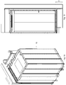
- FIGS 1A and 1B show respectively a schematic view and a side view of a known elevator car 1.
- a reinforcement with height 2 for the purpose of strengthening the car such that it can bear a determined load. Because this height 2 is considerable, it has to be taken into account during placing of the elevator or during construction of the building in which the elevator is placed.
- an elevator pit Provided for this purpose on the underside of the elevator shaft in which the elevator is mounted is an elevator pit. It is however not always possible or desirable to make such a pit.
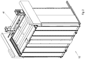
- FIG 2 shows an embodiment of an elevator car 10 according to the present invention. It will be immediately apparent from this figure that the underside of car 10 does not protrude as far downward as car 1 of figure 1A . This is possible because of the specific frame construction according to the invention, embodiments of which are shown in figures 3A and 3B .
- Figure 3A shows a frame 20 comprising a pair of uprights 21, 22 and a pair of supports 23, 24 which are attached to uprights 21, 22.
- Uprights 21, 22 are mutually connected here by transverse connections 25, 26.
- supports 23, 24 are embodied as a series of strips which are disposed adjacently of each other. A detail view of such a strip 27 is shown in figure 4 .
- FIG. 3A Also visible in figure 3A are further supports 28, 29. These supports 28, 29 are similar to supports 23, 24 in respect of construction and are thus also embodied as a series of strips.
- Each support 23, 24 comprises a first part, such as part 24A for support 24, a second part, such as part 24B for support 24, and a transition part, such as part 24C for support 24.
- Transition part 24C here forms a transition between parts 24A and 24B.
- the different parts of supports 23, 24 are integrally connected to each other and are preferably manufactured integrally from a type of steel with sufficient hardness. An example of such a steel is known under material number 1.8974.
- the angle between the first part and the second part of support 23, 24 and the angle between the third part and the fourth part of further support 28, 29 are preferably such that, following assembly of an empty car, the bottom part lies perpendicularly of uprights 21, 22.
- Each of the strips 27 comprises a plurality of openings 30, see figure 3A . Inserted through these openings are bolts with which supports 23, 24 are connected to uprights 21, 22. Because an elevator car is usually constructed at the location where the car will actually be used, the plurality of strips provides advantages compared to a single integral component. This is because the weight of such a component would complicate the assembly considerably. The use of strips further provides the option of adjusting the carrying capacity of the car to the conditions. The carrying capacity of the car can after all be increased by placing more strips.
- connection between strips 27 and the associated upright 21, 22 thus takes place using a plurality of bolts. Because the first part of supports 23, 24 extends over a considerable length along the associated upright 21, 22, it is possible to work with a relatively large contact surface between support 23, 24 and upright 21, 22. This increases the strength of the connection between support 23, 24 and upright 21, 22.
- Further supports 28, 29 can be coupled to supports 23, 24 by means of tensioning elements such as a tensioning cable, pull rod or tensioning beam (not shown). This achieves that a load exerted on the bottom of car 20 is distributed over supports 23, 24 and further supports 28, 29.
- tensioning elements such as a tensioning cable, pull rod or tensioning beam (not shown).
- FIG. 3B Shown here is another embodiment of a frame 200 in which other further supports 31, 32 which do not consist of a plurality of strips are used on the upper side. Whether further supports 28, 29 have to be used depends on the expected loading of the elevator car.
- uprights 21, 22 take a hollow form in order to limit the weight of uprights 21, 22.
- Uprights 21, 22 can be embodied here as partially open tubular structures, for instance with a U-shaped cross-section, as shown in figures 3A and 3B .
- each of the uprights 21, 22 comprises three walls.
- the wall directed toward bottom part 33 does not run as far downward here as the other walls.
- the hereby created recess is utilized by the transition part of the associated support 23, 24.
- the height of the transition part and the recess can be chosen here such that a substantially flat underside of the car can be realized.
- Per se known elements of an elevator car such as wall elements and automatic sliding doors, can be mounted on frame 20, 200.
- FIG. 5A shows a bottom part 33 which can be coupled to frame 20 or frame 200.
- Bottom part 33 comprises for this purpose two openings in the form of channels 34, 35.
- Received in bottom part 33 are a number of bolts 36 which can be used to clamp supports 23, 24 in bottom part 33. It is relatively easy to adjust bottom part 33 using this construction.
- strips 27 likewise comprise openings at the position of bottom part 33. Bolts with which supports 23, 24 are attached to bottom part 33 can be placed through these openings.
- Figure 5B shows a front side of the car. It will be apparent here that supports 23, 24 protrude slightly from channels 34, 35.
- Figure 6 shows a side view of the coupling between support 23, upright 21 and bottom part 33 as according to the embodiment of figure 3A . Visible in this figure are bolts 37 with which support 23 is attached to upright 21. A strengthening plate 38 is used here. Further shown are guides 39, 40 which guide the elevator car in the elevator shaft. The manner in which the elevator car is guided in the elevator shaft is realized here in known manner.
- Ceiling part 41 of the elevator car see figure 2
Landscapes
- Engineering & Computer Science (AREA)
- Civil Engineering (AREA)
- Mechanical Engineering (AREA)
- Structural Engineering (AREA)
- Cage And Drive Apparatuses For Elevators (AREA)
- Types And Forms Of Lifts (AREA)
- Vehicle Step Arrangements And Article Storage (AREA)
Description
- The present invention relates to a frame for a car of a passenger/freight elevator. The invention further relates to a car provided with such a frame. Finally, the invention also relates to an elevator comprising such a car.
- Passenger/freight elevators, known for instance from
JP 5 132269 A WO 2009/023387 A1 , are characterized in that they have a relatively high load capacity per surface area. It is hereby necessary that the elevator car, and particularly the frame thereof, be sufficiently strong to be able to bear the forces occurring during use. The known passenger/freight elevator comprises for this purpose on the underside of the elevator car a reinforcement in the form of transverse beams. Because these transverse beams protrude considerably in downward direction, an elevator pit has to be arranged during construction of the elevator installation. Such a pit makes it possible for the elevator car to be positioned in the lowest position such that the floor of the elevator car lies in line with a storey floor. - A drawback of the known elevator car is that it is not possible to arrange an elevator pit in every building or structure. A further drawback is that, when new buildings are being designed, the elevator pit is seen as undesirable design requirement at least partly determining, among others, the floor construction of a lowest storey for the elevator.
- An object of the present invention is to provide a frame or elevator car, wherein the above stated drawbacks do not occur, or hardly so.
- According to a first aspect of the present invention, this object is achieved with a frame for a car of a passenger/freight elevator comprising a pair of uprights disposed parallel to each other and extending in a transport direction of the passenger/freight elevator. Each upright is coupled here to a support. Each support has a first part and a second part integrally connected thereto. These parts lie at an angle relative to each other. The first part further runs parallel to the upright and is coupled to the upright in a direction transversely of the transport direction. The second parts of the supports extend in a plane for the purpose of supporting a bottom part of the passenger/freight elevator.
- The angle between the first part and the second part of the support is preferably such that, after assembly of an empty car, the second part bends relative to the first part so that the then resulting angle amounts to 90 degrees.
- According to the present invention a downward force on the bottom part of the passenger/freight elevator is absorbed by the supports and the uprights. Owing to the particular form of the supports, the load is transmitted via the second parts to the first parts integrally connected thereto. These are connected to the upright via a transverse connection. Use is preferably made here of a connection at multiple points, such as a welded connection or the use of a plurality of bolts. Because the first part extends in the transport direction, parallel to the upright, it is possible to realize the connecting points over a great distance between the upright and the support. The frame according to the invention can hereby cope with a greater load than a frame in which the bottom part is connected to the upright in a direction parallel to the bottom part. According to the invention, the uprights each take a substantially at least partially hollow form. The first part of each support can further be at least partially received here in the associated upright. Because the upright takes an at least partially, and preferably wholly hollow form, the total weight of the upright can remain limited without this detracting from the strength. Further according to the invention, the first part of the support is received in the upright, whereby a compact solution can be achieved.
- In a further embodiment each support comprises a transition part between, and integrally connected to, the first and second parts. Each upright can further be provided at an end directed toward the bottom part with a recess through which the transition part of the associated support protrudes. An advantageous construction can thus be achieved, wherein the whole first part of the support is received in the hollow upright and wherein the whole second part is located outside the upright. The transition part is preferably a curved element forming the transition between the substantially elongate first and second parts. The recess can be formed here in that one side of the hollow upright does not extend as far as the other sides. If the upright for instance take the form of a tubular element of U-shaped cross-section, a wall of the upright directed toward the bottom part can extend less far downward than the other walls. The space hereby created can be used by the transition part. The height of the transition part at the position of this wall is preferably such here that the underside of the transition part lies substantially in line with an underside of the other walls of the upright.
- In a further embodiment the recess and the transition part are formed such that an underside of each upright lies in line with an underside of the second part of the associated support. The underside of the frame, or the car comprising this frame, is hereby substantially flat and does not protrude on the underside, or hardly so, whereby the space required under the car is limited to a minimum.
- In an embodiment each support comprises a plurality of substantially identical strips, wherein the plurality of strips are placed adjacently of each other in a direction transversely of the transport direction for the purpose of forming the support. In this embodiment the support is not therefore manufactured as one integral part but is realized on site by mutually adjacent placing of substantially identical strips.
- The use of strips provides a number of advantages. A first advantage is that the carrying capacity of the car can be increased in relatively simple manner by using more strips. Another advantage is that it is relatively easy to construct the elevator car on site. This is because the individual strips are easier to handle and assemble than a support consisting of one piece. In addition, the use of strips is more attractive in terms of cost because a wide variety of cars of different loading capacities can be realized using a series of substantially identical components.
- In a further embodiment the strips are connected to each other and to the upright by a non-releasable connection such as a welded connection. In a recommended embodiment the strips are however connected to each other and to the upright by a releasable connection. An example of such a releasable connection is an embodiment wherein a part of each of the strips which corresponds to the first part of the support and the associated upright comprise corresponding openings through which a coupling means, such as a bolt, is placed for the purpose of coupling the strips to each other and to the upright. The bolt can be secured here in per se known manner, such as with a nut.
- In an embodiment the frame is provided at an end remote from the bottom part with a first transverse connection between the pair of uprights and/or the frame is provided at an end directed toward the bottom part with a second transverse connection between the pair of uprights. The above stated transverse connections strengthen the construction of the car in the transverse direction and also provide for and/or support the parallel disposition of the uprights.
- In an embodiment each upright is coupled to a further support, wherein each further support comprises a third part and a fourth part integrally connected thereto, which parts lie at an angle relative to each other, wherein the third part runs parallel to the upright and is coupled to the upright in a direction transversely of the transport direction, and wherein the fourth parts of the further supports extend in a plane for the purpose of supporting a ceiling part of the passenger/freight elevator. In this embodiment supports are thus also used on the upper side in addition to the supports on the underside of the frame or the car. The advantages of the further supports are similar to those of the supports on the underside. These supports can however absorb forces which are exerted on the ceiling part. These forces may be direct, for instance in that the ceiling part itself has to bear a weight, or indirect, in that a load is transmitted from the car to the ceiling part.
- The angle between the third part and the fourth part of the further support is preferably such that, following assembly of an empty car, the fourth part bends relative to the third part so that the then resulting angle amounts to 90 degrees.
- In a further embodiment, wherein the uprights take an at least partially hollow form, each further support comprises a further transition part between, and integrally connected to, the third and fourth part, and each upright is provided at an end directed toward the ceiling part with a further recess through which the further transition part of the associated further support protrudes. The further recess and the further transition part are formed here such that an upper side of each upright lies in line with an upper side of the third part of the support. In this embodiment a substantially symmetrical construction is obtained in respect of uprights, supports and further supports. It is advantageous here for the further support and/or upright to be embodied as the above stated support and/or upright. The use of a plurality of strips is once again an advantageous embodiment here for the further support.
- The further support and the support can be mutually coupled for the purpose of distributing the load exerted on the bottom part. This is for instance possible by making use of a tensioning connection per upright between the second part of the associated support and the fourth part of the associated further support. An example of such a tensioning connection is a pull rod.
- According to a second aspect, the present invention provides a car of a passenger/freight elevator comprising the above described frame.
- In an embodiment the car further comprises a bottom part provided with an opening in which the second part of a support is at least partially received. It is recommended here to provide an opening for each support. These openings can for instance be formed as a channel connecting to the second part of the support. This channel preferably extends over the whole bottom part and over substantially the whole length of the second part of the support.
- In order to connect the second part to the bottom part it is advantageous for the second part of a support and the bottom part to comprise corresponding coupling openings through which a coupling means, such as a bolt, is placed for the purpose of coupling the support to the bottom part. In another embodiment the bottom part is however provided with clamping elements for clamping the second part of a support in the bottom part. These clamping elements can for instance be embodied as bolts.
- In an embodiment of the car the support is formed by a plurality of strips as described above. In this embodiment however, a part of each of the strips which corresponds to the second part of the support and the bottom part comprise corresponding openings through which a coupling means, such as a bolt, is placed for the purpose of coupling the strips to each other and to the bottom part.
- In an embodiment the car comprises further supports as described above, as well as a ceiling part. The ceiling part is provided here with an opening in which the fourth part of the further support is at least partially received. This opening is preferably formed as a channel connecting to the fourth part of the further support.
- In a further embodiment the fourth part of the further support and the ceiling part comprise corresponding coupling openings through which a coupling means, such as a bolt, is placed for the purpose of coupling the further support to the ceiling part. In another embodiment the ceiling part is however provided with clamping elements for clamping the fourth part of a further support in the ceiling part. These clamping elements can for instance be embodied as bolts.
- According to a third aspect, the invention provides a passenger/freight elevator comprising the above described car.
- The invention will be discussed in more detail hereinbelow, wherein:
-
Figures 1A and 1B show respectively a schematic view and a side view of a known elevator car; -
Figure 2 shows an embodiment of an elevator car according to the present invention; -
Figures 3A and 3B show two embodiments of a frame for an elevator car according to the present invention; -
Figure 4 shows an embodiment of a strip for the purpose of forming a support offigure 3A ; -
Figure 5A shows the bottom part of the car offigure 2 andfigure 5B shows a front side of the car offigure 2 ; and -
Figure 6 shows a side view of the coupling between support, upright and bottom part as according to the embodiment offigure 3A . -
Figures 1A and 1B show respectively a schematic view and a side view of a known elevator car 1. It will be apparent here that arranged on the underside is a reinforcement withheight 2 for the purpose of strengthening the car such that it can bear a determined load. Because thisheight 2 is considerable, it has to be taken into account during placing of the elevator or during construction of the building in which the elevator is placed. Provided for this purpose on the underside of the elevator shaft in which the elevator is mounted is an elevator pit. It is however not always possible or desirable to make such a pit. -
Figure 2 shows an embodiment of anelevator car 10 according to the present invention. It will be immediately apparent from this figure that the underside ofcar 10 does not protrude as far downward as car 1 offigure 1A . This is possible because of the specific frame construction according to the invention, embodiments of which are shown infigures 3A and 3B . -
Figure 3A shows aframe 20 comprising a pair ofuprights supports uprights Uprights transverse connections strip 27 is shown infigure 4 . - Also visible in
figure 3A arefurther supports supports - Each
support support 24, a second part, such aspart 24B forsupport 24, and a transition part, such aspart 24C forsupport 24.Transition part 24C here forms a transition betweenparts 24A and 24B. The different parts ofsupports - The angle between the first part and the second part of
support further support uprights - Each of the
strips 27 comprises a plurality ofopenings 30, seefigure 3A . Inserted through these openings are bolts with which supports 23, 24 are connected touprights - The connection between
strips 27 and the associatedupright supports upright support upright support upright - Further supports 28, 29 can be coupled to
supports car 20 is distributed oversupports - The use of such supports is however not essential, as shown in
figure 3B . Shown here is another embodiment of aframe 200 in which other further supports 31, 32 which do not consist of a plurality of strips are used on the upper side. Whether further supports 28, 29 have to be used depends on the expected loading of the elevator car. - It will be apparent from
figures 3A and 3B that uprights 21, 22 take a hollow form in order to limit the weight ofuprights Uprights figures 3A and 3B . - In
figures 3A and 3B each of theuprights bottom part 33 does not run as far downward here as the other walls. The hereby created recess is utilized by the transition part of the associatedsupport figure 6 , the height of the transition part and the recess can be chosen here such that a substantially flat underside of the car can be realized. - Per se known elements of an elevator car, such as wall elements and automatic sliding doors, can be mounted on
frame -
Figure 5A shows abottom part 33 which can be coupled to frame 20 orframe 200.Bottom part 33 comprises for this purpose two openings in the form ofchannels bottom part 33 are a number ofbolts 36 which can be used to clampsupports bottom part 33. It is relatively easy to adjustbottom part 33 using this construction. In another embodiment strips 27 likewise comprise openings at the position ofbottom part 33. Bolts with which supports 23, 24 are attached tobottom part 33 can be placed through these openings. -
Figure 5B shows a front side of the car. It will be apparent here that supports 23, 24 protrude slightly fromchannels -
Figure 6 shows a side view of the coupling betweensupport 23,upright 21 andbottom part 33 as according to the embodiment offigure 3A . Visible in this figure arebolts 37 with which support 23 is attached toupright 21. A strengtheningplate 38 is used here. Further shown areguides -
Ceiling part 41 of the elevator car, seefigure 2 , can likewise be provided with channels in similar manner tobottom part 33. This makes it possible to attachfurther supports frame 20 toceiling part 41 in simple manner. - The invention is described in the foregoing inter alia on the basis of embodiments thereof. It will be apparent to the skilled person that various changes to these embodiments are possible without departing from the scope of protection of the present invention as defined by the appended claims.
Claims (13)
- A frame (20, 200) for a car of a passenger/freight elevator, comprising a pair of uprights (21, 22) disposed parallel to each other and extending in a transport direction of the passenger/freight elevator, wherein each upright (21, 22) is coupled to a support (23, 24), wherein each support (23, 24) comprises a first part (24A) and a second part (24B) integrally connected thereto, which parts lie at an angle relative to each other, wherein the first part runs parallel to the upright and is coupled to the upright in a direction transversely of the transport direction and wherein the second parts of the supports extend in a plane for the purpose of supporting a bottom part (33) of the passenger/freight elevator;
wherein the uprights (21, 22) each take a substantially at least partially hollow form
characterised in that the first part of each support is at least partially received in the associated upright. - The frame (20, 200) as claimed in claim 1, wherein each support comprises a transition part (24C) between, and integrally connected to, the first and second parts, and wherein each upright (21, 22) is provided at an end directed toward the bottom part with a recess through which the transition part of the associated support (23, 24) protrudes.
- The frame (20, 200) as claimed in claim 2, wherein the recess and the transition part are formed such that an underside of each upright (21, 22) lies in line with an underside of the second part of the associated support (23, 24).
- The frame (20, 200) as claimed in any of the foregoing claims, wherein each support (23, 24) comprises a plurality of substantially identical strips (27), wherein the plurality of strips are placed adjacently of each other in a direction transversely of the transport direction for the purpose of forming the support (23, 24);
wherein the strips (27) are connected to each other and to the upright (21, 22) preferably by a non-releasable connection such as a welded connection or by a releasable connection, wherein a part of each of the strips (27) which corresponds to the first part (24A) of the support (23, 24) and the associated upright (21, 22) preferably comprise corresponding openings (30) through which a coupling means, such as a bolt, is placed for the purpose of releasably coupling the strips (27) to each other and to the upright (21, 22). - The frame (20, 200) as claimed in any of the foregoing claims, wherein the frame (20, 200) is provided at an end remote from the bottom part (33) with a first transverse connection between the pair of uprights (21, 22) and/or wherein the frame (20, 200) is provided at an end directed toward the bottom part (33) with a second transverse connection between the pair of uprights (21, 22).
- The frame (20, 200) as claimed in any of the foregoing claims, wherein each upright (21, 22) is coupled to a further support (28, 29), wherein each further support (28, 29) comprises a third part and a fourth part integrally connected thereto, which parts lie at an angle relative to each other, wherein the third part runs parallel to the upright (21, 22) and is coupled to the upright (21, 22) in a direction transversely of the transport direction, and wherein the fourth parts of the further supports (28, 29) extend in a plane for the purpose of supporting a ceiling part (41) of the passenger/freight elevator.
- The frame (20, 200) as claimed in claim 6, wherein each further support (28, 29) comprises a further transition part between, and integrally connected to, the third and fourth part, and wherein each upright (21, 22) is provided at an end directed toward the ceiling part (41) with a further recess through which the further transition part of the associated further support (28, 29) protrudes;
wherein the further recess and the further transition part are preferably formed such that an upper side of each upright (21, 22) lies in line with an upper side of the third part of the support; and/or
wherein each further support (28, 29) comprises a plurality of substantially identical strips (27), wherein the plurality of strips are placed adjacently of each other in a direction transversely of the transport direction for the purpose of forming the further support, wherein the strips (27) are connected to each other and to the upright preferably by a non-releasable connection such as a welded connection or by a releasable connection, wherein a part of each of the strips (27) which corresponds to the third part of the further support (28, 29) and the associated upright (21, 22) preferably comprise corresponding openings through which a coupling means, such as a bolt, is placed for the purpose of releasably coupling the strips (27) to each other and to the upright (21, 22);
the frame (20, 200) preferably further comprising a tensioning connection per upright (21, 22) between the second part (24B) of the associated support (23, 24) and the fourth part of the associated further support (28, 29). - A car of a passenger/freight elevator, comprising the frame (20, 200) as claimed in any of the foregoing claims;
the car preferably further comprising a bottom part (33) provided with an opening (30) in which the second part (24B) of a support (23, 24) is at least partially received;
wherein the opening in the bottom part (33) is preferably formed as a channel (34, 35) connecting to the second part of the support;
wherein the second part (24B) of a support (23, 24) and the bottom part (33) preferably comprise corresponding coupling openings through which a coupling means, such as a bolt, is placed for the purpose of coupling the support to the bottom part or wherein the bottom part preferably comprises clamping elements for clamping the second part of a support in the bottom part. - The car as claimed in claim 8, to the extent that the second part (24B) of a support (23, 24) and the bottom part (33) preferably comprise corresponding coupling openings through which a coupling means, such as a bolt, is placed for the purpose of coupling the support to the bottom part, wherein each support (23, 24) comprises a plurality of substantially identical strips (27), wherein the plurality of strips (27) are placed adjacently of each other in a direction transversely of the transport direction for the purpose of forming the support (23, 24), wherein the strips (27) are preferably connected to each other and to the upright (21, 22) by a releasable connection, wherein a part of each of the strips (27) which corresponds to the first part (24A) of the support (23, 24) and the associated upright (21, 22) preferably comprise corresponding openings (30) through which a coupling means, such as a bolt, is placed for the purpose of releasably coupling the strips (27) to each other and to the upright (21, 22), wherein a part of each of the strips (27) which corresponds to the second part (24B) of the support (23, 24) and the bottom part (33) comprise corresponding openings through which a coupling means, such as a bolt, is placed for the purpose of coupling the strips to each other and to the bottom part.
- The car as claimed in any of the claims 8-9, wherein each upright (21, 22) is coupled to a further support (28, 29), wherein each further support (28, 29) comprises a further transition part between, and integrally connected to, the third and fourth part, and wherein each upright (21, 22) is provided at an end directed toward the ceiling part (41) with a further recess through which the further transition part of the associated further support protrudes;
wherein the further recess and the further transition part are preferably formed such that an upper side of each upright (21, 22) lies in line with an upper side of the third part of the support; and/or
wherein each further support (28, 29) preferably comprises a plurality of substantially identical strips (27), wherein the plurality of strips (27) are placed adjacently of each other in a direction transversely of the transport direction for the purpose of forming the further support (28, 29), wherein the strips (27) are connected to each other and to the upright (21, 22) preferably by a non-releasable connection such as a welded connection or by a releasable connection, wherein a part of each of the strips (27) which corresponds to the third part of the further support (28, 29) and the associated upright (21, 22) preferably comprise corresponding openings through which a coupling means, such as a bolt, is placed for the purpose of releasably coupling the strips (27) to each other and to the upright;
the frame (20, 200) preferably further comprising a tensioning connection per upright (21, 22) between the second part (24B) of the associated support (23, 24) and the fourth part of the associated further support (28, 29), the car further comprising a ceiling part (41) provided with an opening in which the fourth part of the further support (28, 29) is at least partially received. - The car as claimed in claim 10, wherein the opening in the ceiling part (41) is formed as a channel connecting to the fourth part of the further support (28, 29).
- The car as claimed in claim 10 or 11, wherein the fourth part of the further support (28, 29) and the ceiling part (41) comprise corresponding coupling openings through which a coupling means, such as a bolt, is placed for the purpose of coupling the further support (28, 29) to the ceiling part (41) or wherein the ceiling part (41) comprises clamping elements for clamping the fourth part of a further support in the ceiling part.
- A passenger/freight elevator comprising the car as claimed in any of the claims 8-12.
Priority Applications (5)
| Application Number | Priority Date | Filing Date | Title |
|---|---|---|---|
| SM20180414T SMT201800414T1 (en) | 2011-12-13 | 2012-12-12 | Frame for a car of a passenger/freight elevator, and such a car and passenger/freight elevator |
| RS20180872A RS57478B1 (en) | 2011-12-13 | 2012-12-12 | Frame for a car of a passenger/freight elevator, and such a car and passenger/freight elevator |
| PL12820965T PL2791042T3 (en) | 2011-12-13 | 2012-12-12 | Frame for a car of a passenger/freight elevator, and such a car and passenger/freight elevator |
| SI201231345T SI2791042T1 (en) | 2011-12-13 | 2012-12-12 | Frame for a car of a passenger/freight elevator, and such a car and passenger/freight elevator |
| HRP20181191TT HRP20181191T1 (en) | 2011-12-13 | 2012-12-12 | Frame for a car of a passenger/freight elevator, and such a car and passenger/freight elevator |
Applications Claiming Priority (2)
| Application Number | Priority Date | Filing Date | Title |
|---|---|---|---|
| NL2007961A NL2007961C2 (en) | 2011-12-13 | 2011-12-13 | SET FOR A CABIN OF A PERSONAL GOOD LIFT, SUCH A CABIN AND PERSONAL GOOD LIFT. |
| PCT/NL2012/050881 WO2013095113A2 (en) | 2011-12-13 | 2012-12-12 | Frame for a car of a passenger/freight elevator, and such a car and passenger/freight elevator |
Publications (2)
| Publication Number | Publication Date |
|---|---|
| EP2791042A2 EP2791042A2 (en) | 2014-10-22 |
| EP2791042B1 true EP2791042B1 (en) | 2018-04-25 |
Family
ID=47630480
Family Applications (1)
| Application Number | Title | Priority Date | Filing Date |
|---|---|---|---|
| EP12820965.7A Active EP2791042B1 (en) | 2011-12-13 | 2012-12-12 | Frame for a car of a passenger/freight elevator, and such a car and passenger/freight elevator |
Country Status (18)
| Country | Link |
|---|---|
| US (1) | US9828217B2 (en) |
| EP (1) | EP2791042B1 (en) |
| AU (1) | AU2012354320B2 (en) |
| CA (1) | CA2859160A1 (en) |
| CY (1) | CY1120476T1 (en) |
| DK (1) | DK2791042T3 (en) |
| EA (1) | EA027653B1 (en) |
| ES (1) | ES2680916T3 (en) |
| HR (1) | HRP20181191T1 (en) |
| HU (1) | HUE038530T2 (en) |
| LT (1) | LT2791042T (en) |
| NL (1) | NL2007961C2 (en) |
| PL (1) | PL2791042T3 (en) |
| PT (1) | PT2791042T (en) |
| RS (1) | RS57478B1 (en) |
| SI (1) | SI2791042T1 (en) |
| SM (1) | SMT201800414T1 (en) |
| WO (1) | WO2013095113A2 (en) |
Families Citing this family (4)
| Publication number | Priority date | Publication date | Assignee | Title |
|---|---|---|---|---|
| EP3560877A1 (en) * | 2018-04-27 | 2019-10-30 | Otis Elevator Company | Elevator car frame |
| CN110642124B (en) * | 2019-09-25 | 2021-07-02 | 苏州珀威智能科技有限公司 | Method for installing elevator frame |
| FR3103185B1 (en) * | 2019-11-20 | 2021-10-15 | I R E A | Space-saving elevator installation |
| CN116511813B (en) * | 2023-07-03 | 2023-09-22 | 山西建筑工程集团有限公司 | Integral tool for construction lifter cage combination |
Family Cites Families (6)
| Publication number | Priority date | Publication date | Assignee | Title |
|---|---|---|---|---|
| JPS5132269B1 (en) * | 1970-06-10 | 1976-09-11 | ||
| JPH05132269A (en) * | 1991-02-22 | 1993-05-28 | Mitsubishi Electric Corp | Cage device of elevator |
| ATE217855T1 (en) * | 1997-03-06 | 2002-06-15 | Inventio Ag | ELEVATOR CABIN |
| SG74736A1 (en) * | 1998-07-13 | 2000-08-22 | Inventio Ag | Car structure |
| JP5085325B2 (en) * | 2004-09-09 | 2012-11-28 | インベンテイオ・アクテイエンゲゼルシヤフト | Module elevator car |
| FI125070B (en) * | 2007-07-24 | 2015-05-29 | Kone Corp | Basket frame for an elevator and arrangement for fitting an elevator basket into a basket frame |
-
2011
- 2011-12-13 NL NL2007961A patent/NL2007961C2/en not_active IP Right Cessation
-
2012
- 2012-12-12 HR HRP20181191TT patent/HRP20181191T1/en unknown
- 2012-12-12 ES ES12820965.7T patent/ES2680916T3/en active Active
- 2012-12-12 HU HUE12820965A patent/HUE038530T2/en unknown
- 2012-12-12 AU AU2012354320A patent/AU2012354320B2/en not_active Ceased
- 2012-12-12 RS RS20180872A patent/RS57478B1/en unknown
- 2012-12-12 US US14/365,462 patent/US9828217B2/en not_active Expired - Fee Related
- 2012-12-12 DK DK12820965.7T patent/DK2791042T3/en active
- 2012-12-12 WO PCT/NL2012/050881 patent/WO2013095113A2/en not_active Ceased
- 2012-12-12 SI SI201231345T patent/SI2791042T1/en unknown
- 2012-12-12 SM SM20180414T patent/SMT201800414T1/en unknown
- 2012-12-12 EA EA201400681A patent/EA027653B1/en not_active IP Right Cessation
- 2012-12-12 EP EP12820965.7A patent/EP2791042B1/en active Active
- 2012-12-12 CA CA2859160A patent/CA2859160A1/en not_active Abandoned
- 2012-12-12 PT PT128209657T patent/PT2791042T/en unknown
- 2012-12-12 LT LTEP12820965.7T patent/LT2791042T/en unknown
- 2012-12-12 PL PL12820965T patent/PL2791042T3/en unknown
-
2018
- 2018-07-25 CY CY20181100778T patent/CY1120476T1/en unknown
Non-Patent Citations (1)
| Title |
|---|
| None * |
Also Published As
| Publication number | Publication date |
|---|---|
| EA201400681A1 (en) | 2014-11-28 |
| EA027653B1 (en) | 2017-08-31 |
| HRP20181191T1 (en) | 2018-10-05 |
| AU2012354320B2 (en) | 2017-05-25 |
| DK2791042T3 (en) | 2018-08-06 |
| SI2791042T1 (en) | 2018-12-31 |
| EP2791042A2 (en) | 2014-10-22 |
| WO2013095113A3 (en) | 2013-10-10 |
| LT2791042T (en) | 2018-09-10 |
| CY1120476T1 (en) | 2019-07-10 |
| SMT201800414T1 (en) | 2018-09-13 |
| AU2012354320A1 (en) | 2014-07-03 |
| US9828217B2 (en) | 2017-11-28 |
| PT2791042T (en) | 2018-07-27 |
| WO2013095113A2 (en) | 2013-06-27 |
| US20140374197A1 (en) | 2014-12-25 |
| CA2859160A1 (en) | 2013-06-27 |
| RS57478B1 (en) | 2018-10-31 |
| HUE038530T2 (en) | 2018-10-29 |
| ES2680916T3 (en) | 2018-09-11 |
| NL2007961C2 (en) | 2013-06-17 |
| PL2791042T3 (en) | 2018-10-31 |
Similar Documents
| Publication | Publication Date | Title |
|---|---|---|
| EP1970341B9 (en) | Self-supporting cabin | |
| AU740265B2 (en) | Elevator car | |
| US6991069B1 (en) | Cable elevator with a drive plate | |
| CA2681062C (en) | Hold down system using hollow bearing members | |
| US20040094371A1 (en) | Elevator counter weight | |
| US9828217B2 (en) | Frame for a car of a passenger/freight elevator, and such a car and passenger/freight elevator | |
| US7261184B2 (en) | Elevator system and triangulated support structure for the same | |
| KR102119926B1 (en) | Cable tray | |
| US7963410B2 (en) | Container floor plate, in particular for a refrigerated container | |
| EP3103753B1 (en) | Combined guide rail for an elevator system | |
| JP2008512324A (en) | Module elevator car | |
| CN101503889B (en) | T-shaped connection node of steel reinforced concrete full-prefabricated assembly structural beam | |
| US20110100943A1 (en) | Mast for a stacker crane | |
| KR101329372B1 (en) | Deflection control structure of deck plate of slim floor with demountable tendon and construction method thereof | |
| CN210001391U (en) | Vertical tractor base of elevator without machine room | |
| FI120413B (en) | Closed jetty | |
| CN210340014U (en) | Combined bearing beam for special construction elevator in hoistway | |
| KR20070088587A (en) | How to install the elevator car and elevator car | |
| CN215974499U (en) | Reinforced car bottom bracket | |
| CN101847449A (en) | Support the framework of shell | |
| CN211341682U (en) | Lower hoisting point truss for climbing frame | |
| CN108149994B (en) | A kind of light and handy vehicle-carrying plate | |
| CN120622270A (en) | Heavy goods lift with high bearing capacity | |
| JP5114588B2 (en) | Lining board | |
| HK1065772B (en) | Counterweight for elevator |
Legal Events
| Date | Code | Title | Description |
|---|---|---|---|
| PUAI | Public reference made under article 153(3) epc to a published international application that has entered the european phase |
Free format text: ORIGINAL CODE: 0009012 |
|
| 17P | Request for examination filed |
Effective date: 20140616 |
|
| AK | Designated contracting states |
Kind code of ref document: A2 Designated state(s): AL AT BE BG CH CY CZ DE DK EE ES FI FR GB GR HR HU IE IS IT LI LT LU LV MC MK MT NL NO PL PT RO RS SE SI SK SM TR |
|
| AX | Request for extension of the european patent |
Extension state: BA ME |
|
| 17Q | First examination report despatched |
Effective date: 20160113 |
|
| GRAP | Despatch of communication of intention to grant a patent |
Free format text: ORIGINAL CODE: EPIDOSNIGR1 |
|
| INTG | Intention to grant announced |
Effective date: 20171122 |
|
| GRAS | Grant fee paid |
Free format text: ORIGINAL CODE: EPIDOSNIGR3 |
|
| GRAA | (expected) grant |
Free format text: ORIGINAL CODE: 0009210 |
|
| AK | Designated contracting states |
Kind code of ref document: B1 Designated state(s): AL AT BE BG CH CY CZ DE DK EE ES FI FR GB GR HR HU IE IS IT LI LT LU LV MC MK MT NL NO PL PT RO RS SE SI SK SM TR |
|
| AX | Request for extension of the european patent |
Extension state: BA ME |
|
| REG | Reference to a national code |
Ref country code: GB Ref legal event code: FG4D |
|
| REG | Reference to a national code |
Ref country code: CH Ref legal event code: EP |
|
| REG | Reference to a national code |
Ref country code: AT Ref legal event code: REF Ref document number: 992648 Country of ref document: AT Kind code of ref document: T Effective date: 20180515 |
|
| REG | Reference to a national code |
Ref country code: IE Ref legal event code: FG4D |
|
| REG | Reference to a national code |
Ref country code: DE Ref legal event code: R096 Ref document number: 602012045720 Country of ref document: DE |
|
| REG | Reference to a national code |
Ref country code: HR Ref legal event code: TUEP Ref document number: P20181191 Country of ref document: HR Ref country code: RO Ref legal event code: EPE |
|
| REG | Reference to a national code |
Ref country code: PT Ref legal event code: SC4A Ref document number: 2791042 Country of ref document: PT Date of ref document: 20180727 Kind code of ref document: T Free format text: AVAILABILITY OF NATIONAL TRANSLATION Effective date: 20180723 |
|
| REG | Reference to a national code |
Ref country code: CH Ref legal event code: NV Representative=s name: ARNOLD AND SIEDSMA AG, CH |
|
| REG | Reference to a national code |
Ref country code: DK Ref legal event code: T3 Effective date: 20180730 |
|
| REG | Reference to a national code |
Ref country code: NL Ref legal event code: FP |
|
| REG | Reference to a national code |
Ref country code: SE Ref legal event code: TRGR |
|
| REG | Reference to a national code |
Ref country code: ES Ref legal event code: FG2A Ref document number: 2680916 Country of ref document: ES Kind code of ref document: T3 Effective date: 20180911 |
|
| REG | Reference to a national code |
Ref country code: EE Ref legal event code: FG4A Ref document number: 015794 Country of ref document: EE Effective date: 20180723 |
|
| REG | Reference to a national code |
Ref country code: NO Ref legal event code: T2 Effective date: 20180425 |
|
| REG | Reference to a national code |
Ref country code: HR Ref legal event code: T1PR Ref document number: P20181191 Country of ref document: HR |
|
| REG | Reference to a national code |
Ref country code: HU Ref legal event code: AG4A Ref document number: E038530 Country of ref document: HU |
|
| REG | Reference to a national code |
Ref country code: SK Ref legal event code: T3 Ref document number: E 27884 Country of ref document: SK |
|
| REG | Reference to a national code |
Ref country code: HR Ref legal event code: ODRP Ref document number: P20181191 Country of ref document: HR Payment date: 20181121 Year of fee payment: 7 |
|
| REG | Reference to a national code |
Ref country code: GR Ref legal event code: EP Ref document number: 20180402099 Country of ref document: GR Effective date: 20190109 |
|
| REG | Reference to a national code |
Ref country code: DE Ref legal event code: R097 Ref document number: 602012045720 Country of ref document: DE |
|
| PLBE | No opposition filed within time limit |
Free format text: ORIGINAL CODE: 0009261 |
|
| STAA | Information on the status of an ep patent application or granted ep patent |
Free format text: STATUS: NO OPPOSITION FILED WITHIN TIME LIMIT |
|
| 26N | No opposition filed |
Effective date: 20190128 |
|
| PG25 | Lapsed in a contracting state [announced via postgrant information from national office to epo] |
Ref country code: AL Free format text: LAPSE BECAUSE OF FAILURE TO SUBMIT A TRANSLATION OF THE DESCRIPTION OR TO PAY THE FEE WITHIN THE PRESCRIBED TIME-LIMIT Effective date: 20180425 |
|
| REG | Reference to a national code |
Ref country code: HR Ref legal event code: ODRP Ref document number: P20181191 Country of ref document: HR Payment date: 20191121 Year of fee payment: 8 |
|
| PGFP | Annual fee paid to national office [announced via postgrant information from national office to epo] |
Ref country code: RO Payment date: 20191121 Year of fee payment: 8 Ref country code: CY Payment date: 20191127 Year of fee payment: 8 Ref country code: CZ Payment date: 20191129 Year of fee payment: 8 Ref country code: SK Payment date: 20191120 Year of fee payment: 8 Ref country code: BG Payment date: 20191218 Year of fee payment: 8 Ref country code: SE Payment date: 20191227 Year of fee payment: 8 Ref country code: FI Payment date: 20191227 Year of fee payment: 8 Ref country code: LT Payment date: 20191119 Year of fee payment: 8 Ref country code: IE Payment date: 20191227 Year of fee payment: 8 Ref country code: MC Payment date: 20191121 Year of fee payment: 8 Ref country code: HU Payment date: 20191203 Year of fee payment: 8 |
|
| PGFP | Annual fee paid to national office [announced via postgrant information from national office to epo] |
Ref country code: SI Payment date: 20191120 Year of fee payment: 8 Ref country code: LV Payment date: 20191219 Year of fee payment: 8 Ref country code: EE Payment date: 20191219 Year of fee payment: 8 Ref country code: IS Payment date: 20191218 Year of fee payment: 8 Ref country code: PL Payment date: 20191120 Year of fee payment: 8 Ref country code: HR Payment date: 20191121 Year of fee payment: 8 Ref country code: SM Payment date: 20191223 Year of fee payment: 8 Ref country code: RS Payment date: 20191122 Year of fee payment: 8 Ref country code: LU Payment date: 20191227 Year of fee payment: 8 Ref country code: GR Payment date: 20191230 Year of fee payment: 8 |
|
| PGFP | Annual fee paid to national office [announced via postgrant information from national office to epo] |
Ref country code: AT Payment date: 20191219 Year of fee payment: 8 Ref country code: MT Payment date: 20191218 Year of fee payment: 8 Ref country code: MK Payment date: 20191121 Year of fee payment: 8 Ref country code: TR Payment date: 20191128 Year of fee payment: 8 |
|
| PGFP | Annual fee paid to national office [announced via postgrant information from national office to epo] |
Ref country code: NO Payment date: 20191227 Year of fee payment: 8 Ref country code: GB Payment date: 20200102 Year of fee payment: 8 Ref country code: DK Payment date: 20191230 Year of fee payment: 8 |
|
| REG | Reference to a national code |
Ref country code: AT Ref legal event code: UEP Ref document number: 992648 Country of ref document: AT Kind code of ref document: T Effective date: 20180425 |
|
| PGFP | Annual fee paid to national office [announced via postgrant information from national office to epo] |
Ref country code: PT Payment date: 20201221 Year of fee payment: 9 |
|
| REG | Reference to a national code |
Ref country code: HR Ref legal event code: PBON Ref document number: P20181191 Country of ref document: HR Effective date: 20201212 |
|
| REG | Reference to a national code |
Ref country code: FI Ref legal event code: MAE |
|
| REG | Reference to a national code |
Ref country code: DK Ref legal event code: EBP Effective date: 20201231 |
|
| REG | Reference to a national code |
Ref country code: NO Ref legal event code: MMEP |
|
| PG25 | Lapsed in a contracting state [announced via postgrant information from national office to epo] |
Ref country code: FI Free format text: LAPSE BECAUSE OF NON-PAYMENT OF DUE FEES Effective date: 20201212 Ref country code: RO Free format text: LAPSE BECAUSE OF NON-PAYMENT OF DUE FEES Effective date: 20201212 Ref country code: CY Free format text: LAPSE BECAUSE OF NON-PAYMENT OF DUE FEES Effective date: 20201212 Ref country code: CZ Free format text: LAPSE BECAUSE OF NON-PAYMENT OF DUE FEES Effective date: 20201212 |
|
| REG | Reference to a national code |
Ref country code: SE Ref legal event code: EUG |
|
| REG | Reference to a national code |
Ref country code: AT Ref legal event code: MM01 Ref document number: 992648 Country of ref document: AT Kind code of ref document: T Effective date: 20201212 |
|
| GBPC | Gb: european patent ceased through non-payment of renewal fee |
Effective date: 20201212 |
|
| REG | Reference to a national code |
Ref country code: SK Ref legal event code: MM4A Ref document number: E 27884 Country of ref document: SK Effective date: 20201212 |
|
| PG25 | Lapsed in a contracting state [announced via postgrant information from national office to epo] |
Ref country code: MC Free format text: LAPSE BECAUSE OF NON-PAYMENT OF DUE FEES Effective date: 20210104 Ref country code: LV Free format text: LAPSE BECAUSE OF NON-PAYMENT OF DUE FEES Effective date: 20201212 |
|
| PG25 | Lapsed in a contracting state [announced via postgrant information from national office to epo] |
Ref country code: RS Free format text: LAPSE BECAUSE OF NON-PAYMENT OF DUE FEES Effective date: 20201212 |
|
| REG | Reference to a national code |
Ref country code: LT Ref legal event code: MM4D Effective date: 20201212 |
|
| PG25 | Lapsed in a contracting state [announced via postgrant information from national office to epo] |
Ref country code: EE Free format text: LAPSE BECAUSE OF NON-PAYMENT OF DUE FEES Effective date: 20201231 Ref country code: LU Free format text: LAPSE BECAUSE OF NON-PAYMENT OF DUE FEES Effective date: 20201212 Ref country code: SM Free format text: LAPSE BECAUSE OF NON-PAYMENT OF DUE FEES Effective date: 20210707 Ref country code: AT Free format text: LAPSE BECAUSE OF NON-PAYMENT OF DUE FEES Effective date: 20201212 Ref country code: BG Free format text: LAPSE BECAUSE OF NON-PAYMENT OF DUE FEES Effective date: 20210630 Ref country code: HR Free format text: LAPSE BECAUSE OF NON-PAYMENT OF DUE FEES Effective date: 20201212 Ref country code: HU Free format text: LAPSE BECAUSE OF NON-PAYMENT OF DUE FEES Effective date: 20201213 Ref country code: IE Free format text: LAPSE BECAUSE OF NON-PAYMENT OF DUE FEES Effective date: 20201212 |
|
| PG25 | Lapsed in a contracting state [announced via postgrant information from national office to epo] |
Ref country code: SK Free format text: LAPSE BECAUSE OF NON-PAYMENT OF DUE FEES Effective date: 20201212 Ref country code: NO Free format text: LAPSE BECAUSE OF NON-PAYMENT OF DUE FEES Effective date: 20201231 Ref country code: GB Free format text: LAPSE BECAUSE OF NON-PAYMENT OF DUE FEES Effective date: 20201212 Ref country code: SE Free format text: LAPSE BECAUSE OF NON-PAYMENT OF DUE FEES Effective date: 20201213 Ref country code: GR Free format text: LAPSE BECAUSE OF NON-PAYMENT OF DUE FEES Effective date: 20210707 |
|
| REG | Reference to a national code |
Ref country code: SI Ref legal event code: KO00 Effective date: 20211126 |
|
| PG25 | Lapsed in a contracting state [announced via postgrant information from national office to epo] |
Ref country code: LT Free format text: LAPSE BECAUSE OF NON-PAYMENT OF DUE FEES Effective date: 20201212 Ref country code: DK Free format text: LAPSE BECAUSE OF NON-PAYMENT OF DUE FEES Effective date: 20201231 |
|
| PG25 | Lapsed in a contracting state [announced via postgrant information from national office to epo] |
Ref country code: SI Free format text: LAPSE BECAUSE OF NON-PAYMENT OF DUE FEES Effective date: 20201213 |
|
| PG25 | Lapsed in a contracting state [announced via postgrant information from national office to epo] |
Ref country code: TR Free format text: LAPSE BECAUSE OF NON-PAYMENT OF DUE FEES Effective date: 20201212 Ref country code: MT Free format text: LAPSE BECAUSE OF NON-PAYMENT OF DUE FEES Effective date: 20201212 |
|
| PG25 | Lapsed in a contracting state [announced via postgrant information from national office to epo] |
Ref country code: PT Free format text: LAPSE BECAUSE OF NON-PAYMENT OF DUE FEES Effective date: 20220613 |
|
| PG25 | Lapsed in a contracting state [announced via postgrant information from national office to epo] |
Ref country code: PL Free format text: LAPSE BECAUSE OF NON-PAYMENT OF DUE FEES Effective date: 20201212 |
|
| PGFP | Annual fee paid to national office [announced via postgrant information from national office to epo] |
Ref country code: BE Payment date: 20241227 Year of fee payment: 13 Ref country code: NL Payment date: 20241226 Year of fee payment: 13 |
|
| PGFP | Annual fee paid to national office [announced via postgrant information from national office to epo] |
Ref country code: FR Payment date: 20241226 Year of fee payment: 13 |
|
| PGFP | Annual fee paid to national office [announced via postgrant information from national office to epo] |
Ref country code: IT Payment date: 20241218 Year of fee payment: 13 |
|
| PGFP | Annual fee paid to national office [announced via postgrant information from national office to epo] |
Ref country code: DE Payment date: 20241227 Year of fee payment: 13 |
|
| PGFP | Annual fee paid to national office [announced via postgrant information from national office to epo] |
Ref country code: ES Payment date: 20250102 Year of fee payment: 13 |
|
| PGFP | Annual fee paid to national office [announced via postgrant information from national office to epo] |
Ref country code: CH Payment date: 20250108 Year of fee payment: 13 |
|
| PG25 | Lapsed in a contracting state [announced via postgrant information from national office to epo] |
Ref country code: IS Free format text: LAPSE BECAUSE OF NON-PAYMENT OF DUE FEES Effective date: 20210628 |