EP2790601B1 - Implantable device with locking adjustment mechanism - Google Patents
Implantable device with locking adjustment mechanism Download PDFInfo
- Publication number
- EP2790601B1 EP2790601B1 EP12810498.1A EP12810498A EP2790601B1 EP 2790601 B1 EP2790601 B1 EP 2790601B1 EP 12810498 A EP12810498 A EP 12810498A EP 2790601 B1 EP2790601 B1 EP 2790601B1
- Authority
- EP
- European Patent Office
- Prior art keywords
- head
- proximal
- relative
- intramedullary rod
- fastener
- Prior art date
- Legal status (The legal status is an assumption and is not a legal conclusion. Google has not performed a legal analysis and makes no representation as to the accuracy of the status listed.)
- Active
Links
- GDOPTJXRTPNYNR-UHFFFAOYSA-N CC1CCCC1 Chemical compound CC1CCCC1 GDOPTJXRTPNYNR-UHFFFAOYSA-N 0.000 description 1
- JPWYYRCELICUKE-UHFFFAOYSA-N CCNC1CCC1 Chemical compound CCNC1CCC1 JPWYYRCELICUKE-UHFFFAOYSA-N 0.000 description 1
Images















Classifications
-
- A—HUMAN NECESSITIES
- A61—MEDICAL OR VETERINARY SCIENCE; HYGIENE
- A61B—DIAGNOSIS; SURGERY; IDENTIFICATION
- A61B17/00—Surgical instruments, devices or methods
- A61B17/56—Surgical instruments or methods for treatment of bones or joints; Devices specially adapted therefor
- A61B17/58—Surgical instruments or methods for treatment of bones or joints; Devices specially adapted therefor for osteosynthesis, e.g. bone plates, screws or setting implements
- A61B17/68—Internal fixation devices, including fasteners and spinal fixators, even if a part thereof projects from the skin
- A61B17/72—Intramedullary devices, e.g. pins or nails
- A61B17/7233—Intramedullary devices, e.g. pins or nails with special means of locking the nail to the bone
- A61B17/7241—Intramedullary devices, e.g. pins or nails with special means of locking the nail to the bone the nail having separate elements through which screws pass
-
- A—HUMAN NECESSITIES
- A61—MEDICAL OR VETERINARY SCIENCE; HYGIENE
- A61B—DIAGNOSIS; SURGERY; IDENTIFICATION
- A61B17/00—Surgical instruments, devices or methods
- A61B17/56—Surgical instruments or methods for treatment of bones or joints; Devices specially adapted therefor
- A61B17/58—Surgical instruments or methods for treatment of bones or joints; Devices specially adapted therefor for osteosynthesis, e.g. bone plates, screws or setting implements
- A61B17/68—Internal fixation devices, including fasteners and spinal fixators, even if a part thereof projects from the skin
- A61B17/74—Devices for the head or neck or trochanter of the femur
- A61B17/742—Devices for the head or neck or trochanter of the femur having one or more longitudinal elements oriented along or parallel to the axis of the neck
- A61B17/744—Devices for the head or neck or trochanter of the femur having one or more longitudinal elements oriented along or parallel to the axis of the neck the longitudinal elements coupled to an intramedullary nail
-
- A—HUMAN NECESSITIES
- A61—MEDICAL OR VETERINARY SCIENCE; HYGIENE
- A61B—DIAGNOSIS; SURGERY; IDENTIFICATION
- A61B17/00—Surgical instruments, devices or methods
- A61B17/56—Surgical instruments or methods for treatment of bones or joints; Devices specially adapted therefor
- A61B17/58—Surgical instruments or methods for treatment of bones or joints; Devices specially adapted therefor for osteosynthesis, e.g. bone plates, screws or setting implements
- A61B17/68—Internal fixation devices, including fasteners and spinal fixators, even if a part thereof projects from the skin
- A61B17/74—Devices for the head or neck or trochanter of the femur
- A61B17/742—Devices for the head or neck or trochanter of the femur having one or more longitudinal elements oriented along or parallel to the axis of the neck
- A61B17/748—Devices for the head or neck or trochanter of the femur having one or more longitudinal elements oriented along or parallel to the axis of the neck with means for adapting the angle between the longitudinal elements and the shaft axis of the femur
Definitions
- the apparatus 61 comprises an intramedullary rod 62 and a proximal fastener 63 pivotably carried by the proximal portion of the rod (see FIGS. 1-3 ).
- the proximal fastener 63 can be of any suitable type, including a fixation screw, a screw, a peg, a helical blade or any other fixation device, and for simplicity is referred to herein as a fixation screw.
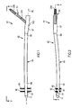
- the femoral nail or rod 62 includes an elongate body 64 that extends along a longitudinal axis 66 and can have a proximal portion or head 67, a central portion or neck 68 and a distal portion or shaft 69 that terminates at a distal tip 71.
- the elongate body 64 may curve in at least one portion of the shaft or stem 69 to align the rod 62 along the length of the marrow canal of the femur when the rod is inserted in the femur.
- the elongate body 64 can be made from any suitable material such as stainless steel, titanium or another alloy and can have a length, dependent in part on the length in which the rod 62 is to be utilized, ranging from 180 to 500 centimeters.
- the head 67 of the nail 62 can have a length ranging from four to 15 centimeters and preferably ranging from eight to 12 centimeters and a diameter ranging from eight to 20 millimeters.
- the distal-most bore 81 is elongated in its transverse direction, that is parallel to the longitudinal axis 66 of the stem 69, to permit the stem to be moved longitudinally relative to the respective distal fastener or fixation screw 82 before tightening of the fastener or screw to the underlying portion of the femur.
- At least one transverse apertures or opening 91 is provided through the head 67 of the rod 62 and in one example is angled toward the proximal end of the rod relative to longitudinal axis 66 for receiving the proximal fixation screw or fixation screw 63. More specifically, the one or more transverse apertures or holes 91 each pivotably receive a fixation screw 63 and allow for changing the angle made between the screw 63 and the nail 62. Each such aperture or first hole can extend through the head 67 in an angled direction relative to longitudinal axis 66 such that when the rod is in position within the marrow canal of the femur, axis 92 of the opening is directed toward the head of the femur (see FIG. 13 ). As can be seen from FIGS.
- the transverse aperture or aperture 92 in the head 67 can communicate with a first or lateral transverse opening 93, through which the respective fixation screw is inserted, and an opposite second or medial transverse opening 94, from which the distal portion of the screw extends.
- the medial transverse opening 94 as shown in FIGS. 5 , 8 , 11 and 13 , can be elongate or oblong in a transverse direction that is parallel to longitudinal axis 66 of head 67 and body 64, so as to accommodate pivoting of the distal portion of the proximal fixation screw 63.
- Internal threads 104 can be provided in proximal portion 102a.
- the segmented circular portion or segmented portion 102b of recess 102 may be formed from an inner arcuate surface 105.
- the other side of the recess 102, that is the side opposite of segmented portion 102b, can be formed with a first shelf 107, a second shelf 108 and a third shelf 109 that can each extend further radially inwardly than the inner arcuate surface 105 of the segmented portion 102b and can have increasingly smaller radii relative to longitudinal axis 66 (see FIGS. 11-13 ).
- the proximal portion of the first shelf 107 can be optionally provided with internal threads 111, as shown in FIGS. 4 , 9 and 10 .
- a shoulder 112 can extend radially inwardly from first shelf 107 to second shelf 108 (see FIG. 13 ).
- the third shelf 109 may abut the lateral transverse opening 93, as shown in FIG. 11 .
- Transversely aligned slots 110 may be provided on the proximal end of head 67 at proximal opening 103 for registering the nail 62 with an insertion jig, targeting device or other suitable device when placing or otherwise manipulating the nail within the targeted bone.
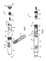
- the actuation or adjustment mechanism 101 for pivoting the proximal fixation screw 63 can be of any suitable type, in one example the mechanism 101 includes an insert or sleeve 116, a control element 117, an end or safety nut 118 and an alignment or set screw 119, as shown in the exploded views of FIGS. 5-6 and in the assembled view of FIG. 4 .
- Each of these components can be made from any suitable material such as stainless steel.
- Such transverse, cross-sectional configuration of sleeve 116 preferably approximates the cross-sectional configuration of the segmented circular portion 102b of the recess 102 in head 67 and can extend through an arc ranging from 100 to 360 degrees, preferably ranging from 180 to 240 degrees and illustrated in FIG. 16 as approximately 240 degrees.
- the elongate transverse opening 124 can be formed in the center of the insert. Such opening 124 may be oblong or elongate in shape and smaller than the medial transverse opening 94 provided in head 67 of the nail 62.
- the insert 116 may be provided with internal thread 131 extending through the bore 127 at the proximal portion 122 of the insert, such threads being adjacent the top or proximal end of the insert as shown in FIGS. 14 and 17 .
- the insert can have a length ranging from 30 to 110 millimeters and can have an external radius sized to fit within head 67 of the nail 62.
- the distal portion of internal bore 127 that is the portion of the bore distal transverse opening 124, has a smaller internal diameter than the internal diameter of the proximal portion of the bore.
- Control element 117 can be of any suitable type and in one example includes a spindle or screw 117 formed from a cylindrical body 136 provided with a distal portion 137 of constant radius and can have a smooth outer cylindrical surface 138, a central portion 139 adjacent the distal portion and having external threads 141 extending radially outwardly relative to the distal portion and a proximal or neck portion 142 adjacent the central portion (see FIGS. 18-22 ).
- the neck portion can include a proximal flange 143 and an annular recess 144 disposed between the flange and the central portion 139 of the spindle or screw 117.
- the distal end portion of the end nut may be provided with a recess or socket 172 that can be in communication with bore 171 and be side opening onto the outer cylindrical surface 163 of the distal portion 162.
- the socket 172 can be sized and configured for cooperatively receiving the neck portion 142 of the spindle 117 and may include a partial annular flange 173, shown most clearly in FIG. 24 , extending radially inwardly for partially seating in the annular recess 144 of the spindle and a partial annular recess 174 extending radially outwardly relative to the flange for receiving part of the proximal, annular flange 143 of the spindle.
- the end nut can have a length ranging from five to 50 millimeters and preferably approximately 15 millimeters.
- the proximal portion 202 may be provided with a plurality and as shown four longitudinally-extending slots 204 extending through the surface 203 in circumferentially-spaced apart positions.
- Distal portion 206 of the body 201 may be provided with external threads 207 that extend to a sharpened distal end or tip 208 of the body.
- the distal portion 206 of the body 207 may be irregularly shaped or flat (not shown).
- the body can further have a proximal end 211 and be provided with a central bore 212 that extends longitudinally through the body from the proximal end 211 to the distal end 208 (see FIG. 35 ).
- the proximal end of the central bore 212 may be provided with internal threads 213 and be formed with a drive socket 214 of any suitable type for facilitating connection of the proximal fixation screw to a drive tool of any suitable type.
- the distal end of the transverse opening 124 in the insert 116 engages the fixation screw during proximal movement of the insert within the head 67 to cause the fixation screw to pivot within the medial transverse opening 93 of the transverse aperture 91 of the head.
- the spindle 117 can rotate freely relative to the head and the end cap 118.
- the set screw 119 can be rotated distally with the spindle 117 so that the blunted end 188 of the set screw seats within one of the longitudinal slots 294 formed in the proximal portion 202 of the fixation screw 63 so as to rotatably lock the fixation screw relative to the head 67 of the intramedullary rod 62 and thus inhibit undesirable further advancement or withdrawal of the screw 63 relative to the rod 62.
- FIGS. 38-52 Another apparatus 231 is illustrated in FIGS. 38-52 and can include an intramedullary rod 232 substantially similar to rod 62. Like reference numerals have been utilized to describe like components of rods 62 and 232.
- the intramedullary rod 232 has any suitable first and second proximal fasteners, shown as first and second proximal fixation screws 233 and 234 that can each be substantially identical to proximal fixation screw 63, pivotably received within respective first and second transverse apertures 236 and 237 that can each be substantially identical to transverse aperture 91 and extend along respective axes 92.
- the first and second fasteners 233 and 234 extend parallel to each other, may or may not be of the same length and may or may not be of the same type of fastener.
- the first fastener 233 may be a screw and the second fastener 234 may be a peg or blade.
- the apertures 236 and 237 are provided in a head 239, substantially similar to head 67, of the rod 232.
- the insert 242 can have a length ranging from 20 to 120 millimeters and an external radius sized to fit within head 239 of the nail 232.
- a spindle 256 can be provided that is substantially similar to the spindle 117 but formed without the distal portion 137 of spindle 117 (see FIGS. 45-48 ). Instead, spindle 256 of the dual fixation screw rod 232 of FIGS. 38-52 has a proximal or neck portion 142 and a distal portion 257 substantially similar to central portion 139 of the spindle 117.
- the spindle 256 can have a length ranging from five to 30 millimeters.
- An end cap or nut 266 substantially similar to end nut 118 but shorter in length can be further provided (see FIGS.
- actuation assembly 241 can be loaded into head 239 of dual fixation screw rod 232, and operated therein with respect to first and second proximal fixation screws 233 and 234, in substantially the same manner as discussed above with respect to apparatus 61.
- Sleeve 242 is shown in FIG. 40 in its distal position.
- the inclusion in apparatus 241 of the second fixation screw 234 minimizes the need for a set screw, such as set screw 119, and preferably eliminates the need for such a set screw.
- the second proximal fixation screw is included in the means or mechanism of the rod 232 for preventing rotation of the head of the femur relative to the first proximal fixation screw 233 during use of rod 232.
- FIG. 53 A further example of the intramedullary rod with pivotable fasteners is illustrated in FIG. 53 wherein an apparatus 271 substantially similar to apparatus 61 and 231 is provided. Like reference numerals have been used to describe like components of apparatus 61, 231 and 271.
- Intramedullary rod or nail 272 of the apparatus 271 is substantially similar to rods 62 and 232 and has any suitable first and second proximal fasteners, shown as first and second proximal fixation screws 233 and 234.
- the first screw 233 is pivotably received within first transverse aperture 236 extending along axis 92.
- the second screw 234 is pivotably received within a second transverse aperture 273 extending along an axis 274.
- the third proximal fixation screw 283 can be identical to one or both of first and second proximal fixation screws 233 and 234, and the third transverse aperture 286 can be identical to one or both of first and second transverse apertures 236 and 237.
- the first, second and third fasteners 233, 234 and 283 may or may not extend parallel to each other, may or may not be of the same length and may or may not be of the same type of fastener. In the illustrated example, the fasteners 233, 234 and 283 extend parallel to each other.
- the apertures 236, 237 and 286 are provided in a head 287 of the rod 282 that is substantially similar to head 239 of rod 232.
- An actuation mechanism or assembly substantially similar to actuation mechanism 241 but modified to provide for the third transverse aperture 286 can be provided.
- FIGS. 55-56 Yet a further example of the intramedullary rod with pivotable fasteners is illustrated in FIGS. 55-56 wherein an apparatus 296 substantially similar to apparatus 61 and 231 is provided. Like reference numerals have been used to describe like components of apparatus 61, 231 and 296.
- Intramedullary rod or nail 297 of the apparatus 296 is substantially similar to rods 62 and 232 and has any suitable first and second proximal fasteners, shown as first and second proximal fixation screws 233 and 234.
- the first screw 233 is pivotably received within first transverse aperture 236 extending along axis 92.
- the second screw 234 is pivotably received within a second transverse aperture 298 extending along an axis 299.
- the second fixation screw 234 inhibits, if not prevents, rotation of the femoral head 326 relative to the first fixation screw 233.
- the apparatus can include more than two proximal fasteners to fixate head 326 of the femur, or a portion of any other suitable bone.
- Second fixation screw 333 and thus second aperture 341 can be proximal or distal or first aperture 91 and is shown as being distal of the first aperture 91. It is appreciated that a second or fixed fixation screw can be provided both proximally and distally of the one or more pivotable fixation screws, between the pivotable fixation screws or any combination of the foregoing. In one example, the second aperture 341 is located distally of the first aperture a distance ranging from two to 30 millimeters side to side and in another example a distance of approximately seven millimeters side to side.
- the second proximal fixation screw 333 can be disposed at any suitable angle ⁇ relative to longitudinal axis 66 of the elongate body 64.
- the screw 333 can be inclined proximally, as shown in FIGS. 60-62 , be inclined distally (not shown) or be orthogonal to the axis 66.
- the screw 333 is inclined relative to axis 66 at an angle ⁇ ranging from 90° to 170° and in another example at an angle ⁇ ranging from 120° to 140° (see FIG. 62 ).
- Apparatus 31 can be used in any suitable procedure for repairing a bone of a mammalian body, for example a femur in a leg.
- rod 332 is introduced through the greater trochanter 321 into the medullary canal 332 in the shaft 323 of the femur 311.
- Suitable holes 324 are made in the side of the greater trochanter to allow insertion of the first and second fixation screws 63 and 333 into respective first and second apertures 91 and 346 of the rod 332.
- First screw 63 can be initially introduced through rod 332 and screwed into the head 326 of the femur 311.
- the fixed screw 333 can be further advanced relative to the head 348 of the rod 332 so as to cause the first screw 63 to pivot relative to the head 348, for example to pivot the first screw 63 toward proximal opening 77 of the rod 332.
- an actuation mechanism 351 need not be provided when the fixed screw 333 is used solely as the means for pivoting the dynamic screw 63.
- the dynamic screw pivots freely relative to head 348 and is supported in its desired position by static screw 333, either solely or in combination with another suitable securement mechanism (not shown). It is also appreciated that other means can be provided for pivoting the dynamic screw 63.
- a locking mechanism for use with an implantable medical device.
- the locking mechanism can be utilized with any medical device having a rotatable, control, moveable or other element on the outside or inside thereof.
- the locking mechanism can be used with a threaded element, for example an internal or external threaded element of a medical device.
- the element can be an element for controlling another moveable element of a medical device, for example a control element coupled to a longitudinally moveable or slidable element of the medical device.
- the medical device is an implantable intramedullary rod.
- a first or lateral transverse opening 421 is provided on one side of wall 413 or first side portion 413a of the wall and a second or medial transverse opening 422 is provided on the other side of the wall 413 or second side portion 413b of the wall.
- At least one of the openings 421 and 422 can be elongate or oblong in a direction parallel to longitudinally axis 404 so as to facilitate pivoting of the fixation screw 63 relative to head 406 about an axis (not shown) extending orthogonally to longitudinally axis 404 and aperture axis 417.
- the lateral transverse opening 421 is so elongate or oblong.
- Axis 417 is centered on aperture 416 and can extend relative to longitudinal axis 404 at an angle and in one embodiment at an angle of approximately 140 degrees measured from the portion of head 406 distal of head aperture 416.
- Annulus forms the periphery of the proximal portion 441a, and of the elongate member 441, and is substantially circular in shape.
- Lip 447 extends around the periphery of the proximal portion 441a, but is provided with an opening or cutout 449 at the top thereof such that the lip 447 does not extend around the top of elongate member 441.
- Elongate member 441 is provided with an elongate cutout 451 extending distally of annulus 446, and the cutout 451 is formed by a flat 452 which is planar and parallel to central axis 442.
- a concave arcuate surface 453 extends from each side of the flat 452 to bottom surface 443.
- distal portion 441b of the sleeve 436 is noncircular in cross section and in one embodiment its segmented circular cross section, as described above, corresponds generally with the cross section of segmented portion 412c of the head proximal recess 412.
- Distal portion 441b of the elongate member 441 is sized and shaped to slidably move longitudinally within segmented circular portion 412c of the proximal recess 412 of the head 406.
- Annulus 446 of the sleeve of 436 is externally sized and shaped to slidably move longitudinally move within central portion 412b of the head proximal recess 412.
- At least one of the openings 463 and 464 can be elongate or oblong in a direction parallel to central axis 442 so as to facilitate pivoting of the fixation screw 63 relative to head 406 and sleeve 436 about an axis (not shown) extending orthogonally to sleeve central axis 442 and aperture axis 462.
- medial transverse opening 464 is so provided with a cutout at its distal portion so as to be elongate or oblong.
- Axis 462 can be centered on aperture 461 and can extend relative to central axis 442 at an angle and in one embodiment at the same angle that axis 417 extends relative to longitudinal axis 404.
- worm gear 437 can be rotated in a clockwise direction from proximal opening 10.3 so as to cause sleeve 436 to move distally within the head 406, and rotated in a counter-clockwise direction from proximal opening 103 so as to cause the sleeve 436 to move proximally within the head 406.
- the diameter of drive socket 479 is larger than the diameter of the internally-threaded proximal portion of longitudinal bore 456 of the sleeve 439 and is preferably coaxially aligned with sleeve bore 456.
- Nut 486 has a distal surface 498 which includes flange 496 and in one embodiment the surface 498 is planar and orthogonal to central axis 488.
- a plurality of locking or engagement means or elements are provided on distal surface 498 and can be of any suitable type, including a plurality of recesses, protuberances or a combination of recesses and protuberances.
- such locking means includes a plurality of first upstanding protuberances or dogs 501 extending longitudinally outwardly from the distal surface 498.
- a plurality of first dogs 501 are spaced circumferentially around surface 498 and in one embodiment the first dogs 501 are circumferentially spaced equally apart around the distal surface 498.
- the second drive element 487 is annular in shape and can be an annular element.
- the second drive element can be in the form of a washer having opposite first and second planar surfaces 506, 507 extending parallel to each other and a bore 508 extending between the surfaces 506 and 507.
- the washer 487 has an outer diameter smaller than the inner diameter of threaded portion 412a of the head proximal recess 412. Similar to distal surface 498 of nut 486, first surface 506 of the washer is provided with a plurality of locking or engagement means or elements of any suitable type, including a plurality of recesses, protuberances or a combination of recesses and protuberances.
- such locking means include a plurality of second upstanding protuberances or dogs 509 extending longitudinally outwardly from the first surface 506.
- the plurality of second protuberances 509 are spaced circumferentially around the first surface 506 and in one embodiment the second dogs circumferentially spaced apart so as to register with or engage first dogs 501 and thus preclude relative to rotation between washer 47 and nut 46 when the washer 487 and second dogs 509 are in the first position. In this manner, second dogs 509 cooperatively engage first dogs 501 when washer 487 is in the first position.
- Locking mechanism 439 can further include a driver element or driver 511 having a proximal portion 511a with a circular outer surface and a distal portion or drive head 511b with an outer surface that is non-circular in cross section.
- the diameter or at least the distal portion of the circular outer surface approximates the diameter of the inner circular surface of nut flange 496.
- the cross-sectional shape of distal end or drive head 511b can be, for example, triangular, square, hexagonal or octagonal, and preferably corresponds in size and configuration and cooperates with drive socket 479 of the worm gear 437.
- a flange 512 extends radially outwardly from proximal portion 511a at the proximal end of driver 511.
- Flange 512 has an outer circular surface with a diameter that approximates the diameter of the inner circular surface 491 of nut 486.
- a drive socket 513 extends longitudinally inwardly from the proximal end of driver 511 and preferably has a cross section which is non-circular in shape, for example similar to the cross-sectional shape of drive head 511b discussed above, so that when the socket 513 is engaged by a suitable tool it can serve to cause rotation of the driver 511.
- a longitudinally-extending bore 514 extends distally from drive socket 513 through the remainder of the driver 511.
- driver 511 extends through nut 486 and washer 487. More specially, the driver 511 extends through bore 493 and flange 496 of the nut 486 until the nut flange 496 is in close proximity to driver proximal portion 511a and driver flange 512 is seated within bore 493 and in one embodiment flush with the proximal end of nut 486. In one embodiment, flange 496 of the nut engages the outer circular periphery of proximal portion 511a of the driver 511.
- Washer 487 extends around distal portion or end of driver proximal portion 511a distal of nut 46 so that when locking mechanism 439 is in its first or rest position second dogs 509 of washer 487 are cooperatively engaged and locked with first dogs 501 of nut 486.
- the washer 487 is secured to proximal portion 511 a of the driver by any suitable means such as welding. Nut 486 is not secured to driver 511 and thus longitudinally moveable relative to the driver.
- Locking mechanism 439 is movable between a first position in which driver 511 can rotate freely relative to nut 486 and a second position in which the driver 511 is rotatably locked with the nut 486.
- Spring 517 urges locking mechanism 439 towards its first or rest position, illustrated in FIGS. 76 and 82 , in which the springs 517 urges flange 512 of the driver 511 longitudinally away from flange 496 of nut 486 so that second dogs 509 on first surface 506 of washer 487 register and rotatably lock with first dogs 501 on distal surface 498 of the nut 46.
- driver 511 When driver 511 is urged longitudinally in a distal direction, for example by insertion of a suitable drive tool in drive socket 513 of the driver 511 and exertion of a longitudinal force in the distal direction on the tool and thus the driver 511, washer 487 that is rigidly secured proximal portion driver 511a of the driver is moved longitudinally against the force of spring 517 away from distal surface 498 of nut 486 so that the second dogs 509 of the washer 487 separate and disengage from first dogs 501 of the nut 46 to a second or disengaged position, illustrated in FIG. 83 , in which the combined driver 511 and washer 487 unit can be rotated relative to nut 486. As such, washer 487 is spaced longitudinally from nut 486 when the washer is in its second position.
- Set screw 438 can be of any suitable type and similar to set screw 119 discussed above.
- set screw 438 is cylindrical in conformation and externally threaded.
- the set screw 438 can include a rounded distal end 522 and a suitable drive socket 523 provided at its proximal end.
- Such set screw is diametrically sized so as to be capable of being passed longitudinally through drive socket 513 and bore 514 of drive 511 and into bore 456 of the sleeve 436 to threadably engage the threaded proximal portion 45ba of the sleeve bore 456.
- head 406 can be loaded in proximal recess 412 of the head in any suitable manner.
- sleeve 436 is introduced through threaded portion of 412a so that distal portion 441b of the sleeve is seated within segmented portion 412c of the recess 412 and annulus 446 of the sleeve is seated within central portion 412b of the recess 412.
- distal portion 441b has an external cross section similar to the internal cross section of segmented portion 412c so that sleeve 436 is rotatably locked but longitudinally movable or slidable in nail 402 relative to axis 404 of the nail.
- Aperture 461 of sleeve 436 is generally registered with aperture 416 of head 406 in the operational longitudinally positions of sleeve 436 within the nail head 406.
- nut 486 of the locking mechanism is secured to the head 406 and in one embodiment locked or secured against both rotatable and longitudinally movement within the head 406.
- the engaged invisible internal threads of threaded portion 412a of the head 406 and external threads at the proximal end of nut 486 are punched at one or more positions, for example at a plurality of circumferentially-spaced apart positions, by a suitable punching tool so as to preclude nut 46 from being rotatably moved in a proximal direction, and thus withdrawn, from threaded portion 412a of recess 412.
- Nail 402 can be placed within a bone in any suitable manner and for example as discussed above and as discussed below.
- a guide wire is first introduced into the bone and the nail is then threaded over the proximal end of the guide wire for proper placement and positioning in the bone.
- the proximal end of the guide wire can be inserted through passageway 76 of the elongate body 403, though adjustment mechanism 411 by means of bore 456 of sleeve 436 and drive socket 479 of worm gear 437, and through locking mechanism 439 by means of bore 514 and drive socket 513 of driver 511.
- the guide wire is removed from the nail 402 through proximal opening 103.
- a suitable fastener such fixation screw 63 can be introduced through head 406 by means of lateral transverse opening 421, aperture 461 of sleeve 436 and medial transverse opening 422 and properly positioned within the bone.
- lateral transverse opening 421 in first side portion 413a of wall 413 receives the proximal portion or head 67 of the fastener and medial transverse opening 422 in second side portion 413b of wall 413 receives the distal portion or shaft 69 of the fastener 63.
- fixation screw 63 can be pivoted relative to head 406 and central axis 404 through a range of angles by means of adjustment mechanism 411.
- the drive tool In order to rotatably unlock locking mechanism 439 and worm gear 437 that rotates one-to-one with driver 511 of the locking mechanism, so as to permit longitudinal movement of sleeve 437 within head 406, the drive tool is urged distally in drive socket 513 relative to head 406 so as to cause the driver 511 to move longitudinally along axis 404 and thus cause washer second dogs 509 to longitudinally separate and disengage from nut first dogs 501 in the manner discussed above.
- the drive tool can be used to rotate driver 511 freely of nut 486 and head 406 so as to rotate worm gear 437 and thus cause the worm gear and sleeve 436 coupled to the worm gear to move longitudinally within recess 412.
- the portion of the fixation screw 63 extending through aperture 461 of the elongate member 441 is constrained by sleeve 436, longitudinal movement of the sleeve relative to head 406 causes the fixation screw to pivot about medial transverse opening 422 of the head 406.
- Such structure also enhances retention of the fixation screw 63 in the desired angular position relative to nail head 406, for example after completion of the insertion and positioning of the nail 402 within a bone of a mammalian body and the head 326 of the bone is placed under load when the mammalian body is standing or walking so as to be urging head 326 of the bone into varus and thus exerting a moment on screw 63 in a clockwise direction in FIGS. 67 , 68 , 80 and 81 .
- rounded contact or support surface 428 of nail head 406 engages one side of the shaft 69 of screw 63 and rounded contact surface 471 of sleeve 436 engages the other side of the head 67 of screw 63 in longitudinally spaced apart positions along the length of the screw 63.
- the location of rounded contact surface 471 relatively close to the other side of nail head 406, and outer wall 413 of the head 406, from nail contact surface 428 provides a relatively large pivot arm for reducing the force exerted on each of surfaces 428 and 471.
- fixation screw 63 can be pivoted from a first or first extreme position, for example at an angle of approximately 120 degrees relative to head 406 of the nail 402 as shown in FIG. 68 , to an intermediate position, for example at an angle of approximately 130 degrees relative to head 406 as shown in FIG. 80 , to a second or second extreme position, for example at an angle of 140 degrees relative to head as shown in FIG. 81 .
- fixation screw 63 is further supported during loading by the engagement of cutout surface 426 with screw 63 adjacent rounded contact surface 471 of sleeve 436.
- screw 63 is extensively supported by the relatively flush engagement of the screw 63, now in relative alignment with aperture axis 417 of nail 402 and aperture axis 462 of sleeve 436, by nail circular inner surface 423 forming nail aperture 416 and by sleeve circular inner surface 466 forming sleeve aperture 461.
- set screw 438 can be inserted through the driver 511 into the internally threaded proximal portion 456a of sleeve bore 456 and advanced distally until the rounded end 522 of the set screw engages the fixation screw 63 to lock the fixation screw in its desired angled position and inhibit further pivoting or rotation of the screw 63 within apertures 416 and 461.
- rounded end 522 of the set screw 438 seats within one of the longitudinal slots 204 of the fixation screw 63 for enhancing the rotatable locking of the screw 63 within nail head 406.
- the head of the device can be secured to a targeting assembly or targeting device for inserting the implantable device into a mammalian body.
- a targeting assembly or targeting device for inserting the implantable device into a mammalian body.
- the implantable device is an intramedullary rod or nail, such as nail 402
- the rod or nail can be secured to a distal portion of a targeting assembly or jig and then directed or placed into the mammalian body with such targeting assembly.
- Housing 536 can have a proximal or upper end 541 provided with a proximal or upper opening 542 to socket 537 for inserting the fastening element 538 into the socket and distal or lower end 543 provided a distal or lower opening 544 through which a portion of the fastening element 538 can extend for securing to the nail head 406.
- Lower end 543 of the housing 536 is sized and shaped to cooperatively engage with the proximal end and proximal opening of nail head 406.
- the lower opening 544 has a diameter approximating the diameter of the proximal opening 103 of nail head 406.
- Housing 536 can be further provided with a registering element or key 551 which is cooperatively sized and shaped to snuggly seat within a recess or notch 552 provided on the proximal end of the nail head 406 so as to rotatably lock and register the housing 536 and thus targeting device 531 with the nail head 406 and thus nail 402.
- Fastening element 538 can be of any suitable type and in one embodiment is a cylindrical nut 538 having a diameter closely approximating but slightly smaller than the diameter of bore or socket 537 in housing 536.
- Nut can be provided with a through hole 556 extending therethrough.
- a suitable drive socket 557 can be provided at the proximal end of the hole 556 for receiving any suitable drive element (not shown) for rotating the nut within housing 536.
- the exterior of the distal end 558 of nut 538 necks down to a smaller diameter at annular surface 559 and is provided with external threads 561 for cooperatively engaging and threading with internal threads 104 at the proximal end of nail head 406.
- Housing 536 is provided with an annular seat or surface 562 in socket 537 for receiving and engaging the annular surface 559 of the nut 538.
- the distal end 558 of nut 538 has a suitable actuation element of any suitable type such as a cylindrical extension 566 which protrudes distally from such end 558.
- the extension 566 can have an external diameter less than the internal diameter of nut 486 of the locking mechanism 439 so as to engage flange 512 of driver 511 of the locking mechanism and simultaneously move the driver 511 distally from its first or locked position, illustrated in FIG. 82 , to its second or unlocked position, illustrated in FIG. 83 , as the nut 538 of the targeting device 531 is screwed into the proximal end of the nail head 406.
- the mere coupling or connecting of the targeting device 531 to the nail unlocks the locking mechanism 439 of the nail and permits the angle of the transverse aperture 416 of the nail, and thus fastener or screw 63, to be adjusted relative to the central axis 404 of the nail.
- pivoting of the fastener 63 is caused by inserting a suitable drive element through nut 538 and housing 536 of the connector 534 into drive socket 513 of driver 511.
- the locking mechanism 439 Prior to such connecting of the targeting assembly 531 to the nail 402 or other implantable device, the locking mechanism 439 is in its locked position so as to preclude angular adjustment of transverse aperture 416 or any fastener 63 therein..
Landscapes
- Health & Medical Sciences (AREA)
- Orthopedic Medicine & Surgery (AREA)
- Surgery (AREA)
- Life Sciences & Earth Sciences (AREA)
- Heart & Thoracic Surgery (AREA)
- Nuclear Medicine, Radiotherapy & Molecular Imaging (AREA)
- Engineering & Computer Science (AREA)
- Biomedical Technology (AREA)
- Neurology (AREA)
- Medical Informatics (AREA)
- Molecular Biology (AREA)
- Animal Behavior & Ethology (AREA)
- General Health & Medical Sciences (AREA)
- Public Health (AREA)
- Veterinary Medicine (AREA)
- Surgical Instruments (AREA)
Description
- The present invention relates to apparatus for affixing to bones and, more particularly, to an implantable device with adjustable members for affixing to bones.
- There are a variety of devices for affixing to bones. Such devices can include, for example, spinal fasteners, bone plates and intramedullary rods used to treat femoral and other bone fractures. Peritochanteric fractures of the femur, for example, have been treated with femoral rod assemblies that for example are inserted into the femoral canal to coapt the femur fracture parts. One or two angled cross-nails or locking screws are inserted through the femur and the proximal end of the intramedullary rod.
- Currently available nails have been provided with static angled screws that transverse the femoral nail and then achieve adequate fixation strength in the head of the femur. They may also have slots in the nail that allow for dynamic controlled or uncontrolled compression of the fracture site in fractures of the subtrochanteric region and below, either with or without an over sleeve. Frequently, devices that treat femoral neck, intertrochanteric, and subtrochanteric fractures have varying static angles that necessitate an increased inventory to accommodate for varied static angles of the nail.
-
US 2009/048600 discloses an example of an intramedullary rod for use with a fastener to repair a femur. The rod includes a nail with a longitudinal axis, a stem and a head. The head is provided with an aperture at an angle to the longitudinal axis for receiving the fastener. A mechanism is carried by the head for pivoting the axis of the aperture. -
US 2008/077142 describes a device for treating femoral fractures with a polyaxial cross member which can accommodate a range of angles and anteversions/retroversions in the femur. - The present invention is defined in
claim 1. - The drawings described herein are for illustration purposes only and are not intended to limit the scope of the present disclosure in any way.
-
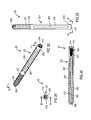
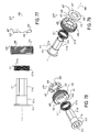
FIG. 1 is a front view of one embodiment of an intramedullary rod with pivotable fastener of the present invention. -
FIG. 2 is a side view of the intramedullary rod with pivotable fastener ofFIG. 1 taken along the line 2-2 ofFIG. 1 . -
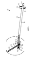
FIG. 3 is a rear view, partially sectioned, of the intramedullary rod with pivotable fastener ofFIG. 1 taken along the line 3-3 ofFIG. 2 . -
FIG. 4 is an enlarged cross sectional view of the intramedullary rod with pivotable fastener ofFIG. 1 taken along the line 4-4 ofFIG. 3 . -
FIG. 5 is an exploded view of the head of the intramedullary rod with pivotable fastener ofFIG. 1 . -
FIG. 6 is a side exploded view of the head of the intramedullary rod with pivotable fastener ofFIG. 1 taken along the line 6-6 ofFIG. 5 . -
FIG. 7 is a front view of the nail of the intramedullary rod with pivotable fastener ofFIG. 1 with the components of the actuation mechanism removed. -
FIG. 8 is a side view of the nail ofFIG. 7 taken along the line 8-8 ofFIG. 7 . -
FIG. 9 is a cross-sectional view of the nail ofFIG. 7 taken along the line 9-9 ofFIG. 7 . -
FIG. 10 is a cross-sectional view of the proximal portion of the nail ofFIG. 7 taken along the line 10-10 ofFIG. 8 . -
FIG. 11 is a side view of the head of the nail ofFIG. 7 taken along the line 11-11 ofFIG. 10 . -
FIG. 12 is a top end view of the nail ofFIG. 7 taken along the line 12-12 ofFIG. 11 . -
FIG. 13 is a cross-sectional view of the proximal portion of the nail ofFIG. 7 taken along the line 13-13 ofFIG. 12 . -
FIG. 14 is a perspective view of the insert of the intramedullary rod with pivotable fastener ofFIG. 1 . -
FIG. 15 is a top view of the insert ofFIG. 14 taken along the line 15-15 ofFIG. 14 . -
FIG. 16 is an end view of the insert ofFIG. 14 taken along the line 16-16 ofFIG. 15 . -
FIG. 17 is a cross-sectional view of the insert ofFIG. 14 taken along the line 17-17 ofFIG. 16 . -
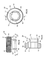
FIG. 18 is a perspective view of the end nut of the intramedullary rod with pivotable fastener ofFIG. 1 . -
FIG. 19 is a side view of the end nut ofFIG. 18 taken along the line 19-19 ofFIG. 18 . -
FIG. 20 is bottom end view of the end nut ofFIG. 18 taken along the line 20-20 ofFIG. 18 . -
FIG. 21 is top end view of the end nut ofFIG. 18 taken along the line 21-21 ofFIG. 19 . -
FIG. 22 is a cross-sectional view of the end nut ofFIG. 18 taken along the line 22-22 ofFIG. 21 . -
FIG. 23 is a perspective view of the spindle of the intramedullary rod with pivotable fastener ofFIG. 1 . -
FIG. 24 is a side view of the spindle ofFIG. 23 taken along the line 24-24 ofFIG. 23 . -
FIG. 25 is top end view of the spindle ofFIG. 23 taken along the line 25-25 ofFIG. 24 . -
FIG. 26 is bottom end view of the spindle ofFIG. 23 taken along the line 26-26 ofFIG. 24 . -
FIG. 27 is a cross-sectional view of the spindle ofFIG. 23 taken along the line 27-27 ofFIG. 25 . -
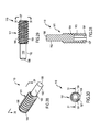
FIG. 28 is a perspective view of the set screw of the intramedullary rod with fastener ofFIG. 1 . -
FIG. 29 is a side view of the set screw ofFIG. 28 taken along the line 29-29 ofFIG. 28 . -
FIG. 30 is an end view of the set screw ofFIG. 28 taken along the line 30-30 ofFIG. 29 . -
FIG. 31 is a cross-sectional view of the set screw ofFIG. 28 taken along the line 31-31 ofFIG. 30 . -
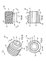
FIG. 32 is a perspective view of the fastener of the intramedullary rod with fastener ofFIG. 1 , -
FIG. 33 is a side view of the fastener ofFIG. 32 taken along the line 33-33 ofFIG. 32 . -
FIG. 34 is an end view of the fastener ofFIG. 32 taken along the line 34-34 ofFIG. 33 . -
FIG. 35 is a cross-sectional view of the fastener ofFIG. 32 taken along the line 35-35 ofFIG. 34 . -
FIG. 36 is a front view of the proximal portion of the intramedullary rod with pivotable fastener ofFIG. 1 showing the fastener in the first position ofFIG. 1 relative to the intramedullary rod and the fastener in a second position relative pivoted counterclockwise to the intramedullary rod. -
FIG. 37 is a cross-sectional view of the proximal portion of the intramedullary rod and pivotable fastener ofFIG. 1 showing the fastener in a third position relative to the intramedullary rod. -
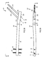
FIG. 38 is a front view of another example of an intramedullary rod with pivotable fasteners. -
FIG. 39 is a side view of the intramedullary rod with pivotable fasteners ofFIG. 38 taken along the line 39-39 ofFIG. 38 . -
FIG. 40 is a cross-sectional view of the intramedullary rod with pivotable fasteners ofFIG. 38 taken along the line 40-40 ofFIG. 39 . -
FIG. 41 is a perspective view of the insert of the intramedullary rod with pivotable fasteners ofFIG. 38 . -
FIG. 42 is a top view of the insert ofFIG. 41 taken along the line 42-42 ofFIG. 41 . -
FIG. 43 is an end view of the insert ofFIG. 41 taken along the line 43-43 ofFIG. 42 . -
FIG. 44 is a cross-sectional view of the insert ofFIG. 41 taken along the line 44-44 ofFIG. 43 . -
FIG. 45 is a perspective view of the spindle of the intramedullary rod with pivotable fasteners ofFIG. 38 . -
FIG. 46 is a side view of the spindle ofFIG. 45 taken along the line 46-46 ofFIG. 45 . -
FIG. 47 is an end view of the spindle ofFIG. 45 taken along the line 47-47 ofFIG. 46 . -
FIG. 48 is a cross-sectional view of the spindle ofFIG. 45 taken along the line 48-48 ofFIG. 47 . -
FIG. 49 is a side view of the set screw of the intramedullary rod with pivotable fasteners ofFIG. 38 . -
FIG. 50 is an end view of the set screw ofFIG. 49 taken along the line 50-50 ofFIG. 49 . -
FIG. 51 is a cross-sectional view of the set screw ofFIG. 49 taken along the line 51-51 of FIX. 50. -
FIG. 52 is a perspective view of the set screw ofFIG. 49 mounted on the spindle ofFIG. 45 . -
FIG. 53 is a front view of a distal portion of a further example of an intramedullary rod with pivotable fasteners. -
FIG. 54 is a front view of a distal portion of a yet another example of an intramedullary rod with pivotable fasteners. -
FIG. 55 is a side view of a distal portion of a yet a further example of an intramedullary rod with pivotable fasteners. -
FIG. 56 is an end view of the intramedullary rod with pivotable fastener ofFIG. 55 taken along the line 56-56 ofFIG. 55 . -
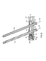
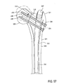
FIG. 57 is a schematic front view of the intramedullary rod with pivotable fasteners ofFIG. 38 disposed in a femur to repair a femoral neck fracture. -
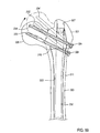
FIG. 58 is a schematic front view of the intramedullary rod with pivotable fasteners ofFIG. 38 disposed in a femur to repair an intertrochanteric fracture. -
FIG. 59 is a schematic front view of the intramedullary rod with pivotable fasteners ofFIG. 38 disposed in a femur to repair a subtrochanteric fracture. -
FIG. 60 is a front view an example of an intramedullary rod with pivotable and fixed fasteners. -
FIG. 61 is a side view of the intramedullary rod with pivotable and fixed fasteners ofFIG. 60 taken along the line 61-61 ofFIG. 60 . -
FIG. 62 is an enlarged cross sectional view of the intramedullary rod with pivotable and fixed fasteners ofFIG. 60 taken along the line 62-62 ofFIG. 61 and including another example of the fixed fastener. -
FIG. 63 is a top view, similar toFIG. 15 , of the insert of the intramedullary rod with pivotable and fixed fasteners ofFIG. 60 . -
FIG. 64 is an end view of the insert ofFIG. 63 taken along the line 64-64 ofFIG. 63 . -
FIG. 65 is a rear view of an embodiment of an intramedullary rod with pivotable fastener of the present invention. -
FIG. 66 is a top end view of the intramedullary rod with pivotable fastener ofFIG. 65 taken along the line 66-66 ofFIG. 65 . -
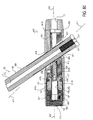
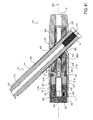
FIG. 67 is a cross-sectional view of the intramedullary rod with pivotable fastener ofFIG. 65 taken along the line 67-67 ofFIG. 66 . -
FIG. 68 is an enlarged cross sectional view of the intramedullary rod with pivotable fastener ofFIG. 65 taken along the line 68-68 ofFIG. 67 . -
FIG. 69 is a side view of the insert of the intramedullary rod with pivotable fastener ofFIG. 65 . -
FIG. 70 is a top end view of the insert ofFIG. 69 taken along the line 70-70 ofFIG. 69 . -
FIG. 71 is a cross-sectional view of the insert ofFIG. 69 taken along the line 71-71 ofFIG. 70 . -
FIG. 72 is a perspective view of the insert ofFIG. 69 . -
FIG. 73 is a side view of the locking mechanism of the intramedullary rod with pivotable fastener ofFIG. 65 . -
FIG. 74 is a bottom end view of the locking mechanism ofFIG. 73 taken along the line 74-74 ofFIG. 73 . -
FIG. 75 is a top end view of the locking mechanism ofFIG. 73 taken along the line 75-75 ofFIG. 73 . -
FIG. 76 is a cross-sectional view of the locking mechanism ofFIG. 73 taken along the line 76-76 ofFIG. 75 . -
FIG. 77 is a side exploded view of the locking mechanism ofFIG. 73 . -
FIG. 78 is a first perspective view of the exploded locking mechanism ofFIG. 73 . -
FIG. 79 is a second perspective view of the exploded locking mechanism ofFIG. 73 . -
FIG. 80 is an enlarged cross sectional view, similar toFIG. 68 , of the intramedullary rod ofFIG. 65 with the pivotable fastener in a second position. -
FIG. 81 is an enlarged cross sectional view, similar toFIG. 68 , of the intramedullary rod ofFIG. 65 with the pivotable fastener in a third position. -
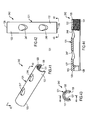
FIG. 82 is an enlarged cross-sectional view of a portion of intramedullary rod ofFIG. 68 coupled to a connector of a targeting assembly with the locking mechanism in a first position. -
FIG. 83 is a cross-sectional view, similar toFIG. 82 , with the locking mechanism in a second position. - In general, an apparatus or device is provided for treating fractures, nonunions or malunions of the femur or other bones of a mammalian body and includes an intramedullary rod or nail and at least one fastener carried by the rod. At least one opening is provided in the head of the apparatus for slidably receiving the one or more fasteners and permitting the fastener or fasteners to pivot relative to the head of the apparatus.
- In one example, the
apparatus 61 comprises anintramedullary rod 62 and aproximal fastener 63 pivotably carried by the proximal portion of the rod (seeFIGS. 1-3 ). Theproximal fastener 63 can be of any suitable type, including a fixation screw, a screw, a peg, a helical blade or any other fixation device, and for simplicity is referred to herein as a fixation screw. The femoral nail orrod 62 includes anelongate body 64 that extends along alongitudinal axis 66 and can have a proximal portion orhead 67, a central portion orneck 68 and a distal portion orshaft 69 that terminates at adistal tip 71. Theelongate body 64 may curve in at least one portion of the shaft or stem 69 to align therod 62 along the length of the marrow canal of the femur when the rod is inserted in the femur. Theelongate body 64 can be made from any suitable material such as stainless steel, titanium or another alloy and can have a length, dependent in part on the length in which therod 62 is to be utilized, ranging from 180 to 500 centimeters. Thehead 67 of thenail 62 can have a length ranging from four to 15 centimeters and preferably ranging from eight to 12 centimeters and a diameter ranging from eight to 20 millimeters. - A longitudinally-extending passageway or bore 76, shown in part in
FIGS. 3-4 and9-10 , can be provided and extends from aproximal opening 77 in thehead 67 to anopening 78 in the tip of the stem for permitting the rod to slide along a guide wire during insertion of the rod into the femur. The curve of thelongitudinal axis 66, and thus the curve of thestem 69 of therod 62, can be through a single plane or through multiple planes. In the illustrated example ofnail 62, as shown inFIGS. 8, 10 ,12 and 13 , the curve ofbody 64 extends through multiple planes. At least one and in one example first andsecond bores 81, which can extend perpendicular to thelongitudinal axis 66, are provided in the distal end portion of thestem 69 adjacent the taperedtip 71 of the stem. The bores are sized to receive respective distal fasteners, such as fixation screws, screws, pegs, helical blades or any other suitable fixation devices, and in one example such distal fasteners are in the form of fixation screws orscrews 82 that can be fixed at an orthogonal angle relative to stem 69. In the illustrated example and as shown inFIGS. 1-2 and7-9 , the distal-most bore 81 is elongated in its transverse direction, that is parallel to thelongitudinal axis 66 of thestem 69, to permit the stem to be moved longitudinally relative to the respective distal fastener orfixation screw 82 before tightening of the fastener or screw to the underlying portion of the femur. - At least one transverse apertures or
opening 91 is provided through thehead 67 of therod 62 and in one example is angled toward the proximal end of the rod relative tolongitudinal axis 66 for receiving the proximal fixation screw orfixation screw 63. More specifically, the one or more transverse apertures or holes 91 each pivotably receive afixation screw 63 and allow for changing the angle made between thescrew 63 and thenail 62. Each such aperture or first hole can extend through thehead 67 in an angled direction relative tolongitudinal axis 66 such that when the rod is in position within the marrow canal of the femur,axis 92 of the opening is directed toward the head of the femur (seeFIG. 13 ). As can be seen fromFIGS. 5, 6 and10-13 , the transverse aperture oraperture 92 in thehead 67 can communicate with a first or lateraltransverse opening 93, through which the respective fixation screw is inserted, and an opposite second or medialtransverse opening 94, from which the distal portion of the screw extends. The medialtransverse opening 94, as shown inFIGS. 5 ,8 ,11 and 13 , can be elongate or oblong in a transverse direction that is parallel tolongitudinal axis 66 ofhead 67 andbody 64, so as to accommodate pivoting of the distal portion of theproximal fixation screw 63. - The
head 67 ofrod 62 may include an actuation or adjustment mechanism orassembly 101 for selectively pivoting theproximal fixation screw 63 within the transverse aperture 91 (seeFIGS. 4-31 ). In this regard, the proximal portion of thecentral passageway 76 of thenail 62 can be hollowed to form a longitudinally-extendingproximal recess 102 in the head that communicates with aproximal opening 103 in the head. As illustrated inFIGS. 12 and 13 , therecess 102 can have aproximal portion 102a, adjacent theproximal opening 103, and a segmentedcircular portion 102b that extends in cross section through any suitable angle preferably ranging from 180 to 240 degrees and illustrated inFIG. 12 as approximately 240 degrees, along the inside of thehead 67 adjacent the medialtransverse opening 94.Internal threads 104 can be provided inproximal portion 102a. The segmented circular portion orsegmented portion 102b ofrecess 102 may be formed from an innerarcuate surface 105. The other side of therecess 102, that is the side opposite ofsegmented portion 102b, can be formed with afirst shelf 107, asecond shelf 108 and athird shelf 109 that can each extend further radially inwardly than the innerarcuate surface 105 of thesegmented portion 102b and can have increasingly smaller radii relative to longitudinal axis 66 (seeFIGS. 11-13 ). The proximal portion of thefirst shelf 107 can be optionally provided withinternal threads 111, as shown inFIGS. 4 ,9 and 10 . Ashoulder 112 can extend radially inwardly fromfirst shelf 107 to second shelf 108 (seeFIG. 13 ). Thethird shelf 109 may abut the lateraltransverse opening 93, as shown inFIG. 11 . Transversely alignedslots 110 may be provided on the proximal end ofhead 67 atproximal opening 103 for registering thenail 62 with an insertion jig, targeting device or other suitable device when placing or otherwise manipulating the nail within the targeted bone. - Although the actuation or
adjustment mechanism 101 for pivoting theproximal fixation screw 63 can be of any suitable type, in one example themechanism 101 includes an insert orsleeve 116, acontrol element 117, an end orsafety nut 118 and an alignment or setscrew 119, as shown in the exploded views ofFIGS. 5-6 and in the assembled view ofFIG. 4 . Each of these components can be made from any suitable material such as stainless steel. - Elongate insert or
sleeve 116, as illustrated inFIGS. 14-17 , may be formed from a tubular-like member 121 that can have aproximal portion 122 and adistal portion 123 and a longitudinally-extendingopening 124 extending through one side.Sleeve 116 can have the shape of a cylinder with anelongate cutout 126 provided along one side thereof,opposite opening 124, that communicates with thelongitudinal bore 127 extending therethrough from proximal ortop end 128 and distal orbottom end 129. The planar top and bottom ends can extend parallel to each other. As such,sleeve 116 has a segmented circular or C shape when viewed from an end along its longitudinal axis, as shown inFIG. 16 . Such transverse, cross-sectional configuration ofsleeve 116 preferably approximates the cross-sectional configuration of the segmentedcircular portion 102b of therecess 102 inhead 67 and can extend through an arc ranging from 100 to 360 degrees, preferably ranging from 180 to 240 degrees and illustrated inFIG. 16 as approximately 240 degrees. The elongatetransverse opening 124 can be formed in the center of the insert.Such opening 124 may be oblong or elongate in shape and smaller than the medialtransverse opening 94 provided inhead 67 of thenail 62. Theinsert 116 may be provided withinternal thread 131 extending through thebore 127 at theproximal portion 122 of the insert, such threads being adjacent the top or proximal end of the insert as shown inFIGS. 14 and 17 . The insert can have a length ranging from 30 to 110 millimeters and can have an external radius sized to fit withinhead 67 of thenail 62. The distal portion ofinternal bore 127 that is the portion of the bore distaltransverse opening 124, has a smaller internal diameter than the internal diameter of the proximal portion of the bore. -
Control element 117 can be of any suitable type and in one example includes a spindle or screw 117 formed from acylindrical body 136 provided with adistal portion 137 of constant radius and can have a smooth outercylindrical surface 138, acentral portion 139 adjacent the distal portion and havingexternal threads 141 extending radially outwardly relative to the distal portion and a proximal orneck portion 142 adjacent the central portion (seeFIGS. 18-22 ). The neck portion can include aproximal flange 143 and anannular recess 144 disposed between the flange and thecentral portion 139 of the spindle orscrew 117. The cylindrical body can further include a proximal ortop end 147 and a distal orbottom end 148, as shown inFIG. 22 . The planar ends 148 and 148 may extend parallel to each other. A central passageway or bore 151 can extend through the spindle. The distal portion of the central passageway may be provided withinternal thread 152 and the proximal portion of the central passageway may be provided with any suitable cross-sectional configuration for serving as adrive socket 153. The spindle can have a length ranging from five to 50 millimeters and preferably approximately 15 millimeters. -
End nut 118 can be formed from acylindrical body 161 provided with adistal portion 162 of constant radius and a smoothouter surface 163 and aproximal portion 164 adjacent the distal portion and havingexternal threads 166 extending radially outwardly relative to the distal portion (seeFIGS. 23-27 ). The cylindrical body can further include a proximal ortop end 167 and a distal orbottom end 168, as shown inFIG. 27 . Planar ends 167 and 168 can extend parallel to each other. A central passageway or bore 171 can extend longitudinally through the end nut between ends 167 and 168 and at least the proximal portion of thebore 171 can be provided with any suitable cross-sectional configuration for serving as a drive socket. The distal end portion of the end nut may be provided with a recess orsocket 172 that can be in communication withbore 171 and be side opening onto the outercylindrical surface 163 of thedistal portion 162. Thesocket 172 can be sized and configured for cooperatively receiving theneck portion 142 of thespindle 117 and may include a partialannular flange 173, shown most clearly inFIG. 24 , extending radially inwardly for partially seating in theannular recess 144 of the spindle and a partialannular recess 174 extending radially outwardly relative to the flange for receiving part of the proximal,annular flange 143 of the spindle. The end nut can have a length ranging from five to 50 millimeters and preferably approximately 15 millimeters. - Set
screw 119 can be formed from acylindrical body 181 provided with adistal portion 182 of constant radius and a smoothouter surface 183 and aproximal portion 184 adjacent the distal portion and havingexternal threads 186 extending radially outwardly relative to the distal portion (seeFIGS. 28-31 ). Thecylindrical body 181 can further include a proximal ortop end 187 and a distal orbottom end 188, as shown inFIG. 29 . Adrive socket 191 of any suitable cross-sectional configuration may extend longitudinally through at least a portion of the cylindrical body and open at thetop end 187 of the body. Thebottom end 188 of the body can be blunted. The set screw can have a length ranging from five to 60 millimeters and preferably approximately 20 millimeters. -
Proximal fastener 63 for use in thehead 67 of theintramedullary rod 62 can be of any suitable type and in one example is made from an elongatecylindrical body 201 or spiral blade (not shown) having a length ranging from 40 to 200 millimeters and a diameter ranging from two to 20 millimeters (seeFIGS. 32-35 ). In the illustrated example, the fastener is a fixation screw formed from a body having a threaded portion and a smooth portion. Theelongate body 201 can be formed from any suitable material such as stainless steel and include aproximal portion 202 having any outer cylindrical or irregular-shapedsurface 203. Theproximal portion 202 may be provided with a plurality and as shown four longitudinally-extendingslots 204 extending through thesurface 203 in circumferentially-spaced apart positions.Distal portion 206 of thebody 201 may be provided withexternal threads 207 that extend to a sharpened distal end or tip 208 of the body. Alternatively, thedistal portion 206 of thebody 207 may be irregularly shaped or flat (not shown). The body can further have aproximal end 211 and be provided with acentral bore 212 that extends longitudinally through the body from theproximal end 211 to the distal end 208 (seeFIG. 35 ). The proximal end of thecentral bore 212 may be provided withinternal threads 213 and be formed with adrive socket 214 of any suitable type for facilitating connection of the proximal fixation screw to a drive tool of any suitable type. - Actuation assembly or
mechanism 101 loaded into thehead 67 of thenail 62 in any suitable manner. In one method of assembly, insert orsleeve 116 is slidably inserted through theproximal opening 103 of the head and slidably seated in the segmentedcircular portion 102b of therecess 102 in the head. Thetransverse opening 124 in theinsert 116 is in general registration with the medialtransverse opening 94 in thehead 67. The proximal orneck portion 142 ofspindle 117 is seated in thesocket 172 formed in thedistal portion 162 ofend nut 118 so that the end nut and spindle are coaxial along the central longitudinal axes of the end nut and spindle. The combinedspindle 117arid end nut 118 assembly are loaded into thehead 67 by introducing thedistal portion 137 of the spindle into theproximal opening 103 in the head. A suitable drive tool (not shown) can be used to engage the drive socket in thecentral bore 171 at theproximal portion 164 of the end nut to rotate the end nut within theinternal threads 104 adjacent theproximal opening 103 in the head so as to move theend nut 118, and thespindle 117 captured thereby, longitudinally into therecess 102 of the head until the spindle seats is the distal portion of thefirst shelf 107 againstshoulder 112 extending between thefirst shelf 107 and thesecond shelf 108. Asspindle 117 is moved distally within therecess 102 of thehead 67, theexternal threads 141 of the spindle engage theinternal threads 131 on theproximal portion 122 ofinsert 116. The spindle can be moved longitudinally into threaded engagement with the insert by engagement of thedrive socket 153 in the proximal orneck portion 142 ofspindle 117 with a suitable drive tool and clockwise rotation of the spindle within therecess 102 of thehead 67. - The
set screw 119 can thereafter be introduced throughcentral bore 171 of theend nut 118 and intocentral bore 151 of thespindle 117 until theexternal threads 186 provided on theproximal end portion 184 of the set screw engage theinterval threads 152 provided within thedistal portion 137 of the spindle. A suitable drive tool may be used to engage thedrive socket 191 in theproximal portion 184 of theset screw 119 to move the set screw distally relative to thespindle 117 by the rotational engagement of theexternal threads 186 on the set screw with theinternal threads 152 of the spindle. Thedistal portion 182 of the set screw can thus be moved distally of thespindle 117 into thetransverse aperture 91 inhead 67 of thenail 62. - Upon insertion of the
proximal fixation screw 63 into thetransverse aperture 91 of thehead 67, and through thetransverse opening 124 in theinsert 116, the fixation screw can be pivoted about a transverse axis of the head through an angle of up to 70 degrees and preferably approximately 30 degrees relative to thenail 62. In one example, illustrated in the figures, thefixation screw 63 is pivotable between afirst position 216, extending at an angle α of approximately 115 degrees relative to thestem 69 of the nail and shown inFIG. 36 , and asecond position 217, extending at an angle a of approximately 145 degrees relative to the stem of the nail and shown inFIG. 37 . The fixation screw is shown in anintermediate position 218, extending at an angle α of approximately 130 degrees relative to the stem of the nail, inFIG. 36 . To so pivot the fixation screw, in one procedure the physician rotates thespindle 117 within thehead 67, for example by engaging thedrive socket 153 in theneck portion 142 of the spindle with a suitable drive tool, so that theexternal threads 141 on thecentral portion 139 of the spindle that engage theinternal threads 131 within theinsert 116 cause the insert to move proximally within the head from a first or distal position in the segmented circular portion (not shown) to a second or proximal position in the segmented circular portion, illustrated inFIG. 37 . The distal end of thetransverse opening 124 in theinsert 116 engages the fixation screw during proximal movement of the insert within thehead 67 to cause the fixation screw to pivot within the medialtransverse opening 93 of thetransverse aperture 91 of the head. When in its operational position within thehead 67, shown inFIG. 37 , thespindle 117 can rotate freely relative to the head and theend cap 118. Theset screw 119 can be rotated distally with thespindle 117 so that the bluntedend 188 of the set screw seats within one of the longitudinal slots 294 formed in theproximal portion 202 of thefixation screw 63 so as to rotatably lock the fixation screw relative to thehead 67 of theintramedullary rod 62 and thus inhibit undesirable further advancement or withdrawal of thescrew 63 relative to therod 62. - Although the
actuation mechanism 101 ofintramedullary rod 62 has been shown and described with a longitudinally movable insert orsleeve 116 disposed within the nail, it is appreciated that an insert or sleeve slidably disposed on the outside of thenail 62 can be provided for pivoting thefixation screw 62 relative to the nail. - It is further appreciated that other examples of the intramedullary rod, for example with any plurality of pivotable fasteners can be provided. Another
apparatus 231 is illustrated inFIGS. 38-52 and can include anintramedullary rod 232 substantially similar torod 62. Like reference numerals have been utilized to describe like components ofrods intramedullary rod 232 has any suitable first and second proximal fasteners, shown as first and second proximal fixation screws 233 and 234 that can each be substantially identical toproximal fixation screw 63, pivotably received within respective first and secondtransverse apertures transverse aperture 91 and extend alongrespective axes 92. The first andsecond fasteners first fastener 233 may be a screw and thesecond fastener 234 may be a peg or blade. Theapertures head 239, substantially similar tohead 67, of therod 232. - An actuation mechanism or assembly 241, substantially similar to
actuation mechanism 101, can be provided with thehead 239 of therod 232. Actuation mechanism 241, shown in an assembled position inFIG. 40 , can include an insert orsleeve 242 substantially similar to theinsert 116 ofmechanism 101 but having first and secondtransverse apertures transverse aperture 91 of thesleeve 116 and extending at an angle to the longitudinal axis of the nail for respectively receiving and pivoting the first and second fixation screws 233 and 234 (seeFIGS. 41-44 ). Theaxes 92 of the first and secondtransverse apertures insert 242 can have a length ranging from 20 to 120 millimeters and an external radius sized to fit withinhead 239 of thenail 232. Aspindle 256 can be provided that is substantially similar to thespindle 117 but formed without thedistal portion 137 of spindle 117 (seeFIGS. 45-48 ). Instead,spindle 256 of the dualfixation screw rod 232 ofFIGS. 38-52 has a proximal orneck portion 142 and adistal portion 257 substantially similar tocentral portion 139 of thespindle 117. Thespindle 256 can have a length ranging from five to 30 millimeters. An end cap ornut 266 substantially similar to endnut 118 but shorter in length can be further provided (seeFIGS. 49-51 ). The end nut can have a length ranging from three to 30 millimeters. Theproximal portion 142 ofspindle 256 is shown as being captured or seated insocket 172 in thedistal portion 162 ofend nut 266 inFIG. 52 so that the spindle and end cap are coaxially aligned in their operational positions relative to each other. - The components of actuation assembly 241 can be loaded into
head 239 of dualfixation screw rod 232, and operated therein with respect to first and second proximal fixation screws 233 and 234, in substantially the same manner as discussed above with respect toapparatus 61.Sleeve 242 is shown inFIG. 40 in its distal position. The inclusion in apparatus 241 of thesecond fixation screw 234 minimizes the need for a set screw, such asset screw 119, and preferably eliminates the need for such a set screw. In this regard, the second proximal fixation screw is included in the means or mechanism of therod 232 for preventing rotation of the head of the femur relative to the firstproximal fixation screw 233 during use ofrod 232. It is appreciated that other means, such as a nail, peg, blade or bolt, can be included in an intramedullary rod for inhibiting rotation of the head of the femur relative to the first fixation screw. The optionalsecond aperture 237 and secondproximal fixation screw 234 allow sliding compression so as to prevent rotation and to adapt the apparatus or device to a variety of applications. - A further example of the intramedullary rod with pivotable fasteners is illustrated in
FIG. 53 wherein anapparatus 271 substantially similar toapparatus apparatus apparatus 271 is substantially similar torods first screw 233 is pivotably received within firsttransverse aperture 236 extending alongaxis 92. Thesecond screw 234 is pivotably received within a secondtransverse aperture 273 extending along anaxis 274. Theaperture 273 can be substantially identical totransverse aperture 236 except thataxis 274 of the secondtransverse aperture 273 is not parallel to theaxis 92 of the firsttransverse aperture 236. The first andsecond fasteners apertures head 276 of therod 272 that is substantially similar tohead 239 ofrod 232. An actuation mechanism or assembly (not shown) substantially similar to actuation mechanism 241 but modified to provide for the nonparallel disposition ofapertures - Another example in the form or
apparatus 281 is illustrated inFIG. 54 and can include anintramedullary rod 282 substantially similar torods rods intramedullary rod 282 has any suitable first, second and third proximal fasteners, shown as first, second and third proximal fixation screws 233, 234 and 283, pivotably received within respective first, second and thirdtransverse apertures proximal fixation screw 283 can be identical to one or both of first and second proximal fixation screws 233 and 234, and the thirdtransverse aperture 286 can be identical to one or both of first and secondtransverse apertures third fasteners fasteners apertures head 287 of therod 282 that is substantially similar tohead 239 ofrod 232. An actuation mechanism or assembly (not shown) substantially similar to actuation mechanism 241 but modified to provide for the thirdtransverse aperture 286 can be provided. - Yet a further example of the intramedullary rod with pivotable fasteners is illustrated in
FIGS. 55-56 wherein anapparatus 296 substantially similar toapparatus apparatus apparatus 296 is substantially similar torods first screw 233 is pivotably received within firsttransverse aperture 236 extending alongaxis 92. Thesecond screw 234 is pivotably received within a secondtransverse aperture 298 extending along anaxis 299. The secondtransverse aperture 298 can be substantially identical to the firsttransverse aperture 236 except thataxis 299 of the secondtransverse aperture 298 is not parallel to theaxis 92 of the firsttransverse aperture 236. More specifically,axis 299 is circumferentially angled about thelongitudinal axis 66 ofrod 297 relative toaxis 92, as shown inFIG. 56 by angle θ. Angle θ can be any suitable number.Axes longitudinal axis 66, such asaxes 92 ofrod 232 as shown inFIG. 38 , or can extend at different angles relative tolongitudinal axis 66, such asaxes rod 272 as shown inFIG. 53 . The first andsecond fasteners apertures head 301 of therod 297 that is substantially similar tohead 239 ofrod 232. An actuation mechanism or assembly (not shown) substantially similar to actuation mechanism 241 but modified to provide for the different circumferential alignment ofapertures - It can be seen from the foregoing various examples of the intramedullary rod with pivotable fasteners that such fasteners can be of any suitable number. Where multiple fasteners are provided, the fasteners can extend parallel to each other or at various angles to each other relative to the longitudinal axis and about the longitudinal axis of the nail. Extrapolations of the illustrated apparatus can be provided, for example where three nonparallel fasteners are provided, where multiple fasteners are circumferentially aligned relative to each other about the longitudinal axis of the rod but spaced the same distance from the proximal end of the rod or where two or more first fasteners are circumferentially aligned relative to such longitudinal axis and one or more second fasteners are circumferentially spaced apart about such longitudinal axis relative to the first fasteners.
- Although the apparatus has been illustrated as having a separate transverse aperture in the rod for each fastener, it is appreciated that multiple fasteners can pivotably extend through a single transverse aperture. In one such example in which a single transverse aperture receives two fasteners, one or both of the aperture in the rod and the aperture in the actuation mechanism has a configuration that narrows between two end portions of such aperture such that the two fasteners extending through respective end portions of such aperture are separated from each other by the narrowed material of the rod and/or the actuation mechanism.
- Several procedures for utilizing the intramedullary rod with pivotably fixation screws are illustrated in
FIGS. 57-59 , whereapparatus 231 with dualfixation screw rod 232 is shown in use to repair peritrochanteric fractures of afemur 311. More specifically, 232 rod is shown repairing afemoral neck fracture 316, anintertrochanteric fracture 317 and asubtrochanteric fracture 318, respectively, inFIGS. 57-59 . Previous to the procedure , therod 233 was introduced through thegreater trochanter 321 into themedullary canal 322 in theshaft 323 of the femur.Suitable holes 324 were made in the side of the greater trochanter to allow insertion of the first and second fixation screws 233 and 234 into the lateraltransverse openings 93 of the respective first and secondtransverse apertures head 239 of the rod. The fixation screws were thereafter screwed into thehead 326 of thefemur 311. In each instance, however, further adjustment of the head of the femur may be required either because the fracture is malreduced, the entry point for the rod in the greater trochanter was too lateral or a combination of the foregoing. In one procedure, a suitable drive (not shown) element is introduced through theentry point 327 in the femur into theproximal opening 103 in thehead 239 of thenail 232 and through theend nut 266 so as to seat within thedrive socket 153 in theneck portion 142 of thespindle 256. Thespindle 256 is rotated by the drive element, for example in a clockwise direction, so that theexternal threads 141 on the spindle engaged with theinternal threads 131 on theproximal portion 122 of the insert orsleeve 242 and cause theinsert 242 to slide or move proximally within thehead 239 and thus cause each of the first and second proximal fixation screws 233 and 234 to pivot upwardly toward thehead 239 of the rod, that is in a clockwise direction inFIGS. 57-59 , until the fracture is reduced and thehead 326 of thefemur 311 is brought out of varus and thus properly positioned relative to the remainder of the femur, as shown in phantom lines inFIGS. 57-59 . The first and second proximal fixation screws are identified as 233' and 234' inFIGS. 57-59 when in their second position in which they have been pivoted upwardly toward thehead 239 of therod 232. - The capture of the
neck portion 142 of thespindle 256 in thesocket 172 of theend nut 266 inhibits movement of thespindle 256 from its coaxial position with the longitudinal axis of thehead 239 and thus inhibits undesirable movement of theinsert 242, and the first and second fixation screws 233 and 234 retained in position by the insert, that may result from such misalignment of thespindle 256 in thehead 239 of the rod. Thesecond fixation screw 234 inhibits, if not prevents, rotation of thefemoral head 326 relative to thefirst fixation screw 233. - It is appreciated that the apparatus can include more than two proximal fasteners to fixate
head 326 of the femur, or a portion of any other suitable bone. - Other examples of the intramedullary rod, for example with one or more pivotable fasteners and one or more fixed fasteners carried by the proximal portion of the rod, can be provided.
Apparatus 331, illustrated inFIGS. 60-64 , includes anintramedullary rod 332 substantially similar torod 62 and like reference numerals have been utilized to describe like components ofrods intramedullary rod 332 has first and secondproximal fasteners fasteners FIG. 62 with respect tosecond fastener 333, or fenestrated, as shown inFIG. 62 with respect tofirst fastener 63. The first andsecond fasteners first fastener 63 may be a screw and thesecond fastener 333 may be a peg or blade. For simplicity, the proximal fasteners are referred to herein and illustrated as first and second proximal fixation screws 63 and 333. -
Second screw 333 is formed from anelongate body 336 having a length ranging from 30 to 200 millimeters and a diameter ranging from two to 20 millimeters. Theelongate body 336 can be formed from any suitable material such as stainless steel and includes aproximal portion 337 having adrive head 338 and adistal portion 339 that may be provided withexternal threads 341 extending to a sharpened distal end ortip 342. In the example of thesecond screw 333 illustrated inFIG. 62 , external threads are provided along the entire length of theelongate body 336. It is appreciated that ascrew 333 havingexternal threads 341 at other locations, for example at both theproximal portion 337 and thedistal portion 339 but not in the central portion, or at solely theproximal portion 337, can be provided. - First
proximal fixation screw 63 is pivotably received withinfirst aperture 91 and extends alongfirst axis 92. Secondproximal fixation screw 333 is nonpivotably received within asecond aperture 346 and extends along asecond axis 347. Theapertures head 348, substantially similar tohead 67, of therod 332. In one example, an actuation mechanism orassembly 351, substantially similar toactuation mechanism 101, can be provided within thehead 348 for pivoting the firstproximal fixation screw 63.Actuation mechanism 351, shown assembled inFIG. 62 , can include an insert orsleeve 352 substantially similar to theinsert 116 ofmechanism 101. -
Second aperture 346 can optionally be internally threaded, as illustrated inFIG. 62 . In examples where both theproximal portion 337 of the secondproximal fixation screw 333 and thesecond aperture 346 are threaded, and thus threadedly engage each other, anactuation mechanism 101 need not be provided for pivoting the first proximal ordynamic fixation screw 63 as thesecond screw 333 can be utilized for the pivoting of thefirst screw 63. -
Second fixation screw 333 and thussecond aperture 341 can be proximal or distal orfirst aperture 91 and is shown as being distal of thefirst aperture 91. It is appreciated that a second or fixed fixation screw can be provided both proximally and distally of the one or more pivotable fixation screws, between the pivotable fixation screws or any combination of the foregoing. In one example, thesecond aperture 341 is located distally of the first aperture a distance ranging from two to 30 millimeters side to side and in another example a distance of approximately seven millimeters side to side.Sleeve 352 is provided with a notch orcutout 353 atbottom end 129 for receiving the portion ofelongate body 336 extending throughhead 348 and in the path of thesleeve 352 when the sleeve is moved distally within the head (seeFIGS. 63-64 ). In one example, the first and second proximal fixation screws 63 and 333 extend in the same plane, as can be seen inFIG. 61 , although it is appreciated that the fixedscrew 333 need not be in the pivot plane of thepivotable screw 63. When thescrews cutout 353 is circumferentially aligned with the center oftransverse opening 124 as shown inFIG. 64 . - The second
proximal fixation screw 333 can be disposed at any suitable angle β relative tolongitudinal axis 66 of theelongate body 64. For example, thescrew 333 can be inclined proximally, as shown inFIGS. 60-62 , be inclined distally (not shown) or be orthogonal to theaxis 66. In one example, thescrew 333 is inclined relative toaxis 66 at an angle β ranging from 90° to 170° and in another example at an angle β ranging from 120° to 140° (seeFIG. 62 ). In one example, thedistal portion 339 of thesecond fixation screw 333 is inclined relative to thepivotable fixation screw 63 so as to contact or abut thefirst fixation screw 63, and preferably contact or abut thefirst fixation screw 63 between theproximal portion 202 anddistal portion 206 of the screw 63 (seeFIG. 62 ). -
Apparatus 31 can be used in any suitable procedure for repairing a bone of a mammalian body, for example a femur in a leg. In oneprocedure utilizing apparatus 31, for example in one of the procedures illustrated inFIGS. 57-59 and discussed above,rod 332 is introduced through thegreater trochanter 321 into themedullary canal 332 in theshaft 323 of thefemur 311.Suitable holes 324 are made in the side of the greater trochanter to allow insertion of the first and second fixation screws 63 and 333 into respective first andsecond apertures rod 332.First screw 63 can be initially introduced throughrod 332 and screwed into thehead 326 of thefemur 311. If necessary, thefirst screw 63 is pivoted relative tolongitudinal axis 66 ofrod 332 in the manner discussed above. Thereafter, thesecond screw 333 is introduced throughrod 332 and screwed into thefemur head 326. The nonpivotable or fixed second screw can extend parallel or at an inclination to thefirst screw 63 and in either case serves to enhance the mechanical strength of apparatus by sharing the torque and other forces being experienced by thefirst screw 63 and theactuation assembly 351 supporting thefirst screw 63. - The nonpivotable or fixed
screw 333 can be sized and introduced a sufficient distance so as to engage the side of the first screw, for example at a distance proximal of thedistal tip 208 of thefirst screw 63. When the second or fixedscrew 333 is so disposed relative to thefirst screw 63, the fixed screw serves to buttress or statically support the inferior or bottom of the first screw and thus minimize undesirable pivoting of the first screw relative to therod 332 after final placement of theapparatus 331 within thefemur 311. The buttressing and support of the first ordynamic screw 63 by the second orstatic screw 333 can be enhanced when theproximal portion 337 of thescrew 333 and thesecond aperture 346 threadedly engage each other so that the second screw is nonslidably engaged with thehead 348. - In a further example, and after the fixed
screw 333 is abutting the side of thefirst screw 63, the fixedscrew 333 can be further advanced relative to thehead 348 of therod 332 so as to cause thefirst screw 63 to pivot relative to thehead 348, for example to pivot thefirst screw 63 towardproximal opening 77 of therod 332. Such pivoting of thefirst screw 63 may be desirable when fine adjustments to thefirst screw 63 are desired, and can be accomplished when theproximal portion 337 of thescrew 333 and thesecond aperture 346 are not threaded, in which case screw 333 is advanced by its threaded engagement with thehead 326 of thefemur 311, or when theproximal portion 337 and thesecond aperture 346 are both threaded, in which case thescrew 333 is advanced solely or additionally by its threaded engagement with thehead 348 or therod 332. The length of thestatic screw 333 can be selected to choose the amount by which thedynamic screw 63 is pivoted relative tohead 348. In this regard, in the illustrated example the greater the length of thestatic screw 333 the greater the amount by which thedynamic screw 63 is pivoted relative tohead 348. - It is appreciated that an
actuation mechanism 351 need not be provided when the fixedscrew 333 is used solely as the means for pivoting thedynamic screw 63. In one such example, the dynamic screw pivots freely relative tohead 348 and is supported in its desired position bystatic screw 333, either solely or in combination with another suitable securement mechanism (not shown). It is also appreciated that other means can be provided for pivoting thedynamic screw 63. - According to the invention, a locking mechanism is provided for use with an implantable medical device. The locking mechanism can be utilized with any medical device having a rotatable, control, moveable or other element on the outside or inside thereof. In one embodiment, the locking mechanism can be used with a threaded element, for example an internal or external threaded element of a medical device. In one embodiment the element can be an element for controlling another moveable element of a medical device, for example a control element coupled to a longitudinally moveable or slidable element of the medical device. In one embodiment described and illustrated herein, the medical device is an implantable intramedullary rod.
- One embodiment of an implantable medical device having a locking mechanism of the type discussed above is
apparatus 401 illustrated inFIGS. 65-81 . Apparatus 41 is similar toapparatus 61 and includes an intramedullary rod or nail 402 substantially similar to nail 62. Like reference numbers have been used to describe liked components ofnails rod 402 can be used in any bone of a mammalian body, in oneembodiment rod 402 is for use in a femur and may thus be called afemoral nail 402.Nail 402 includes anelongate body 403, which can be similar toelongate body 64 ofnail 62 that extends along a longitudinal orcentral axis 404 and can have a proximal portion orhead 406, a central portion orneck 407 and a distal portion orshaft 408 that terminates at adistal tip 71. Thenail 402 is illustrated schematically in the figures, wherehead 406,neck 407 andshaft 408 are not necessary drawn to scale. Likeelongate body 64,body 403 may curve in at least one portion of shaft or stem 408 to align therod 402 along the length of the marrow canal of the femur or other bone in which the rod is to be inserted.Elongate body 403, including tubular head orhead 406,neck 407 andshaft 408, can have a size, shape and construction similar tobody 64, for example as such parts ofbody 64 are discussed above. In this regard, for example,elongate body 403 can be provided with a longitudinally-extending passageway or bore 76 of the type discussed above for permitting the rod to slide along a guide wire (not shown) during insertion of the rod into the femur or other bone of the mammalian body. Furthermore at least one bore 81 can be provided in the distal end portion ofstem 408 adjacent taperedtip 71 for receiving at least one distal fastener of the type discussed above and includingscrew 82. -
Head 406 ofrod 402 may include an actuation or adjustment mechanism or assembly 411, which can be similar to adjustment mechanism orassembly 101 described above, for selectively pivotingproximal fixation screw 63 from a first angled position relative to thenail head 406 to a second angled position relative to the nail head. In this regard and as illustrated inFIGS. 78 and68 , the proximal portioncentral passageway 76 of thenail 402 can be hallowed to form a longitudinally-extendingproximal recess 412, which can be substantially similar to recess 102 discussed above, that communications withproximal opening 103 in the proximal end of thehead 406. As illustrated inFIG. 68 ,proximal recess 412 can have a proximal or threadedportion 412a adjacentproximal opening 103, a circularcentral portion 412b and adistal portion 412c that in one embodiment, discussed and illustrated herein, is noncircular in cross section and sometimes referred to herein as the segmented circular portion orsegmented portion 412c.Tubular head 406 is formed by anouter wall 413, which is substantially annular in shape and formed by theproximal recess 412, having afirst side portion 413a and an oppositesecond side portion 413b relative to centrallongitudinal axis 404. -
Head 406 is provided with at least oneaperture 416 extending along atransverse axis 417 inclined at an angle tolongitudinal axis 404.Head 406 is adapted to receive fastener or screw 63 inaperture 416, which is distinct fromproximal recess 412 ofelongate passageway 76, but formed in part by theproximal recess 412. In one embodiment,head 406 is provided with asingle aperture 416. More specially, theaperture 416 is formed by first and second spaced apart openings extending respectfully through the outer, opposite side portions ofwall 413 of thehead 406. In this regard, a first or lateraltransverse opening 421 is provided on one side ofwall 413 orfirst side portion 413a of the wall and a second or medialtransverse opening 422 is provided on the other side of thewall 413 orsecond side portion 413b of the wall. At least one of theopenings longitudinally axis 404 so as to facilitate pivoting of thefixation screw 63 relative to head 406 about an axis (not shown) extending orthogonally tolongitudinally axis 404 andaperture axis 417. In one embodiment, as illustrated inFIGS. 65, 67 and68 , the lateraltransverse opening 421 is so elongate or oblong.Axis 417 is centered onaperture 416 and can extend relative tolongitudinal axis 404 at an angle and in one embodiment at an angle of approximately 140 degrees measured from the portion ofhead 406 distal ofhead aperture 416. -
Aperture 416 is formed by an innercircular surface 423 centered onaxis 417. Acutout 424 formed by a cutoutsemicircular surface 426 is provided in the portion ofouter wall 413 that opens onto and forms the proximal portion of lateraltransverse opening 421.Cutout surface 426 is centered on an axis (not shown) within the angular range ofaxis 417 relative tolongitudinal axis 404 disclosed above and in one embodiment on an axis extending at an angle of approximately 120 degrees measured from the portion ofhead 406 distal ofaperture 416. In one embodiment, the diameter of innercircular surface 423 andcutout surface 426 are each approximately equal to the diameter offixation screw 63 such that when the fixation screw is extending at an angle of approximately 140 degrees relative to thehead 406 andaxis 404 thecylindrical body 201 of thescrew 63 is seated flush with the inner circular surface 423 (seeFIG. 81 ), and when the fixation screw is extending in an angle of approximately 120 degrees relative to thehead 406 andaxis 404 thecylindrical body 201 of thescrew 63 is seated flush with the cutout semicircular surface 426 (seeFIG. 68 ). The distal portion of medialtransverse opening 422 in wallsecond side portion 413b is provided with a convex variable radius or roundedcontact surface 428 at the radial outside ofouter wall 413. - Although the actuation or adjustment mechanism 411 for pivoting the
proximal fixation screw 63 can be of any suitable type, in one embodiment mechanism 411 includes an insert, element orsleeve 436, a threaded element orcontrol element 437, an alignment or setscrew 438 and alocking mechanism 439, illustrated as assembled inFIG. 68 and separately inFIGS. 69-79 . Unless otherwise indicated, each of these components can be made any suitable material such as stainless steel. -
Sleeve 436, which in one embodiment is one example of the broad categories of elongate elements or movable elements, can be formed from elongate tubular element ormember 441 having a proximal portion orend portion 441a and a distal portion orend portion 441 b and extending along a longitudinal orcentral axis 442.Elongate member 441 is formed with abottom surface 443 which is semicircular in cross section and extends the entire length of the elongate member.Proximal portion 441a includes a circular annulus orring 446 and alip 447 spaced proximallyfront annulus 446 by an annular orrecess 448. Annulus forms the periphery of theproximal portion 441a, and of theelongate member 441, and is substantially circular in shape.Lip 447 extends around the periphery of theproximal portion 441a, but is provided with an opening orcutout 449 at the top thereof such that thelip 447 does not extend around the top ofelongate member 441.Elongate member 441 is provided with anelongate cutout 451 extending distally ofannulus 446, and thecutout 451 is formed by a flat 452 which is planar and parallel tocentral axis 442. A concavearcuate surface 453 extends from each side of the flat 452 tobottom surface 443. As such,distal portion 441b of thesleeve 436 is noncircular in cross section and in one embodiment its segmented circular cross section, as described above, corresponds generally with the cross section ofsegmented portion 412c of the headproximal recess 412.Distal portion 441b of theelongate member 441 is sized and shaped to slidably move longitudinally within segmentedcircular portion 412c of theproximal recess 412 of thehead 406.Annulus 446 of the sleeve of 436 is externally sized and shaped to slidably move longitudinally move withincentral portion 412b of the headproximal recess 412. A passageway or bore 456 extends the length ofelongate member 441 from a proximal opening inannulus 446 to a distal opening at the distal end of themember 441. In one embodiment, bore 456 is internally threaded at itsproximal portion 456a and has an internal diameter less than the inner diameter oflip 447. -
Sleeve 436 is provided with at least oneaperture 461 extending along anaxis 462 inclined at an angle tocentral axis 442 and adapted to receive fastener orfixation screw 63.Aperture 461 is distinct frombore 456, and thebore 456 extends through theaperture 461. In one embodiment,sleeve 436 is provided with asingle aperture 461, which opens ontobottom surface 443 at a first or lateraltransverse opening 463 and opens onto flat 452 andarcuate surface 453 at a second or medialtransverse opening 464. At least one of theopenings central axis 442 so as to facilitate pivoting of thefixation screw 63 relative to head 406 andsleeve 436 about an axis (not shown) extending orthogonally to sleevecentral axis 442 andaperture axis 462. In one embodiment, medialtransverse opening 464 is so provided with a cutout at its distal portion so as to be elongate or oblong.Axis 462 can be centered onaperture 461 and can extend relative tocentral axis 442 at an angle and in one embodiment at the same angle thataxis 417 extends relative tolongitudinal axis 404. Theaperture 461 can be formed by an innercircular surface 406, shown most clearly inFIG. 71 , which is centered onaperture axis 462.Aperture 461 can further include acutout 467 along its distal end adjacent medialtransverse opening 464 that is formed by asemicircular cutout surface 468 which can be centered on an axis (not shown) within the angular range ofaperture axis 462 relative tocentral axis 442 and in one embodiment on an axis extending at an angle of approximately 120 degrees measured from the portion ofsleeve 436 distal ofsleeve aperture 461. The proximal portion of lateraltransverse opening 463 is provided with a convex variable radius or roundedcontact surface 471. The internally-threadedproximal portion 456a of sleeve bore 456 can extend distally totransverse aperture 461. -
Rotatable control element 437, which in one embodiment is one example of the broad categories of elements which include control elements, movable elements and threaded elements, is carried byhead 406 and accessible atproximal opening 103 for causing the adjustment mechanism 411 to pivotfixation screw 63 relative to thehead 406. The control element can be of any suitable type and in one embodiment includes a spindle, screw orworm gear 437 formed from a cylindrical body 476 (seeFIGS. 68 ,80 and81 ) extending along a central or longitudinal axis (not shown).Cylindrical body 476 includes a first or proximal portion 476a that can have an externally threaded outer surface diametrically sized for threaded engagement with threadedportion 412a ofproximal recess 412 of thehead 406. Second ordistal portion 476b of thecylindrical body 476 can include anannular flange 477 spaced from externally-threaded proximal portion 476a by anannular recess 478. Theannular flange 477 is diametrically sized and shaped to snugly seat withinrecess 448 of thesleeve 436. Similarly,annular recess 478 of thecylindrical body 476 is diametrically sized and shaped to snugly receivelip 447 of thesleeve 436.Annular flange 477 can be so coupled tosleeve 436 by sliding theflange 477 transversely relative tosleeve 436 thoughcutout 449 into therecess 448. Whenworm gear 437 is coupled or connected tosleeve 436 in this manner, the central axis of the worm gear is coincident withcentral axis 442 of thesleeve 436 and the worm gear is longitudinally fixed or locked relative to thesleeve 436.Annular flange 477 andannular recess 478 are configured and sized, however, to permitworm gear 437 to rotate relative tosleeve 436 when such elements are so coupled together. -
Worm gear 437 controls the longitudinal position and movement ofsleeve 436 when such elements are disposed withinhead 406. In this regard,cylindrical body 476 can be tubular in conformation and be provided with a central passageway or drivesocket 479 extending longitudinally through thebody 476.Socket 476 has a noncircular cross section of any suitable type or shape and in one embodiment the cross section is hexagonal in shape. Whensleeve 436 andworm gear 437 are. so disposed withinnail head 406, a suitable drive element seated withindrive socket 479 of theworm gear 437 can serve to screw or rotate theworm gear 437 proximally or distally within the internally-threadedportion 412a of headproximal recess 412. Such advancement or withdrawal of theworm gear 437 withinhead 406 simultaneously causessleeve 436 to advance or withdraw, in a one-to-one manner with the longitudinal movement of theworm gear 437, incentral portion 412b andsegmented portion 412c of the headproximal recess 412. In one embodiment, for example,worm gear 437 can be rotated in a clockwise direction from proximal opening 10.3 so as to causesleeve 436 to move distally within thehead 406, and rotated in a counter-clockwise direction fromproximal opening 103 so as to cause thesleeve 436 to move proximally within thehead 406. In one embodiment, the diameter ofdrive socket 479 is larger than the diameter of the internally-threaded proximal portion oflongitudinal bore 456 of thesleeve 439 and is preferably coaxially aligned withsleeve bore 456. - Locking mechanism, assembly or
device 439 is coupled toworm gear 437 and configured to preclude rotation of the worm gear relative to head 406 when the locking mechanism is in a first position and permit rotation of theworm gear 437 relative to thehead 406 when the locking mechanism is in a second position. Although it is appreciated that lockingmechanism 439 can have any suitable configuration and construction for rotatably locking and unlockingworm gear 437 withinhead 406, in one embodiment the locking mechanism includes afirst locking element 486 and asecond locking element 487 centered on a central orlongitudinal axis 488 of thelocking mechanism 439. Thesecond locking element 487 is moveable longitudinally between a first position in which thesecond locking element 487 engages thefirst locking element 486 so as to be rotatably locked with the first locking element and a second position in which thesecond rocking element 487 is disengaged from thefirst locking element 486 so as to be rotatable relative to the first locking element. - In one embodiment, the first locking element is annular in shape and can be an annular element. In one embodiment the
first element 486 can be in the form of a nut that can be externally treaded and diametrically sized so as to threadably engage threadedportion 412a ofproximal recess 412 inhead 406.Annular nut 486 can include a circularinner surface 491 centered oncentral axis 488 for forming abore 493 extending along theaxis 488 through a portion of thenut 486. Aflange 496 extends radially inwardly from the distal end of innercircular surface 491 and terminates at annular or circular surface which is coaxial with innercircular surface 491.Nut 486 has adistal surface 498 which includesflange 496 and in one embodiment thesurface 498 is planar and orthogonal tocentral axis 488. A plurality of locking or engagement means or elements are provided ondistal surface 498 and can be of any suitable type, including a plurality of recesses, protuberances or a combination of recesses and protuberances. In one embodiment, such locking means includes a plurality of first upstanding protuberances ordogs 501 extending longitudinally outwardly from thedistal surface 498. In one embodiment, a plurality offirst dogs 501 are spaced circumferentially aroundsurface 498 and in one embodiment thefirst dogs 501 are circumferentially spaced equally apart around thedistal surface 498. A suitable means is included withinnut 486 for rotating the nut within threadedportion 412a of headproximal recess 412 and can include spaced-apart first andsecond bores 502 extending longitudinally inwardly from the proximal end of the nut. In one embodiment, bores 502 are diametrically opposed on opposite sides ofbore 493 and are sized to receive a suitable drive tool for so rotating thenut 486 withnail head 406. - In one embodiment, the
second drive element 487 is annular in shape and can be an annular element. In one embodiment, the second drive element can be in the form of a washer having opposite first and secondplanar surfaces bore 508 extending between thesurfaces washer 487 has an outer diameter smaller than the inner diameter of threadedportion 412a of the headproximal recess 412. Similar todistal surface 498 ofnut 486,first surface 506 of the washer is provided with a plurality of locking or engagement means or elements of any suitable type, including a plurality of recesses, protuberances or a combination of recesses and protuberances. In one embodiment, such locking means include a plurality of second upstanding protuberances ordogs 509 extending longitudinally outwardly from thefirst surface 506. In one embodiment, the plurality ofsecond protuberances 509 are spaced circumferentially around thefirst surface 506 and in one embodiment the second dogs circumferentially spaced apart so as to register with or engagefirst dogs 501 and thus preclude relative to rotation betweenwasher 47 andnut 46 when thewasher 487 andsecond dogs 509 are in the first position. In this manner,second dogs 509 cooperatively engagefirst dogs 501 whenwasher 487 is in the first position. -
Locking mechanism 439 can further include a driver element ordriver 511 having aproximal portion 511a with a circular outer surface and a distal portion or drivehead 511b with an outer surface that is non-circular in cross section. The diameter or at least the distal portion of the circular outer surface approximates the diameter of the inner circular surface ofnut flange 496. The cross-sectional shape of distal end or drivehead 511b can be, for example, triangular, square, hexagonal or octagonal, and preferably corresponds in size and configuration and cooperates withdrive socket 479 of theworm gear 437. Aflange 512 extends radially outwardly fromproximal portion 511a at the proximal end ofdriver 511.Flange 512 has an outer circular surface with a diameter that approximates the diameter of the innercircular surface 491 ofnut 486. Adrive socket 513 extends longitudinally inwardly from the proximal end ofdriver 511 and preferably has a cross section which is non-circular in shape, for example similar to the cross-sectional shape ofdrive head 511b discussed above, so that when thesocket 513 is engaged by a suitable tool it can serve to cause rotation of thedriver 511. A longitudinally-extendingbore 514 extends distally fromdrive socket 513 through the remainder of thedriver 511. - For assembly,
driver 511 extends throughnut 486 andwasher 487. More specially, thedriver 511 extends throughbore 493 andflange 496 of thenut 486 until thenut flange 496 is in close proximity to driverproximal portion 511a anddriver flange 512 is seated withinbore 493 and in one embodiment flush with the proximal end ofnut 486. In one embodiment,flange 496 of the nut engages the outer circular periphery ofproximal portion 511a of thedriver 511.Washer 487 extends around distal portion or end of driverproximal portion 511a distal ofnut 46 so that when lockingmechanism 439 is in its first or rest positionsecond dogs 509 ofwasher 487 are cooperatively engaged and locked withfirst dogs 501 ofnut 486. Thewasher 487 is secured toproximal portion 511 a of the driver by any suitable means such as welding.Nut 486 is not secured todriver 511 and thus longitudinally moveable relative to the driver. - Means is included with
locking mechanism 439 for urgingwasher 487 towards its first or locking position relative tonut 486 in which first andsecond dogs nut 46 anddriver 511. Recess 516 is formed at its outer periphery by innercircular surface 491 ofnut 486, at its inner periphery by the outer circular surface of driverproximal portion 511a, at its proximal extremity byflange 512 ofdriver 511 and its distal extremity byflange 496 ofnut 486. A suitable spring, for example anannular wave spring 517, is disposed in recessed 516 and extends arounddriver 511. The spring 571 has aproximal end portion 517a engagingflange 512 ofdriver 511 and adistal end portion 517b engaging flange 496 of thenut 486. -
Locking mechanism 439 is movable between a first position in whichdriver 511 can rotate freely relative tonut 486 and a second position in which thedriver 511 is rotatably locked with thenut 486.Spring 517urges locking mechanism 439 towards its first or rest position, illustrated inFIGS. 76 and82 , in which thesprings 517 urges flange 512 of thedriver 511 longitudinally away fromflange 496 ofnut 486 so thatsecond dogs 509 onfirst surface 506 ofwasher 487 register and rotatably lock withfirst dogs 501 ondistal surface 498 of thenut 46. Whendriver 511 is urged longitudinally in a distal direction, for example by insertion of a suitable drive tool indrive socket 513 of thedriver 511 and exertion of a longitudinal force in the distal direction on the tool and thus thedriver 511,washer 487 that is rigidly securedproximal portion driver 511a of the driver is moved longitudinally against the force ofspring 517 away fromdistal surface 498 ofnut 486 so that thesecond dogs 509 of thewasher 487 separate and disengage fromfirst dogs 501 of thenut 46 to a second or disengaged position, illustrated inFIG. 83 , in which the combineddriver 511 andwasher 487 unit can be rotated relative tonut 486. As such,washer 487 is spaced longitudinally fromnut 486 when the washer is in its second position. - Set
screw 438 can be of any suitable type and similar toset screw 119 discussed above. In one embodiment, setscrew 438 is cylindrical in conformation and externally threaded. Theset screw 438 can include a rounded distal end 522 and asuitable drive socket 523 provided at its proximal end. Such set screw is diametrically sized so as to be capable of being passed longitudinally throughdrive socket 513 and bore 514 ofdrive 511 and intobore 456 of thesleeve 436 to threadably engage the threaded proximal portion 45ba of thesleeve bore 456. - The internal components of
head 406 can be loaded inproximal recess 412 of the head in any suitable manner. In one such method of assembly,sleeve 436 is introduced through threaded portion of 412a so thatdistal portion 441b of the sleeve is seated within segmentedportion 412c of therecess 412 andannulus 446 of the sleeve is seated withincentral portion 412b of therecess 412. As discussed above,distal portion 441b has an external cross section similar to the internal cross section ofsegmented portion 412c so thatsleeve 436 is rotatably locked but longitudinally movable or slidable innail 402 relative toaxis 404 of the nail.Aperture 461 ofsleeve 436 is generally registered withaperture 416 ofhead 406 in the operational longitudinally positions ofsleeve 436 within thenail head 406. -
Worm gear 437 is coupled to proximal portion ofsleeve 436, in the manner discussed above, prior to the full insertion of the sleeveelongate member 441 withinhead recess 412. The externally-threaded proximal portion 476a of theworm gear 437 threadably engages threadedportion 412a of thenail head 406 during longitudinal insertion ofsleeve 436 andworm gear 437 throughproximal opening 403 of thehead 406.Drive head 511b oflocking mechanism 439 can be inserted into drive socket of 479 ofworm gear 437, so as to couple thelocking mechanism 439 to theworm gear 437, before theworm gear 437 is entirely threaded intohead recess 412 and properly positioned longitudinally relative to theworm gear 437 before being threaded into threadedportion 412a of theproximal recess 412. When lockingmechanism 439 is in its first position, a suitable drive tool can be inserted intodrive socket 523 so as to rotate both thelocking mechanism 439 andworm gear 437 during the introduction of the components of adjustment mechanism 411 into the head. - Once
sleeve 436,worm gear 437 andlocking mechanism 439 have been properly positioned longitudinally withinproximal recess 412, and longitudinally positioned relative to each other,nut 486 of the locking mechanism is secured to thehead 406 and in one embodiment locked or secured against both rotatable and longitudinally movement within thehead 406. In one embodiment, the engaged invisible internal threads of threadedportion 412a of thehead 406 and external threads at the proximal end ofnut 486 are punched at one or more positions, for example at a plurality of circumferentially-spaced apart positions, by a suitable punching tool so as to precludenut 46 from being rotatably moved in a proximal direction, and thus withdrawn, from threadedportion 412a ofrecess 412. -
Nail 402 can be placed within a bone in any suitable manner and for example as discussed above and as discussed below. In one method of inserting thenail 402 into a bone of a mammalian body, a guide wire is first introduced into the bone and the nail is then threaded over the proximal end of the guide wire for proper placement and positioning in the bone. In this regard, the proximal end of the guide wire can be inserted throughpassageway 76 of theelongate body 403, though adjustment mechanism 411 by means ofbore 456 ofsleeve 436 and drivesocket 479 ofworm gear 437, and throughlocking mechanism 439 by means ofbore 514 and drivesocket 513 ofdriver 511. After thenail 402 has been properly positioned within the bone, the guide wire is removed from thenail 402 throughproximal opening 103. - A suitable fastener
such fixation screw 63 can be introduced throughhead 406 by means of lateraltransverse opening 421,aperture 461 ofsleeve 436 and medialtransverse opening 422 and properly positioned within the bone. In this regard, lateraltransverse opening 421 infirst side portion 413a ofwall 413 receives the proximal portion orhead 67 of the fastener and medialtransverse opening 422 insecond side portion 413b ofwall 413 receives the distal portion orshaft 69 of thefastener 63. Similar to the manner discussed above,fixation screw 63 can be pivoted relative tohead 406 andcentral axis 404 through a range of angles by means of adjustment mechanism 411. In this regard, control element orworm gear 437 can be accessed throughproximal opening 103 at the proximal end ofhead 406, for example by insertion of a suitable drive tool (not shown) throughopening 103 and intoproximal recess 412 and then intodrive socket 513 ofnut 486. In order to rotatably unlocklocking mechanism 439 andworm gear 437 that rotates one-to-one withdriver 511 of the locking mechanism, so as to permit longitudinal movement ofsleeve 437 withinhead 406, the drive tool is urged distally indrive socket 513 relative to head 406 so as to cause thedriver 511 to move longitudinally alongaxis 404 and thus cause washersecond dogs 509 to longitudinally separate and disengage from nutfirst dogs 501 in the manner discussed above. Once the combineddriver 511 andwasher 487 unit have been moved to a second position of lockingmechanism 439, the drive tool can be used to rotatedriver 511 freely ofnut 486 andhead 406 so as to rotateworm gear 437 and thus cause the worm gear andsleeve 436 coupled to the worm gear to move longitudinally withinrecess 412. In this regard, since the portion of thefixation screw 63 extending throughaperture 461 of theelongate member 441 is constrained bysleeve 436, longitudinal movement of the sleeve relative to head 406 causes the fixation screw to pivot about medialtransverse opening 422 of thehead 406. - The construction of
head 406 andsleeve 436 provides a particularly robust structure for pivoting thefixation screw 63 in a counter-clockwise direction inFIGS. 68 ,80 and81 , which for example correlates to reducing a fracture and moving thehead 326 of afemur 311 out of varus as shown inFIGS. 57-59 and described above. Such structure also enhances retention of thefixation screw 63 in the desired angular position relative tonail head 406, for example after completion of the insertion and positioning of thenail 402 within a bone of a mammalian body and thehead 326 of the bone is placed under load when the mammalian body is standing or walking so as to be urginghead 326 of the bone into varus and thus exerting a moment onscrew 63 in a clockwise direction inFIGS. 67 ,68 ,80 and81 . In this regard, rounded contact orsupport surface 428 ofnail head 406 engages one side of theshaft 69 ofscrew 63 androunded contact surface 471 ofsleeve 436 engages the other side of thehead 67 ofscrew 63 in longitudinally spaced apart positions along the length of thescrew 63. The location ofrounded contact surface 471 relatively close to the other side ofnail head 406, andouter wall 413 of thehead 406, fromnail contact surface 428 provides a relatively large pivot arm for reducing the force exerted on each ofsurfaces surfaces fixation screw 63, provides a relatively large surface area at eachsurface nail head 406 and thesleeve 436. For example, whennail 402 is placed within afemur 311 of human, the relatively large loads placed onhead 326 of the femur, and thusfixation screw 63, while the human is upright or walking can be more easily supported by the relatively large moment arm andcontact surfaces fixation screw 63 bynail 402. - In one embodiment,
fixation screw 63 can be pivoted from a first or first extreme position, for example at an angle of approximately 120 degrees relative to head 406 of thenail 402 as shown inFIG. 68 , to an intermediate position, for example at an angle of approximately 130 degrees relative to head 406 as shown inFIG. 80 , to a second or second extreme position, for example at an angle of 140 degrees relative to head as shown inFIG. 81 . When in its first extreme position of 120 degrees as shown inFIG. 68 ,fixation screw 63 is further supported during loading by the engagement ofcutout surface 426 withscrew 63 adjacentrounded contact surface 471 ofsleeve 436. When in its second extreme position of 140 degrees shown inFIG. 81 ,screw 63 is extensively supported by the relatively flush engagement of thescrew 63, now in relative alignment withaperture axis 417 ofnail 402 andaperture axis 462 ofsleeve 436, by nail circularinner surface 423 formingnail aperture 416 and by sleeve circularinner surface 466 formingsleeve aperture 461. - Once the
fixation screw 63 has been desirable angled relative to nail 402, setscrew 438 can be inserted through thedriver 511 into the internally threadedproximal portion 456a of sleeve bore 456 and advanced distally until the rounded end 522 of the set screw engages thefixation screw 63 to lock the fixation screw in its desired angled position and inhibit further pivoting or rotation of thescrew 63 withinapertures set screw 438 seats within one of thelongitudinal slots 204 of thefixation screw 63 for enhancing the rotatable locking of thescrew 63 withinnail head 406. - In one method of using the implantable devices of the present invention, for
example apparatus 401 andnail 402, the head of the device can be secured to a targeting assembly or targeting device for inserting the implantable device into a mammalian body. For example, when the implantable device is an intramedullary rod or nail, such asnail 402, the rod or nail can be secured to a distal portion of a targeting assembly or jig and then directed or placed into the mammalian body with such targeting assembly. - The distal portion of one embodiment of a targeting device or jig suitable for inserting the implantable device of the present invention is illustrated in
FIGS. 82 and83 . Targeting device orjig 531 illustrated therein includes adistal portion 532 having anarm 533 and aconnector 534. In one embodiment,arm 533 terminates atconnector 534, which can include a cylindrical ortubular housing 536 provided with a bore orsocket 537 for receiving a connector orfastening element 538. Housing 536 can have a proximal orupper end 541 provided with a proximal orupper opening 542 tosocket 537 for inserting thefastening element 538 into the socket and distal orlower end 543 provided a distal orlower opening 544 through which a portion of thefastening element 538 can extend for securing to thenail head 406. -
Lower end 543 of thehousing 536 is sized and shaped to cooperatively engage with the proximal end and proximal opening ofnail head 406. In one embodiment, thelower opening 544 has a diameter approximating the diameter of theproximal opening 103 ofnail head 406. Housing 536 can be further provided with a registering element or key 551 which is cooperatively sized and shaped to snuggly seat within a recess or notch 552 provided on the proximal end of thenail head 406 so as to rotatably lock and register thehousing 536 and thus targetingdevice 531 with thenail head 406 and thus nail 402. -
Fastening element 538 can be of any suitable type and in one embodiment is acylindrical nut 538 having a diameter closely approximating but slightly smaller than the diameter of bore orsocket 537 inhousing 536. Nut can be provided with a throughhole 556 extending therethrough. Asuitable drive socket 557 can be provided at the proximal end of thehole 556 for receiving any suitable drive element (not shown) for rotating the nut withinhousing 536. The exterior of thedistal end 558 ofnut 538 necks down to a smaller diameter atannular surface 559 and is provided withexternal threads 561 for cooperatively engaging and threading withinternal threads 104 at the proximal end ofnail head 406.Housing 536 is provided with an annular seat orsurface 562 insocket 537 for receiving and engaging theannular surface 559 of thenut 538. - When securing targeting assembly or
device 531 to nail 402,nut 538 is placed insocket 537 ofhousing 536 and the housing urged again the proximal end ofnail head 406 so thathousing key 551 registers withnotch 552 in thenail head 406. A suitable drive tool is inserted intodrive socket 557 of thenut 538 to screw theexternal threads 561 of thenut 538 into theproximal opening 103 of thenail head 406. Thehousing 536 is urged against and secured to the proximal end of thenail head 406 by the engagement ofannular surface 559 of thenut 538 withannular seat 562 of thehousing 536 - The securing of the
connector 534 of the targetingdevice 531 to thehead 406 of thenail 402 automatically causeslocking mechanism 439 of the nail to unlock so as to permit rotation ofworm gear 437 and thus movement ofsleeve 436 so as to thus permit pivoting ofscrew 63 relative to thenail 402. In one embodiment, thedistal end 558 ofnut 538 has a suitable actuation element of any suitable type such as acylindrical extension 566 which protrudes distally fromsuch end 558. Theextension 566 can have an external diameter less than the internal diameter ofnut 486 of thelocking mechanism 439 so as to engageflange 512 ofdriver 511 of the locking mechanism and simultaneously move thedriver 511 distally from its first or locked position, illustrated inFIG. 82 , to its second or unlocked position, illustrated inFIG. 83 , as thenut 538 of the targetingdevice 531 is screwed into the proximal end of thenail head 406. - In the foregoing manner, the mere coupling or connecting of the targeting
device 531 to the nail unlocks thelocking mechanism 439 of the nail and permits the angle of thetransverse aperture 416 of the nail, and thus fastener or screw 63, to be adjusted relative to thecentral axis 404 of the nail. As discussed above, pivoting of thefastener 63 is caused by inserting a suitable drive element throughnut 538 andhousing 536 of theconnector 534 intodrive socket 513 ofdriver 511. Prior to such connecting of the targetingassembly 531 to thenail 402 or other implantable device, thelocking mechanism 439 is in its locked position so as to preclude angular adjustment oftransverse aperture 416 or anyfastener 63 therein.. - As can be seen from the foregoing, an apparatus has been provided for treating fractures of the femur that marries the fixation attributes of an intramedullary nail with the benefits of a sliding compression screw. The apparatus provides a single device for treating a variety of femoral or other bone fractures, which heretofore have required more than one device. The device can be used to treat a variety of femoral fractures and femoral osteotomies and permits hospitals and manufacturers to reduce the variety of inventories of orthopedic surgical devices and thereby reduce costs. The device allows physicians to move the fracture or osteotomy to a more favorable position after implantation, and for example allows sliding compression of a femoral neck or intertrochanteric fracture. The apparatus permits the physician to vary the angle of one or more proximal fixation screws extending into the head of the femur or other bone, which can be done before insertion or after insertion of the femoral rod into the femoral intramedullary canal. The apparatus can further include one or more additional proximal fixation screws that are nonpivotable relative to the nail and can serve to increase the overall mechanical strength of the apparatus. One or more of such nonpivotal screws can abut one or more of the pivotable fixation screws for inhibiting undesirable post-fixation movement of such pivotable screws and can be further utilized to cause pivoting of such pivotable screws. The device can include a locking mechanism for inhibiting the fixation screw from undesirably pivoting relative to the rod or nail after completion of the procedure.
Claims (15)
- An intramedullary rod for use in a mammalian body comprising an elongate nail (402) extending along a longitudinal axis (404) and having a stem (408) and a head (406) with a proximal end, a moveable element (436) carried by the head for slidable longitudinal movement relative to the head, a rotatable control element (437) carried by the head and coupled to the moveable element and accessible at the proximal end of the head for moving the moveable element longitudinally relative to the head, characterized in that a locking mechanism (439) is coupled to the control element and configured to preclude rotation of the control element relative to the head and thereby preclude longitudinal movement of the moveable element when the locking mechanism is in a first position and permit rotation of the control element relative to the head and thereby permit longitudinal movement of the moveable element when the locking mechanism is in a second position.
- The intramedullary rod of Claim 1 wherein the locking mechanism (439) includes a first annular element (486) secured to the head, a second annular element (487) movable longitudinally relative to the first annular element between a first position in which the second annular element engages the first annular element so as to be rotatably locked with the first annular element and a second position in which the second annular element is spaced longitudinally from the first annular element so as to be rotatable relative to the first annular element and a spring (517) for urging the second annular element towards the first position relative to the first annular element.
- The intramedullary rod of Claim 2 wherein the first annular element is a nut (486) having a surface with a plurality of first upstanding protuberances (501) and the second annular element is a washer (487) having a surface with a plurality of second upstanding protuberances (509) which cooperatively engage the first upstanding protuberances when the second annular element is in the first position.
- The intramedullary rod of Claim 3 wherein the locking mechanism (439) includes a driver (511) extending through the nut (486) and the washer (487), the washer being secured to the driver element and the spring (517) being disposed around the driver element for urging the washer towards the first position.
- The intramedullary rod of Claim 1 for use with a fastener (63) to repair a bone in a mammalian body, wherein the head (406) is provided with an aperture (416) extending along an axis at an angle to the longitudinal axis (404) and adapted to receive the fastener and an adjustment mechanism (411) is carried by the head for pivoting the fastener from a first angled position relative to the head to a second angled position relative to the head, the adjustment mechanism including the moveable element (436), the rotatable control element (437) and the locking mechanism (439).
- The intramedullary rod of Claim 5 wherein the adjustment mechanism (411) is disposed in the head (406) and the moveable element (436) is a sleeve.
- The intramedullary rod of Claim 6 wherein the sleeve (436) is provided with an opening (461) for receiving the fastener (63).
- The intramedullary rod of Claim 5 wherein the locking mechanism (439) includes a first locking element (486) fixed relative to the head (406) and a second locking element (487) movable longitudinally relative to the head between a first position in which the second locking element engages the first locking element so as to be rotatably locked with the first locking element and a second position in which the second locking element is disengaged from the first locking element so as to be rotatable relative to the first locking element.
- The intramedullary rod of Claim 8 wherein the locking mechanism (439) includes a spring (517) for urging the second locking element (487) towards the first position relative to the first locking element (486).
- The intramedullary rod of Claim 8 wherein the first and second locking elements (486,487) have cooperatively engagable protuberances (501,509) which engage and preclude the second locking element from rotating relative to the first locking element when the second locking element is in the first position.
- The intramedullary rod of Claim 10 wherein the first locking element (486) is a nut having a surface (498) with a plurality of first upstanding protuberances (501) and the second locking element (487) is a washer having a surface (506) with a plurality of second upstanding protuberances (509) which cooperatively engage the first upstanding protuberances when the second locking element is in the first position.
- The intramedullary device of Claim 11 wherein the locking mechanism (439) includes a driver (511) extending through the nut (486) and the washer (487), the washer being secured to the driver element and a spring (517) disposed around the driver element for urging the washer towards the first position.
- The intramedullary rod of Claim 5 having a proximal portion (67) and a distal portion (69), wherein the head (406) is tubular and has an outer wall (413) and the longitudinal axis (404) is a central longitudinal axis, the outer wall being provided with the aperture (416) and having first and second side portions (413a,413b) spaced oppositely from the central longitudinal axis, the first side portion having a first opening (421) of the aperture for receiving the proximal portion of the fastener and the second side portion having a second opening (422) of the aperture for receiving the distal portion of the fastener, the second side portion having a support surface (428) for engaging the distal portion of the fastener during use, the adjustment mechanism (411) engaging the proximal portion of the fastener adjacent the first side portion for pivoting the fastener in situ about the support surface of the second side portion from the first angled position to the second angled position and the support surface supporting the fastener in the second position during use.
- The intramedullary rod of Claim 1, further comprising a targeting assembly (531) having a connector (534) for coupling the targeting assembly to the intramedullary rod (402) and securing the connector to the head (406) of the intramedullary rod.
- The intramedullary rod of Claim 14, wherein the head (406) is internally threaded and the connector (534) includes a threaded element (538) for cooperatively engaging the internally threaded head and includes a distal end (558) for moving the locking mechanism (439) from its first position to its second position.
Applications Claiming Priority (3)
| Application Number | Priority Date | Filing Date | Title |
|---|---|---|---|
| US201161576280P | 2011-12-15 | 2011-12-15 | |
| US13/716,079 US9220544B2 (en) | 2011-12-15 | 2012-12-14 | Implantable device with locking adjustment mechanism and method for using same |
| PCT/US2012/069958 WO2013090859A1 (en) | 2011-12-15 | 2012-12-15 | Implantable device with locking adjustment mechanism and method for using same |
Publications (2)
| Publication Number | Publication Date |
|---|---|
| EP2790601A1 EP2790601A1 (en) | 2014-10-22 |
| EP2790601B1 true EP2790601B1 (en) | 2015-12-09 |
Family
ID=47505345
Family Applications (1)
| Application Number | Title | Priority Date | Filing Date |
|---|---|---|---|
| EP12810498.1A Active EP2790601B1 (en) | 2011-12-15 | 2012-12-15 | Implantable device with locking adjustment mechanism |
Country Status (4)
| Country | Link |
|---|---|
| US (1) | US9220544B2 (en) |
| EP (1) | EP2790601B1 (en) |
| JP (1) | JP6122442B2 (en) |
| WO (1) | WO2013090859A1 (en) |
Cited By (1)
| Publication number | Priority date | Publication date | Assignee | Title |
|---|---|---|---|---|
| AT527159A1 (en) * | 2023-04-21 | 2024-11-15 | I T S Gmbh | Flexible device for treating a bone fracture |
Families Citing this family (20)
| Publication number | Priority date | Publication date | Assignee | Title |
|---|---|---|---|---|
| JP5913376B2 (en) * | 2011-02-08 | 2016-04-27 | ストライカー トラウマ ゲーエムベーハー | Implant system for bone fixation |
| WO2013151501A1 (en) * | 2012-04-04 | 2013-10-10 | Kok Sun Khong | Surgical implant device, method and apparatus for implanting thereof |
| EP2712562B1 (en) * | 2012-10-01 | 2015-07-29 | Stryker Trauma GmbH | Intramedullary nail and implant system comprising the nail |
| US10123828B2 (en) * | 2013-03-15 | 2018-11-13 | Epix Orthopaedics, Inc. | Implantable device with pivotable fastener and self-adjusting set screw |
| US9517094B1 (en) * | 2014-05-09 | 2016-12-13 | Savage Medical Design LLC | Intramedullary fixation apparatus for use in hip and femur fracture surgery |
| EP3223732B1 (en) * | 2014-11-25 | 2018-10-31 | Swemac Innovation AB | Intramedullary nail |
| US20220151664A1 (en) * | 2015-04-16 | 2022-05-19 | Texas Tech University System | Ankle (Tibio-Talar) Fusion Nail |
| EP3297555B1 (en) * | 2015-05-22 | 2019-06-26 | Stryker European Holdings I, LLC | Implant system for bone fixation |
| US9895177B2 (en) * | 2016-01-15 | 2018-02-20 | ARTHREX, GmbH | Bone fixation device for treatment of femoral fractures |
| WO2018042595A1 (en) * | 2016-09-01 | 2018-03-08 | 株式会社オーミック | Thighbone fixing tool |
| US10716682B2 (en) | 2017-07-19 | 2020-07-21 | Acumed Llc | Orthopedic alignment guide |
| US11446072B2 (en) | 2017-10-10 | 2022-09-20 | DePuy Synthes Products, Inc. | Self-retaining nail to insertion handle interface |
| US11013540B2 (en) | 2018-04-13 | 2021-05-25 | Stryker European Operations Holdings Llc | Femoral nail with enhanced bone conforming geometry |
| WO2020033873A1 (en) | 2018-08-09 | 2020-02-13 | Rushton Thomas E | Locking intramedullary nail system |
| US12484915B2 (en) | 2018-10-15 | 2025-12-02 | University Of Kentucky Research Foundation | Antegrade retrograde recon femoral intramedullary nail system |
| AU2021231967B2 (en) * | 2020-03-06 | 2025-05-08 | Stryker European Operations Limited | Set screw for femoral nail |
| WO2021176272A1 (en) * | 2020-03-06 | 2021-09-10 | Stryker European Operations Limited | Set screw for femoral nail |
| TR202008814A2 (en) * | 2020-06-08 | 2021-03-22 | Acibadem Mehmet Ali Aydinlar Ueniversitesi | AN ORTHOPEDIC IMPLANT |
| US12004785B2 (en) | 2022-04-21 | 2024-06-11 | DePuy Synthes Products, Inc. | Retrograde femoral intramedullary nail, and related systems and methods |
| AT528347A1 (en) * | 2024-06-03 | 2025-12-15 | I T S Gmbh | Device for treating a bone fracture with dynamic control |
Family Cites Families (14)
| Publication number | Priority date | Publication date | Assignee | Title |
|---|---|---|---|---|
| US5190544A (en) * | 1986-06-23 | 1993-03-02 | Pfizer Hospital Products Group, Inc. | Modular femoral fixation system |
| JPH024449U (en) * | 1988-06-22 | 1990-01-11 | ||
| JP3066920U (en) * | 1999-08-26 | 2000-03-07 | 定國 周 | Elbow joint |
| JP2002054657A (en) * | 2000-08-11 | 2002-02-20 | Shimadzu Corp | Electromagnetic clutch |
| JP4071766B2 (en) * | 2003-12-25 | 2008-04-02 | 株式会社ホムズ技研 | Intramedullary nail |
| JP2005248583A (en) * | 2004-03-04 | 2005-09-15 | Mitsuba Corp | Automatic opening/closing apparatus for vehicle |
| US20050234457A1 (en) | 2004-03-26 | 2005-10-20 | Anthony James | Methods for treating fractures of the femur and femoral fracture devices |
| US20070233102A1 (en) | 2006-03-31 | 2007-10-04 | Metzinger Anthony J | Variable angle fixture, kit and method of presetting a nail assembly |
| US20070233101A1 (en) * | 2006-03-31 | 2007-10-04 | Metzinger Anthony J | Variable angle intramedullary nail, assembly and method |
| JP4880407B2 (en) * | 2006-09-15 | 2012-02-22 | 日本メディカルマテリアル株式会社 | Prosthesis for proximal femoral fracture |
| ES2595308T3 (en) | 2007-06-22 | 2016-12-29 | Epix Orthopaedics, Inc. | Intramedullary rod with pivoting bra |
| DE102008013699A1 (en) | 2008-03-11 | 2009-09-17 | Schreiber, Hans, Dr. Dr. | Adjustable gamma nail for use during e.g. peritrochanteric fracture, has adjusting disk provided in position to laterally slide with fixed fracture segments during loading by body weight for pressing fracture segments with each other |
| JP2010000104A (en) * | 2008-06-18 | 2010-01-07 | Tetsuo Nakano | Intramedullary nail and intramedullary nail body |
| JP5511486B2 (en) * | 2010-04-26 | 2014-06-04 | 康雄 藍原 | Shunt valve for hydrocephalus treatment |
-
2012
- 2012-12-14 US US13/716,079 patent/US9220544B2/en active Active
- 2012-12-15 EP EP12810498.1A patent/EP2790601B1/en active Active
- 2012-12-15 WO PCT/US2012/069958 patent/WO2013090859A1/en not_active Ceased
- 2012-12-15 JP JP2014547536A patent/JP6122442B2/en not_active Expired - Fee Related
Cited By (1)
| Publication number | Priority date | Publication date | Assignee | Title |
|---|---|---|---|---|
| AT527159A1 (en) * | 2023-04-21 | 2024-11-15 | I T S Gmbh | Flexible device for treating a bone fracture |
Also Published As
| Publication number | Publication date |
|---|---|
| EP2790601A1 (en) | 2014-10-22 |
| US9220544B2 (en) | 2015-12-29 |
| JP2015507487A (en) | 2015-03-12 |
| WO2013090859A1 (en) | 2013-06-20 |
| JP6122442B2 (en) | 2017-04-26 |
| US20140012259A1 (en) | 2014-01-09 |
Similar Documents
| Publication | Publication Date | Title |
|---|---|---|
| US9220544B2 (en) | Implantable device with locking adjustment mechanism and method for using same | |
| US10123828B2 (en) | Implantable device with pivotable fastener and self-adjusting set screw | |
| EP3153119B1 (en) | Intramedullary rod with mechanism actuatable at proximal end for pivoting fastener | |
| US8790343B2 (en) | Intramedullary rod with pivotable and fixed fasteners and method for using same | |
| US5122133A (en) | Compression screw for a joint endoprosthesis | |
| EP2782511B1 (en) | Implant system for bone fixation | |
| US11202663B2 (en) | Proximal humeral stabilization systems and methods thereof | |
| US20120078306A1 (en) | Bone fixation systems and methods | |
| JP2015507972A (en) | Implant insertion device having a continuously adjustable targeting assembly | |
| US12458418B2 (en) | Retrograde femoral intramedullary nail, and related systems and methods | |
| EP3808293B1 (en) | Proximal humeral stabilization systems |
Legal Events
| Date | Code | Title | Description |
|---|---|---|---|
| PUAI | Public reference made under article 153(3) epc to a published international application that has entered the european phase |
Free format text: ORIGINAL CODE: 0009012 |
|
| 17P | Request for examination filed |
Effective date: 20140616 |
|
| AK | Designated contracting states |
Kind code of ref document: A1 Designated state(s): AL AT BE BG CH CY CZ DE DK EE ES FI FR GB GR HR HU IE IS IT LI LT LU LV MC MK MT NL NO PL PT RO RS SE SI SK SM TR |
|
| RAP1 | Party data changed (applicant data changed or rights of an application transferred) |
Owner name: EPIX ORTHOPAEDICS, INC. |
|
| DAX | Request for extension of the european patent (deleted) | ||
| REG | Reference to a national code |
Ref country code: DE Ref legal event code: R079 Ref document number: 602012013006 Country of ref document: DE Free format text: PREVIOUS MAIN CLASS: A61B0017740000 Ipc: A61B0017720000 |
|
| GRAP | Despatch of communication of intention to grant a patent |
Free format text: ORIGINAL CODE: EPIDOSNIGR1 |
|
| RIC1 | Information provided on ipc code assigned before grant |
Ipc: A61B 17/72 20060101AFI20150515BHEP Ipc: A61B 17/74 20060101ALI20150515BHEP |
|
| INTG | Intention to grant announced |
Effective date: 20150623 |
|
| GRAS | Grant fee paid |
Free format text: ORIGINAL CODE: EPIDOSNIGR3 |
|
| GRAA | (expected) grant |
Free format text: ORIGINAL CODE: 0009210 |
|
| AK | Designated contracting states |
Kind code of ref document: B1 Designated state(s): AL AT BE BG CH CY CZ DE DK EE ES FI FR GB GR HR HU IE IS IT LI LT LU LV MC MK MT NL NO PL PT RO RS SE SI SK SM TR |
|
| REG | Reference to a national code |
Ref country code: GB Ref legal event code: FG4D |
|
| REG | Reference to a national code |
Ref country code: AT Ref legal event code: REF Ref document number: 764195 Country of ref document: AT Kind code of ref document: T Effective date: 20151215 Ref country code: CH Ref legal event code: EP Ref country code: CH Ref legal event code: NV Representative=s name: KIRKER AND CIE S.A., CH |
|
| REG | Reference to a national code |
Ref country code: IE Ref legal event code: FG4D |
|
| REG | Reference to a national code |
Ref country code: DE Ref legal event code: R096 Ref document number: 602012013006 Country of ref document: DE |
|
| REG | Reference to a national code |
Ref country code: LT Ref legal event code: MG4D |
|
| REG | Reference to a national code |
Ref country code: FR Ref legal event code: PLFP Year of fee payment: 4 |
|
| REG | Reference to a national code |
Ref country code: NL Ref legal event code: MP Effective date: 20151209 |
|
| PG25 | Lapsed in a contracting state [announced via postgrant information from national office to epo] |
Ref country code: NO Free format text: LAPSE BECAUSE OF FAILURE TO SUBMIT A TRANSLATION OF THE DESCRIPTION OR TO PAY THE FEE WITHIN THE PRESCRIBED TIME-LIMIT Effective date: 20160309 Ref country code: ES Free format text: LAPSE BECAUSE OF FAILURE TO SUBMIT A TRANSLATION OF THE DESCRIPTION OR TO PAY THE FEE WITHIN THE PRESCRIBED TIME-LIMIT Effective date: 20151209 Ref country code: LT Free format text: LAPSE BECAUSE OF FAILURE TO SUBMIT A TRANSLATION OF THE DESCRIPTION OR TO PAY THE FEE WITHIN THE PRESCRIBED TIME-LIMIT Effective date: 20151209 |
|
| REG | Reference to a national code |
Ref country code: AT Ref legal event code: MK05 Ref document number: 764195 Country of ref document: AT Kind code of ref document: T Effective date: 20151209 |
|
| PG25 | Lapsed in a contracting state [announced via postgrant information from national office to epo] |
Ref country code: BE Free format text: LAPSE BECAUSE OF NON-PAYMENT OF DUE FEES Effective date: 20151231 Ref country code: NL Free format text: LAPSE BECAUSE OF FAILURE TO SUBMIT A TRANSLATION OF THE DESCRIPTION OR TO PAY THE FEE WITHIN THE PRESCRIBED TIME-LIMIT Effective date: 20151209 Ref country code: SE Free format text: LAPSE BECAUSE OF FAILURE TO SUBMIT A TRANSLATION OF THE DESCRIPTION OR TO PAY THE FEE WITHIN THE PRESCRIBED TIME-LIMIT Effective date: 20151209 Ref country code: LV Free format text: LAPSE BECAUSE OF FAILURE TO SUBMIT A TRANSLATION OF THE DESCRIPTION OR TO PAY THE FEE WITHIN THE PRESCRIBED TIME-LIMIT Effective date: 20151209 Ref country code: FI Free format text: LAPSE BECAUSE OF FAILURE TO SUBMIT A TRANSLATION OF THE DESCRIPTION OR TO PAY THE FEE WITHIN THE PRESCRIBED TIME-LIMIT Effective date: 20151209 Ref country code: GR Free format text: LAPSE BECAUSE OF FAILURE TO SUBMIT A TRANSLATION OF THE DESCRIPTION OR TO PAY THE FEE WITHIN THE PRESCRIBED TIME-LIMIT Effective date: 20160310 Ref country code: RS Free format text: LAPSE BECAUSE OF FAILURE TO SUBMIT A TRANSLATION OF THE DESCRIPTION OR TO PAY THE FEE WITHIN THE PRESCRIBED TIME-LIMIT Effective date: 20151209 |
|
| PG25 | Lapsed in a contracting state [announced via postgrant information from national office to epo] |
Ref country code: IS Free format text: LAPSE BECAUSE OF FAILURE TO SUBMIT A TRANSLATION OF THE DESCRIPTION OR TO PAY THE FEE WITHIN THE PRESCRIBED TIME-LIMIT Effective date: 20151209 |
|
| PG25 | Lapsed in a contracting state [announced via postgrant information from national office to epo] |
Ref country code: CZ Free format text: LAPSE BECAUSE OF FAILURE TO SUBMIT A TRANSLATION OF THE DESCRIPTION OR TO PAY THE FEE WITHIN THE PRESCRIBED TIME-LIMIT Effective date: 20151209 Ref country code: IT Free format text: LAPSE BECAUSE OF FAILURE TO SUBMIT A TRANSLATION OF THE DESCRIPTION OR TO PAY THE FEE WITHIN THE PRESCRIBED TIME-LIMIT Effective date: 20151209 |
|
| PG25 | Lapsed in a contracting state [announced via postgrant information from national office to epo] |
Ref country code: SK Free format text: LAPSE BECAUSE OF FAILURE TO SUBMIT A TRANSLATION OF THE DESCRIPTION OR TO PAY THE FEE WITHIN THE PRESCRIBED TIME-LIMIT Effective date: 20151209 Ref country code: IS Free format text: LAPSE BECAUSE OF FAILURE TO SUBMIT A TRANSLATION OF THE DESCRIPTION OR TO PAY THE FEE WITHIN THE PRESCRIBED TIME-LIMIT Effective date: 20160409 Ref country code: PT Free format text: LAPSE BECAUSE OF FAILURE TO SUBMIT A TRANSLATION OF THE DESCRIPTION OR TO PAY THE FEE WITHIN THE PRESCRIBED TIME-LIMIT Effective date: 20160411 Ref country code: AT Free format text: LAPSE BECAUSE OF FAILURE TO SUBMIT A TRANSLATION OF THE DESCRIPTION OR TO PAY THE FEE WITHIN THE PRESCRIBED TIME-LIMIT Effective date: 20151209 Ref country code: EE Free format text: LAPSE BECAUSE OF FAILURE TO SUBMIT A TRANSLATION OF THE DESCRIPTION OR TO PAY THE FEE WITHIN THE PRESCRIBED TIME-LIMIT Effective date: 20151209 Ref country code: RO Free format text: LAPSE BECAUSE OF FAILURE TO SUBMIT A TRANSLATION OF THE DESCRIPTION OR TO PAY THE FEE WITHIN THE PRESCRIBED TIME-LIMIT Effective date: 20151209 Ref country code: SM Free format text: LAPSE BECAUSE OF FAILURE TO SUBMIT A TRANSLATION OF THE DESCRIPTION OR TO PAY THE FEE WITHIN THE PRESCRIBED TIME-LIMIT Effective date: 20151209 |
|
| REG | Reference to a national code |
Ref country code: DE Ref legal event code: R097 Ref document number: 602012013006 Country of ref document: DE |
|
| REG | Reference to a national code |
Ref country code: IE Ref legal event code: MM4A |
|
| PG25 | Lapsed in a contracting state [announced via postgrant information from national office to epo] |
Ref country code: MC Free format text: LAPSE BECAUSE OF FAILURE TO SUBMIT A TRANSLATION OF THE DESCRIPTION OR TO PAY THE FEE WITHIN THE PRESCRIBED TIME-LIMIT Effective date: 20151209 |
|
| PLBE | No opposition filed within time limit |
Free format text: ORIGINAL CODE: 0009261 |
|
| STAA | Information on the status of an ep patent application or granted ep patent |
Free format text: STATUS: NO OPPOSITION FILED WITHIN TIME LIMIT |
|
| PG25 | Lapsed in a contracting state [announced via postgrant information from national office to epo] |
Ref country code: DK Free format text: LAPSE BECAUSE OF FAILURE TO SUBMIT A TRANSLATION OF THE DESCRIPTION OR TO PAY THE FEE WITHIN THE PRESCRIBED TIME-LIMIT Effective date: 20151209 Ref country code: PL Free format text: LAPSE BECAUSE OF FAILURE TO SUBMIT A TRANSLATION OF THE DESCRIPTION OR TO PAY THE FEE WITHIN THE PRESCRIBED TIME-LIMIT Effective date: 20151209 Ref country code: IE Free format text: LAPSE BECAUSE OF NON-PAYMENT OF DUE FEES Effective date: 20151215 |
|
| REG | Reference to a national code |
Ref country code: FR Ref legal event code: PLFP Year of fee payment: 5 |
|
| 26N | No opposition filed |
Effective date: 20160912 |
|
| PG25 | Lapsed in a contracting state [announced via postgrant information from national office to epo] |
Ref country code: SI Free format text: LAPSE BECAUSE OF FAILURE TO SUBMIT A TRANSLATION OF THE DESCRIPTION OR TO PAY THE FEE WITHIN THE PRESCRIBED TIME-LIMIT Effective date: 20151209 |
|
| PG25 | Lapsed in a contracting state [announced via postgrant information from national office to epo] |
Ref country code: BE Free format text: LAPSE BECAUSE OF FAILURE TO SUBMIT A TRANSLATION OF THE DESCRIPTION OR TO PAY THE FEE WITHIN THE PRESCRIBED TIME-LIMIT Effective date: 20151209 |
|
| PG25 | Lapsed in a contracting state [announced via postgrant information from national office to epo] |
Ref country code: BG Free format text: LAPSE BECAUSE OF FAILURE TO SUBMIT A TRANSLATION OF THE DESCRIPTION OR TO PAY THE FEE WITHIN THE PRESCRIBED TIME-LIMIT Effective date: 20151209 |
|
| PG25 | Lapsed in a contracting state [announced via postgrant information from national office to epo] |
Ref country code: HU Free format text: LAPSE BECAUSE OF FAILURE TO SUBMIT A TRANSLATION OF THE DESCRIPTION OR TO PAY THE FEE WITHIN THE PRESCRIBED TIME-LIMIT; INVALID AB INITIO Effective date: 20121215 Ref country code: CY Free format text: LAPSE BECAUSE OF FAILURE TO SUBMIT A TRANSLATION OF THE DESCRIPTION OR TO PAY THE FEE WITHIN THE PRESCRIBED TIME-LIMIT Effective date: 20151209 |
|
| PG25 | Lapsed in a contracting state [announced via postgrant information from national office to epo] |
Ref country code: HR Free format text: LAPSE BECAUSE OF FAILURE TO SUBMIT A TRANSLATION OF THE DESCRIPTION OR TO PAY THE FEE WITHIN THE PRESCRIBED TIME-LIMIT Effective date: 20151209 |
|
| PG25 | Lapsed in a contracting state [announced via postgrant information from national office to epo] |
Ref country code: MT Free format text: LAPSE BECAUSE OF FAILURE TO SUBMIT A TRANSLATION OF THE DESCRIPTION OR TO PAY THE FEE WITHIN THE PRESCRIBED TIME-LIMIT Effective date: 20151209 |
|
| REG | Reference to a national code |
Ref country code: FR Ref legal event code: PLFP Year of fee payment: 6 |
|
| PG25 | Lapsed in a contracting state [announced via postgrant information from national office to epo] |
Ref country code: LU Free format text: LAPSE BECAUSE OF NON-PAYMENT OF DUE FEES Effective date: 20151215 |
|
| PG25 | Lapsed in a contracting state [announced via postgrant information from national office to epo] |
Ref country code: MK Free format text: LAPSE BECAUSE OF FAILURE TO SUBMIT A TRANSLATION OF THE DESCRIPTION OR TO PAY THE FEE WITHIN THE PRESCRIBED TIME-LIMIT Effective date: 20151209 |
|
| PG25 | Lapsed in a contracting state [announced via postgrant information from national office to epo] |
Ref country code: AL Free format text: LAPSE BECAUSE OF FAILURE TO SUBMIT A TRANSLATION OF THE DESCRIPTION OR TO PAY THE FEE WITHIN THE PRESCRIBED TIME-LIMIT Effective date: 20151209 Ref country code: TR Free format text: LAPSE BECAUSE OF FAILURE TO SUBMIT A TRANSLATION OF THE DESCRIPTION OR TO PAY THE FEE WITHIN THE PRESCRIBED TIME-LIMIT Effective date: 20151209 |
|
| PGFP | Annual fee paid to national office [announced via postgrant information from national office to epo] |
Ref country code: GB Payment date: 20231026 Year of fee payment: 12 |
|
| PGFP | Annual fee paid to national office [announced via postgrant information from national office to epo] |
Ref country code: FR Payment date: 20231009 Year of fee payment: 12 Ref country code: DE Payment date: 20231017 Year of fee payment: 12 |
|
| PGFP | Annual fee paid to national office [announced via postgrant information from national office to epo] |
Ref country code: CH Payment date: 20240101 Year of fee payment: 12 |
|
| REG | Reference to a national code |
Ref country code: DE Ref legal event code: R119 Ref document number: 602012013006 Country of ref document: DE |
|
| REG | Reference to a national code |
Ref country code: CH Ref legal event code: PL |
|
| GBPC | Gb: european patent ceased through non-payment of renewal fee |
Effective date: 20241215 |
|
| PG25 | Lapsed in a contracting state [announced via postgrant information from national office to epo] |
Ref country code: DE Free format text: LAPSE BECAUSE OF NON-PAYMENT OF DUE FEES Effective date: 20250701 |
|
| PG25 | Lapsed in a contracting state [announced via postgrant information from national office to epo] |
Ref country code: GB Free format text: LAPSE BECAUSE OF NON-PAYMENT OF DUE FEES Effective date: 20241215 |
|
| PG25 | Lapsed in a contracting state [announced via postgrant information from national office to epo] |
Ref country code: FR Free format text: LAPSE BECAUSE OF NON-PAYMENT OF DUE FEES Effective date: 20241231 |
|
| PG25 | Lapsed in a contracting state [announced via postgrant information from national office to epo] |
Ref country code: CH Free format text: LAPSE BECAUSE OF NON-PAYMENT OF DUE FEES Effective date: 20241231 |