EP2790478A1 - Cable management device - Google Patents
Cable management device Download PDFInfo
- Publication number
- EP2790478A1 EP2790478A1 EP13163127.7A EP13163127A EP2790478A1 EP 2790478 A1 EP2790478 A1 EP 2790478A1 EP 13163127 A EP13163127 A EP 13163127A EP 2790478 A1 EP2790478 A1 EP 2790478A1
- Authority
- EP
- European Patent Office
- Prior art keywords
- cable management
- support
- support member
- connection element
- seat
- Prior art date
- Legal status (The legal status is an assumption and is not a legal conclusion. Google has not performed a legal analysis and makes no representation as to the accuracy of the status listed.)
- Granted
Links
Images


Classifications
-
- H—ELECTRICITY
- H05—ELECTRIC TECHNIQUES NOT OTHERWISE PROVIDED FOR
- H05K—PRINTED CIRCUITS; CASINGS OR CONSTRUCTIONAL DETAILS OF ELECTRIC APPARATUS; MANUFACTURE OF ASSEMBLAGES OF ELECTRICAL COMPONENTS
- H05K7/00—Constructional details common to different types of electric apparatus
- H05K7/14—Mounting supporting structure in casing or on frame or rack
- H05K7/1485—Servers; Data center rooms, e.g. 19-inch computer racks
- H05K7/1488—Cabinets therefor, e.g. chassis or racks or mechanical interfaces between blades and support structures
- H05K7/1491—Cabinets therefor, e.g. chassis or racks or mechanical interfaces between blades and support structures having cable management arrangements
Definitions
- the present invention relates to a cable management device, and more particularly, to a support device for cable management.
- U.S Patent No. 7,472,795 B2 to Dubon et al. discloses conventional support devices for cable management and these support devices are referenced when describing the present invention.
- the present invention intends to provide a support device for cable management and improves the shortcomings of the conventional support devices.
- the present invention relates to a cable management device and comprises a first cable management arm, a second cable management arm, a cable management seat, an extension board, a support seat, a first support member, a second support member, a guide member, a first resilient member and a slide.
- the cable management seat is pivotably connected between the first and second cable management arms.
- the extension board is fixed to the cable management seat.
- the support seat has a support board.
- a first connection element is connected to the first cable management arm and a second connection element is connected to the second cable management arm.
- a third connection element is connected to the support seat.
- the first support member has a first connecting end and a first free end which is located corresponding to the first connecting end.
- the first support member is pivotably connected to the support seat by the first connecting end.
- the first support member contacts the support board of the support seat.
- the second support member has a second connecting end and a second free end which is located corresponding to the second connecting end.
- the second support member is slidably connected to the first support member.
- the second support member is extended relative to the first support member to move the second free end away from the first support member.
- the second free end has a guide member which is extended therefrom and located between the first and second cable management arms.
- the first resilient member is connected between the first and second support members so as to provide a pull force to the second support member. That is to say, the second support member is pulled by the first resilient member relative to the first support member.
- a slide is pivotably connected to the extension board and slidably connected to the second support member.
- the first cable management arm is connected to a stationary first position by the first connection element.
- the second cable management arm is connected to a changeable second position by the second connection element.
- the support seat is connected to a stationary third position by the third connection element.
- the second support member has a block at the second connecting end and the block is located corresponding to the slide, so that the slide slides between the guide member and the block.
- the first support member has a first hook and the second support member has a second hook.
- the first resilient member is connected to the first and second hooks.
- the support seat, the third connection element and the first support member are pivotably connected to each other by a pivotal member.
- the support board of the support seat extends substantially horizontally and has a round periphery whose center is the same with the center of the pivotal member.
- a pin is connected to the first support member and the pin slidably contacts the periphery of the support board.
- the support board of the support seat has two first stops.
- a range of the first support member that is pivotable relative to the support seat is restricted between the two first stops.
- the extension board has a rib extending downward, and the rib contacts the slide.
- the stop member is connected to the support seat and has two second stops.
- the third connection element has an extension portion located corresponding to the two second stops. One of the two second stops of the stop member contacts the extension portion of the third connection element.
- the present invention comprises a first slide assembly which comprises a first stationary rail and a first movable rail which moves longitudinally relative to the first stationary rail.
- a second slide assembly comprises a second stationary rail and a second movable rail which moves longitudinally relative to the second stationary rail.
- the first connection element is installed to the first stationary rail and fixedly located at the first position.
- the second connection element is installed to the first movable rail and located at the second position which is changeable when the first movable rail is moved relative to the first stationary rail.
- the third connection element is installed to the second stationary rail of the second rail assembly and fixedly located at the third position.
- the present invention provides a cable management system and comprises a first slide assembly comprising a first stationary rail and a first movable rail which moves longitudinally relative to the first stationary rail.
- a second slide assembly comprises a second stationary rail and a second movable rail which moves longitudinally relative to the second stationary rail.
- a first cable management arm is connected to the first stationary rail of the first slide assembly.
- a second cable management arm is connected to the first movable rail of the first slide assembly.
- a cable management seat is pivotably connected between the first and second cable management arms.
- a support seat is connected to the second stationary rail of the second slide assembly.
- a first support member has a first connecting end and a first free end which is located corresponding to the first connecting end. The first connecting end is pivotably connected to the support seat.
- a second support member has a second connecting end and a second free end which is located corresponding to the second connecting end.
- the second connecting end is slidably connected to the first support member.
- the second free end has a guide member which is extended therefrom and located between the first and second cable management arms.
- a first resilient member is connected between the first and second support members.
- a slide is pivotably connected to the cable management seat and slidably connected to the second support member. When the first and second slide assemblies are pulled out, the second cable management arm is moved away from the first cable management arm. The slide slides along the second support member and moves away from the support seat. The slide contacts the guide member and extends the second support member relative to the first support member so as to swing the first support member relative to the support seat. When the first and second slide assemblies are retracted, the second cable management arm is retracted relative to the first cable management arm. The second cable management arm contacts the guide member and drives the second support member which moves in response to the first resilient member and relative to the first support member.
- the cable management device of the present invention comprises a first cable management arm 10, a second cable management arm 12, a cable management seat 14, a support seat 16, a first connection element 18, a second connection element 20, a third connection element 22, a first support member 24, a second support member 26, a first resilient member 28, a slide 30 and multiple cable supports 32.
- Some of the cable supports 32 are located at the first cable management arm 10, the second cable management arm 12 and the cable management seat 14 so that cables (not shown) are put on the cable supports 32.
- the cable management seat 14 is pivotably connected between the first and second cable management arms 10, 12.
- the cable management seat 14 has an extension board 34.
- the extension board 34 is a single member and fixed to the underside of the cable management seat 14.
- the extension board 34 and the cable management seat 14 are a one-piece part so that the extension board 34 can be deemed as a portion of the cable management seat 14.
- the extension board 34 has a rib 36 extending downward therefrom.
- the support seat 16 has a support board 38.
- the support board 38 of the support seat 16 extends substantially horizontally and has a round periphery.
- the periphery of the support board 38 that points the first support member 24 is generally formed as a semi-circular about the pivotal member 48.
- the support board 38 of the support seat 16 has two first stops 39.
- the first connection element 18 is connected to the first cable management arm 10 and has a first engaging member 40 and a first connection member 42 pivotably connected to the first engaging member 40.
- the first connection member 42 is pivotably connected to the first cable management arm 10.
- the second connection element 20 is connected to the second cable management arm 12 and has a second engaging member 44 and a second connection member 46 pivotably connected to the second engaging member 44.
- the second connection member 46 is pivotably connected to the second cable management arm 12.
- the third connection element 22 is pivotably connected to the support seat 16 by a pivotal member 48.
- the first support member 24 has a first connecting end 50a and a first free end 50b which is located corresponding to the first connecting end 50a.
- the first connecting end 50a of the first support member 24 is pivotably connected to the support board 38 of the support seat 16 by the pivotal member 48.
- the first support member 24 contacts the support board 38 of the support seat 16 and is located between the two first stops 39 so that the range of the first support member 24 that is pivotable relative to the support seat 16 is restricted between the two first stops 39.
- a pin 52 is connected to the first support member 24, and the center of the periphery of the support board 38 is the same with the center of the pivotal member 48.
- the first support member 24 When the first support member 24 swings relative to the support seat 16, the pin 52 slidably contacts the periphery of the support board 38.
- the first support member 24 has a path 54 and a first hook 56, wherein the path 54 is a recessed area extending along the first support member 24, and the first hook 56 extends from the wall of the path 54.
- the second support member 26 has a second connecting end 57a and a second free end 57b which is located corresponding to the second connecting end 57a.
- the second support member 26 is slidably connected to the first support member 24, such as slidably mounted to the first support member 24 so that the second support member 26 is extendable and retractable relative to the first support member 24.
- the second free end 57b has a guide member 58 which is extended therefrom and located between the first and second cable management arms 10, 12 as shown in Fig. 3 .
- the second support member 26 has a second hook 60 extending toward the path 54 of the first support member 24.
- the second connecting end 57a of the second support member 26 has a block 62, and the block 62 is located corresponding to the slide 30, so that the slide 30 slides between the guide member 58 and the block 62.
- the first resilient member 28 is connected between the first and second hooks 56, 60 of the support members 24, 26, so that the second support member 26 is pulled by the first resilient member 28 to the first support member 24 when the second support member 26 is extended relative to the first support member 24.
- the second support member 26 is able to respond the force from the first resilient member 28 and move relative to the first support member 24.
- the second support member 26 is correspondingly retracted to the first support member 24 by the force of the first resilient member 28 from an extended status.
- the slide 30 is pivotably connected to the underside of the extension board 34 by a pivot 64, and slidable between guide member 58 of the second support member 26 and the block 62 as shown in Fig. 3 .
- the extension board 34 is deemed as a portion of the cable management seat 14, so that the slide 30 pivotably connected to the cable management seat 14 can be considered as the same with the slide 30 pivotably connected to the extention board 34.
- the pivot 64 extends through the slide 30 and the extension board 34, and is cooperated with the contact between the slide 30 and the rib 36 of the extension board 34, to let the slide 30 and the extension board 34 be snugly in contact with each other in vertical direction and hence to prevent the first and second cable management arms 10 and 12 from sagging.
- Fig. 3 shows the cable management device is connected to the first slide assembly 72 and the second slide assembly 74.
- the first slide assembly 72 comprises a first stationary rail 76 and a first movable rail 78 which moves longitudinally relative to the first stationary rail 76.
- the second slide assembly 74 comprises a second stationary rail 80 and a second movable rail 82 which moves longitudinally relative to the second stationary rail 80.
- a servo equipment 84 is connected to the first movable rail 78 and the second movable rail 82 of the first and second slide assemblies 72, 74, the cables (not shown) of the servo equipment 84 is positioned by the first and second cable management arms 10, 12 and the cable management seat 14.
- the first cable management arm 10 is connected to the first stationary rail 76 of the first slide assembly 72 by the first engaging member 40 of the first connection element 18 so as to position one end of the first cable management arm 10 at a first position.
- the second cable management arm 12 is connected to the first movable rail 78 of the first slide assembly 72 by the second engaging member 44 of the second connection element 20 so as to position one end of the second cable management arm 12 at a second position.
- the second position is changeable when the first movable rail 78 of the first slide assembly 72 moves relative to the first stationary rail 76.
- the support seat 16 is connected to the second stationary rail 80 of the second slide assembly 74 by the third connection element 22 so as to position at a third position.
- the second cable management arm 12 moves toward and close to the first cable management arm 10 to form a long cantilever beam so that the center of weight of the whole cable management device is located toward the cable management seat 14.
- the second support member 26 is retracted to the first support member 24, and the first support member 24 contacts the support board 38 of the support seat 16.
- the cable management seat 14 is located adjacent to the support seat 16 by the slide 30 mounted to the second support member 26. Therefore, under the retracted status that the second cable management arm 12 located close to the first cable management arm 10, the support seat 16 provides efficient support to the cable management device.
- Fig. 4 shows that the first and second movable rails 78, 82 of the first and second slide assemblies 72, 74 are initially extended out, the second connection element 20 of the second cable management arm 12 moves a first distance L1 relative to the first connection element 18 of the first cable management arm 10.
- the second support member 26 is not yet extended relative to the first support member 24.
- the cable management seat 14 and the extension board 34 move straightly along the second support member 26 by the slide 30.
- the cable management seat 14 moves a longitudinal displacement along with the movement of the second cable management arm 12. Therefore, the cable management seat 14 drives the first support member 24 to swing relative to the support seat 16 by the slide 30 and the second support member 26.
- the swinging of the first support member 24 makes the guide member 58 contact the second cable management arm 12, so that the second free end 57b of the second support member 26 is maintained between the first and second cable management arms 10, 12.
- the slide 30 is pivotable relative to the extension board 34. Under the present status, the center of weight of the whole cable management device is transferred gradually from the support seat 16 to the second support member 26, and the support seat 16 and the second support member 26, including the first support member 24, together provide an efficient support to the cable management device.
- Fig. 5 shows that when the second connection element 20 of the second cable management arm 12 continuously moves to the second distance L2 relative to the first connection element 18 of the first cable management arm 10.
- the cable management seat 14 and the extension board 34 move along the second support member 26 to the guide member 58 by the slide 30.
- the slide 30 contacts the guide member 58, the slide 30 drives the second support member 26 to extend relative to the first support member 24, and the first resilient member 28 is stretched by the second support member 26 to generate a force which is able to pull the second support member 26 back.
- the center of the weight that the cable management device supports is gradually transferred from the support seat 16 to the first and second cable management arms 10, 12 which can be deemed as in the form of shorter cantilever beams.
- the first and second support members 24, 26 are supported by the support seat 16 and assist to support the weight that the first and second cable management arms 10, 12 support. Therefore, the first and second support members 24, 26, and the first and second cable management arms 10, 12 form a truss-like structure to support the weight of the cable management device.
- Fig. 6 shows that the second connection element 20 of the second cable management arm 12 continuously moves to the second distance L3 relative to the first connection element 18 of the first cable management arm 10.
- the cable management seat 14 and the extension board 34 carried by the slide 30 extend the second support member 26 away from the first support member 24, and the first resilient member 28 continuously provides a pull force to the second support member 26.
- the cable management seat 14 moves over the center of the transverse distance between the first and second slide assemblies 72, 74, and close to the first slide assembly 72. Therefore, the most of the weight of the cable management device will be transferred to and supported by the first and second cable management arms 10, 12 and the weight that the first and second support members 24, 26 support is reduced.
- Fig. 7 shows that the second connection element 20 of the second cable management arm 12 moves to the complete extended fourth distance L4 relative to the first connection element 18 of the first cable management arm 10.
- the cable management seat 14 and the extension board 34 extend completely relative to the first support member 24 by the slide 30 driving the second support member 26.
- the first support member 24 continuously swings relative to the support seat 16, and the first resilient member 28 continuously apply a pull force to the second support member 26.
- the cable management seat 14 is located very close to the first slide assembly 72, so that the most of the weight of the cable management device is supported by the first and second cable management arms 10, 12 which can be deemed as cantilever beams with the shortest suspension length.
- the first and second support members 24, 26 are located at the underside of the cable management seat 14 and do not support the weight of the cable management device.
- the second support member 26 responds the force of the first resilient member 28 so as to be automatically pulled back relative to the first support member 24.
- the second support member 26 is automatically retracted relative to the first support member 24, and the guide member 58 contacts the slide 30, so that the movement of the slide 30 and the second support member 26 are simultaneously proceeded.
- the guide member 58 contacts the slide 30, so that the movement of the slide 30 and the second support member 26 are simultaneously proceeded.
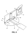
- Fig. 9 shows that one preferable embodiment has a stop member 86 which is connected to the support seat 16 and has two second stops 88.
- the third connection element 22 has an extension portion 90a located corresponding to the two second stops 88.
- One of the second stops 88 of the stop member 86 contacts the extension portion 90a of the third connection element 22, so that the connection between the support seat 16 and the third connection element 22 can be maintained and does not swing.
- the cable management device is firmly and statically supported when in the retracted status as shown in Fig. 3 .
- the weight of the whole cable management device is shared and dynamically supported by the correspondingly varied structure of the cable management device when in extended statuses as shown in Figs. 4-7 . Consequently, the cable management device does not overly sagging when the cable management device carried cables.
Landscapes
- Engineering & Computer Science (AREA)
- Computer Hardware Design (AREA)
- General Engineering & Computer Science (AREA)
- Microelectronics & Electronic Packaging (AREA)
- Seats For Vehicles (AREA)
Abstract
Description
- The present invention relates to a cable management device, and more particularly, to a support device for cable management.
-
U.S Patent No. 7,472,795 B2 to Dubon et al. ,U.S Patent No. 7,654,398 B2 to Bridges et al. ,U.S Patent No. 7,746,667 B1 to Baiza et al. , andU.S Patent No. 7,554,819 B2 ,U.S Patent No. 7,712,615 B2 ,U.S Patent No. 8,231,014 B2 andU.S Patent No. 8,251,321 B2 to Chen et al. disclose conventional support devices for cable management and these support devices are referenced when describing the present invention. - However, these conventional support devices are not convenient when being installed and operated. The present invention intends to provide a support device for cable management and improves the shortcomings of the conventional support devices.
- The present invention relates to a cable management device and comprises a first cable management arm, a second cable management arm, a cable management seat, an extension board, a support seat, a first support member, a second support member, a guide member, a first resilient member and a slide. The cable management seat is pivotably connected between the first and second cable management arms. The extension board is fixed to the cable management seat. The support seat has a support board. A first connection element is connected to the first cable management arm and a second connection element is connected to the second cable management arm. A third connection element is connected to the support seat. The first support member has a first connecting end and a first free end which is located corresponding to the first connecting end. The first support member is pivotably connected to the support seat by the first connecting end. The first support member contacts the support board of the support seat. The second support member has a second connecting end and a second free end which is located corresponding to the second connecting end. The second support member is slidably connected to the first support member. The second support member is extended relative to the first support member to move the second free end away from the first support member. The second free end has a guide member which is extended therefrom and located between the first and second cable management arms. The first resilient member is connected between the first and second support members so as to provide a pull force to the second support member. That is to say, the second support member is pulled by the first resilient member relative to the first support member. A slide is pivotably connected to the extension board and slidably connected to the second support member. The first cable management arm is connected to a stationary first position by the first connection element. The second cable management arm is connected to a changeable second position by the second connection element. The support seat is connected to a stationary third position by the third connection element. When the second connection element of the second cable management arm is moved away from the first connection element of the first cable management arm, the cable management seat slides along the second support member by the slide and moves away from the support seat. The slide contacts the guide member and extends the second support member relative to the first support member so as to swing the first support member relative to the support seat.
- Preferably, the second support member has a block at the second connecting end and the block is located corresponding to the slide, so that the slide slides between the guide member and the block.
- Preferably, the first support member has a first hook and the second support member has a second hook. The first resilient member is connected to the first and second hooks.
- Preferably, the support seat, the third connection element and the first support member are pivotably connected to each other by a pivotal member.
- Preferably, the support board of the support seat extends substantially horizontally and has a round periphery whose center is the same with the center of the pivotal member. A pin is connected to the first support member and the pin slidably contacts the periphery of the support board.
- Preferably, the support board of the support seat has two first stops. A range of the first support member that is pivotable relative to the support seat is restricted between the two first stops.
- Preferably, the extension board has a rib extending downward, and the rib contacts the slide.
- Preferably, the stop member is connected to the support seat and has two second stops. The third connection element has an extension portion located corresponding to the two second stops. One of the two second stops of the stop member contacts the extension portion of the third connection element.
- Preferably, the present invention comprises a first slide assembly which comprises a first stationary rail and a first movable rail which moves longitudinally relative to the first stationary rail. A second slide assembly comprises a second stationary rail and a second movable rail which moves longitudinally relative to the second stationary rail. The first connection element is installed to the first stationary rail and fixedly located at the first position. The second connection element is installed to the first movable rail and located at the second position which is changeable when the first movable rail is moved relative to the first stationary rail. The third connection element is installed to the second stationary rail of the second rail assembly and fixedly located at the third position.
- Alternatively, the present invention provides a cable management system and comprises a first slide assembly comprising a first stationary rail and a first movable rail which moves longitudinally relative to the first stationary rail. A second slide assembly comprises a second stationary rail and a second movable rail which moves longitudinally relative to the second stationary rail. A first cable management arm is connected to the first stationary rail of the first slide assembly. A second cable management arm is connected to the first movable rail of the first slide assembly. A cable management seat is pivotably connected between the first and second cable management arms. A support seat is connected to the second stationary rail of the second slide assembly. A first support member has a first connecting end and a first free end which is located corresponding to the first connecting end. The first connecting end is pivotably connected to the support seat. A second support member has a second connecting end and a second free end which is located corresponding to the second connecting end. The second connecting end is slidably connected to the first support member. The second free end has a guide member which is extended therefrom and located between the first and second cable management arms. A first resilient member is connected between the first and second support members. A slide is pivotably connected to the cable management seat and slidably connected to the second support member. When the first and second slide assemblies are pulled out, the second cable management arm is moved away from the first cable management arm. The slide slides along the second support member and moves away from the support seat. The slide contacts the guide member and extends the second support member relative to the first support member so as to swing the first support member relative to the support seat. When the first and second slide assemblies are retracted, the second cable management arm is retracted relative to the first cable management arm. The second cable management arm contacts the guide member and drives the second support member which moves in response to the first resilient member and relative to the first support member.
- The present invention will become more obvious from the following description when taken in connection with the accompanying drawings which show, for purposes of illustration only, a preferred embodiment in accordance with the present invention.
-
-
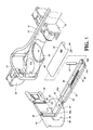
Fig. 1 is an exploded view to show the cable management device of the present invention; -
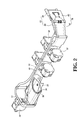
Fig. 2 is a perspective view to show a portion of the cable management device of the present invention; -
Fig. 3 shows that the cable management device of the present invention is at the retracted position; -
Fig. 4 shows that the second connection element of the second cable management arm is moved to a first distance relative to the first connection element of the first cable management arm; -
Fig. 5 shows that the second connection element of the second cable management arm is moved to a second distance relative to the first connection element of the first cable management arm; -
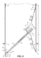
Fig. 6 shows that the second connection element of the second cable management arm is moved to a third distance relative to the first connection element of the first cable management arm; -
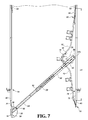
Fig. 7 shows that the second connection element of the second cable management arm is moved to a fourth distance relative to the first connection element of the first cable management arm; -
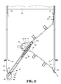
Fig. 8 shows the cable management device of the present invention is retracted, and -
Fig. 9 shows that the stop member contacts the first support member. - Referring to
Figs. 1 and2 , the cable management device of the present invention comprises a firstcable management arm 10, a secondcable management arm 12, acable management seat 14, asupport seat 16, afirst connection element 18, asecond connection element 20, athird connection element 22, afirst support member 24, asecond support member 26, a firstresilient member 28, aslide 30 and multiple cable supports 32. Some of the cable supports 32 are located at the firstcable management arm 10, the secondcable management arm 12 and thecable management seat 14 so that cables (not shown) are put on the cable supports 32. - The
cable management seat 14 is pivotably connected between the first and secondcable management arms cable management seat 14 has anextension board 34. In a preferable embodiment, theextension board 34 is a single member and fixed to the underside of thecable management seat 14. Alternatively, theextension board 34 and thecable management seat 14 are a one-piece part so that theextension board 34 can be deemed as a portion of thecable management seat 14. In a preferable embodiment, theextension board 34 has arib 36 extending downward therefrom. - The
support seat 16 has asupport board 38. In a preferable embodiment, thesupport board 38 of thesupport seat 16 extends substantially horizontally and has a round periphery. Preferably, the periphery of thesupport board 38 that points thefirst support member 24 is generally formed as a semi-circular about thepivotal member 48. Thesupport board 38 of thesupport seat 16 has two first stops 39. - The
first connection element 18 is connected to the firstcable management arm 10 and has a first engagingmember 40 and afirst connection member 42 pivotably connected to the first engagingmember 40. In a preferable embodiment, thefirst connection member 42 is pivotably connected to the firstcable management arm 10. - The
second connection element 20 is connected to the secondcable management arm 12 and has a second engagingmember 44 and asecond connection member 46 pivotably connected to the second engagingmember 44. In a preferable embodiment, thesecond connection member 46 is pivotably connected to the secondcable management arm 12. - The
third connection element 22 is pivotably connected to thesupport seat 16 by apivotal member 48. - The
first support member 24 has a first connectingend 50a and a firstfree end 50b which is located corresponding to the first connectingend 50a. In a preferable embodiment, the first connectingend 50a of thefirst support member 24 is pivotably connected to thesupport board 38 of thesupport seat 16 by thepivotal member 48. Thefirst support member 24 contacts thesupport board 38 of thesupport seat 16 and is located between the twofirst stops 39 so that the range of thefirst support member 24 that is pivotable relative to thesupport seat 16 is restricted between the two first stops 39. In a preferable embodiment, apin 52 is connected to thefirst support member 24, and the center of the periphery of thesupport board 38 is the same with the center of thepivotal member 48. When thefirst support member 24 swings relative to thesupport seat 16, thepin 52 slidably contacts the periphery of thesupport board 38. Thefirst support member 24 has apath 54 and afirst hook 56, wherein thepath 54 is a recessed area extending along thefirst support member 24, and thefirst hook 56 extends from the wall of thepath 54. - The
second support member 26 has a secondconnecting end 57a and a secondfree end 57b which is located corresponding to the second connectingend 57a. Thesecond support member 26 is slidably connected to thefirst support member 24, such as slidably mounted to thefirst support member 24 so that thesecond support member 26 is extendable and retractable relative to thefirst support member 24. When thesecond support member 26 is extended relative to thefirst support member 24, the secondfree end 57b is moved away from thefirst support member 24. The secondfree end 57b has aguide member 58 which is extended therefrom and located between the first and secondcable management arms Fig. 3 . In a preferable embodiment, thesecond support member 26 has a second hook 60 extending toward thepath 54 of thefirst support member 24. The secondconnecting end 57a of thesecond support member 26 has ablock 62, and theblock 62 is located corresponding to theslide 30, so that theslide 30 slides between theguide member 58 and theblock 62. - The first
resilient member 28 is connected between the first andsecond hooks 56, 60 of thesupport members second support member 26 is pulled by the firstresilient member 28 to thefirst support member 24 when thesecond support member 26 is extended relative to thefirst support member 24. In other words, thesecond support member 26 is able to respond the force from the firstresilient member 28 and move relative to thefirst support member 24. For example, thesecond support member 26 is correspondingly retracted to thefirst support member 24 by the force of the firstresilient member 28 from an extended status. - The
slide 30 is pivotably connected to the underside of theextension board 34 by apivot 64, and slidable betweenguide member 58 of thesecond support member 26 and theblock 62 as shown inFig. 3 . It is noted that theextension board 34 is deemed as a portion of thecable management seat 14, so that theslide 30 pivotably connected to thecable management seat 14 can be considered as the same with theslide 30 pivotably connected to theextention board 34. In a preferable embodiment, thepivot 64 extends through theslide 30 and theextension board 34, and is cooperated with the contact between theslide 30 and therib 36 of theextension board 34, to let theslide 30 and theextension board 34 be snugly in contact with each other in vertical direction and hence to prevent the first and secondcable management arms slide 30 moves to the secondfree end 57b of thesecond support member 26, theslide 30 contacts theguide member 58 so as to drive thesecond support member 26 to extend relative to thefirst support member 24. -
Fig. 3 shows the cable management device is connected to thefirst slide assembly 72 and thesecond slide assembly 74. Thefirst slide assembly 72 comprises a firststationary rail 76 and a firstmovable rail 78 which moves longitudinally relative to the firststationary rail 76. Thesecond slide assembly 74 comprises a secondstationary rail 80 and a secondmovable rail 82 which moves longitudinally relative to the secondstationary rail 80. Aservo equipment 84 is connected to the firstmovable rail 78 and the secondmovable rail 82 of the first andsecond slide assemblies servo equipment 84 is positioned by the first and secondcable management arms cable management seat 14. The firstcable management arm 10 is connected to the firststationary rail 76 of thefirst slide assembly 72 by the first engagingmember 40 of thefirst connection element 18 so as to position one end of the firstcable management arm 10 at a first position. The secondcable management arm 12 is connected to the firstmovable rail 78 of thefirst slide assembly 72 by the second engagingmember 44 of thesecond connection element 20 so as to position one end of the secondcable management arm 12 at a second position. The second position is changeable when the firstmovable rail 78 of thefirst slide assembly 72 moves relative to the firststationary rail 76. Thesupport seat 16 is connected to the secondstationary rail 80 of thesecond slide assembly 74 by thethird connection element 22 so as to position at a third position. - As shown in
Fig. 3 , when the first andsecond slide assemblies cable management arm 12 moves toward and close to the firstcable management arm 10 to form a long cantilever beam so that the center of weight of the whole cable management device is located toward thecable management seat 14. Thesecond support member 26 is retracted to thefirst support member 24, and thefirst support member 24 contacts thesupport board 38 of thesupport seat 16. Thecable management seat 14 is located adjacent to thesupport seat 16 by theslide 30 mounted to thesecond support member 26. Therefore, under the retracted status that the secondcable management arm 12 located close to the firstcable management arm 10, thesupport seat 16 provides efficient support to the cable management device. -
Fig. 4 shows that the first and secondmovable rails second slide assemblies second connection element 20 of the secondcable management arm 12 moves a first distance L1 relative to thefirst connection element 18 of the firstcable management arm 10. Thesecond support member 26 is not yet extended relative to thefirst support member 24. Thecable management seat 14 and theextension board 34 move straightly along thesecond support member 26 by theslide 30. Thecable management seat 14 moves a longitudinal displacement along with the movement of the secondcable management arm 12. Therefore, thecable management seat 14 drives thefirst support member 24 to swing relative to thesupport seat 16 by theslide 30 and thesecond support member 26. The swinging of thefirst support member 24 makes theguide member 58 contact the secondcable management arm 12, so that the secondfree end 57b of thesecond support member 26 is maintained between the first and secondcable management arms slide 30 is pivotable relative to theextension board 34. Under the present status, the center of weight of the whole cable management device is transferred gradually from thesupport seat 16 to thesecond support member 26, and thesupport seat 16 and thesecond support member 26, including thefirst support member 24, together provide an efficient support to the cable management device. -
Fig. 5 shows that when thesecond connection element 20 of the secondcable management arm 12 continuously moves to the second distance L2 relative to thefirst connection element 18 of the firstcable management arm 10. Thecable management seat 14 and theextension board 34 move along thesecond support member 26 to theguide member 58 by theslide 30. When theslide 30 contacts theguide member 58, theslide 30 drives thesecond support member 26 to extend relative to thefirst support member 24, and the firstresilient member 28 is stretched by thesecond support member 26 to generate a force which is able to pull thesecond support member 26 back. Because thecable management seat 14 is moves away from thesupport seat 16 and toward thefirst slide assembly 72, when thecable management seat 14 is gradually moves close to the center of the transverse distance between the first andsecond slide assemblies support seat 16 to the first and secondcable management arms second support members support seat 16 and assist to support the weight that the first and secondcable management arms second support members cable management arms -
Fig. 6 shows that thesecond connection element 20 of the secondcable management arm 12 continuously moves to the second distance L3 relative to thefirst connection element 18 of the firstcable management arm 10. Thecable management seat 14 and theextension board 34 carried by theslide 30 extend thesecond support member 26 away from thefirst support member 24, and the firstresilient member 28 continuously provides a pull force to thesecond support member 26. Thecable management seat 14 moves over the center of the transverse distance between the first andsecond slide assemblies first slide assembly 72. Therefore, the most of the weight of the cable management device will be transferred to and supported by the first and secondcable management arms second support members -
Fig. 7 shows that thesecond connection element 20 of the secondcable management arm 12 moves to the complete extended fourth distance L4 relative to thefirst connection element 18 of the firstcable management arm 10. Thecable management seat 14 and theextension board 34 extend completely relative to thefirst support member 24 by theslide 30 driving thesecond support member 26. Thefirst support member 24 continuously swings relative to thesupport seat 16, and the firstresilient member 28 continuously apply a pull force to thesecond support member 26. Under this status, thecable management seat 14 is located very close to thefirst slide assembly 72, so that the most of the weight of the cable management device is supported by the first and secondcable management arms second support members cable management seat 14 and do not support the weight of the cable management device. - It is noted that during the retracting process of the cable management device, the
second support member 26 responds the force of the firstresilient member 28 so as to be automatically pulled back relative to thefirst support member 24. In other words, when theslide 30 moves along thesecond support member 26 and toward thesupport seat 16, thesecond support member 26 is automatically retracted relative to thefirst support member 24, and theguide member 58 contacts theslide 30, so that the movement of theslide 30 and thesecond support member 26 are simultaneously proceeded. On the other hand, as shown inFig. 8 , when the second andfirst support members slide 30 continuously slides on thesecond support member 26, the secondcable management arm 12 directly contacts theguide member 58 of the secondfree end 57b of thesecond support member 26, so that the operation of the overall mechanism of the cable management device is smooth and thefirst support member 24 swings back to the pre-set retracted position. Besides, when theguide member 58 of thesecond support member 26 is in contact with the secondcable management arm 12, the first stops 39 of thesupport seat 16 contact thefirst support member 24 to restrict the first andsecond support members second slide assembly 74 so as not to affect the approach of the secondcable management arm 12 toward the firstcable management arm 10. -
Fig. 9 shows that one preferable embodiment has astop member 86 which is connected to thesupport seat 16 and has two second stops 88. Thethird connection element 22 has anextension portion 90a located corresponding to the two second stops 88. One of the second stops 88 of thestop member 86 contacts theextension portion 90a of thethird connection element 22, so that the connection between thesupport seat 16 and thethird connection element 22 can be maintained and does not swing. - The cable management device is firmly and statically supported when in the retracted status as shown in
Fig. 3 . The weight of the whole cable management device is shared and dynamically supported by the correspondingly varied structure of the cable management device when in extended statuses as shown inFigs. 4-7 . Consequently, the cable management device does not overly sagging when the cable management device carried cables. - While we have shown and described the embodiment in accordance with the present invention, it should be clear to those skilled in the art that further embodiments may be made without departing from the scope of the present invention.
Claims (10)
- A cable management device comprising: a first cable management arm (10); a second cable management arm (12); a cable management seat (14) pivotably connected between the first and second cable management arms (10, 12); an extension board (34) fixed to the cable management seat (14); a support seat (16) having a support board (38); a first connection element (18) connected to the first cable management arm (10); a second connection element (20) connected to the second cable management arm (12); a third connection element (22) connected to the support seat (16); characterized in that a first support member (24) has a first connecting end (50a) and a first free end (50b) which is located corresponding to the first connecting end (50a), the first support member (24) is pivotably connected to the support seat (16) by the first connecting end (50a), the first support member (24) contacts the support board (38) of the support seat (16); a second support member (26) has a second connecting end (57a) and a second free end (57b) which is located corresponding to the second connecting end (57a), the second support member (26) is slidably connected to the first support member (24) so as to extend relative to the first support member (24) to move the second free end (57b) away from the first support member (24), the second free end (57b) has a guide member (58) which is extended therefrom and located between the first and second cable management arms (10, 12); a first resilient member (28) is connected between the first and second support members (24, 26) so as to provide a pull force to the second support member (26); and a slide (30) is pivotably connected to the extension board (34) and slidably connected to the second support member (26); wherein, the first cable management arm (10) is connected to a stationary first position by the first connection element (18), the second cable management arm (12) is connected to a changeable second position by the second connection element (20), the support seat (16) is connected to a stationary third position by the third connection element (22), when the second connection element (20) of the second cable management arm (12) is moved away from the first connection element (18) of the first cable management arm (10), the cable management seat (14) slides along the second support member (26) by the slide (30) and moves away from the support seat (16), the slide (30) contacts the guide member (58) and extends the second support member (26) relative to the first support member (24) so as to swing the first support member (24) relative to the support seat (16).
- The device as claimed in claim 1, wherein the second support member (26) has a block (62) at the second connecting end (57a), and the block (62) is located corresponding to the slide (30), so that the slide (30) slides between the guide member (58) and the block (62).
- The device as claimed in claim 1 or 2, wherein the first support member (24) has a first hook (56) and the second support member (26) has a second hook (60), the first resilient member (28) is connected to the first and second hooks (56, 60).
- The device as claimed in any one of claims 1-3, wherein the support seat (16), the third connection element (22) and the first support member (24) are pivotably connected to each other by a pivotal member (48).
- The device as claimed in claim 4, wherein the support board (38) of the support seat (16) extends substantially horizontally and has a round periphery whose center of circle is the same with the center of the pivotal member (48), a pin (52) connected to the first support member (24), and the pin (52) slidably contacts the periphery of the support board (38).
- The device as claimed in claim 4 or 5, wherein the support board (38) of the support seat (16) has two first stops (39), a range of the first support member (24) that is pivotable relative to the support seat (16) is restricted between the two first stops (39).
- The device as claimed in any one of claims 1-6, wherein the extension board (34) has a rib (36) extending downward, and the rib (36) contacts the slide (30).
- The device as claimed in any one of claims 1-7, further comprising a stop member (86) connected to the support seat (16) and having two second stops (88), wherein the third connection element (22) has an extension portion (90a) located corresponding to the two second stops (88), one of the two second stops (88) of the stop member (86) contacts the extension portion (90a) of the third connection element (22).
- The device as claimed in any one of claims 1-8 further comprising a first slide assembly (72) which comprises a first stationary rail (76) and a first movable rail (78) which moves longitudinally relative to the first stationary rail (76), a second slide assembly (74) comprising a second stationary rail (80) and a second movable rail (82) which moves longitudinally relative to the second stationary rail (80), wherein the first connection element (18) is installed to the first stationary rail (76) and fixedly located at the first position, the second connection element (20) is installed to the first movable rail (78) and located at the second position which is changeable when the first movable rail (78) is moved relative to the first stationary rail (76), the third connection element (22) is installed to the second stationary rail (80) of the second rail assembly (74) and fixedly located at the third position.
- The device as claimed in any one of claims 1-9, wherein when the second connection element (20) of the second cable management arm (12) is retraced toward the first connection element (18) of the first cable management arm (10), the second cable management arm (12) is retracted relative to the first cable management arm (10), the second cable management arm (12) contacts the guide member (58) and drives the second support member (26) which moves in response to the first resilient member (28) and relative to the first support member (24).
Priority Applications (1)
| Application Number | Priority Date | Filing Date | Title |
|---|---|---|---|
| EP13163127.7A EP2790478B1 (en) | 2013-04-10 | 2013-04-10 | Cable management device |
Applications Claiming Priority (1)
| Application Number | Priority Date | Filing Date | Title |
|---|---|---|---|
| EP13163127.7A EP2790478B1 (en) | 2013-04-10 | 2013-04-10 | Cable management device |
Publications (2)
| Publication Number | Publication Date |
|---|---|
| EP2790478A1 true EP2790478A1 (en) | 2014-10-15 |
| EP2790478B1 EP2790478B1 (en) | 2016-11-09 |
Family
ID=48049891
Family Applications (1)
| Application Number | Title | Priority Date | Filing Date |
|---|---|---|---|
| EP13163127.7A Active EP2790478B1 (en) | 2013-04-10 | 2013-04-10 | Cable management device |
Country Status (1)
| Country | Link |
|---|---|
| EP (1) | EP2790478B1 (en) |
Citations (7)
| Publication number | Priority date | Publication date | Assignee | Title |
|---|---|---|---|---|
| US20050145582A1 (en) * | 2003-12-05 | 2005-07-07 | William Dubon | Anti-sag management assembly |
| US20060113433A1 (en) * | 2004-10-15 | 2006-06-01 | Ken-Ching Chen | Cable management arm assembly |
| US20070017883A1 (en) * | 2005-07-19 | 2007-01-25 | International Business Machines Corporation | Cable management system with adjustable length arm |
| US20090014601A1 (en) * | 2007-07-11 | 2009-01-15 | King Slide Works Co., Ltd. | Cable management arm connection system |
| US20090078834A1 (en) * | 2004-10-15 | 2009-03-26 | King Slide Works Co., Ltd. | Support slide assembly for cable management arm |
| US7746667B1 (en) | 2007-12-05 | 2010-06-29 | Central Industrial Supply Company | Telescoping support crossbar for a cable management arm |
| US20100193646A1 (en) * | 2008-09-03 | 2010-08-05 | King Slide Works Co., Ltd. | Support slide assembly for a cable management arm |
-
2013
- 2013-04-10 EP EP13163127.7A patent/EP2790478B1/en active Active
Patent Citations (13)
| Publication number | Priority date | Publication date | Assignee | Title |
|---|---|---|---|---|
| US7472795B2 (en) | 2003-12-05 | 2009-01-06 | Pentair Electronic Packaging Company | Anti-sag management assembly |
| US20050145582A1 (en) * | 2003-12-05 | 2005-07-07 | William Dubon | Anti-sag management assembly |
| US7554819B2 (en) | 2004-10-15 | 2009-06-30 | King Slide Works Co., Ltd. | Cable management arm assembly |
| US20090078834A1 (en) * | 2004-10-15 | 2009-03-26 | King Slide Works Co., Ltd. | Support slide assembly for cable management arm |
| US20060113433A1 (en) * | 2004-10-15 | 2006-06-01 | Ken-Ching Chen | Cable management arm assembly |
| US7712615B2 (en) | 2004-10-15 | 2010-05-11 | King Slide Works Co., Ltd. | Support slide assembly for cable management arm |
| US20070017883A1 (en) * | 2005-07-19 | 2007-01-25 | International Business Machines Corporation | Cable management system with adjustable length arm |
| US7654398B2 (en) | 2005-07-19 | 2010-02-02 | International Business Machines Corporation | Cable management system with adjustable length arm |
| US20090014601A1 (en) * | 2007-07-11 | 2009-01-15 | King Slide Works Co., Ltd. | Cable management arm connection system |
| US8251321B2 (en) | 2007-07-11 | 2012-08-28 | King Slide Works Co., Ltd. | Cable management arm connection system |
| US7746667B1 (en) | 2007-12-05 | 2010-06-29 | Central Industrial Supply Company | Telescoping support crossbar for a cable management arm |
| US20100193646A1 (en) * | 2008-09-03 | 2010-08-05 | King Slide Works Co., Ltd. | Support slide assembly for a cable management arm |
| US8231014B2 (en) | 2008-09-03 | 2012-07-31 | King Slide Works Co., Ltd. | Support slide assembly for a cable management arm |
Also Published As
| Publication number | Publication date |
|---|---|
| EP2790478B1 (en) | 2016-11-09 |
Similar Documents
| Publication | Publication Date | Title |
|---|---|---|
| US9072194B2 (en) | Cable management device | |
| US9072190B2 (en) | Cable management arm | |
| US8231014B2 (en) | Support slide assembly for a cable management arm | |
| US9867311B2 (en) | Server cable management structure | |
| EP3291659A1 (en) | Cable management device | |
| EP3143901B1 (en) | Slide rail assembly | |
| US20160039346A1 (en) | Vehicle step apparatus and extending and retracting device thereof | |
| US20190053396A1 (en) | Cable Management Device and Connecting Assembly for Rack System | |
| US20090166478A1 (en) | Apparatus for Controlling Cable of Robot | |
| CN104000405B (en) | Support structure of bracket and slide rail | |
| US20130299658A1 (en) | Support Apparatus for Suspending a Display | |
| EP2433863A3 (en) | Slat support assembly | |
| US9635942B2 (en) | Slide rail assembly | |
| EP3282713A1 (en) | Slide rail assembly and cable management device thereof | |
| US20210195784A1 (en) | Support assembly and cable management kit | |
| JP2011255495A (en) | Line guidance device with reset unit, and robot with the same | |
| EP3291660A1 (en) | Slide rail assembly and cable management device thereof | |
| EP3076774B1 (en) | Slide rail assembly | |
| CN105530793A (en) | Cable management support device and installation components | |
| WO2015165144A1 (en) | Switch structure | |
| JP3189902U (en) | Slide rail kit | |
| TW201434224A (en) | Cable management arm | |
| US20160229360A1 (en) | Wire routing structure | |
| EP2790478B1 (en) | Cable management device | |
| EP2744314B1 (en) | Cable Management Arm |
Legal Events
| Date | Code | Title | Description |
|---|---|---|---|
| PUAI | Public reference made under article 153(3) epc to a published international application that has entered the european phase |
Free format text: ORIGINAL CODE: 0009012 |
|
| 17P | Request for examination filed |
Effective date: 20131002 |
|
| AK | Designated contracting states |
Kind code of ref document: A1 Designated state(s): AL AT BE BG CH CY CZ DE DK EE ES FI FR GB GR HR HU IE IS IT LI LT LU LV MC MK MT NL NO PL PT RO RS SE SI SK SM TR |
|
| AX | Request for extension of the european patent |
Extension state: BA ME |
|
| GRAP | Despatch of communication of intention to grant a patent |
Free format text: ORIGINAL CODE: EPIDOSNIGR1 |
|
| INTG | Intention to grant announced |
Effective date: 20160602 |
|
| GRAS | Grant fee paid |
Free format text: ORIGINAL CODE: EPIDOSNIGR3 |
|
| GRAA | (expected) grant |
Free format text: ORIGINAL CODE: 0009210 |
|
| AK | Designated contracting states |
Kind code of ref document: B1 Designated state(s): AL AT BE BG CH CY CZ DE DK EE ES FI FR GB GR HR HU IE IS IT LI LT LU LV MC MK MT NL NO PL PT RO RS SE SI SK SM TR |
|
| REG | Reference to a national code |
Ref country code: GB Ref legal event code: FG4D |
|
| REG | Reference to a national code |
Ref country code: AT Ref legal event code: REF Ref document number: 844968 Country of ref document: AT Kind code of ref document: T Effective date: 20161115 Ref country code: CH Ref legal event code: EP |
|
| REG | Reference to a national code |
Ref country code: IE Ref legal event code: FG4D |
|
| REG | Reference to a national code |
Ref country code: DE Ref legal event code: R096 Ref document number: 602013013711 Country of ref document: DE |
|
| REG | Reference to a national code |
Ref country code: NL Ref legal event code: FP |
|
| PG25 | Lapsed in a contracting state [announced via postgrant information from national office to epo] |
Ref country code: LV Free format text: LAPSE BECAUSE OF FAILURE TO SUBMIT A TRANSLATION OF THE DESCRIPTION OR TO PAY THE FEE WITHIN THE PRESCRIBED TIME-LIMIT Effective date: 20161109 |
|
| REG | Reference to a national code |
Ref country code: LT Ref legal event code: MG4D |
|
| REG | Reference to a national code |
Ref country code: AT Ref legal event code: MK05 Ref document number: 844968 Country of ref document: AT Kind code of ref document: T Effective date: 20161109 |
|
| PG25 | Lapsed in a contracting state [announced via postgrant information from national office to epo] |
Ref country code: NO Free format text: LAPSE BECAUSE OF FAILURE TO SUBMIT A TRANSLATION OF THE DESCRIPTION OR TO PAY THE FEE WITHIN THE PRESCRIBED TIME-LIMIT Effective date: 20170209 Ref country code: SE Free format text: LAPSE BECAUSE OF FAILURE TO SUBMIT A TRANSLATION OF THE DESCRIPTION OR TO PAY THE FEE WITHIN THE PRESCRIBED TIME-LIMIT Effective date: 20161109 Ref country code: LT Free format text: LAPSE BECAUSE OF FAILURE TO SUBMIT A TRANSLATION OF THE DESCRIPTION OR TO PAY THE FEE WITHIN THE PRESCRIBED TIME-LIMIT Effective date: 20161109 |
|
| PG25 | Lapsed in a contracting state [announced via postgrant information from national office to epo] |
Ref country code: FI Free format text: LAPSE BECAUSE OF FAILURE TO SUBMIT A TRANSLATION OF THE DESCRIPTION OR TO PAY THE FEE WITHIN THE PRESCRIBED TIME-LIMIT Effective date: 20161109 Ref country code: RS Free format text: LAPSE BECAUSE OF FAILURE TO SUBMIT A TRANSLATION OF THE DESCRIPTION OR TO PAY THE FEE WITHIN THE PRESCRIBED TIME-LIMIT Effective date: 20161109 Ref country code: PT Free format text: LAPSE BECAUSE OF FAILURE TO SUBMIT A TRANSLATION OF THE DESCRIPTION OR TO PAY THE FEE WITHIN THE PRESCRIBED TIME-LIMIT Effective date: 20170309 Ref country code: PL Free format text: LAPSE BECAUSE OF FAILURE TO SUBMIT A TRANSLATION OF THE DESCRIPTION OR TO PAY THE FEE WITHIN THE PRESCRIBED TIME-LIMIT Effective date: 20161109 Ref country code: AT Free format text: LAPSE BECAUSE OF FAILURE TO SUBMIT A TRANSLATION OF THE DESCRIPTION OR TO PAY THE FEE WITHIN THE PRESCRIBED TIME-LIMIT Effective date: 20161109 Ref country code: ES Free format text: LAPSE BECAUSE OF FAILURE TO SUBMIT A TRANSLATION OF THE DESCRIPTION OR TO PAY THE FEE WITHIN THE PRESCRIBED TIME-LIMIT Effective date: 20161109 Ref country code: IS Free format text: LAPSE BECAUSE OF FAILURE TO SUBMIT A TRANSLATION OF THE DESCRIPTION OR TO PAY THE FEE WITHIN THE PRESCRIBED TIME-LIMIT Effective date: 20170309 Ref country code: HR Free format text: LAPSE BECAUSE OF FAILURE TO SUBMIT A TRANSLATION OF THE DESCRIPTION OR TO PAY THE FEE WITHIN THE PRESCRIBED TIME-LIMIT Effective date: 20161109 |
|
| PG25 | Lapsed in a contracting state [announced via postgrant information from national office to epo] |
Ref country code: CZ Free format text: LAPSE BECAUSE OF FAILURE TO SUBMIT A TRANSLATION OF THE DESCRIPTION OR TO PAY THE FEE WITHIN THE PRESCRIBED TIME-LIMIT Effective date: 20161109 Ref country code: DK Free format text: LAPSE BECAUSE OF FAILURE TO SUBMIT A TRANSLATION OF THE DESCRIPTION OR TO PAY THE FEE WITHIN THE PRESCRIBED TIME-LIMIT Effective date: 20161109 Ref country code: RO Free format text: LAPSE BECAUSE OF FAILURE TO SUBMIT A TRANSLATION OF THE DESCRIPTION OR TO PAY THE FEE WITHIN THE PRESCRIBED TIME-LIMIT Effective date: 20161109 Ref country code: SK Free format text: LAPSE BECAUSE OF FAILURE TO SUBMIT A TRANSLATION OF THE DESCRIPTION OR TO PAY THE FEE WITHIN THE PRESCRIBED TIME-LIMIT Effective date: 20161109 Ref country code: EE Free format text: LAPSE BECAUSE OF FAILURE TO SUBMIT A TRANSLATION OF THE DESCRIPTION OR TO PAY THE FEE WITHIN THE PRESCRIBED TIME-LIMIT Effective date: 20161109 |
|
| REG | Reference to a national code |
Ref country code: DE Ref legal event code: R097 Ref document number: 602013013711 Country of ref document: DE |
|
| PG25 | Lapsed in a contracting state [announced via postgrant information from national office to epo] |
Ref country code: BG Free format text: LAPSE BECAUSE OF FAILURE TO SUBMIT A TRANSLATION OF THE DESCRIPTION OR TO PAY THE FEE WITHIN THE PRESCRIBED TIME-LIMIT Effective date: 20170209 Ref country code: IT Free format text: LAPSE BECAUSE OF FAILURE TO SUBMIT A TRANSLATION OF THE DESCRIPTION OR TO PAY THE FEE WITHIN THE PRESCRIBED TIME-LIMIT Effective date: 20161109 Ref country code: SM Free format text: LAPSE BECAUSE OF FAILURE TO SUBMIT A TRANSLATION OF THE DESCRIPTION OR TO PAY THE FEE WITHIN THE PRESCRIBED TIME-LIMIT Effective date: 20161109 Ref country code: BE Free format text: LAPSE BECAUSE OF FAILURE TO SUBMIT A TRANSLATION OF THE DESCRIPTION OR TO PAY THE FEE WITHIN THE PRESCRIBED TIME-LIMIT Effective date: 20161109 |
|
| PLBE | No opposition filed within time limit |
Free format text: ORIGINAL CODE: 0009261 |
|
| STAA | Information on the status of an ep patent application or granted ep patent |
Free format text: STATUS: NO OPPOSITION FILED WITHIN TIME LIMIT |
|
| 26N | No opposition filed |
Effective date: 20170810 |
|
| PG25 | Lapsed in a contracting state [announced via postgrant information from national office to epo] |
Ref country code: SI Free format text: LAPSE BECAUSE OF FAILURE TO SUBMIT A TRANSLATION OF THE DESCRIPTION OR TO PAY THE FEE WITHIN THE PRESCRIBED TIME-LIMIT Effective date: 20161109 |
|
| REG | Reference to a national code |
Ref country code: CH Ref legal event code: PL |
|
| REG | Reference to a national code |
Ref country code: IE Ref legal event code: MM4A |
|
| REG | Reference to a national code |
Ref country code: FR Ref legal event code: ST Effective date: 20171229 |
|
| PG25 | Lapsed in a contracting state [announced via postgrant information from national office to epo] |
Ref country code: FR Free format text: LAPSE BECAUSE OF NON-PAYMENT OF DUE FEES Effective date: 20170502 Ref country code: MC Free format text: LAPSE BECAUSE OF FAILURE TO SUBMIT A TRANSLATION OF THE DESCRIPTION OR TO PAY THE FEE WITHIN THE PRESCRIBED TIME-LIMIT Effective date: 20161109 |
|
| PG25 | Lapsed in a contracting state [announced via postgrant information from national office to epo] |
Ref country code: CH Free format text: LAPSE BECAUSE OF NON-PAYMENT OF DUE FEES Effective date: 20170430 Ref country code: LU Free format text: LAPSE BECAUSE OF NON-PAYMENT OF DUE FEES Effective date: 20170410 Ref country code: LI Free format text: LAPSE BECAUSE OF NON-PAYMENT OF DUE FEES Effective date: 20170430 |
|
| PG25 | Lapsed in a contracting state [announced via postgrant information from national office to epo] |
Ref country code: IE Free format text: LAPSE BECAUSE OF NON-PAYMENT OF DUE FEES Effective date: 20170410 |
|
| PG25 | Lapsed in a contracting state [announced via postgrant information from national office to epo] |
Ref country code: MT Free format text: LAPSE BECAUSE OF NON-PAYMENT OF DUE FEES Effective date: 20170410 |
|
| PG25 | Lapsed in a contracting state [announced via postgrant information from national office to epo] |
Ref country code: HU Free format text: LAPSE BECAUSE OF FAILURE TO SUBMIT A TRANSLATION OF THE DESCRIPTION OR TO PAY THE FEE WITHIN THE PRESCRIBED TIME-LIMIT; INVALID AB INITIO Effective date: 20130410 |
|
| PG25 | Lapsed in a contracting state [announced via postgrant information from national office to epo] |
Ref country code: CY Free format text: LAPSE BECAUSE OF FAILURE TO SUBMIT A TRANSLATION OF THE DESCRIPTION OR TO PAY THE FEE WITHIN THE PRESCRIBED TIME-LIMIT Effective date: 20161109 |
|
| PG25 | Lapsed in a contracting state [announced via postgrant information from national office to epo] |
Ref country code: MK Free format text: LAPSE BECAUSE OF FAILURE TO SUBMIT A TRANSLATION OF THE DESCRIPTION OR TO PAY THE FEE WITHIN THE PRESCRIBED TIME-LIMIT Effective date: 20161109 |
|
| PG25 | Lapsed in a contracting state [announced via postgrant information from national office to epo] |
Ref country code: TR Free format text: LAPSE BECAUSE OF FAILURE TO SUBMIT A TRANSLATION OF THE DESCRIPTION OR TO PAY THE FEE WITHIN THE PRESCRIBED TIME-LIMIT Effective date: 20161109 |
|
| PG25 | Lapsed in a contracting state [announced via postgrant information from national office to epo] |
Ref country code: GR Free format text: LAPSE BECAUSE OF FAILURE TO SUBMIT A TRANSLATION OF THE DESCRIPTION OR TO PAY THE FEE WITHIN THE PRESCRIBED TIME-LIMIT Effective date: 20161109 |
|
| PG25 | Lapsed in a contracting state [announced via postgrant information from national office to epo] |
Ref country code: AL Free format text: LAPSE BECAUSE OF FAILURE TO SUBMIT A TRANSLATION OF THE DESCRIPTION OR TO PAY THE FEE WITHIN THE PRESCRIBED TIME-LIMIT Effective date: 20161109 |
|
| PGFP | Annual fee paid to national office [announced via postgrant information from national office to epo] |
Ref country code: DE Payment date: 20250210 Year of fee payment: 13 |
|
| PGFP | Annual fee paid to national office [announced via postgrant information from national office to epo] |
Ref country code: NL Payment date: 20260211 Year of fee payment: 14 |
|
| PGFP | Annual fee paid to national office [announced via postgrant information from national office to epo] |
Ref country code: GB Payment date: 20260209 Year of fee payment: 14 |