EP2790410A1 - Signalling warp maps using a high efficiency video coding (HEVC) extension for 3D video coding - Google Patents
Signalling warp maps using a high efficiency video coding (HEVC) extension for 3D video coding Download PDFInfo
- Publication number
- EP2790410A1 EP2790410A1 EP20140164611 EP14164611A EP2790410A1 EP 2790410 A1 EP2790410 A1 EP 2790410A1 EP 20140164611 EP20140164611 EP 20140164611 EP 14164611 A EP14164611 A EP 14164611A EP 2790410 A1 EP2790410 A1 EP 2790410A1
- Authority
- EP
- European Patent Office
- Prior art keywords
- message
- computer
- depth
- bitstream
- video coding
- Prior art date
- Legal status (The legal status is an assumption and is not a legal conclusion. Google has not performed a legal analysis and makes no representation as to the accuracy of the status listed.)
- Granted
Links
Images



Classifications
-
- H—ELECTRICITY
- H04—ELECTRIC COMMUNICATION TECHNIQUE
- H04N—PICTORIAL COMMUNICATION, e.g. TELEVISION
- H04N13/00—Stereoscopic video systems; Multi-view video systems; Details thereof
- H04N13/10—Processing, recording or transmission of stereoscopic or multi-view image signals
- H04N13/106—Processing image signals
- H04N13/161—Encoding, multiplexing or demultiplexing different image signal components
-
- H—ELECTRICITY
- H04—ELECTRIC COMMUNICATION TECHNIQUE
- H04N—PICTORIAL COMMUNICATION, e.g. TELEVISION
- H04N13/00—Stereoscopic video systems; Multi-view video systems; Details thereof
- H04N13/20—Image signal generators
- H04N13/271—Image signal generators wherein the generated image signals comprise depth maps or disparity maps
-
- H—ELECTRICITY
- H04—ELECTRIC COMMUNICATION TECHNIQUE
- H04N—PICTORIAL COMMUNICATION, e.g. TELEVISION
- H04N19/00—Methods or arrangements for coding, decoding, compressing or decompressing digital video signals
- H04N19/50—Methods or arrangements for coding, decoding, compressing or decompressing digital video signals using predictive coding
- H04N19/597—Methods or arrangements for coding, decoding, compressing or decompressing digital video signals using predictive coding specially adapted for multi-view video sequence encoding
-
- G—PHYSICS
- G06—COMPUTING OR CALCULATING; COUNTING
- G06T—IMAGE DATA PROCESSING OR GENERATION, IN GENERAL
- G06T3/00—Geometric image transformations in the plane of the image
- G06T3/18—Image warping, e.g. rearranging pixels individually
-
- H—ELECTRICITY
- H04—ELECTRIC COMMUNICATION TECHNIQUE
- H04N—PICTORIAL COMMUNICATION, e.g. TELEVISION
- H04N13/00—Stereoscopic video systems; Multi-view video systems; Details thereof
- H04N13/10—Processing, recording or transmission of stereoscopic or multi-view image signals
- H04N13/106—Processing image signals
- H04N13/172—Processing image signals image signals comprising non-image signal components, e.g. headers or format information
- H04N13/178—Metadata, e.g. disparity information
-
- H—ELECTRICITY
- H04—ELECTRIC COMMUNICATION TECHNIQUE
- H04N—PICTORIAL COMMUNICATION, e.g. TELEVISION
- H04N13/00—Stereoscopic video systems; Multi-view video systems; Details thereof
- H04N13/20—Image signal generators
- H04N13/261—Image signal generators with monoscopic-to-stereoscopic image conversion
-
- H—ELECTRICITY
- H04—ELECTRIC COMMUNICATION TECHNIQUE
- H04N—PICTORIAL COMMUNICATION, e.g. TELEVISION
- H04N19/00—Methods or arrangements for coding, decoding, compressing or decompressing digital video signals
- H04N19/50—Methods or arrangements for coding, decoding, compressing or decompressing digital video signals using predictive coding
- H04N19/503—Methods or arrangements for coding, decoding, compressing or decompressing digital video signals using predictive coding involving temporal prediction
- H04N19/51—Motion estimation or motion compensation
- H04N19/537—Motion estimation other than block-based
- H04N19/54—Motion estimation other than block-based using feature points or meshes
-
- H—ELECTRICITY
- H04—ELECTRIC COMMUNICATION TECHNIQUE
- H04N—PICTORIAL COMMUNICATION, e.g. TELEVISION
- H04N19/00—Methods or arrangements for coding, decoding, compressing or decompressing digital video signals
- H04N19/70—Methods or arrangements for coding, decoding, compressing or decompressing digital video signals characterised by syntax aspects related to video coding, e.g. related to compression standards
-
- H—ELECTRICITY
- H04—ELECTRIC COMMUNICATION TECHNIQUE
- H04N—PICTORIAL COMMUNICATION, e.g. TELEVISION
- H04N13/00—Stereoscopic video systems; Multi-view video systems; Details thereof
- H04N13/10—Processing, recording or transmission of stereoscopic or multi-view image signals
- H04N13/194—Transmission of image signals
-
- H—ELECTRICITY
- H04—ELECTRIC COMMUNICATION TECHNIQUE
- H04N—PICTORIAL COMMUNICATION, e.g. TELEVISION
- H04N13/00—Stereoscopic video systems; Multi-view video systems; Details thereof
- H04N13/20—Image signal generators
- H04N13/275—Image signal generators from three-dimensional [3D] object models, e.g. computer-generated stereoscopic image signals
-
- H—ELECTRICITY
- H04—ELECTRIC COMMUNICATION TECHNIQUE
- H04N—PICTORIAL COMMUNICATION, e.g. TELEVISION
- H04N13/00—Stereoscopic video systems; Multi-view video systems; Details thereof
- H04N2013/0074—Stereoscopic image analysis
- H04N2013/0081—Depth or disparity estimation from stereoscopic image signals
Definitions
- the trend towards 3-D movies in theatres and in home entertainment systems has been growing.
- the 3-D movies may be produced using stereoscopic techniques.
- Stereoscopic techniques create an illusion of depth from a pair of 2-D images, each of which is presented to a separate eye of a viewer.
- the pair of 2-D images may represent two slightly different perspectives of a scene.
- the slightly different perspectives may resemble the natural, binocular vision of the eyes of the viewer.
- the viewer may perceive a three dimensional composite of the 2-D images, in which certain objects of the scene appear nearer to the viewer than other objects of the scene. That is, the brain of the viewer may merge or fuse the left and right eye images to create a perception of depth.
- the degree of offset of objects in the image pair determines the depth at which the objects are perceived by the viewer.
- An object may appear to protrude toward the viewer and away from the neutral plane or screen when the position or coordinates of the left eye image are crossed with the position or coordinates of the right eye image (e.g., negative parallax).
- an object may appear to recede or be behind the screen when the position or coordinates of the left eye image and of the right image are not crossed (e.g., positive parallax).
- An image frame (or simply, frame) refers to an image at a specific point in time.
- An illusion of motion may be achieved by presenting multiple frames per second (fps) to the viewer, such as twenty-four to thirty fps.
- a frame may include content from a live action movie filmed with two or more cameras.
- a frame may also include content from a rendered animation that is imaged using two camera locations.
- stereo video stereoscopic perception results from the presenting a left eye image stream and a right eye image stream to the viewer.
- Embodiments presented in this disclosure provide a method, computer-readable medium, and system to perform an operation for view generation based on a video coding scheme.
- the operation includes receiving a first bitstream encoded based on the video coding scheme.
- the first bitstream includes video, one or more quantized warp map offsets, and a first message of a predefined message type specified by the video coding scheme.
- the first message contains a plurality of syntax elements including a first syntax element and a second syntax element.
- the operation also includes interpreting, based on the first syntax element included in the first message, depth samples decoded from the first bitstream, as a first predefined depth format comprising quantized warp map offsets.
- the operation also includes generating one or more warp maps based on one or more quantized warp map offsets interpreted from the first bitstream, and based further on at least the second syntax element.
- the operation also includes generating one or more views using image-domain warping and based on the video and one or more warp maps.
- the method includes generating a first bitstream encoded based on the video coding scheme.
- the first bitstream includes video, one or more quantized warp map offsets, and a first message of a predefined message type specified by the video coding scheme.
- the first message contains a plurality of syntax elements including a first syntax element and a second syntax element.
- the method also includes transmitting the first bitstream to a receiving entity.
- the receiving entity is configured to interpret, based on the first syntax element included in the first message, depth samples decoded from the first bitstream, as a first predefined depth format comprising quantized warp map offsets.
- the receiving entity is also configured to generate one or more warp maps based on one or more quantized warp map offsets interpreted from the first bitstream, and based further on at least the second syntax element.
- the receiving entity is also configured to generate one or more views using image-domain warping and based on the video and the one or more warp maps.
- Embodiments presented in this disclosure provide techniques for view generation based on a video coding scheme.
- views may be generated based on warp maps. It may often be desirable to generate multiple views, such as to support use of multiscopic displays, which facilitate stereoscopic viewing without the need for any spectacles to be worn by the user.
- warp maps may be generated during content production, it may be desirable to transmit the warp maps - along with video data - to the users, in order to facilitate generating multiple views by the receiving application.
- the warp maps may be transmitted based on the video coding scheme and according to embodiments disclosed herein.
- the video coding scheme may be tailored to facilitate transmission of a bitstream containing multi-view video and depth map data.
- quantized warp map offsets are transmitted in the bitstream, where the quantized warp map offsets may have the same format as depth maps.
- Quantized warp map offsets may also be referred to herein as quantized map offsets. So that the receiving application can appropriately interpret the received bitstream, a predefined message is submitted in the bitstream.
- the video coding scheme is a High Efficiency Video Coding (HEVC) extension for 3D video coding (3D-HEVC), and the predefined message is a supplementary enhancement information (SEI) message.
- HEVC High Efficiency Video Coding
- SEI supplementary enhancement information
- the message indicates, to the receiving application, that image-domain warping - rather than depth-image-based rendering - is to be used as a view synthesis technique. Additionally or alternatively, the message indicates, to the receiving application, that depth samples decoded from the bitstream are to be interpreted as quantized warp map offsets as opposed to depth samples such as a depth map. The message may also indicate, to the receiving application, that syntax elements included in the message are to be used to generate warp maps based on the quantized warp map offsets. The message may also indicate, to the receiving application, that the generated warp maps are to be used for view generation based on image-domain warping.
- the message need not necessarily be transmitted in some cases, such as where it is desired to transmit multi-view video and depth map data based on the video coding scheme.
- the receiving application uses depth-image-based rendering in lieu of image-domain warping, to generate views.
- the syntax and semantics associated with the message are specified in the present disclosure, including Appendices A-B attached hereto.
- warp maps may often be generated more efficiently or conveniently than depth maps. For instance, warp map generation may often not require as much human intervention as depth map generation. In some embodiments, warp map generation may be substantially or even fully automatic. By using the techniques disclosed herein to generate views based on warp maps, the views may also be generated more efficiently or conveniently at least in some cases.
- Figure 1 is a data flow diagram illustrating a system 100 for view generation based on a video coding scheme, according to one embodiment presented in this disclosure.
- the system 100 includes a transmitting application 102 and a receiving application 104.
- the transmitting application 102 generates a bitstream 106 encoded based on the video coding scheme.
- the bitstream 106 includes video 112, quantized warp map offsets 116, and a message 114 of a message type specified by the video coding scheme.
- the message 114 contains syntax elements 118.
- the transmitting application 102 transmits the bitstream 106 to the receiving application 104.
- the receiving application 104 receives the bitstream 106 and interprets, based on a first syntax element 118 included in the message 114, depth samples decoded from the bitstream 106, as a first depth format of quantized warp map offsets. The receiving application 104 then generates warp maps 108 based on quantized warp map offsets interpreted from the bitstream 106 and based further on a second syntax element 118 included in the message 114. The receiving application 104 then generates views 110 using image-domain warping and based on the video 112 and the warp maps 108.
- the video coding scheme is 3D-HEVC
- the message type is the SEI message type.
- the video 112 may be multi-view video. Further, image-domain warping may be used in lieu of depth-image-based rendering, and the depth samples may be interpreted as quantized warp map offsets in lieu of depth maps.
- multi-view video and depth map data are transmitted using 3D-HEVC and in lieu of an SEI message.
- the first syntax element may specify any of a plurality of predefined depth types, such as quantized warp map offsets, depth maps, and so forth.
- Figure 2 depicts a syntax 200 for an SEI message, according to one embodiment presented in this disclosure.
- the syntax 200 specifies syntax elements 202 in the SEI message and descriptors 204, each indicating a predefined parsing process for respective syntax element.
- the SEI message signals to interpret decoded depth samples as an alternative depth format.
- a first syntax element 206 in the SEI message specifies a desired, alternative depth type.
- a depth type value of zero indicates to use decoded depth samples to derive a warp map and further indicates to perform view synthesis via image-domain warping, while other depth type values, e.g., one through three, are reserved values.
- a predefined depth type value, other than zero indicates to perform view synthesis based on depth-image-based rendering rather than based on image-domain warping.
- additional syntax elements contained in the SEI message are used to derive corresponding warp maps from decoded depth samples of each view.
- a second syntax element 208 in the SEI message specifies an integer part of a minimum offset for a horizontal direction of a warp map.
- a third syntax element 210 specifies a fractional part of the minimum offset for the horizontal direction of the warp map.
- a fourth syntax element 212 specifies an integer part of a maximum offset for the horizontal direction of the warp map.
- a fifth syntax element 214 specifies a fractional part of the maximum offset for the horizontal direction of the warp map.
- a sixth syntax element 216 in the SEI message is a flag that, when set, indicates the presence of minimum and maximum offset values for the vertical direction.
- a seventh syntax element 218 specifies an integer part of a minimum offset for a vertical direction of the warp map.
- An eighth syntax element 220 species a fractional part of the minimum offset for the vertical direction of the warp map.
- an eleventh syntax element 226 in the SEI message is a flag that, when set, specifies the presence of a new warp map size that is valid for the current and all ensuing warp maps in output order, until another new warp map size is explicitly specified. When cleared, the flag specifies that the warp map size remains unchanged.
- Twelfth and thirteenth syntax elements 228 and 230 specify a width and a height of the warp map, respectively.
- embodiments herein are described with reference to the syntax 200 and the syntax elements 202, this is not intended to be limiting of disclosed embodiments, and other syntaxes, syntax elements, descriptors, and values are broadly contemplated in the present disclosure.
- Figure 3 depicts pseudocode 300 to derive a warp map from decoded depth samples and syntax elements provided by the SEI message, according to one embodiment presented in this disclosure.
- the pseudocode 300 iterates though the width and height of the warp map, respectively, deriving each value of the warp map based on the decoded depth samples and syntax elements.
- decoded depth samples of each view are used to derive a corresponding warp map for the respective view.
- the decoded depth samples and the warp map are represented in the pseudocode 300 as d and w, respectively.
- each warp map so derived is assigned to its corresponding input view.
- each warp map has a property to map the corresponding input view to a central camera position.
- FIG. 4 illustrates exemplary camera positions and associated warp maps 406, according to one embodiment presented in this disclosure.
- the camera positions include input camera positions 402 and central camera positions 404.
- the warp map W A,M _ AB of the leftmost input view maps its corresponding input view to a central camera position 404 1 to its right.
- the other warps maps W B,M_AB , W C,M_BC , W D,M_CD map their corresponding input views to central camera positions 404 1 , 404 2 , 404 3 to their left, respectively.
- Figure 5 depicts pseudocode 500 to derive a warp map used to synthesize a view at an arbitrary position Q using an input view at position P, according to one embodiment presented in this disclosure.
- Position P corresponds to either positions A, B, C, or D in Figure 4 .
- the warp map, represented in the pseudocode 500 as w_pq, is derived from a warp map w_pm, which maps the same input view to a central camera position M in Figure 4 .
- the warp map w_pq is then used to synthesize the texture for a view at position Q from texture of a view at position P.
- warp map samples are interpreted as a two-dimensional sub-pixel position in the synthesized view, to which the color samples of the input view at the sub-pixel position (x*deltax, y*deltax) are mapped.
- the warp map samples are represented in the pseudocode as w_pq[x][y][0] and w_pq[x][y][1].
- a warp map also represents a mapping of color samples of quads of the input view to corresponding quads in the synthesized view.
- the quads of the input view are defined by four positions given by: x * deltax , y * deltay , x + 1 * deltax , y * deltay , x + 1 * deltax , y + 1 * deltay , and x * deltax , y + 1 * deltay
- the corresponding quads in the synthesized view are defined by corresponding positions given by: w_pq x ⁇ y ⁇ 0 , w_pq x ⁇ y ⁇ 1 , w_pq ⁇ x + 1 ⁇ y ⁇ 0 , w_pq ⁇ x + 1 ⁇ y ⁇ 1 , w_pq ⁇ x + 1 ⁇ y + 1 ⁇ 0 , w_pq ⁇ x + 1 ⁇ y + 1 ⁇ 1 0 , w_pq ⁇ x + 1 ⁇ y + 1 ⁇ 1 , and ⁇ w_pq x
- the quad-based color mapping process described above provides synthesis of an arbitrary view at position Q from an input view at position P and a warp map w_pq, where the warp map w_pq is derived from a warp map w_pm, which is in turn derived from decoded depth samples and syntax elements provided by the SEI message.
- the position of a view to synthesize may not necessarily be disposed between two input views. In cases where the view is indeed disposed between two input views, then two different versions of the view may be synthesized, including a first version based on the closest input view to its left, and a second version based on the closest input view to its right.
- a final synthesized view may then be computed by combining both results via a predefined view composition technique, e.g., pixel-wise blending.
- a predefined view composition technique e.g., pixel-wise blending.
- the closest input view may be used to synthesize the view.
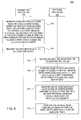
- FIG. 6 is a flowchart depicting a method 600 for view generation based on the video coding scheme, according to one embodiment presented in this disclosure.
- the method 600 begins at step 602, where the transmitting application 102 generates a first bitstream encoded based on the video coding scheme.
- the first bitstream includes video, one or more quantized warp map offsets, and a first message of a predefined message type specified by the video coding scheme.
- the first message contains syntax elements including a first syntax element and a second syntax element. Each syntax element is disposed at an arbitrarily defined offset within the first message. In other words, reference to the first syntax element does not necessarily imply that the first syntax element is first in order relative to other syntax elements in the first message. Depending on the embodiment, the first syntax element may be first in order, second in order, last in order, etc.
- the transmitting application 102 transmits the first bitstream to the receiving application 104.
- the receiving application 104 receives the first bitstream from the transmitting application.
- the receiving application 104 interprets, based on the first syntax element included in the first message, depth samples decoded from the first bitstream, as a first predefined depth format of quantized warp map offsets.
- the receiving application 104 generates one or more warp maps based on one or more quantized warp map offsets interpreted from the first bitstream, and based further on at least the second syntax element.
- the receiving application 104 generates one or more views using image-domain warping and based on the video and the one or more warp maps.
- FIG. 7 is a flowchart depicting a method 700 for view generation based on the video coding scheme, according to one embodiment presented in this disclosure.
- the method 700 begins at step 702, where the transmitting application generates a second bitstream encoded based on the video coding scheme.
- the second bitstream includes video, one or more depth maps, and a second message of the predefined message type specified by the video coding scheme.
- the video included in the second bitstream may be the same as or different from the video included in the first bitstream.
- the second message contains the first syntax element.
- the first syntax element in the second message specifies a depth type different than the first syntax element in the first message.
- the transmitting application 102 transmits the second bitstream to the receiving application 104.
- the receiving application 104 receives the second bitstream from the transmitting application 102.
- the receiving application 104 interprets, based on the first syntax element included in the second message, depth samples decoded from the second bitstream, as a second predefined format of depth maps.
- the receiving application 104 generates one or more views using depth-image-based rendering and based on the video and one or more depth maps interpreted from the second bitstream.
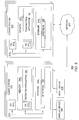
- FIG 8 is a block diagram illustrating components of the system 800 for view generation, according to one embodiment presented in this disclosure.
- the system 800 corresponds to the system 100 of Figure 1 .
- the system 800 includes a plurality of client systems 852 and a plurality of server systems 850.
- the client systems 852 are communicatively coupled via a network 803.
- the server systems 850 may also be communicatively coupled via the network 803 or via a network other than the network 803.
- the network 803 is an ad hoc network connecting multiple cellular phones.
- the client systems 852 may include existing computer systems, e.g., smartphones and other cellular phones, desktop computers, server computers, laptop computers, tablet computers, gaming consoles, hand-held or portable devices and the like.
- the client systems 852 illustrated in Figure 8 are merely examples of computer systems in which embodiments disclosed herein may be used.
- Embodiments disclosed herein may be implemented differently, regardless of whether the computer systems are complex multi-user computing systems, such as a cluster of individual computers connected by a highspeed network, single-user workstations, or network appliances lacking non-volatile storage.
- embodiments disclosed herein may be implemented using any device or computer system capable of performing the functions described herein.
- each client system 852 and server system 850 includes, without limitation, a processor 804, which obtains instructions and data via a bus 810 from a memory 806 and storage 808.
- the processor 804 is a programmable logic device that performs instruction, logic, and mathematical processing, and may be representative of one or more CPUs.
- the memory 806 is any memory sufficiently large to hold the necessary programs and data structures.
- the memory 806 could be one or a combination of memory devices, including Random Access Memory, nonvolatile or backup memory (e.g., programmable or Flash memories, read-only memories, etc.).
- the memory 806 includes an operating system (“OS") 812.
- OS operating system
- Operating system 812 is software used for managing the operation of the client system 852 or the server system 850.
- Examples of the OS 812 include UNIX, versions of the Microsoft Windows® operating system and distributions of the Linux® operating system. Additional examples of the OS 812 include custom operating systems for smartphones and gaming consoles, including the custom operating systems for systems such as the Microsoft Xbox 360®, Nintendo Wii® and Sony PlayStation® 3.
- the memory 806 1 of the client system 852 further includes the receiving application 104, which is configured according to embodiments described above.
- the memory 806 2 of the server system 850 further includes the transmitting application 102, which is also configured according to embodiments described above.
- the storage 808 is representative of hard-disk drives, flash memory devices, optical media and the like.
- the storage 808 stores application programs and data for use by the client systems 852.
- the memory 806 and the storage 808 may be considered to include memory physically located elsewhere; for example, on another computer coupled to the client system 852 or to the server system 850 via the bus 810.
- the client systems 852 and the server systems 850 include network interfaces for operably connecting to one another via a network, such as the network 803.
- the storage 808 2 of the server system 850 includes the bitstream 106 to be transmitted to the client system 852.
- the storage 808 1 of the client system 852 includes the bitstream 106 that is received from the server system 850, according to embodiments described above.
- the client systems 852 are each coupled to a display device 814.
- the display device 814 may include output devices such as cellular phone displays, movie theater displays, monitors, touch screen displays, and so forth.
- each client system 852 is also coupled to an input device 816.
- the input device 816 may include keypads, keyboards, mice, controllers, and so forth.
- aspects presented in this disclosure may be embodied as a system, method or computer program product. Accordingly, aspects disclosed herein may take the form of an entirely hardware embodiment, an entirely software embodiment (including firmware, resident software, micro-code, etc.) or an embodiment combining software and hardware aspects that may all generally be referred to herein as a "circuit,” “module” or “system.” Furthermore, aspects disclosed herein may take the form of a computer program product embodied in one or more computer readable medium(s) having computer readable program code embodied thereon.
- the computer readable medium may be a computer readable signal medium or a computer readable storage medium.
- a computer readable storage medium may be, for example, but not limited to, an electronic, magnetic, optical, electromagnetic, infrared, or semiconductor system, apparatus, or device, or any suitable combination of the foregoing.
- a computer readable storage medium may be any tangible medium that can contain, or store a program for use by or in connection with an instruction execution system, apparatus, or device.
- a computer readable signal medium may include a propagated data signal with computer readable program code embodied therein, for example, in baseband or as part of a carrier wave. Such a propagated signal may take any of a variety of forms, including, but not limited to, electro-magnetic, optical, or any suitable combination thereof.
- a computer readable signal medium may be any computer readable medium that is not a computer readable storage medium and that can communicate, propagate, or transport a program for use by or in connection with an instruction execution system, apparatus, or device.
- Program code embodied on a computer readable medium may be transmitted using any appropriate medium, including but not limited to wireless, wireline, optical fiber cable, RF, etc., or any suitable combination of the foregoing.
- Computer program code for carrying out operations for aspects disclosed herein may be written in any combination of one or more programming languages, including an object oriented programming language such as Java, Smalltalk, C++ or the like and conventional procedural programming languages, such as the "C" programming language or similar programming languages.
- the program code may execute entirely on the computer of a user, partly on the computer of the user, as a stand-alone software package, partly on the computer of the user and partly on a remote computer, or entirely on the remote computer or server.
- the remote computer may be connected to the computer of the user via any type of network, including a local area network (LAN) or a wide area network (WAN), or the connection may be made to an external computer (for example, through the Internet using an Internet Service Provider).
- LAN local area network
- WAN wide area network
- Internet Service Provider for example, AT&T, MCI, Sprint, EarthLink, MSN, GTE, etc.
- These computer program instructions may also be stored in a computer readable medium that can direct a computer, other programmable data processing apparatus, or other devices to function in a particular manner, such that the instructions stored in the computer readable medium produce an article of manufacture including instructions which implement the function/act specified in the flowchart or block diagram block or blocks.
- the computer program instructions may also be loaded onto a computer, other programmable data processing apparatus, or other devices to cause a series of operational steps to be performed on the computer, other programmable apparatus or other devices to produce a computer implemented process such that the instructions which execute on the computer or other programmable apparatus provide processes for implementing the functions/acts specified in the flowchart or block diagram block or blocks.
- Cloud computing generally refers to the provision of scalable computing resources as a service over a network. More formally, cloud computing may be defined as a computing capability that provides an abstraction between the computing resource and its underlying technical architecture (e.g., servers, storage, networks), enabling convenient, on-demand network access to a shared pool of configurable computing resources that can be rapidly provisioned and released with minimal management effort or service provider interaction.
- cloud computing allows a user to access virtual computing resources (e.g., storage, data, applications, and even complete virtualized computing systems) in "the cloud,” without regard for the underlying physical systems (or locations of those systems) used to provide the computing resources.
- cloud computing resources are provided to a user on a pay-peruse basis, where users are charged only for the computing resources actually used (e.g. an amount of storage space consumed by a user or a number of virtualized systems instantiated by the user).
- a user can access any of the resources that reside in the cloud at any time, and from anywhere across the Internet.
- the bitstream 106 may be stored in the cloud, and the transmitting application 102 or the receiving application 104 may additionally execute in the cloud, thereby improving accessibility of the bitstream 106 at least in some cases.
- each block in the flowchart or block diagrams may represent a module, segment, or portion of code, which comprises one or more executable instructions for implementing the specified logical function(s).
- the functions noted in the block may occur out of the order noted in the figures.
- two blocks shown in succession may, in fact, be executed substantially concurrently, or the blocks may sometimes be executed in the reverse order, depending upon the functionality involved.
- Each block of the block diagrams or flowchart illustration, and combinations of blocks in the block diagrams or flowchart illustration can be implemented by special-purpose hardware-based systems that perform the specified functions or acts, or combinations of special purpose hardware and computer instructions.
Landscapes
- Engineering & Computer Science (AREA)
- Multimedia (AREA)
- Signal Processing (AREA)
- Library & Information Science (AREA)
- Physics & Mathematics (AREA)
- General Physics & Mathematics (AREA)
- Theoretical Computer Science (AREA)
- Compression Or Coding Systems Of Tv Signals (AREA)
- Testing, Inspecting, Measuring Of Stereoscopic Televisions And Televisions (AREA)
Abstract
Description
- Human beings typically see using stereoscopic vision. The left and right eyes of an observer each perceives slightly different views of a scene, and the brain of the observer fuses the slightly different views into a single image that provides depth information. The depth information allows the observer to perceive the relative distance to various objects in the scene. Movies filmed with a single camera may not provide such depth information to the viewer and thus tend to look flat.
- Early efforts in 3-D movie technology used anaglyphs, in which two images of the same scene, with a relative offset between them, are superimposed on a single piece of movie film, with the images being subject to complimentary color filters (e.g., red and green). Viewers donned special glasses so that one image would be seen only by the left eye while the other would be seen only by the right eye. When the brains of the viewers fused the two images, the result was the illusion of depth. In the 1950s, "dual-strip" projection techniques were widely used to show 3-D movies. Using dual-strip projection techniques, two films were projected side-by-side in synchronism, with the light from each projector being oppositely polarized. Viewers wore polarizing glasses, and each eye would see only one of the two images. More recently, active polarization has been used to distinguish left-eye and right-eye images. Left-eye and right-eye images are projected sequentially using an active direction-flipping circular polarizer that applies opposite circular polarization to the left-eye and right-eye frames. The viewer dons glasses with opposite fixed circular polarizers for each eye, so that each eye sees only the intended frames. Various other systems for projecting 3-D movies have also been used over the years.
- The trend towards 3-D movies in theatres and in home entertainment systems has been growing. The 3-D movies may be produced using stereoscopic techniques. Stereoscopic techniques create an illusion of depth from a pair of 2-D images, each of which is presented to a separate eye of a viewer. The pair of 2-D images may represent two slightly different perspectives of a scene. The slightly different perspectives may resemble the natural, binocular vision of the eyes of the viewer. By presenting 2-D images of slightly different perspectives to the right eye and to the left eye of the viewer, respectively, the viewer may perceive a three dimensional composite of the 2-D images, in which certain objects of the scene appear nearer to the viewer than other objects of the scene. That is, the brain of the viewer may merge or fuse the left and right eye images to create a perception of depth.
- The degree of offset of objects in the image pair determines the depth at which the objects are perceived by the viewer. An object may appear to protrude toward the viewer and away from the neutral plane or screen when the position or coordinates of the left eye image are crossed with the position or coordinates of the right eye image (e.g., negative parallax). In contrast, an object may appear to recede or be behind the screen when the position or coordinates of the left eye image and of the right image are not crossed (e.g., positive parallax).
- It is increasingly common for movies to be filmed (in the case of live action movies) or imaged (in the case of rendered animations) in stereo for 3-D viewing. Image frames used to produce stereoscopic video (or stereo video) may be referred to as stereoscopic images. An image frame (or simply, frame) refers to an image at a specific point in time. An illusion of motion may be achieved by presenting multiple frames per second (fps) to the viewer, such as twenty-four to thirty fps. A frame may include content from a live action movie filmed with two or more cameras. A frame may also include content from a rendered animation that is imaged using two camera locations. In stereo video, stereoscopic perception results from the presenting a left eye image stream and a right eye image stream to the viewer.
- Embodiments presented in this disclosure provide a method, computer-readable medium, and system to perform an operation for view generation based on a video coding scheme. The operation includes receiving a first bitstream encoded based on the video coding scheme. The first bitstream includes video, one or more quantized warp map offsets, and a first message of a predefined message type specified by the video coding scheme. The first message contains a plurality of syntax elements including a first syntax element and a second syntax element. The operation also includes interpreting, based on the first syntax element included in the first message, depth samples decoded from the first bitstream, as a first predefined depth format comprising quantized warp map offsets. The operation also includes generating one or more warp maps based on one or more quantized warp map offsets interpreted from the first bitstream, and based further on at least the second syntax element. The operation also includes generating one or more views using image-domain warping and based on the video and one or more warp maps.
- Other embodiments presented herein provide a method of view generation based on a video coding scheme. The method includes generating a first bitstream encoded based on the video coding scheme. The first bitstream includes video, one or more quantized warp map offsets, and a first message of a predefined message type specified by the video coding scheme. The first message contains a plurality of syntax elements including a first syntax element and a second syntax element. The method also includes transmitting the first bitstream to a receiving entity. The receiving entity is configured to interpret, based on the first syntax element included in the first message, depth samples decoded from the first bitstream, as a first predefined depth format comprising quantized warp map offsets. The receiving entity is also configured to generate one or more warp maps based on one or more quantized warp map offsets interpreted from the first bitstream, and based further on at least the second syntax element. The receiving entity is also configured to generate one or more views using image-domain warping and based on the video and the one or more warp maps.
- So that the manner in which the above recited features presented in this disclosure can be understood in detail, a more particular description, briefly summarized above, may be had by reference to embodiments, some of which are illustrated in the appended drawings. It is to be noted, however, that the appended drawings illustrate only typical embodiments presented in this disclosure and are therefore not to be considered limiting of its scope, for the disclosure may admit to other equally effective embodiments.
-
Figure 1 is a data flow diagram illustrating a system for view generation based on a video coding scheme, according to one embodiment presented in this disclosure. -
Figure 2 depicts a syntax for a supplementary enhancement information (SEI) message, according to one embodiment presented in this disclosure. -
Figure 3 depicts pseudocode to derive a warp map from decoded depth samples and syntax elements provided by the SEI message, according to one embodiment presented in this disclosure. -
Figure 4 illustrates exemplary camera positions and associated warp maps, according to one embodiment presented in this disclosure. -
Figure 5 depicts pseudocode to derive a warp map used to synthesize a view at an arbitrary position using an input view at a different position, according to one embodiment presented in this disclosure. -
Figure 6 is a flowchart depicting a method for view generation based on the video coding scheme, according to one embodiment presented in this disclosure. -
Figure 7 is a flowchart depicting a method for view generation based on the video coding scheme, according to one embodiment presented in this disclosure. -
Figure 8 is a block diagram illustrating components of the system for view generation, according to one embodiment presented in this disclosure. - Embodiments presented in this disclosure provide techniques for view generation based on a video coding scheme. In some embodiments, views may be generated based on warp maps. It may often be desirable to generate multiple views, such as to support use of multiscopic displays, which facilitate stereoscopic viewing without the need for any spectacles to be worn by the user. In scenarios where warp maps are generated during content production, it may be desirable to transmit the warp maps - along with video data - to the users, in order to facilitate generating multiple views by the receiving application. The warp maps may be transmitted based on the video coding scheme and according to embodiments disclosed herein.
- In one embodiment, the video coding scheme may be tailored to facilitate transmission of a bitstream containing multi-view video and depth map data. In one embodiment, quantized warp map offsets are transmitted in the bitstream, where the quantized warp map offsets may have the same format as depth maps. Quantized warp map offsets may also be referred to herein as quantized map offsets. So that the receiving application can appropriately interpret the received bitstream, a predefined message is submitted in the bitstream. In one embodiment, the video coding scheme is a High Efficiency Video Coding (HEVC) extension for 3D video coding (3D-HEVC), and the predefined message is a supplementary enhancement information (SEI) message.
- In one embodiment, the message indicates, to the receiving application, that image-domain warping - rather than depth-image-based rendering - is to be used as a view synthesis technique. Additionally or alternatively, the message indicates, to the receiving application, that depth samples decoded from the bitstream are to be interpreted as quantized warp map offsets as opposed to depth samples such as a depth map. The message may also indicate, to the receiving application, that syntax elements included in the message are to be used to generate warp maps based on the quantized warp map offsets. The message may also indicate, to the receiving application, that the generated warp maps are to be used for view generation based on image-domain warping. Further, the message need not necessarily be transmitted in some cases, such as where it is desired to transmit multi-view video and depth map data based on the video coding scheme. In such cases, the receiving application uses depth-image-based rendering in lieu of image-domain warping, to generate views. The syntax and semantics associated with the message are specified in the present disclosure, including Appendices A-B attached hereto.
- At least in some embodiments, warp maps may often be generated more efficiently or conveniently than depth maps. For instance, warp map generation may often not require as much human intervention as depth map generation. In some embodiments, warp map generation may be substantially or even fully automatic. By using the techniques disclosed herein to generate views based on warp maps, the views may also be generated more efficiently or conveniently at least in some cases.
-
Figure 1 is a data flow diagram illustrating asystem 100 for view generation based on a video coding scheme, according to one embodiment presented in this disclosure. As shown, thesystem 100 includes a transmittingapplication 102 and a receivingapplication 104. In one embodiment, the transmittingapplication 102 generates abitstream 106 encoded based on the video coding scheme. Thebitstream 106 includesvideo 112, quantized warp map offsets 116, and amessage 114 of a message type specified by the video coding scheme. Themessage 114 containssyntax elements 118. The transmittingapplication 102 transmits thebitstream 106 to the receivingapplication 104. The receivingapplication 104 receives thebitstream 106 and interprets, based on afirst syntax element 118 included in themessage 114, depth samples decoded from thebitstream 106, as a first depth format of quantized warp map offsets. The receivingapplication 104 then generates warp maps 108 based on quantized warp map offsets interpreted from thebitstream 106 and based further on asecond syntax element 118 included in themessage 114. The receivingapplication 104 then generatesviews 110 using image-domain warping and based on thevideo 112 and the warp maps 108. - In one embodiment, the video coding scheme is 3D-HEVC, and the message type is the SEI message type. The
video 112 may be multi-view video. Further, image-domain warping may be used in lieu of depth-image-based rendering, and the depth samples may be interpreted as quantized warp map offsets in lieu of depth maps. In some embodiments, multi-view video and depth map data are transmitted using 3D-HEVC and in lieu of an SEI message. The first syntax element may specify any of a plurality of predefined depth types, such as quantized warp map offsets, depth maps, and so forth. -
Figure 2 depicts asyntax 200 for an SEI message, according to one embodiment presented in this disclosure. Thesyntax 200 specifiessyntax elements 202 in the SEI message anddescriptors 204, each indicating a predefined parsing process for respective syntax element. In one embodiment, the SEI message signals to interpret decoded depth samples as an alternative depth format. Afirst syntax element 206 in the SEI message specifies a desired, alternative depth type. In one embodiment, a depth type value of zero indicates to use decoded depth samples to derive a warp map and further indicates to perform view synthesis via image-domain warping, while other depth type values, e.g., one through three, are reserved values. In one embodiment, a predefined depth type value, other than zero, indicates to perform view synthesis based on depth-image-based rendering rather than based on image-domain warping. - In one embodiment, additional syntax elements contained in the SEI message are used to derive corresponding warp maps from decoded depth samples of each view. For instance, a
second syntax element 208 in the SEI message specifies an integer part of a minimum offset for a horizontal direction of a warp map. Athird syntax element 210 specifies a fractional part of the minimum offset for the horizontal direction of the warp map. Thesesyntax elements 
Similarly, afourth syntax element 212 specifies an integer part of a maximum offset for the horizontal direction of the warp map. Afifth syntax element 214 specifies a fractional part of the maximum offset for the horizontal direction of the warp map. Thesyntax elements 
- In one embodiment, a
sixth syntax element 216 in the SEI message is a flag that, when set, indicates the presence of minimum and maximum offset values for the vertical direction. Aseventh syntax element 218 specifies an integer part of a minimum offset for a vertical direction of the warp map. Aneighth syntax element 220 species a fractional part of the minimum offset for the vertical direction of the warp map. Thesyntax elements 
Similarly, aninth syntax element 222 specifies an integer part of a maximum offset for the vertical direction of the warp map. Atenth syntax element 224 specifies a fractional part of the maximum offset for the vertical direction of the warp map. Thesyntax elements 
- In one embodiment, an
eleventh syntax element 226 in the SEI message is a flag that, when set, specifies the presence of a new warp map size that is valid for the current and all ensuing warp maps in output order, until another new warp map size is explicitly specified. When cleared, the flag specifies that the warp map size remains unchanged. Twelfth andthirteenth syntax elements syntax elements 
Although embodiments herein are described with reference to thesyntax 200 and thesyntax elements 202, this is not intended to be limiting of disclosed embodiments, and other syntaxes, syntax elements, descriptors, and values are broadly contemplated in the present disclosure. -
Figure 3 depictspseudocode 300 to derive a warp map from decoded depth samples and syntax elements provided by the SEI message, according to one embodiment presented in this disclosure. As shown, thepseudocode 300 iterates though the width and height of the warp map, respectively, deriving each value of the warp map based on the decoded depth samples and syntax elements. In such a manner, decoded depth samples of each view are used to derive a corresponding warp map for the respective view. The decoded depth samples and the warp map are represented in thepseudocode 300 as d and w, respectively. In one embodiment, each warp map so derived is assigned to its corresponding input view. Further, each warp map has a property to map the corresponding input view to a central camera position. -
Figure 4 illustrates exemplary camera positions and associated warp maps 406, according to one embodiment presented in this disclosure. As indicated by alegend 408, the camera positions include input camera positions 402 and central camera positions 404. In this particular example, only the warp map WA,M_AB of the leftmost input view maps its corresponding input view to a central camera position 4041 to its right. In contrast, the other warps maps WB,M_AB, WC,M_BC, WD,M_CD map their corresponding input views to central camera positions 4041, 4042, 4043 to their left, respectively. -
Figure 5 depictspseudocode 500 to derive a warp map used to synthesize a view at an arbitrary position Q using an input view at position P, according to one embodiment presented in this disclosure. Position P corresponds to either positions A, B, C, or D inFigure 4 . The warp map, represented in thepseudocode 500 as w_pq, is derived from a warp map w_pm, which maps the same input view to a central camera position M inFigure 4 . The warp map w_pq is then used to synthesize the texture for a view at position Q from texture of a view at position P. - In one embodiment, warp map samples are interpreted as a two-dimensional sub-pixel position in the synthesized view, to which the color samples of the input view at the sub-pixel position (x*deltax, y*deltax) are mapped. The warp map samples are represented in the pseudocode as w_pq[x][y][0] and w_pq[x][y][1]. A warp map also represents a mapping of color samples of quads of the input view to corresponding quads in the synthesized view. In one embodiment, the quads of the input view are defined by four positions given by:

The corresponding quads in the synthesized view are defined by corresponding positions given by:
- Thus, the quad-based color mapping process described above provides synthesis of an arbitrary view at position Q from an input view at position P and a warp map w_pq, where the warp map w_pq is derived from a warp map w_pm, which is in turn derived from decoded depth samples and syntax elements provided by the SEI message. Depending on the embodiment, the position of a view to synthesize may not necessarily be disposed between two input views. In cases where the view is indeed disposed between two input views, then two different versions of the view may be synthesized, including a first version based on the closest input view to its left, and a second version based on the closest input view to its right. A final synthesized view may then be computed by combining both results via a predefined view composition technique, e.g., pixel-wise blending. On the other hand, in cases where the view to synthesize is not disposed between input views, then the closest input view may be used to synthesize the view.
-
Figure 6 is a flowchart depicting amethod 600 for view generation based on the video coding scheme, according to one embodiment presented in this disclosure. As shown, themethod 600 begins atstep 602, where the transmittingapplication 102 generates a first bitstream encoded based on the video coding scheme. The first bitstream includes video, one or more quantized warp map offsets, and a first message of a predefined message type specified by the video coding scheme. The first message contains syntax elements including a first syntax element and a second syntax element. Each syntax element is disposed at an arbitrarily defined offset within the first message. In other words, reference to the first syntax element does not necessarily imply that the first syntax element is first in order relative to other syntax elements in the first message. Depending on the embodiment, the first syntax element may be first in order, second in order, last in order, etc. Atstep 604, the transmittingapplication 102 transmits the first bitstream to the receivingapplication 104. - At
step 606, the receivingapplication 104 receives the first bitstream from the transmitting application. Atstep 608, the receivingapplication 104 interprets, based on the first syntax element included in the first message, depth samples decoded from the first bitstream, as a first predefined depth format of quantized warp map offsets. Atstep 610, the receivingapplication 104 generates one or more warp maps based on one or more quantized warp map offsets interpreted from the first bitstream, and based further on at least the second syntax element. Atstep 612, the receivingapplication 104 generates one or more views using image-domain warping and based on the video and the one or more warp maps. -
Figure 7 is a flowchart depicting amethod 700 for view generation based on the video coding scheme, according to one embodiment presented in this disclosure. As shown, themethod 700 begins atstep 702, where the transmitting application generates a second bitstream encoded based on the video coding scheme. The second bitstream includes video, one or more depth maps, and a second message of the predefined message type specified by the video coding scheme. Depending on the embodiment, the video included in the second bitstream may be the same as or different from the video included in the first bitstream. The second message contains the first syntax element. The first syntax element in the second message specifies a depth type different than the first syntax element in the first message. Atstep 704, the transmittingapplication 102 transmits the second bitstream to the receivingapplication 104. - At
step 706, the receivingapplication 104 receives the second bitstream from the transmittingapplication 102. Atstep 708, the receivingapplication 104 interprets, based on the first syntax element included in the second message, depth samples decoded from the second bitstream, as a second predefined format of depth maps. Atstep 710, the receivingapplication 104 generates one or more views using depth-image-based rendering and based on the video and one or more depth maps interpreted from the second bitstream. -
Figure 8 is a block diagram illustrating components of thesystem 800 for view generation, according to one embodiment presented in this disclosure. Thesystem 800 corresponds to thesystem 100 ofFigure 1 . As shown, thesystem 800 includes a plurality ofclient systems 852 and a plurality ofserver systems 850. Theclient systems 852 are communicatively coupled via anetwork 803. In some embodiments, theserver systems 850 may also be communicatively coupled via thenetwork 803 or via a network other than thenetwork 803. In one embodiment, thenetwork 803 is an ad hoc network connecting multiple cellular phones. - In one embodiment, the
client systems 852 may include existing computer systems, e.g., smartphones and other cellular phones, desktop computers, server computers, laptop computers, tablet computers, gaming consoles, hand-held or portable devices and the like. Theclient systems 852 illustrated inFigure 8 , however, are merely examples of computer systems in which embodiments disclosed herein may be used. Embodiments disclosed herein may be implemented differently, regardless of whether the computer systems are complex multi-user computing systems, such as a cluster of individual computers connected by a highspeed network, single-user workstations, or network appliances lacking non-volatile storage. Moreover, it is explicitly contemplated that embodiments disclosed herein may be implemented using any device or computer system capable of performing the functions described herein. - As shown, each
client system 852 andserver system 850 includes, without limitation, a processor 804, which obtains instructions and data via a bus 810 from a memory 806 andstorage 808. The processor 804 is a programmable logic device that performs instruction, logic, and mathematical processing, and may be representative of one or more CPUs. The memory 806 is any memory sufficiently large to hold the necessary programs and data structures. The memory 806 could be one or a combination of memory devices, including Random Access Memory, nonvolatile or backup memory (e.g., programmable or Flash memories, read-only memories, etc.). - As shown, the memory 806 includes an operating system ("OS") 812. Operating system 812 is software used for managing the operation of the
client system 852 or theserver system 850. Examples of the OS 812 include UNIX, versions of the Microsoft Windows® operating system and distributions of the Linux® operating system. Additional examples of the OS 812 include custom operating systems for smartphones and gaming consoles, including the custom operating systems for systems such as the Microsoft Xbox 360®, Nintendo Wii® and Sony PlayStation® 3. As shown, the memory 8061 of theclient system 852 further includes the receivingapplication 104, which is configured according to embodiments described above. The memory 8062 of theserver system 850 further includes the transmittingapplication 102, which is also configured according to embodiments described above. - In one embodiment, the
storage 808 is representative of hard-disk drives, flash memory devices, optical media and the like. Generally, thestorage 808 stores application programs and data for use by theclient systems 852. In addition, the memory 806 and thestorage 808 may be considered to include memory physically located elsewhere; for example, on another computer coupled to theclient system 852 or to theserver system 850 via the bus 810. Theclient systems 852 and theserver systems 850 include network interfaces for operably connecting to one another via a network, such as thenetwork 803. As shown, thestorage 8082 of theserver system 850 includes thebitstream 106 to be transmitted to theclient system 852. Thestorage 8081 of theclient system 852 includes thebitstream 106 that is received from theserver system 850, according to embodiments described above. - In one embodiment, the
client systems 852 are each coupled to adisplay device 814. Thedisplay device 814 may include output devices such as cellular phone displays, movie theater displays, monitors, touch screen displays, and so forth. In some embodiments, eachclient system 852 is also coupled to aninput device 816. Theinput device 816 may include keypads, keyboards, mice, controllers, and so forth. - In the preceding, reference is made to embodiments presented in this disclosure. However, the scope of the present disclosure is not limited to specific described embodiments. Instead, any combination of the following features and elements, whether related to different embodiments or not, is contemplated to implement and practice contemplated embodiments. Furthermore, although embodiments disclosed herein may achieve advantages over other possible solutions or over the prior art, whether or not a particular advantage is achieved by a given embodiment is not limiting of the scope of the present disclosure. Thus, the preceding aspects, features, embodiments and advantages are merely illustrative and are not considered elements or limitations of the appended claims except where explicitly recited in a claim(s). Likewise, reference to "the invention" shall not be construed as a generalization of any inventive subject matter disclosed herein and shall not be considered to be an element or limitation of the appended claims except where explicitly recited in a claim(s).
- Aspects presented in this disclosure may be embodied as a system, method or computer program product. Accordingly, aspects disclosed herein may take the form of an entirely hardware embodiment, an entirely software embodiment (including firmware, resident software, micro-code, etc.) or an embodiment combining software and hardware aspects that may all generally be referred to herein as a "circuit," "module" or "system." Furthermore, aspects disclosed herein may take the form of a computer program product embodied in one or more computer readable medium(s) having computer readable program code embodied thereon.
- Any combination of one or more computer readable medium(s) may be utilized. The computer readable medium may be a computer readable signal medium or a computer readable storage medium. A computer readable storage medium may be, for example, but not limited to, an electronic, magnetic, optical, electromagnetic, infrared, or semiconductor system, apparatus, or device, or any suitable combination of the foregoing. More specific examples (a non-exhaustive list) of the computer readable storage medium would include the following: an electrical connection having one or more wires, a portable computer diskette, a hard disk, a random access memory (RAM), a read-only memory (ROM), an erasable programmable read-only memory (EPROM or Flash memory), an optical fiber, a portable compact disc read-only memory (CD-ROM), an optical storage device, a magnetic storage device, or any suitable combination of the foregoing. In the context of this disclosure, a computer readable storage medium may be any tangible medium that can contain, or store a program for use by or in connection with an instruction execution system, apparatus, or device.
- A computer readable signal medium may include a propagated data signal with computer readable program code embodied therein, for example, in baseband or as part of a carrier wave. Such a propagated signal may take any of a variety of forms, including, but not limited to, electro-magnetic, optical, or any suitable combination thereof. A computer readable signal medium may be any computer readable medium that is not a computer readable storage medium and that can communicate, propagate, or transport a program for use by or in connection with an instruction execution system, apparatus, or device.
- Program code embodied on a computer readable medium may be transmitted using any appropriate medium, including but not limited to wireless, wireline, optical fiber cable, RF, etc., or any suitable combination of the foregoing.
- Computer program code for carrying out operations for aspects disclosed herein may be written in any combination of one or more programming languages, including an object oriented programming language such as Java, Smalltalk, C++ or the like and conventional procedural programming languages, such as the "C" programming language or similar programming languages. The program code may execute entirely on the computer of a user, partly on the computer of the user, as a stand-alone software package, partly on the computer of the user and partly on a remote computer, or entirely on the remote computer or server. In the latter scenario, the remote computer may be connected to the computer of the user via any type of network, including a local area network (LAN) or a wide area network (WAN), or the connection may be made to an external computer (for example, through the Internet using an Internet Service Provider).
- Aspects presented in this disclosure are described above with reference to flowchart illustrations or block diagrams of methods, apparatus (systems) and computer program products according to embodiments disclosed herein. It will be understood that each block of the flowchart illustrations or block diagrams, and combinations of blocks in the flowchart illustrations or block diagrams, can be implemented by computer program instructions. These computer program instructions may be provided to a processor of a general purpose computer, special purpose computer, or other programmable data processing apparatus to produce a machine, such that the instructions, which execute via the processor of the computer or other programmable data processing apparatus, create means for implementing the functions/acts specified in the flowchart or block diagram block or blocks.
- These computer program instructions may also be stored in a computer readable medium that can direct a computer, other programmable data processing apparatus, or other devices to function in a particular manner, such that the instructions stored in the computer readable medium produce an article of manufacture including instructions which implement the function/act specified in the flowchart or block diagram block or blocks.
- The computer program instructions may also be loaded onto a computer, other programmable data processing apparatus, or other devices to cause a series of operational steps to be performed on the computer, other programmable apparatus or other devices to produce a computer implemented process such that the instructions which execute on the computer or other programmable apparatus provide processes for implementing the functions/acts specified in the flowchart or block diagram block or blocks.
- Embodiments disclosed herein may be provided to end users through a cloud computing infrastructure. Cloud computing generally refers to the provision of scalable computing resources as a service over a network. More formally, cloud computing may be defined as a computing capability that provides an abstraction between the computing resource and its underlying technical architecture (e.g., servers, storage, networks), enabling convenient, on-demand network access to a shared pool of configurable computing resources that can be rapidly provisioned and released with minimal management effort or service provider interaction. Thus, cloud computing allows a user to access virtual computing resources (e.g., storage, data, applications, and even complete virtualized computing systems) in "the cloud," without regard for the underlying physical systems (or locations of those systems) used to provide the computing resources.
- Typically, cloud computing resources are provided to a user on a pay-peruse basis, where users are charged only for the computing resources actually used (e.g. an amount of storage space consumed by a user or a number of virtualized systems instantiated by the user). A user can access any of the resources that reside in the cloud at any time, and from anywhere across the Internet. In context of the present disclosure, the
bitstream 106 may be stored in the cloud, and the transmittingapplication 102 or the receivingapplication 104 may additionally execute in the cloud, thereby improving accessibility of thebitstream 106 at least in some cases. - The flowchart and block diagrams in the Figures illustrate the architecture, functionality, and operation of possible implementations of systems, methods and computer program products according to various embodiments disclosed herein. In this regard, each block in the flowchart or block diagrams may represent a module, segment, or portion of code, which comprises one or more executable instructions for implementing the specified logical function(s). In some alternative implementations, the functions noted in the block may occur out of the order noted in the figures. For example, two blocks shown in succession may, in fact, be executed substantially concurrently, or the blocks may sometimes be executed in the reverse order, depending upon the functionality involved. Each block of the block diagrams or flowchart illustration, and combinations of blocks in the block diagrams or flowchart illustration, can be implemented by special-purpose hardware-based systems that perform the specified functions or acts, or combinations of special purpose hardware and computer instructions.
- While the foregoing is directed to embodiments presented in this disclosure, other and further embodiments may be devised without departing from the basic scope of contemplated embodiments. That is, although specific embodiments and numerous specific details are set forth to provide a more thorough understanding of the present disclosure, persons skilled in the art, however, will understand that various modifications and changes may be made thereto without departing from the broader spirit and scope of the disclosure. The foregoing description and drawings are, accordingly, to be regarded in an illustrative rather than a restrictive sense.
Claims (10)
- A computer-implemented method of view generation based on a video coding scheme, the method comprising:receiving a first bitstream encoded based on the video coding scheme, wherein the first bitstream includes video, one or more quantized warp map offsets, and a first message of a predefined message type specified by the video coding scheme, wherein the first message contains a plurality of syntax elements including a first syntax element and a second syntax element;interpreting, based on the first syntax element included in the first message and by operation of one or more computer processors, depth samples decoded from the first bitstream, as a first predefined depth format comprising quantized warp map offsets;generating one or more warp maps based on one or more quantized warp map offsets interpreted from the first bitstream, and based further on at least the second syntax element; andgenerating one or more views using image-domain warping and based on the video and one or more warp maps.
- The computer-implemented method of claim 1, wherein the video coding scheme comprises a High Efficiency Video Coding extension for 3D video coding (3D-HEVC).
- The computer-implemented method of claim 1 or 2, wherein the predefined message type comprises a supplementary enhancement information (SEI) message type, wherein the first syntax element is disposed at an arbitrary offset within the first message, wherein the video comprises multiview autostereoscopic video.
- The computer-implemented method of any one of claims 1 to 3, wherein the image-domain warping is used in lieu of depth-image-based rendering, wherein in a first instance, the decoded depth samples are not interpreted as depth maps.
- The computer-implemented method of claim 4, wherein the first message is transmitted in the first instance, and wherein in a second instance, the video and depth map data are transmitted using 3D-HEVC and in lieu of the first message.
- The computer-implemented method of any one of claims 1 to 5, wherein the first syntax element specifies one of a plurality of distinct, predefined depth types.
- The computer-implemented method of claim 6, wherein the one or more views are generated by an application, wherein the application is configured to:receive a second bitstream encoded based on the video coding scheme, wherein the second bitstream includes video, one or more depth maps, and a second message of the predefined message type specified by the video coding scheme, wherein the second message contains the first syntax element, wherein the first syntax element in the second message specifies a depth type different than the first syntax element in the first message;interpret, based on the first syntax element included in the second message, depth samples decoded from the bitstream, as a second predefined depth format comprising depth maps; andgenerate one or more views using depth-image-based rendering and based on the video and one or more depth maps interpreted from the second bitstream.
- A computer-implemented method of view generation based on a video coding scheme, the method comprising:generating, by operation of one or more computer processors, a first bitstream encoded based on the video coding scheme, wherein the first bitstream includes video, one or more quantized warp map offsets, and a first message of a predefined message type specified by the video coding scheme, wherein the first message contains a plurality of syntax elements including a first syntax element and a second syntax element; andtransmitting the first bitstream to a receiving entity configured to:interpret, based on the first syntax element included in the first message, depth samples decoded from the first bitstream, as a first predefined depth format comprising quantized warp map offsets;generate one or more warp maps based on one or more quantized warp map offsets interpreted from the first bitstream, and based further on at least the second syntax element; andgenerate one or more views using image-domain warping and based on the video and the one or more warp maps.
- A computer-readable storage medium comprising computer executable instructions that when executed by a computer will cause the computer to carry out a method according to any one of the preceding claims.
- A system for view generation based on a video coding scheme, the system comprising:one or more computer processors; anda computer-readable storage medium comprising computer executable instructions that when executed by the one or more computer processors will cause the processor to carry out a method according to any one claims 1 to 7.
Applications Claiming Priority (1)
| Application Number | Priority Date | Filing Date | Title |
|---|---|---|---|
| US201361811473P | 2013-04-12 | 2013-04-12 |
Publications (2)
| Publication Number | Publication Date |
|---|---|
| EP2790410A1 true EP2790410A1 (en) | 2014-10-15 |
| EP2790410B1 EP2790410B1 (en) | 2025-01-08 |
Family
ID=50624403
Family Applications (1)
| Application Number | Title | Priority Date | Filing Date |
|---|---|---|---|
| EP14164611.7A Active EP2790410B1 (en) | 2013-04-12 | 2014-04-14 | Signalling warp maps using a high efficiency video coding (HEVC) extension for 3D video coding |
Country Status (3)
| Country | Link |
|---|---|
| US (3) | US9571812B2 (en) |
| EP (1) | EP2790410B1 (en) |
| CN (2) | CN104104938B (en) |
Cited By (1)
| Publication number | Priority date | Publication date | Assignee | Title |
|---|---|---|---|---|
| WO2016148853A1 (en) * | 2015-03-19 | 2016-09-22 | Microsoft Technology Licensing, Llc | Packaging/mux and unpackaging/demux of geometric data together with video data |
Families Citing this family (5)
| Publication number | Priority date | Publication date | Assignee | Title |
|---|---|---|---|---|
| EP3301933A1 (en) * | 2016-09-30 | 2018-04-04 | Thomson Licensing | Methods, devices and stream to provide indication of mapping of omnidirectional images |
| US10560678B2 (en) * | 2016-11-09 | 2020-02-11 | Mediatek Inc. | Method and apparatus having video encoding function with syntax element signaling of rotation information of content-oriented rotation applied to 360-degree image content or 360-degree video content represented in projection format and associated method and apparatus having video decoding function |
| US10432944B2 (en) | 2017-08-23 | 2019-10-01 | Avalon Holographics Inc. | Layered scene decomposition CODEC system and methods |
| TWI909057B (en) * | 2021-06-02 | 2025-12-21 | 美商杜拜研究特許公司 | Method, encoder, and display device for representing a three-dimensional scene and depth-plane data thereof |
| US11936913B2 (en) * | 2021-06-28 | 2024-03-19 | Tencent America LLC | Warping-based decoded picture resampling supplementary enhancement information message |
Family Cites Families (32)
| Publication number | Priority date | Publication date | Assignee | Title |
|---|---|---|---|---|
| FR2724033B1 (en) | 1994-08-30 | 1997-01-03 | Thomson Broadband Systems | SYNTHESIS IMAGE GENERATION METHOD |
| US6108005A (en) | 1996-08-30 | 2000-08-22 | Space Corporation | Method for producing a synthesized stereoscopic image |
| GB2372659A (en) | 2001-02-23 | 2002-08-28 | Sharp Kk | A method of rectifying a stereoscopic image |
| US6956566B2 (en) | 2002-05-23 | 2005-10-18 | Hewlett-Packard Development Company, L.P. | Streaming of images with depth for three-dimensional graphics |
| US7397929B2 (en) | 2002-09-05 | 2008-07-08 | Cognex Technology And Investment Corporation | Method and apparatus for monitoring a passageway using 3D images |
| US8094927B2 (en) | 2004-02-27 | 2012-01-10 | Eastman Kodak Company | Stereoscopic display system with flexible rendering of disparity map according to the stereoscopic fusing capability of the observer |
| CA2511040A1 (en) | 2004-09-23 | 2006-03-23 | The Governors Of The University Of Alberta | Method and system for real time image rendering |
| US7720282B2 (en) | 2005-08-02 | 2010-05-18 | Microsoft Corporation | Stereo image segmentation |
| US20070165942A1 (en) | 2006-01-18 | 2007-07-19 | Eastman Kodak Company | Method for rectifying stereoscopic display systems |
| EP2632163A3 (en) * | 2006-07-20 | 2013-11-27 | Thomson Licensing | Method and apparatus for signaling view scalability in multi-view video coding |
| JP5138031B2 (en) | 2007-05-11 | 2013-02-06 | コーニンクレッカ フィリップス エレクトロニクス エヌ ヴィ | Method, apparatus and system for processing depth related information |
| EP2501137A3 (en) | 2007-06-11 | 2012-12-12 | Samsung Electronics Co., Ltd. | Method and apparatus for generating header information of stereoscopic image |
| US8390674B2 (en) | 2007-10-10 | 2013-03-05 | Samsung Electronics Co., Ltd. | Method and apparatus for reducing fatigue resulting from viewing three-dimensional image display, and method and apparatus for generating data stream of low visual fatigue three-dimensional image |
| EP2063648A1 (en) | 2007-11-24 | 2009-05-27 | Barco NV | Sensory unit for a 3-dimensional display |
| KR101506217B1 (en) | 2008-01-31 | 2015-03-26 | 삼성전자주식회사 | A method and apparatus for generating a stereoscopic image data stream for reproducing a partial data section of a stereoscopic image, and a method and an apparatus for reproducing a partial data section of a stereoscopic image |
| US8228327B2 (en) | 2008-02-29 | 2012-07-24 | Disney Enterprises, Inc. | Non-linear depth rendering of stereoscopic animated images |
| JP5536676B2 (en) | 2008-03-04 | 2014-07-02 | トムソン ライセンシング | Virtual reference view |
| KR101506219B1 (en) * | 2008-03-25 | 2015-03-27 | 삼성전자주식회사 | Method and apparatus for providing and reproducing 3 dimensional video content, and computer readable medium thereof |
| WO2010019926A1 (en) | 2008-08-14 | 2010-02-18 | Real D | Stereoscopic depth mapping |
| KR101520620B1 (en) | 2008-08-18 | 2015-05-18 | 삼성전자주식회사 | Method and apparatus for determining a two- or three-dimensional display mode of an image sequence |
| EP2675175A3 (en) | 2008-10-03 | 2014-07-23 | Real D Inc. | Optimal depth mapping |
| EP2332340B1 (en) | 2008-10-10 | 2015-12-23 | Koninklijke Philips N.V. | A method of processing parallax information comprised in a signal |
| US8374462B2 (en) | 2008-11-14 | 2013-02-12 | Seiko Epson Corporation | Content-aware image and video resizing by anchor point sampling and mapping |
| US8750632B2 (en) * | 2008-12-26 | 2014-06-10 | JVC Kenwood Corporation | Apparatus and method for encoding images from multiple viewpoints and associated depth information |
| US20100302234A1 (en) | 2009-05-27 | 2010-12-02 | Chunghwa Picture Tubes, Ltd. | Method of establishing dof data of 3d image and system thereof |
| US9131279B2 (en) | 2009-08-06 | 2015-09-08 | Qualcomm Incorporated | Preparing video data in accordance with a wireless display protocol |
| US8711204B2 (en) | 2009-11-11 | 2014-04-29 | Disney Enterprises, Inc. | Stereoscopic editing for video production, post-production and display adaptation |
| US9445072B2 (en) | 2009-11-11 | 2016-09-13 | Disney Enterprises, Inc. | Synthesizing views based on image domain warping |
| JP5660361B2 (en) * | 2010-03-26 | 2015-01-28 | ソニー株式会社 | Image processing apparatus and method, and program |
| US9485492B2 (en) * | 2010-09-14 | 2016-11-01 | Thomson Licensing Llc | Compression methods and apparatus for occlusion data |
| US9615079B2 (en) * | 2011-03-18 | 2017-04-04 | Sony Corporation | Image processing apparatus and image processing method |
| CN104769940B (en) * | 2012-04-13 | 2017-07-11 | 皇家飞利浦有限公司 | Depth signaling data |
-
2013
- 2013-12-26 US US14/141,088 patent/US9571812B2/en active Active
-
2014
- 2014-04-14 CN CN201410148296.1A patent/CN104104938B/en active Active
- 2014-04-14 CN CN201611027262.2A patent/CN107071381B/en active Active
- 2014-04-14 EP EP14164611.7A patent/EP2790410B1/en active Active
-
2017
- 2017-01-26 US US15/417,158 patent/US10033983B2/en active Active
-
2018
- 2018-06-25 US US16/017,751 patent/US10757391B2/en active Active
Non-Patent Citations (5)
| Title |
|---|
| ALJOSCHA SMOLIC ET AL: "Image Domain Warping as Alternative to DIBR for Advanced 3DV Applications", 96. MPEG MEETING; 21-3-2011 - 25-3-2011; GENEVA; (MOTION PICTURE EXPERT GROUP OR ISO/IEC JTC1/SC29/WG11),, no. m19995, 15 March 2011 (2011-03-15), XP030048562 * |
| NIKOLCE STEFANOSKI ET AL: "3DV: Results on coding of warps using HEVC", 1. JCT-3V MEETING; 101. MPEG MEETING; 16-7-2012 - 20-7-2012; STOCKHOLM; (THE JOINT COLLABORATIVE TEAM ON 3D VIDEO CODING EXTENSION DEVELOPMENT OF ISO/IEC JTC1/SC29/WG11 AND ITU-T SG.16 ); URL: HTTP://PHENIX.INT-EVRY.FR/JCT2/,, no. JCT3V-A0004, 10 July 2012 (2012-07-10), XP030130003 * |
| STEFANOSKI N ET AL: "AHG8: Draft Text for Signaling Warp Maps as an Alternative 3D Format in 3D-HEVC", 4. JCT-3V MEETING; 20-4-2013 - 26-4-2013; INCHEON; (THE JOINT COLLABORATIVE TEAM ON 3D VIDEO CODING EXTENSION DEVELOPMENT OF ISO/IEC JTC1/SC29/WG11 AND ITU-T SG.16 ); URL: HTTP://PHENIX.INT-EVRY.FR/JCT2/,, no. JCT3V-D0103, 13 April 2013 (2013-04-13), XP030130767 * |
| TAKANORI SENOH ET AL: "AHG8: Draft Text for Signaling Global View and Depth as an Alternative 3D Format in 3D-HEVC", 4. JCT-3V MEETING; 20-4-2013 - 26-4-2013; INCHEON; (THE JOINT COLLABORATIVE TEAM ON 3D VIDEO CODING EXTENSION DEVELOPMENT OF ISO/IEC JTC1/SC29/WG11 AND ITU-T SG.16 ); URL: HTTP://PHENIX.INT-EVRY.FR/JCT2/,, no. JCT3V-D0272, 15 April 2013 (2013-04-15), XP030130936 * |
| TAKANORI SENOH ET AL: "AHG8: Draft Text for Signaling of Alternative 3D Format in ISO/IEC 14496-10 (ITU-T H.264)", 3. JCT-3V MEETING; 103. MPEG MEETING; 17-1-2013 - 23-1-2013; GENEVA; (THE JOINT COLLABORATIVE TEAM ON 3D VIDEO CODING EXTENSION DEVELOPMENT OF ISO/IEC JTC1/SC29/WG11 AND ITU-T SG.16 ); URL: HTTP://PHENIX.INT-EVRY.FR/JCT2/,, no. JCT3V-C0048, 10 January 2013 (2013-01-10), XP030130464 * |
Cited By (1)
| Publication number | Priority date | Publication date | Assignee | Title |
|---|---|---|---|---|
| WO2016148853A1 (en) * | 2015-03-19 | 2016-09-22 | Microsoft Technology Licensing, Llc | Packaging/mux and unpackaging/demux of geometric data together with video data |
Also Published As
| Publication number | Publication date |
|---|---|
| CN104104938A (en) | 2014-10-15 |
| CN104104938B (en) | 2017-01-11 |
| US10033983B2 (en) | 2018-07-24 |
| US20180309975A1 (en) | 2018-10-25 |
| US20170142402A1 (en) | 2017-05-18 |
| CN107071381B (en) | 2019-07-09 |
| CN107071381A (en) | 2017-08-18 |
| US20140307048A1 (en) | 2014-10-16 |
| HK1201001A1 (en) | 2015-08-14 |
| US9571812B2 (en) | 2017-02-14 |
| US10757391B2 (en) | 2020-08-25 |
| EP2790410B1 (en) | 2025-01-08 |
Similar Documents
| Publication | Publication Date | Title |
|---|---|---|
| US10757391B2 (en) | Signaling warp maps using a high efficiency video coding (HEVC) extension for 3D video coding | |
| US8228327B2 (en) | Non-linear depth rendering of stereoscopic animated images | |
| US8488869B2 (en) | Image processing method and apparatus | |
| US8471898B2 (en) | Medial axis decomposition of 2D objects to synthesize binocular depth | |
| EP2648414B1 (en) | 3d display apparatus and method for processing image using the same | |
| US10095953B2 (en) | Depth modification for display applications | |
| US20130033586A1 (en) | System, Method and Apparatus for Generation, Transmission and Display of 3D Content | |
| CN102404592B (en) | Image processing device and method, and stereoscopic image display device | |
| JP2016178655A (en) | Graphics display in multi-view scene | |
| US20120188334A1 (en) | Generating 3D stereoscopic content from monoscopic video content | |
| US20150304640A1 (en) | Managing 3D Edge Effects On Autostereoscopic Displays | |
| CA2553522C (en) | System and method for managing stereoscopic viewing | |
| CN102271266A (en) | 2d quality enhancer in polarized 3d systems for 2d-3d co-existence | |
| US20160094837A1 (en) | Distributed stereoscopic rendering for stereoscopic projecton and display | |
| HK1201001B (en) | Signalling warp maps using a high efficiency video coding (hevc) extension for 3d video coding | |
| CN102970498A (en) | Display method and display device for three-dimensional menu display | |
| CN113383540B (en) | Interoperable 3D image content processing | |
| HK1242089B (en) | Signaling warp maps using a high efficiency video coding (hevc) extension for 3d video coding | |
| HK1242089A1 (en) | Signaling warp maps using a high efficiency video coding (hevc) extension for 3d video coding | |
| CN101124508A (en) | Systems and methods for managing stereoscopic viewing | |
| WO2015019656A1 (en) | Three-dimensional image generating device, three-dimensional image generating method, program, and information storage medium | |
| CN102572488A (en) | Stereoscopic image generation system | |
| Guo et al. | Real-Time 3D Video Acquisition and Auto-Stereoscopic Display End-to-End Algorithm Based on Tiled Multi-projectors | |
| KR20170123741A (en) | 3d display system based on user interaction |
Legal Events
| Date | Code | Title | Description |
|---|---|---|---|
| PUAI | Public reference made under article 153(3) epc to a published international application that has entered the european phase |
Free format text: ORIGINAL CODE: 0009012 |
|
| 17P | Request for examination filed |
Effective date: 20140414 |
|
| AK | Designated contracting states |
Kind code of ref document: A1 Designated state(s): AL AT BE BG CH CY CZ DE DK EE ES FI FR GB GR HR HU IE IS IT LI LT LU LV MC MK MT NL NO PL PT RO RS SE SI SK SM TR |
|
| AX | Request for extension of the european patent |
Extension state: BA ME |
|
| REG | Reference to a national code |
Ref country code: HK Ref legal event code: DE Ref document number: 1201001 Country of ref document: HK |
|
| STAA | Information on the status of an ep patent application or granted ep patent |
Free format text: STATUS: EXAMINATION IS IN PROGRESS |
|
| 17Q | First examination report despatched |
Effective date: 20180420 |
|
| P01 | Opt-out of the competence of the unified patent court (upc) registered |
Effective date: 20230528 |
|
| GRAP | Despatch of communication of intention to grant a patent |
Free format text: ORIGINAL CODE: EPIDOSNIGR1 |
|
| STAA | Information on the status of an ep patent application or granted ep patent |
Free format text: STATUS: GRANT OF PATENT IS INTENDED |
|
| RIC1 | Information provided on ipc code assigned before grant |
Ipc: H04N 13/275 20180101ALN20240621BHEP Ipc: H04N 13/194 20180101ALN20240621BHEP Ipc: G06T 3/18 20240101ALI20240621BHEP Ipc: H04N 13/271 20180101ALI20240621BHEP Ipc: H04N 13/261 20180101ALI20240621BHEP Ipc: H04N 13/178 20180101ALI20240621BHEP Ipc: H04N 19/54 20140101ALI20240621BHEP Ipc: H04N 19/70 20140101ALI20240621BHEP Ipc: H04N 19/597 20140101AFI20240621BHEP |
|
| RIC1 | Information provided on ipc code assigned before grant |
Ipc: H04N 13/275 20180101ALN20240718BHEP Ipc: H04N 13/194 20180101ALN20240718BHEP Ipc: G06T 3/18 20240101ALI20240718BHEP Ipc: H04N 13/271 20180101ALI20240718BHEP Ipc: H04N 13/261 20180101ALI20240718BHEP Ipc: H04N 13/178 20180101ALI20240718BHEP Ipc: H04N 19/54 20140101ALI20240718BHEP Ipc: H04N 19/70 20140101ALI20240718BHEP Ipc: H04N 19/597 20140101AFI20240718BHEP |
|
| INTG | Intention to grant announced |
Effective date: 20240731 |
|
| GRAS | Grant fee paid |
Free format text: ORIGINAL CODE: EPIDOSNIGR3 |
|
| GRAA | (expected) grant |
Free format text: ORIGINAL CODE: 0009210 |
|
| STAA | Information on the status of an ep patent application or granted ep patent |
Free format text: STATUS: THE PATENT HAS BEEN GRANTED |
|
| AK | Designated contracting states |
Kind code of ref document: B1 Designated state(s): AL AT BE BG CH CY CZ DE DK EE ES FI FR GB GR HR HU IE IS IT LI LT LU LV MC MK MT NL NO PL PT RO RS SE SI SK SM TR |
|
| REG | Reference to a national code |
Ref country code: GB Ref legal event code: FG4D |
|
| REG | Reference to a national code |
Ref country code: CH Ref legal event code: EP |
|
| REG | Reference to a national code |
Ref country code: DE Ref legal event code: R096 Ref document number: 602014091432 Country of ref document: DE |
|
| REG | Reference to a national code |
Ref country code: IE Ref legal event code: FG4D |
|
| REG | Reference to a national code |
Ref country code: LT Ref legal event code: MG9D |
|
| REG | Reference to a national code |
Ref country code: AT Ref legal event code: MK05 Ref document number: 1759084 Country of ref document: AT Kind code of ref document: T Effective date: 20250108 |
|
| PG25 | Lapsed in a contracting state [announced via postgrant information from national office to epo] |
Ref country code: NL Free format text: LAPSE BECAUSE OF FAILURE TO SUBMIT A TRANSLATION OF THE DESCRIPTION OR TO PAY THE FEE WITHIN THE PRESCRIBED TIME-LIMIT Effective date: 20250108 |
|
| PG25 | Lapsed in a contracting state [announced via postgrant information from national office to epo] |
Ref country code: RS Free format text: LAPSE BECAUSE OF FAILURE TO SUBMIT A TRANSLATION OF THE DESCRIPTION OR TO PAY THE FEE WITHIN THE PRESCRIBED TIME-LIMIT Effective date: 20250408 |
|
| PG25 | Lapsed in a contracting state [announced via postgrant information from national office to epo] |
Ref country code: FI Free format text: LAPSE BECAUSE OF FAILURE TO SUBMIT A TRANSLATION OF THE DESCRIPTION OR TO PAY THE FEE WITHIN THE PRESCRIBED TIME-LIMIT Effective date: 20250108 |
|
| PG25 | Lapsed in a contracting state [announced via postgrant information from national office to epo] |
Ref country code: PL Free format text: LAPSE BECAUSE OF FAILURE TO SUBMIT A TRANSLATION OF THE DESCRIPTION OR TO PAY THE FEE WITHIN THE PRESCRIBED TIME-LIMIT Effective date: 20250108 |
|
| PG25 | Lapsed in a contracting state [announced via postgrant information from national office to epo] |
Ref country code: ES Free format text: LAPSE BECAUSE OF FAILURE TO SUBMIT A TRANSLATION OF THE DESCRIPTION OR TO PAY THE FEE WITHIN THE PRESCRIBED TIME-LIMIT Effective date: 20250108 |
|
| PG25 | Lapsed in a contracting state [announced via postgrant information from national office to epo] |
Ref country code: NO Free format text: LAPSE BECAUSE OF FAILURE TO SUBMIT A TRANSLATION OF THE DESCRIPTION OR TO PAY THE FEE WITHIN THE PRESCRIBED TIME-LIMIT Effective date: 20250408 Ref country code: IS Free format text: LAPSE BECAUSE OF FAILURE TO SUBMIT A TRANSLATION OF THE DESCRIPTION OR TO PAY THE FEE WITHIN THE PRESCRIBED TIME-LIMIT Effective date: 20250508 |
|
| PG25 | Lapsed in a contracting state [announced via postgrant information from national office to epo] |
Ref country code: HR Free format text: LAPSE BECAUSE OF FAILURE TO SUBMIT A TRANSLATION OF THE DESCRIPTION OR TO PAY THE FEE WITHIN THE PRESCRIBED TIME-LIMIT Effective date: 20250108 |
|
| PG25 | Lapsed in a contracting state [announced via postgrant information from national office to epo] |
Ref country code: LV Free format text: LAPSE BECAUSE OF FAILURE TO SUBMIT A TRANSLATION OF THE DESCRIPTION OR TO PAY THE FEE WITHIN THE PRESCRIBED TIME-LIMIT Effective date: 20250108 Ref country code: PT Free format text: LAPSE BECAUSE OF FAILURE TO SUBMIT A TRANSLATION OF THE DESCRIPTION OR TO PAY THE FEE WITHIN THE PRESCRIBED TIME-LIMIT Effective date: 20250508 |
|
| PG25 | Lapsed in a contracting state [announced via postgrant information from national office to epo] |
Ref country code: BG Free format text: LAPSE BECAUSE OF FAILURE TO SUBMIT A TRANSLATION OF THE DESCRIPTION OR TO PAY THE FEE WITHIN THE PRESCRIBED TIME-LIMIT Effective date: 20250108 Ref country code: GR Free format text: LAPSE BECAUSE OF FAILURE TO SUBMIT A TRANSLATION OF THE DESCRIPTION OR TO PAY THE FEE WITHIN THE PRESCRIBED TIME-LIMIT Effective date: 20250409 |
|
| PG25 | Lapsed in a contracting state [announced via postgrant information from national office to epo] |
Ref country code: AT Free format text: LAPSE BECAUSE OF FAILURE TO SUBMIT A TRANSLATION OF THE DESCRIPTION OR TO PAY THE FEE WITHIN THE PRESCRIBED TIME-LIMIT Effective date: 20250108 |
|
| PG25 | Lapsed in a contracting state [announced via postgrant information from national office to epo] |
Ref country code: SE Free format text: LAPSE BECAUSE OF FAILURE TO SUBMIT A TRANSLATION OF THE DESCRIPTION OR TO PAY THE FEE WITHIN THE PRESCRIBED TIME-LIMIT Effective date: 20250108 |
|
| PG25 | Lapsed in a contracting state [announced via postgrant information from national office to epo] |
Ref country code: SM Free format text: LAPSE BECAUSE OF FAILURE TO SUBMIT A TRANSLATION OF THE DESCRIPTION OR TO PAY THE FEE WITHIN THE PRESCRIBED TIME-LIMIT Effective date: 20250108 |
|
| REG | Reference to a national code |
Ref country code: DE Ref legal event code: R097 Ref document number: 602014091432 Country of ref document: DE |
|
| PG25 | Lapsed in a contracting state [announced via postgrant information from national office to epo] |
Ref country code: DK Free format text: LAPSE BECAUSE OF FAILURE TO SUBMIT A TRANSLATION OF THE DESCRIPTION OR TO PAY THE FEE WITHIN THE PRESCRIBED TIME-LIMIT Effective date: 20250108 |
|
| PG25 | Lapsed in a contracting state [announced via postgrant information from national office to epo] |
Ref country code: CZ Free format text: LAPSE BECAUSE OF FAILURE TO SUBMIT A TRANSLATION OF THE DESCRIPTION OR TO PAY THE FEE WITHIN THE PRESCRIBED TIME-LIMIT Effective date: 20250108 Ref country code: EE Free format text: LAPSE BECAUSE OF FAILURE TO SUBMIT A TRANSLATION OF THE DESCRIPTION OR TO PAY THE FEE WITHIN THE PRESCRIBED TIME-LIMIT Effective date: 20250108 |
|
| PG25 | Lapsed in a contracting state [announced via postgrant information from national office to epo] |
Ref country code: RO Free format text: LAPSE BECAUSE OF FAILURE TO SUBMIT A TRANSLATION OF THE DESCRIPTION OR TO PAY THE FEE WITHIN THE PRESCRIBED TIME-LIMIT Effective date: 20250108 |
|
| PG25 | Lapsed in a contracting state [announced via postgrant information from national office to epo] |
Ref country code: SK Free format text: LAPSE BECAUSE OF FAILURE TO SUBMIT A TRANSLATION OF THE DESCRIPTION OR TO PAY THE FEE WITHIN THE PRESCRIBED TIME-LIMIT Effective date: 20250108 |
|
| PLBE | No opposition filed within time limit |
Free format text: ORIGINAL CODE: 0009261 |
|
| STAA | Information on the status of an ep patent application or granted ep patent |
Free format text: STATUS: NO OPPOSITION FILED WITHIN TIME LIMIT |
|
| REG | Reference to a national code |
Ref country code: CH Ref legal event code: L10 Free format text: ST27 STATUS EVENT CODE: U-0-0-L10-L00 (AS PROVIDED BY THE NATIONAL OFFICE) Effective date: 20251119 |
|
| REG | Reference to a national code |
Ref country code: CH Ref legal event code: H13 Free format text: ST27 STATUS EVENT CODE: U-0-0-H10-H13 (AS PROVIDED BY THE NATIONAL OFFICE) Effective date: 20251125 |
|
| PG25 | Lapsed in a contracting state [announced via postgrant information from national office to epo] |
Ref country code: LU Free format text: LAPSE BECAUSE OF NON-PAYMENT OF DUE FEES Effective date: 20250414 |
|
| 26N | No opposition filed |
Effective date: 20251009 |
|
| PG25 | Lapsed in a contracting state [announced via postgrant information from national office to epo] |
Ref country code: MC Free format text: LAPSE BECAUSE OF FAILURE TO SUBMIT A TRANSLATION OF THE DESCRIPTION OR TO PAY THE FEE WITHIN THE PRESCRIBED TIME-LIMIT Effective date: 20250108 |
|
| REG | Reference to a national code |
Ref country code: BE Ref legal event code: MM Effective date: 20250430 |
|
| PG25 | Lapsed in a contracting state [announced via postgrant information from national office to epo] |
Ref country code: FR Free format text: LAPSE BECAUSE OF NON-PAYMENT OF DUE FEES Effective date: 20250430 |
|
| PG25 | Lapsed in a contracting state [announced via postgrant information from national office to epo] |
Ref country code: BE Free format text: LAPSE BECAUSE OF NON-PAYMENT OF DUE FEES Effective date: 20250430 |
|
| PG25 | Lapsed in a contracting state [announced via postgrant information from national office to epo] |
Ref country code: CH Free format text: LAPSE BECAUSE OF NON-PAYMENT OF DUE FEES Effective date: 20250430 |
|
| PG25 | Lapsed in a contracting state [announced via postgrant information from national office to epo] |
Ref country code: IT Free format text: LAPSE BECAUSE OF FAILURE TO SUBMIT A TRANSLATION OF THE DESCRIPTION OR TO PAY THE FEE WITHIN THE PRESCRIBED TIME-LIMIT Effective date: 20250108 |
|
| PGFP | Annual fee paid to national office [announced via postgrant information from national office to epo] |
Ref country code: GB Payment date: 20260319 Year of fee payment: 13 |
|
| PG25 | Lapsed in a contracting state [announced via postgrant information from national office to epo] |
Ref country code: IE Free format text: LAPSE BECAUSE OF NON-PAYMENT OF DUE FEES Effective date: 20250414 |
|
| PG25 | Lapsed in a contracting state [announced via postgrant information from national office to epo] |
Ref country code: CY Free format text: LAPSE BECAUSE OF FAILURE TO SUBMIT A TRANSLATION OF THE DESCRIPTION OR TO PAY THE FEE WITHIN THE PRESCRIBED TIME-LIMIT Effective date: 20250108 |
|
| PG25 | Lapsed in a contracting state [announced via postgrant information from national office to epo] |
Ref country code: LT Free format text: LAPSE BECAUSE OF FAILURE TO SUBMIT A TRANSLATION OF THE DESCRIPTION OR TO PAY THE FEE WITHIN THE PRESCRIBED TIME-LIMIT Effective date: 20250108 |
|
| PGFP | Annual fee paid to national office [announced via postgrant information from national office to epo] |
Ref country code: DE Payment date: 20260319 Year of fee payment: 13 |