EP2790278A1 - Crimp die - Google Patents
Crimp die Download PDFInfo
- Publication number
- EP2790278A1 EP2790278A1 EP13163361.2A EP13163361A EP2790278A1 EP 2790278 A1 EP2790278 A1 EP 2790278A1 EP 13163361 A EP13163361 A EP 13163361A EP 2790278 A1 EP2790278 A1 EP 2790278A1
- Authority
- EP
- European Patent Office
- Prior art keywords
- crimping
- contact terminal
- crimp die
- wings
- accordance
- Prior art date
- Legal status (The legal status is an assumption and is not a legal conclusion. Google has not performed a legal analysis and makes no representation as to the accuracy of the status listed.)
- Granted
Links
Images

Classifications
-
- H—ELECTRICITY
- H01—ELECTRIC ELEMENTS
- H01R—ELECTRICALLY-CONDUCTIVE CONNECTIONS; STRUCTURAL ASSOCIATIONS OF A PLURALITY OF MUTUALLY-INSULATED ELECTRICAL CONNECTING ELEMENTS; COUPLING DEVICES; CURRENT COLLECTORS
- H01R43/00—Apparatus or processes specially adapted for manufacturing, assembling, maintaining, or repairing of line connectors or current collectors or for joining electric conductors
- H01R43/04—Apparatus or processes specially adapted for manufacturing, assembling, maintaining, or repairing of line connectors or current collectors or for joining electric conductors for forming connections by deformation, e.g. crimping tool
- H01R43/058—Crimping mandrels
-
- H—ELECTRICITY
- H01—ELECTRIC ELEMENTS
- H01R—ELECTRICALLY-CONDUCTIVE CONNECTIONS; STRUCTURAL ASSOCIATIONS OF A PLURALITY OF MUTUALLY-INSULATED ELECTRICAL CONNECTING ELEMENTS; COUPLING DEVICES; CURRENT COLLECTORS
- H01R4/00—Electrically-conductive connections between two or more conductive members in direct contact, i.e. touching one another; Means for effecting or maintaining such contact; Electrically-conductive connections having two or more spaced connecting locations for conductors and using contact members penetrating insulation
- H01R4/10—Electrically-conductive connections between two or more conductive members in direct contact, i.e. touching one another; Means for effecting or maintaining such contact; Electrically-conductive connections having two or more spaced connecting locations for conductors and using contact members penetrating insulation effected solely by twisting, wrapping, bending, crimping, or other permanent deformation
- H01R4/18—Electrically-conductive connections between two or more conductive members in direct contact, i.e. touching one another; Means for effecting or maintaining such contact; Electrically-conductive connections having two or more spaced connecting locations for conductors and using contact members penetrating insulation effected solely by twisting, wrapping, bending, crimping, or other permanent deformation by crimping
- H01R4/183—Electrically-conductive connections between two or more conductive members in direct contact, i.e. touching one another; Means for effecting or maintaining such contact; Electrically-conductive connections having two or more spaced connecting locations for conductors and using contact members penetrating insulation effected solely by twisting, wrapping, bending, crimping, or other permanent deformation by crimping for cylindrical elongated bodies, e.g. cables having circular cross-section
- H01R4/184—Electrically-conductive connections between two or more conductive members in direct contact, i.e. touching one another; Means for effecting or maintaining such contact; Electrically-conductive connections having two or more spaced connecting locations for conductors and using contact members penetrating insulation effected solely by twisting, wrapping, bending, crimping, or other permanent deformation by crimping for cylindrical elongated bodies, e.g. cables having circular cross-section comprising a U-shaped wire-receiving portion
- H01R4/185—Electrically-conductive connections between two or more conductive members in direct contact, i.e. touching one another; Means for effecting or maintaining such contact; Electrically-conductive connections having two or more spaced connecting locations for conductors and using contact members penetrating insulation effected solely by twisting, wrapping, bending, crimping, or other permanent deformation by crimping for cylindrical elongated bodies, e.g. cables having circular cross-section comprising a U-shaped wire-receiving portion combined with a U-shaped insulation-receiving portion
Definitions
- the present invention relates to a crimp die for crimping a crimping portion of a contact terminal onto an electrical cable, in particular onto a single wire seal of an electrical cable.
- commonly contact terminals are provided with crimping wings, which can be crimped around the striped wires of the electrical cables as well as to the insulation of the cables.
- Commonly used terminals usually comprise a pair of wire crimping wings, which upon crimping are bent around a corresponding dismantled cable portion and another pair of insulating or sealing crimping wings, which upon crimping are bent around the insulating material of the electrical cable or around a cable or wire seal.
- the insulation or sealing crimping wings are bent around a non-dismantled portion of the electrical cable, i.e. around the cable insulation and / or a sealing member such as a single wire seal, to establish a mechanical connection between the contact terminal and the cable.
- the crimping in industrial sized production processes is achieved by automated crimping apparatuses that comprise different crimp dies for the crimping of the wire crimping wings and the insulating or sealing crimping wings of the respective contact terminals.
- a typical prior art example of a crimping tool used for crimping a contact terminal to an electrical cable is described in document US 5,415,015 .
- crimp dies are described which can be used for example in a hand crimp tool, i.e. a plier-like hand tool used for manually crimping of contact terminals to electrical cables.
- the crimp dies comprise separate sections for crimping insulation crimping wings, for example to a cable insulation, and wire crimping wings for crimping onto the dismantled cable stands.
- the crimping method described therein results in insulation crimping wings, which are bent around a cable insulation in an essentially round shape and wire crimping wings, which are bent essentially forming a B-shape.
- a crimp die for crimping a crimping portion of a contact terminal onto an electrical cable, which overcomes the above problems and which in particular reduces the risk of damages to the cable insulation or any sealing member upon crimping of an electrical contact terminal to an electrical cable. It is a particular object of the present invention to provide a crimp die for crimping insulation or sealing crimping wings to a cable insulation or to a seal member such that the risk of damaging the insulation or sealing member due to the crimping wings is reduced.
- a crimp die which is adapted for crimping a crimping portion of a contact terminal onto an electrical cable, which crimp die comprises two crimping legs extending parallel to each other in the crimping direction and defining a curved crimping surface there between.
- the width of the crimping surface as seen in the direction of the longitudinal axis of any contact terminal to be crimped is confined by at least two rims protruding in crimping direction.
- the displaced material of the cable insulation or the seal member will resiliently spring back, so that a robust mechanical connection is achieved, whereby at the same time the surface of the cable insulation or seal member is not damaged by the edges of the crimping wings.
- the two crimping legs define a u-shaped cross-section in a plane perpendicular to the longitudinal axis of the contact terminal to be crimped, as it is also known for example from the above mentioned EP 2 458 343 .
- the u-shape cross section facilitates the crimping process and in particular the reception of the terminal and cable to be crimped between the two crimping legs.
- the crimp die can be made from one single integral part but it may also be assembled from several parts.
- the crimping legs are part of a first metal plate, which can for example be mounted to a corresponding crimping apparatus.
- the protruding rims are part of second and respective third metal plates, which can for example be arranged on opposite main sides of the first plate in a contacting arrangement, thereby sandwiching the first metal plate.
- the second and third plates have a contour, which is essentially identical to the contour of the first plate, i.e. they also comprise for example two legs defining a u-shaped cross-section.
- the rims protrude to some extent further than the crimping surface.
- the protruding rims and the crimping surface preferably form a groove.
- the groove is most preferably adapted for the reception of the corresponding crimping wings of the contact terminal to be crimped.
- the crimping wings of the terminal are arranged between the two protruding rims.
- the dimensions of the crimp die of the invention should be such that the protruding rims are as close as possible to the crimping wings of the terminal, when in use.
- the material of the cable insulation or sealing member is effectively displaced in the proximity of the outer edges of the crimping wings of the terminal, whereby any risk for damages to the insulation or sealing is effectively reduced.
- the protruding rims have a rounded surface to prevent any damages to the insulation or sealing member of the cable.
- the present invention also relates to a system for crimping a crimping portion of a contact terminal onto an electrical cable.
- inventive crimp die is intended to be used for crimping a contact terminal comprising wings onto an electrical cable, and in particular onto a cable insulation or a sealing member, such as a single wire seal provided on the electrical cable.
- the expression "to be crimped onto a cable” encompasses a direct as well as an indirect crimping onto the cable.
- the inventive crimp die can be used in automatic crimping apparatuses for large scale industrial crimping processes.
- the crimp die is provided for example as exchangeable part, which can be mounted to a corresponding crimping apparatus in an assembly line.
- the inventive crimp die may also be used in hand held crimp tools, as they are commonly used in workshops etc.
- a method for using the crimp die of the present invention for crimping a contact terminal onto an electrical cable comprises usually the steps of providing a crimping apparatus as mentioned above, which includes an inventive crimp die, for example mounted therein. Then, a contact terminal comprising crimping wings as they are commonly known for example from the initially discussed prior art documents is provided in the crimping apparatus. Thereafter, or at the same time, an electrical cable is arranged in or onto the contact terminal, such that the crimping wings of the terminal are disposed in the desired relation to the electrical cable, respectively any sealing provided on the cable. Preferably, a single wire seal is likewise provided on the cable, either before or after arranging the cable onto the contact terminal.
- the crimping wings of the contact terminals are crimped by means of the inventive crimp die on to said single wire seal respectively onto for example the cable insulation. Due to the protruding rims being arranged on both sides of the crimping surface (as seen in the direction of the longitudinal axis of the contact terminal to be crimped), the rims will displace the material of the sealing or cable insulation to some extent, such that it is not damaged by the sharp edges of the crimping wings upon closing of the crimp.
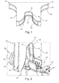
- Fig. 1 shows a crimp die 10 in accordance with the present invention in a three-dimensional, perspective view. All the illustrations of the enclosed figures are up-to-scale illustrations, whereby the different elements are shown enlarged for clarity reasons.
- the width e.g. from the outer edge of the left leg to the outer edge of the right leg
- the die is adapted to crimp terminals with an overall longitudinal length of maybe 20 to 50 mm.
- the crimp die 10 comprises first and second legs 12,14 which extend parallel to each other in the crimping direction.
- the skilled person will recognize that the "crimping direction" is the direction in which the die has to be moved for the crimping process.
- the two legs 12 and 14 define a curved crimping surface 16 therebetween.
- the crimping surface extends parallel to the longitudinal axis of the contact terminal to be crimped and will upon crimping come into contact with the crimping wings of the terminal and will thus bend the same in the desired crimp shape.
- the two crimping legs 12,14 define a u-shaped cross-section in a plane perpendicular to the longitudinal axis of the contact terminal to be crimped.
- the skilled person will recognize that with this type of crimp die comprising two crimping legs defining u-shaped cross-section, any contact terminal will extend perpendicular to the main plate of the crimp die 10.
- the crimping surface 16 comprises an enlarged entrance portion 18, which is achieved by the particular shape of the first and the second legs 12,14. This entrance portion 18 facilitates the introduction of the corresponding crimping wings of a contact terminal.
- the entrance portion 18 narrows to offer an essentially funnel shape up to the bottom portion 20.
- the width (as seen in longitudinal direction of the contact terminal to be crimped when arranged in the crimping position) of the crimping surface 16 is confined by two rims 22 and 24, which protrude in crimping direction.
- the crimp die 10 is assembled from essentially three steel plates, a first plate 30 forming the crimping surface 16 and the second 32 and third 34 plates providing each a rim 22, respectively 24 protruding in crimping direction.
- the second and third plates 32 and 34 are arranged on opposite main sides of the first plate 30 and are in contact with said main sides of the first plate.
- the three plates can for example be mounted in a corresponding crimping apparatus and clamped therein in the configuration shown in the figures.
- the three plates may be firmly attached to each other, for example by welding or by suitable fastening means such as screw and nut means or similar.
- the crimp die as shown in Fig. 1 could likewise be provided in form of one integral metal part, the shown configuration made of three plates is preferred, since the manufacturing of three separate plates as shown is more cost efficient than the manufacturing of one single integrated part.
- the two rims 22 and 24 have a rounded surface, and second and third plate each have a contour, which is essentially identical to the contour of the first plate.
- FIG. 2 the use of the crimp die is explained in more detail.
- the crimp die 10 of Figure 1 and a corresponding crimp anvil 11.
- Anvil and crimp die are for example mounted in a suitable crimping apparatus, as they are generally known to the skilled person.
- Onto the crimp anvil 11 a contact terminal 40 is arranged.
- the contact terminal 40 comprises a spring cage 42 for the reception of a corresponding contact pin of another contact terminal.
- the contact terminal comprises a first pair of crimping wings 43, which serve for the mechanical and electrical connection of the contact terminal with the stripped wire 57 of an electrical cable 50.
- the contact terminal 40 comprises a second pair of crimping wings, namely so called insulating or seal crimping wings 44.
- the wire crimping wings 43 serve in particular for the establishing of an electrical connection with the cable 50
- the insulating or seal crimping wings 44 are mainly provided for a firm mechanical connection of the contact terminal 40 with the cable 50.
- the electrical cable 50 comprises a cable insulation 52 and a number of cable wires 57.
- the cable insulation 52 is removed at the free end of the cable 50 to allow en electrical connection with the wires 57 by means of the wire crimping wings 43.
- a single wire seal 54 is provided over the insulation 52 of the cable.
- the insulating or seal crimping wings 44 are crimped around a seal crimp portion 56 of the single wire seal 54.
- the two protruding rims and the crimping surface 16 form a groove, which is dimensioned respectively adapted for the reception of the crimping wings 44 of the contact terminal 40.
- the crimping surface 16 has a width, as seen in the direction of the longitudinal axis of the contact terminal to be crimped, which is slightly larger than the corresponding width of the crimping wings 44. From Fig. 2 one can also derive, that the crimping surface 16 extends in a direction parallel to the longitudinal axis of terminal 40.
- the protruding rims 22 and 24 are provided over essentially the whole inner length of the crimping legs including the bottom portion 20.
- This configuration is preferred, although for the positive effects of the invention it is sufficient that protruding rims exist in the area of the bottom portion 20 of the crimp die 10.
- the protruding rims are not strictly necessary. The reason for that is, that the rims at the entrance portion 18 will not come into contact with the surfaces of the insulation, respectively the sealing member upon crimping.
- the portion of the rims 24 and 22 at or near the bottom portion 20, which provide the advantageous disposition of the material of the insulation or the sealing member and which reduces the risks that the edges of the crimping wings 44 cut into the surface of the insulation or the sealing member.
- the crimp die 10 i.e. the crimping surface 16
- the two crimping wings 44 will roll inwardly and bend over the seal crimp portion 56 of the single wire seal 54.
- the protruding rims 22 and 24 will dispose the material of the single wire seal 54 likewise downwardly, i.e.
- the disposition of the material of the single wire seal 54 is in the range of a millimeter or a fraction of a millimeter only. However, such a small displacement is sufficient to prevent the edges of the crimping wings 44 from cutting into the material of the single wire seal, respectively the cable insulation 52.
- Fig. 3 shows a detail of the configuration of Fig. 2 seen from the opposite side. In Fig. 3 , one can clearly see the sealing lips 55 of the single wire seal 54 as well as the seal crimp portion 56 thereof.
- Fig. 4 a side view is shown of the process shown in Figs. 2 and 3.
- Fig. 4 shows that the width of the crimping surface 16 as seen in the direction of the longitudinal axis of the contact terminal is slightly larger than the width of the crimping wings 44. Further, one can see from this illustration how the crimping surface 16 is confined in this direction by the two rims 22 and 24.
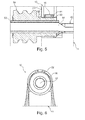
- Fig. 5 shows a detail of the illustration of Fig. 4 in a cut view.
- the crimping wings 44 are bent into their final configuration.
- the two rims 22 and 24 slightly displace the material of the single wire seal 54 in the area of the crimping wings 44, so that the edges of the wings 44 do not cut into the surface of the seal 54.
- the material of the single wire seal 54 is resilient, the material will go back into the initial configuration as soon as the crimping die 10 is removed.
- a secure and firm fixation of the contact terminal 40 onto the cable insulation or single wire seal can be achieved, without the edges of the crimping wings 44 cutting into the soft material of the insulation or seal.
- Fig. 6 is a cross-sectional view taken along a cut A-A of Fig. 4 . From Fig. 6 it can be seen, how the crimping wings 44 are completely bent around the seal crimp portion 56 of the single wire seal 54. Since the rims 22 and 24 protrude in crimping direction relative to the crimping surface the soft material of the seal, respectively the insulation, is displaced during the end of the crimping process and thereby moved away from the edges of the crimping wings.
- Crimp die 10 Crimp anvil 11 Crimping legs 12, 14 Crimping surface 16 Entrance portion 18 Bottom portion 20 Protruding rims 22, 24 First plate 30 Second plate 32 Third plate 34 Contact terminal 40 Spring cage 42 Wire crimping wings 43 Insulation or seal crimping wings 44 Electrical Cable 50 Cable insulation 52 Single wire seal 54 Sealing lips 55 Seal crimping portion 56 Cable wires 57
Landscapes
- Engineering & Computer Science (AREA)
- Manufacturing & Machinery (AREA)
- Manufacturing Of Electrical Connectors (AREA)
- Connections Effected By Soldering, Adhesion, Or Permanent Deformation (AREA)
Abstract
Description
- The present invention relates to a crimp die for crimping a crimping portion of a contact terminal onto an electrical cable, in particular onto a single wire seal of an electrical cable.
- In order to mechanically and electrically couple electrical contact terminals to electrical cables, commonly contact terminals are provided with crimping wings, which can be crimped around the striped wires of the electrical cables as well as to the insulation of the cables. Commonly used terminals usually comprise a pair of wire crimping wings, which upon crimping are bent around a corresponding dismantled cable portion and another pair of insulating or sealing crimping wings, which upon crimping are bent around the insulating material of the electrical cable or around a cable or wire seal. In other words, upon crimping a contact terminal to the electrical cable, the insulation or sealing crimping wings are bent around a non-dismantled portion of the electrical cable, i.e. around the cable insulation and / or a sealing member such as a single wire seal, to establish a mechanical connection between the contact terminal and the cable.
- The crimping in industrial sized production processes is achieved by automated crimping apparatuses that comprise different crimp dies for the crimping of the wire crimping wings and the insulating or sealing crimping wings of the respective contact terminals. A typical prior art example of a crimping tool used for crimping a contact terminal to an electrical cable is described in document
US 5,415,015 . Therein, crimp dies are described which can be used for example in a hand crimp tool, i.e. a plier-like hand tool used for manually crimping of contact terminals to electrical cables. According to this document, the crimp dies comprise separate sections for crimping insulation crimping wings, for example to a cable insulation, and wire crimping wings for crimping onto the dismantled cable stands. The crimping method described therein results in insulation crimping wings, which are bent around a cable insulation in an essentially round shape and wire crimping wings, which are bent essentially forming a B-shape. - A further prior art example of crimp dies is described in document
EP 2 485 343 . In this document an attempt is described to overcome the problem that after crimping the contact terminals can get stuck in the crimping tools. For example, according to this document the crimped contact terminal can get stuck in the contour of the corresponding crimp die after crimping. To solve this problem, it is suggested to provide a crimping anvil with a particular opening angel and a correspondingly formed B-shaped crimp die to facilitate removal of the crimp contact terminals after crimping. - Yet a further prior art crimping tool for crimping an insulation crimping portion of a contact terminal to a cable insulation is described in document
DE 197 37 863 . According to this document, a round shape of the crimped insulation crimp wings is achieved making use of a crimp die with an essentially round shaped inner crimping surface. In order to avoid edges of the insulation crimping wings of the terminal to cut into the cable insulation, it is suggested to taper the free ends of the insulation crimping wings. - One problem of the prior art crimping processes and crimp dies used is that they tend to damage the cable insulation and / or the sealing arranged on the cable due to the edges of the crimped wings cutting into the respective material. While this is even desired for the crimping onto the dismantled cable strands, it is highly problematic with the crimping to the cable insulation or any sealing members, since the desired mechanical connection is weakened thereby. A further problem is that the commonly used material silicon for the single wire seals reacts very sensitively to tiny scratches or cuts. Even a small cut, as it typically occurs upon crimping of the crimping wings onto such a sealing member of silicon, increases highly the risk that the whole sealing member fails, if one applies pulling forces to the cable provided with the sealing member.
- In view of the above, it is an object of the present invention to provide a crimp die for crimping a crimping portion of a contact terminal onto an electrical cable, which overcomes the above problems and which in particular reduces the risk of damages to the cable insulation or any sealing member upon crimping of an electrical contact terminal to an electrical cable. It is a particular object of the present invention to provide a crimp die for crimping insulation or sealing crimping wings to a cable insulation or to a seal member such that the risk of damaging the insulation or sealing member due to the crimping wings is reduced.
- These and other objects which will become apparent upon reading the following description are solved by a crimp die according to claim 1.
- According to the invention, a crimp die is provided which is adapted for crimping a crimping portion of a contact terminal onto an electrical cable, which crimp die comprises two crimping legs extending parallel to each other in the crimping direction and defining a curved crimping surface there between. The width of the crimping surface as seen in the direction of the longitudinal axis of any contact terminal to be crimped is confined by at least two rims protruding in crimping direction. Thereby, upon using the crimp die, the two protruding rims can come e.g. into contact with the surface of the insulation or seal member depressing the elastic material to some extent during the actual crimping process, i.e. during the crimping of the crimping wings around the insulation or seal member. When the crimp die is removed after the crimping process is complete, the displaced material of the cable insulation or the seal member will resiliently spring back, so that a robust mechanical connection is achieved, whereby at the same time the surface of the cable insulation or seal member is not damaged by the edges of the crimping wings.
- The skilled person will understand that for the purposes of description herein at some instances relative orientations with regard to a contact terminal to be crimped are used, such as "as seen in the direction of the longitudinal axis of any contact terminal", without that the contact terminal necessarily forms part of the claimed invention.
- Preferably, the two crimping legs define a u-shaped cross-section in a plane perpendicular to the longitudinal axis of the contact terminal to be crimped, as it is also known for example from the above mentioned
EP 2 458 343 . The u-shape cross section facilitates the crimping process and in particular the reception of the terminal and cable to be crimped between the two crimping legs. - The crimp die can be made from one single integral part but it may also be assembled from several parts. In a preferred embodiment, the crimping legs are part of a first metal plate, which can for example be mounted to a corresponding crimping apparatus. The protruding rims are part of second and respective third metal plates, which can for example be arranged on opposite main sides of the first plate in a contacting arrangement, thereby sandwiching the first metal plate. Preferably, the second and third plates have a contour, which is essentially identical to the contour of the first plate, i.e. they also comprise for example two legs defining a u-shaped cross-section. However, as seen in crimping direction, the rims protrude to some extent further than the crimping surface. This has the advantageous effect, that upon using the crimp die of the invention, the protruding rims will come into contact with the insulation or sealing member of the electrical cable, thereby displacing the material to some extent during the crimping process. The use of second and third plates for providing the protruding rims allows the cost efficient manufacturing of the crimp die of the present invention, since the manufacturing of three relatively simple plates is simpler than the manufacturing of an integrated crimp die comprising corresponding protruding crimping rims.
- As it will become more apparent from considering the provided figures, the protruding rims and the crimping surface preferably form a groove. The groove is most preferably adapted for the reception of the corresponding crimping wings of the contact terminal to be crimped. In other words, when the electrical terminal is arranged in a corresponding crimping apparatus and the inventive crimp die is applied thereon, the crimping wings of the terminal are arranged between the two protruding rims. Preferably, the dimensions of the crimp die of the invention should be such that the protruding rims are as close as possible to the crimping wings of the terminal, when in use. Thereby, the material of the cable insulation or sealing member is effectively displaced in the proximity of the outer edges of the crimping wings of the terminal, whereby any risk for damages to the insulation or sealing is effectively reduced. Generally preferred, the protruding rims have a rounded surface to prevent any damages to the insulation or sealing member of the cable.
- The present invention also relates to a system for crimping a crimping portion of a contact terminal onto an electrical cable. As the skilled person will recognize, the above described inventive crimp die is intended to be used for crimping a contact terminal comprising wings onto an electrical cable, and in particular onto a cable insulation or a sealing member, such as a single wire seal provided on the electrical cable. Thus, the expression "to be crimped onto a cable" encompasses a direct as well as an indirect crimping onto the cable.
- The inventive crimp die can be used in automatic crimping apparatuses for large scale industrial crimping processes. To this end, the crimp die is provided for example as exchangeable part, which can be mounted to a corresponding crimping apparatus in an assembly line. However, the inventive crimp die may also be used in hand held crimp tools, as they are commonly used in workshops etc.
- A method for using the crimp die of the present invention for crimping a contact terminal onto an electrical cable comprises usually the steps of providing a crimping apparatus as mentioned above, which includes an inventive crimp die, for example mounted therein. Then, a contact terminal comprising crimping wings as they are commonly known for example from the initially discussed prior art documents is provided in the crimping apparatus. Thereafter, or at the same time, an electrical cable is arranged in or onto the contact terminal, such that the crimping wings of the terminal are disposed in the desired relation to the electrical cable, respectively any sealing provided on the cable. Preferably, a single wire seal is likewise provided on the cable, either before or after arranging the cable onto the contact terminal. Finally, the crimping wings of the contact terminals are crimped by means of the inventive crimp die on to said single wire seal respectively onto for example the cable insulation. Due to the protruding rims being arranged on both sides of the crimping surface (as seen in the direction of the longitudinal axis of the contact terminal to be crimped), the rims will displace the material of the sealing or cable insulation to some extent, such that it is not damaged by the sharp edges of the crimping wings upon closing of the crimp.
- In the following, the invention is described exemplarily with reference to the enclosed figures, in which:
- Fig 1
- shows a three-dimensional illustration of a crimp die in accordance with the present invention;
- Fig. 2
- shows a three-dimensional view of the crimping process utilizing the crimp die of
Fig. 1 ; - Fig.3
- shows a detail of the illustration of
Fig. 2 seen from a different perspective; - Fig. 4
- is a schematic side view of the illustration of
Fig. 2 ; - Fig. 5
- is a side cross-sectional view of a detail of
Fig. 4 ; and - Fig.6
- is a cross-sectional schematic view of a detail of
Fig. 4 taken along a plane at A-A. -
Fig. 1 shows a crimp die 10 in accordance with the present invention in a three-dimensional, perspective view. All the illustrations of the enclosed figures are up-to-scale illustrations, whereby the different elements are shown enlarged for clarity reasons. In practice, the width (e.g. from the outer edge of the left leg to the outer edge of the right leg) for example of the crimp die 10 ofFig. 1 is in the range of 15 to 20 mm and the die is adapted to crimp terminals with an overall longitudinal length of maybe 20 to 50 mm. - As one can tell from
Fig. 1 , the crimp die 10 comprises first andsecond legs legs surface 16 therebetween. The crimping surface extends parallel to the longitudinal axis of the contact terminal to be crimped and will upon crimping come into contact with the crimping wings of the terminal and will thus bend the same in the desired crimp shape. As it is common in the art, the two crimpinglegs surface 16 comprises anenlarged entrance portion 18, which is achieved by the particular shape of the first and thesecond legs entrance portion 18 facilitates the introduction of the corresponding crimping wings of a contact terminal. Theentrance portion 18 narrows to offer an essentially funnel shape up to thebottom portion 20. As it can be seen fromFigure 1 , the width (as seen in longitudinal direction of the contact terminal to be crimped when arranged in the crimping position) of the crimpingsurface 16 is confined by tworims - In the embodiment shown in the figures, the crimp die 10 is assembled from essentially three steel plates, a
first plate 30 forming the crimpingsurface 16 and the second 32 and third 34 plates providing each arim 22, respectively 24 protruding in crimping direction. The second andthird plates first plate 30 and are in contact with said main sides of the first plate. When in use, the three plates can for example be mounted in a corresponding crimping apparatus and clamped therein in the configuration shown in the figures. Alternatively, the three plates may be firmly attached to each other, for example by welding or by suitable fastening means such as screw and nut means or similar. Although the crimp die as shown inFig. 1 could likewise be provided in form of one integral metal part, the shown configuration made of three plates is preferred, since the manufacturing of three separate plates as shown is more cost efficient than the manufacturing of one single integrated part. - As one can further derive from the figures, the two
rims Fig. 1 , automatically the desired shape results, whereby in particular the protruding rims and the crimpingsurface 16 from a groove adapted to receive the crimping wings of a terminal. The expression "rims protruding in crimping direction" in the present case means relative to the crimping surface. As will be explained in more detail below, thereby the soft material of the cable insulation or any single wire seal can be protected from being damaged by the crimping wings of an electrical contact terminal. The groove shape can best be seen inFig. 5 . - Turning now to
Fig. 2 , the use of the crimp die is explained in more detail. InFigure 2 , one can see the crimp die 10 ofFigure 1 and acorresponding crimp anvil 11. Anvil and crimp die are for example mounted in a suitable crimping apparatus, as they are generally known to the skilled person. Onto the crimp anvil 11 acontact terminal 40 is arranged. Thecontact terminal 40 comprises aspring cage 42 for the reception of a corresponding contact pin of another contact terminal. In the shown example, the contact terminal comprises a first pair of crimpingwings 43, which serve for the mechanical and electrical connection of the contact terminal with the strippedwire 57 of anelectrical cable 50. In addition thereto, thecontact terminal 40 comprises a second pair of crimping wings, namely so called insulating orseal crimping wings 44. While thewire crimping wings 43 serve in particular for the establishing of an electrical connection with thecable 50, the insulating orseal crimping wings 44 are mainly provided for a firm mechanical connection of thecontact terminal 40 with thecable 50. Theelectrical cable 50 comprises acable insulation 52 and a number ofcable wires 57. Thecable insulation 52 is removed at the free end of thecable 50 to allow en electrical connection with thewires 57 by means of thewire crimping wings 43. Additionally, in the shown configuration, asingle wire seal 54 is provided over theinsulation 52 of the cable. The insulating orseal crimping wings 44 are crimped around aseal crimp portion 56 of thesingle wire seal 54. - From
Fig. 2 and3 one can clearly see that the two protruding rims and the crimpingsurface 16 form a groove, which is dimensioned respectively adapted for the reception of the crimpingwings 44 of thecontact terminal 40. In other words, the crimpingsurface 16 has a width, as seen in the direction of the longitudinal axis of the contact terminal to be crimped, which is slightly larger than the corresponding width of the crimpingwings 44. FromFig. 2 one can also derive, that the crimpingsurface 16 extends in a direction parallel to the longitudinal axis ofterminal 40. - Turning back to
Fig. 1 , one can see that the protrudingrims bottom portion 20. This configuration is preferred, although for the positive effects of the invention it is sufficient that protruding rims exist in the area of thebottom portion 20 of the crimp die 10. In particular at theentrance portion 18 of the crimp die 10 the protruding rims are not strictly necessary. The reason for that is, that the rims at theentrance portion 18 will not come into contact with the surfaces of the insulation, respectively the sealing member upon crimping. It is in particular the portion of therims bottom portion 20, which provide the advantageous disposition of the material of the insulation or the sealing member and which reduces the risks that the edges of the crimpingwings 44 cut into the surface of the insulation or the sealing member. - In the position shown in
Figure 2 , the crimp die 10, i.e. the crimpingsurface 16, is in contact with the free ends of the crimpingwings 44, but the actual crimping process has not yet started. The skilled person will recognize that upon movement of the crimp die 10 into the crimping direction, i.e. downwards inFig. 2 , the two crimpingwings 44 will roll inwardly and bend over theseal crimp portion 56 of thesingle wire seal 54. At the end of the crimping process, when the crimpingwings 44 are almost bent into their final position, the protrudingrims single wire seal 54 likewise downwardly, i.e. away from the edges of the crimpingwings 44, thereby protecting thesingle wire seal 54 from damages. It should be noted that in practice, the disposition of the material of thesingle wire seal 54 is in the range of a millimeter or a fraction of a millimeter only. However, such a small displacement is sufficient to prevent the edges of the crimpingwings 44 from cutting into the material of the single wire seal, respectively thecable insulation 52. -
Fig. 3 shows a detail of the configuration ofFig. 2 seen from the opposite side. InFig. 3 , one can clearly see the sealing lips 55 of thesingle wire seal 54 as well as theseal crimp portion 56 thereof. - In
Fig. 4 , a side view is shown of the process shown inFigs. 2 and3. Fig. 4 shows that the width of the crimpingsurface 16 as seen in the direction of the longitudinal axis of the contact terminal is slightly larger than the width of the crimpingwings 44. Further, one can see from this illustration how the crimpingsurface 16 is confined in this direction by the tworims -
Fig. 5 shows a detail of the illustration ofFig. 4 in a cut view. In this view the crimpingwings 44 are bent into their final configuration. As one can see fromFig. 5 , the tworims single wire seal 54 in the area of the crimpingwings 44, so that the edges of thewings 44 do not cut into the surface of theseal 54. To this end, it is advantageous that therims wings 44. Since the material of thesingle wire seal 54, respectively of thecable insulation 52 if no seal is provided, is resilient, the material will go back into the initial configuration as soon as the crimpingdie 10 is removed. Thus, a secure and firm fixation of thecontact terminal 40 onto the cable insulation or single wire seal can be achieved, without the edges of the crimpingwings 44 cutting into the soft material of the insulation or seal. -
Fig. 6 is a cross-sectional view taken along a cut A-A ofFig. 4 . FromFig. 6 it can be seen, how the crimpingwings 44 are completely bent around theseal crimp portion 56 of thesingle wire seal 54. Since therims List of reference numbers: Crimp die 10 Crimp anvil 11 Crimping legs 12, 14 Crimping surface 16 Entrance portion 18 Bottom portion 20 Protruding rims 22, 24 First plate 30 Second plate 32 Third plate 34 Contact terminal 40 Spring cage 42 Wire crimping wings 43 Insulation or seal crimping wings 44 Electrical Cable 50 Cable insulation 52 Single wire seal 54 Sealing lips 55 Seal crimping portion 56 Cable wires 57
Claims (13)
- Crimp die (10), adapted for crimping a crimping portion of a contact terminal onto an electrical cable, which crimp die (10) comprises two crimping legs (12, 4) extending in the crimping direction and defining a curved crimping surface (16) therebetween, characterized in that the width of the crimping surface (16) as seen in the direction of the longitudinal axis of the contact terminal to be crimped is confined by at least two rims (22, 24) protruding in crimping direction.
- Crimp die in accordance with claim 1, characterized in that the two crimping legs (12,14) define a u-shaped cross-section in a plane perpendicular to the longitudinal axis of the contact terminal to be crimped.
- Crimp die in accordance with claims 1 or 2, characterized in that the crimping legs (12,14) are part of a first metal plate (30) and the rims are part of second (32) and respective third (34) metal plates.
- Crimp die in accordance with claim 3, characterized in that the second (32) and third (34) plates are arranged on opposite main sides of the first plate (30) and being in contact with said respective main sides of the first plate.
- Crimp die in accordance with any of the preceding claims 3 or 4, characterized in that the second (32) and third (34) plates have a contour essentially identical to the contour of the first plate (30).
- Crimp die in accordance with any of the preceding claims, characterized in that the protruding rims (22, 24) and the crimping surface (16) form a groove.
- Crimp die in accordance with any of the preceding claims, characterized in that the protruding rims (12, 4) and crimping surface (16) form a groove adapted for the reception of crimping wings of a contact terminal.
- Crimp die in accordance with any of the preceding claims, characterized in that the protruding rims (12, 4) have a rounded surface.
- Crimp die in accordance with any of the preceding claims, characterized in that the crimping surface (16) extends in a direction parallel to the longitudinal axis of the terminal.
- Crimp die in accordance with any of the preceding claims, characterized in that the protruding rims (12, 4) are provided over essentially the whole inner lengths of the crimping legs.
- System for crimping a crimping portion of a contact terminal onto an electrical cable, comprising a crimp die (10) in accordance with any of the preceding claims, an electrical cable (50) and at least one contact terminal (40) comprising crimping wings (44) to be crimped onto the electrical cable.
- Crimping apparatus for crimping a crimping portion of a contact terminal onto an electrical cable (50) comprising at least one crimp die (10) according to any one of the preceding claims 1 to 10.
- Method for crimping a contact terminal onto an electrical cable, comprising the steps of:- providing a crimping apparatus in accordance with claim 12;- providing a contact terminal (40) comprising crimping wings (44);- providing an electrical cable (50);- arranging the cable (50) onto the contact terminal (40);- arranging a single wire seal (54) onto the cable (50);- crimping the crimping wings (44) of the contact terminal (40) by means of the crimp die (10) onto the single wire seal.
Priority Applications (1)
| Application Number | Priority Date | Filing Date | Title |
|---|---|---|---|
| EP13163361.2A EP2790278B1 (en) | 2013-04-11 | 2013-04-11 | Crimp die |
Applications Claiming Priority (1)
| Application Number | Priority Date | Filing Date | Title |
|---|---|---|---|
| EP13163361.2A EP2790278B1 (en) | 2013-04-11 | 2013-04-11 | Crimp die |
Publications (2)
| Publication Number | Publication Date |
|---|---|
| EP2790278A1 true EP2790278A1 (en) | 2014-10-15 |
| EP2790278B1 EP2790278B1 (en) | 2017-09-27 |
Family
ID=48095664
Family Applications (1)
| Application Number | Title | Priority Date | Filing Date |
|---|---|---|---|
| EP13163361.2A Active EP2790278B1 (en) | 2013-04-11 | 2013-04-11 | Crimp die |
Country Status (1)
| Country | Link |
|---|---|
| EP (1) | EP2790278B1 (en) |
Citations (8)
| Publication number | Priority date | Publication date | Assignee | Title |
|---|---|---|---|---|
| US3241098A (en) * | 1965-04-02 | 1966-03-15 | Amp Inc | Pre-insulated electrical connector and dies for applying same |
| FR2574994A1 (en) * | 1984-12-14 | 1986-06-20 | Electricite De France | Device enabling a junction connection for electrical conductors to be produced |
| CH681836A5 (en) * | 1990-11-09 | 1993-05-28 | Ulrich Blecher | Crimping tool with crimper and cooperating anvil - with cooperating crimping profiles having three=dimensional curvature obtained via depth erosion process. |
| US5415015A (en) | 1993-10-14 | 1995-05-16 | Molex Incorporated | Electrical terminal crimping tool |
| DE19737863A1 (en) | 1997-08-29 | 1999-03-04 | Whitaker Corp | Crimped electrical connector for contacting electrical conductor |
| WO2009115860A1 (en) * | 2008-03-20 | 2009-09-24 | Fci | Electric terminal crimping method and assembly obtained |
| EP2458343A1 (en) | 2009-07-21 | 2012-05-30 | Nippon Seiki Co., Ltd. | Instrument drive device |
| EP2485343A1 (en) | 2011-02-02 | 2012-08-08 | Wezag GmbH Werkzeugfabrik | B-crimp die |
-
2013
- 2013-04-11 EP EP13163361.2A patent/EP2790278B1/en active Active
Patent Citations (8)
| Publication number | Priority date | Publication date | Assignee | Title |
|---|---|---|---|---|
| US3241098A (en) * | 1965-04-02 | 1966-03-15 | Amp Inc | Pre-insulated electrical connector and dies for applying same |
| FR2574994A1 (en) * | 1984-12-14 | 1986-06-20 | Electricite De France | Device enabling a junction connection for electrical conductors to be produced |
| CH681836A5 (en) * | 1990-11-09 | 1993-05-28 | Ulrich Blecher | Crimping tool with crimper and cooperating anvil - with cooperating crimping profiles having three=dimensional curvature obtained via depth erosion process. |
| US5415015A (en) | 1993-10-14 | 1995-05-16 | Molex Incorporated | Electrical terminal crimping tool |
| DE19737863A1 (en) | 1997-08-29 | 1999-03-04 | Whitaker Corp | Crimped electrical connector for contacting electrical conductor |
| WO2009115860A1 (en) * | 2008-03-20 | 2009-09-24 | Fci | Electric terminal crimping method and assembly obtained |
| EP2458343A1 (en) | 2009-07-21 | 2012-05-30 | Nippon Seiki Co., Ltd. | Instrument drive device |
| EP2485343A1 (en) | 2011-02-02 | 2012-08-08 | Wezag GmbH Werkzeugfabrik | B-crimp die |
Also Published As
| Publication number | Publication date |
|---|---|
| EP2790278B1 (en) | 2017-09-27 |
Similar Documents
| Publication | Publication Date | Title |
|---|---|---|
| JP6954170B2 (en) | Terminal | |
| US9853368B2 (en) | Electrical crimp terminal | |
| JP6939625B2 (en) | Terminals and wires with terminals | |
| CA2933670C (en) | Cable compression die assembly for crimp connections | |
| US9768526B2 (en) | Crimp-connection structural body, wire harness, method of manufacturing crimp-connection structural body, and device of manufacturing crimp-connection structural body | |
| EP2999051A1 (en) | Wire with terminal | |
| EP2290747A1 (en) | Metal terminal fitting and electric wire with terminal | |
| US6626711B2 (en) | Press-clamping terminal and method of examining press-clamped condition thereof | |
| US10424849B2 (en) | Crimp connection system for electrical cables comprising a fastening sleeve | |
| US10276283B2 (en) | Manufacturing method for terminal-equipped electric wire | |
| US10886686B2 (en) | Method for crimping an electrical contact to a cable and tool for implementing said method | |
| US9882289B2 (en) | Sheet metal part with improved connection tab geometry | |
| US4442316A (en) | Crimp connector for electrical wires | |
| EP2919324A1 (en) | Contact element and contact arrangement with front protection and method of producing the latter | |
| EP3579342A1 (en) | Multiple bussed terminations | |
| US5084963A (en) | Preconnection deforming die and method of connecting a grounding rod with an electrical cable | |
| US9088079B2 (en) | Crimped terminal attached electric wire and method of crimping crimped terminal to electric wire | |
| CN109565140B (en) | Crimping tool and terminals obtained using the crimping tool | |
| US20180138600A1 (en) | Terminal and terminal-equipped electric wire | |
| US20230275383A1 (en) | Decagon compression die | |
| EP2790278B1 (en) | Crimp die | |
| JP6786312B2 (en) | Crimping terminal | |
| US7931487B1 (en) | Electrical terminal connector and method of connection | |
| EP2793326B1 (en) | Insulation or sealing crimp die | |
| KR200493248Y1 (en) | Electrical Wiring Box for Wire Connection |
Legal Events
| Date | Code | Title | Description |
|---|---|---|---|
| PUAI | Public reference made under article 153(3) epc to a published international application that has entered the european phase |
Free format text: ORIGINAL CODE: 0009012 |
|
| 17P | Request for examination filed |
Effective date: 20130411 |
|
| AK | Designated contracting states |
Kind code of ref document: A1 Designated state(s): AL AT BE BG CH CY CZ DE DK EE ES FI FR GB GR HR HU IE IS IT LI LT LU LV MC MK MT NL NO PL PT RO RS SE SI SK SM TR |
|
| AX | Request for extension of the european patent |
Extension state: BA ME |
|
| R17P | Request for examination filed (corrected) |
Effective date: 20150415 |
|
| RBV | Designated contracting states (corrected) |
Designated state(s): AL AT BE BG CH CY CZ DE DK EE ES FI FR GB GR HR HU IE IS IT LI LT LU LV MC MK MT NL NO PL PT RO RS SE SI SK SM TR |
|
| GRAP | Despatch of communication of intention to grant a patent |
Free format text: ORIGINAL CODE: EPIDOSNIGR1 |
|
| RIC1 | Information provided on ipc code assigned before grant |
Ipc: H01R 43/058 20060101AFI20170310BHEP Ipc: H01R 4/18 20060101ALN20170310BHEP |
|
| RIC1 | Information provided on ipc code assigned before grant |
Ipc: H01R 43/058 20060101AFI20170329BHEP Ipc: H01R 4/18 20060101ALN20170329BHEP |
|
| INTG | Intention to grant announced |
Effective date: 20170418 |
|
| GRAS | Grant fee paid |
Free format text: ORIGINAL CODE: EPIDOSNIGR3 |
|
| GRAA | (expected) grant |
Free format text: ORIGINAL CODE: 0009210 |
|
| AK | Designated contracting states |
Kind code of ref document: B1 Designated state(s): AL AT BE BG CH CY CZ DE DK EE ES FI FR GB GR HR HU IE IS IT LI LT LU LV MC MK MT NL NO PL PT RO RS SE SI SK SM TR |
|
| REG | Reference to a national code |
Ref country code: GB Ref legal event code: FG4D |
|
| REG | Reference to a national code |
Ref country code: CH Ref legal event code: EP |
|
| REG | Reference to a national code |
Ref country code: AT Ref legal event code: REF Ref document number: 932835 Country of ref document: AT Kind code of ref document: T Effective date: 20171015 |
|
| REG | Reference to a national code |
Ref country code: IE Ref legal event code: FG4D |
|
| REG | Reference to a national code |
Ref country code: DE Ref legal event code: R096 Ref document number: 602013027046 Country of ref document: DE |
|
| PG25 | Lapsed in a contracting state [announced via postgrant information from national office to epo] |
Ref country code: SE Free format text: LAPSE BECAUSE OF FAILURE TO SUBMIT A TRANSLATION OF THE DESCRIPTION OR TO PAY THE FEE WITHIN THE PRESCRIBED TIME-LIMIT Effective date: 20170927 Ref country code: NO Free format text: LAPSE BECAUSE OF FAILURE TO SUBMIT A TRANSLATION OF THE DESCRIPTION OR TO PAY THE FEE WITHIN THE PRESCRIBED TIME-LIMIT Effective date: 20171227 Ref country code: FI Free format text: LAPSE BECAUSE OF FAILURE TO SUBMIT A TRANSLATION OF THE DESCRIPTION OR TO PAY THE FEE WITHIN THE PRESCRIBED TIME-LIMIT Effective date: 20170927 Ref country code: LT Free format text: LAPSE BECAUSE OF FAILURE TO SUBMIT A TRANSLATION OF THE DESCRIPTION OR TO PAY THE FEE WITHIN THE PRESCRIBED TIME-LIMIT Effective date: 20170927 Ref country code: HR Free format text: LAPSE BECAUSE OF FAILURE TO SUBMIT A TRANSLATION OF THE DESCRIPTION OR TO PAY THE FEE WITHIN THE PRESCRIBED TIME-LIMIT Effective date: 20170927 |
|
| REG | Reference to a national code |
Ref country code: NL Ref legal event code: MP Effective date: 20170927 |
|
| REG | Reference to a national code |
Ref country code: LT Ref legal event code: MG4D |
|
| REG | Reference to a national code |
Ref country code: AT Ref legal event code: MK05 Ref document number: 932835 Country of ref document: AT Kind code of ref document: T Effective date: 20170927 |
|
| PG25 | Lapsed in a contracting state [announced via postgrant information from national office to epo] |
Ref country code: GR Free format text: LAPSE BECAUSE OF FAILURE TO SUBMIT A TRANSLATION OF THE DESCRIPTION OR TO PAY THE FEE WITHIN THE PRESCRIBED TIME-LIMIT Effective date: 20171228 Ref country code: BG Free format text: LAPSE BECAUSE OF FAILURE TO SUBMIT A TRANSLATION OF THE DESCRIPTION OR TO PAY THE FEE WITHIN THE PRESCRIBED TIME-LIMIT Effective date: 20171227 Ref country code: RS Free format text: LAPSE BECAUSE OF FAILURE TO SUBMIT A TRANSLATION OF THE DESCRIPTION OR TO PAY THE FEE WITHIN THE PRESCRIBED TIME-LIMIT Effective date: 20170927 Ref country code: LV Free format text: LAPSE BECAUSE OF FAILURE TO SUBMIT A TRANSLATION OF THE DESCRIPTION OR TO PAY THE FEE WITHIN THE PRESCRIBED TIME-LIMIT Effective date: 20170927 |
|
| PG25 | Lapsed in a contracting state [announced via postgrant information from national office to epo] |
Ref country code: NL Free format text: LAPSE BECAUSE OF FAILURE TO SUBMIT A TRANSLATION OF THE DESCRIPTION OR TO PAY THE FEE WITHIN THE PRESCRIBED TIME-LIMIT Effective date: 20170927 |
|
| REG | Reference to a national code |
Ref country code: FR Ref legal event code: PLFP Year of fee payment: 6 |
|
| PG25 | Lapsed in a contracting state [announced via postgrant information from national office to epo] |
Ref country code: ES Free format text: LAPSE BECAUSE OF FAILURE TO SUBMIT A TRANSLATION OF THE DESCRIPTION OR TO PAY THE FEE WITHIN THE PRESCRIBED TIME-LIMIT Effective date: 20170927 Ref country code: CZ Free format text: LAPSE BECAUSE OF FAILURE TO SUBMIT A TRANSLATION OF THE DESCRIPTION OR TO PAY THE FEE WITHIN THE PRESCRIBED TIME-LIMIT Effective date: 20170927 Ref country code: RO Free format text: LAPSE BECAUSE OF FAILURE TO SUBMIT A TRANSLATION OF THE DESCRIPTION OR TO PAY THE FEE WITHIN THE PRESCRIBED TIME-LIMIT Effective date: 20170927 |
|
| PG25 | Lapsed in a contracting state [announced via postgrant information from national office to epo] |
Ref country code: SK Free format text: LAPSE BECAUSE OF FAILURE TO SUBMIT A TRANSLATION OF THE DESCRIPTION OR TO PAY THE FEE WITHIN THE PRESCRIBED TIME-LIMIT Effective date: 20170927 Ref country code: AT Free format text: LAPSE BECAUSE OF FAILURE TO SUBMIT A TRANSLATION OF THE DESCRIPTION OR TO PAY THE FEE WITHIN THE PRESCRIBED TIME-LIMIT Effective date: 20170927 Ref country code: IT Free format text: LAPSE BECAUSE OF FAILURE TO SUBMIT A TRANSLATION OF THE DESCRIPTION OR TO PAY THE FEE WITHIN THE PRESCRIBED TIME-LIMIT Effective date: 20170927 Ref country code: EE Free format text: LAPSE BECAUSE OF FAILURE TO SUBMIT A TRANSLATION OF THE DESCRIPTION OR TO PAY THE FEE WITHIN THE PRESCRIBED TIME-LIMIT Effective date: 20170927 Ref country code: IS Free format text: LAPSE BECAUSE OF FAILURE TO SUBMIT A TRANSLATION OF THE DESCRIPTION OR TO PAY THE FEE WITHIN THE PRESCRIBED TIME-LIMIT Effective date: 20180127 Ref country code: SM Free format text: LAPSE BECAUSE OF FAILURE TO SUBMIT A TRANSLATION OF THE DESCRIPTION OR TO PAY THE FEE WITHIN THE PRESCRIBED TIME-LIMIT Effective date: 20170927 |
|
| REG | Reference to a national code |
Ref country code: DE Ref legal event code: R097 Ref document number: 602013027046 Country of ref document: DE |
|
| PG25 | Lapsed in a contracting state [announced via postgrant information from national office to epo] |
Ref country code: DK Free format text: LAPSE BECAUSE OF FAILURE TO SUBMIT A TRANSLATION OF THE DESCRIPTION OR TO PAY THE FEE WITHIN THE PRESCRIBED TIME-LIMIT Effective date: 20170927 |
|
| PLBE | No opposition filed within time limit |
Free format text: ORIGINAL CODE: 0009261 |
|
| STAA | Information on the status of an ep patent application or granted ep patent |
Free format text: STATUS: NO OPPOSITION FILED WITHIN TIME LIMIT |
|
| PG25 | Lapsed in a contracting state [announced via postgrant information from national office to epo] |
Ref country code: PL Free format text: LAPSE BECAUSE OF FAILURE TO SUBMIT A TRANSLATION OF THE DESCRIPTION OR TO PAY THE FEE WITHIN THE PRESCRIBED TIME-LIMIT Effective date: 20170927 |
|
| 26N | No opposition filed |
Effective date: 20180628 |
|
| PG25 | Lapsed in a contracting state [announced via postgrant information from national office to epo] |
Ref country code: MC Free format text: LAPSE BECAUSE OF FAILURE TO SUBMIT A TRANSLATION OF THE DESCRIPTION OR TO PAY THE FEE WITHIN THE PRESCRIBED TIME-LIMIT Effective date: 20170927 Ref country code: SI Free format text: LAPSE BECAUSE OF FAILURE TO SUBMIT A TRANSLATION OF THE DESCRIPTION OR TO PAY THE FEE WITHIN THE PRESCRIBED TIME-LIMIT Effective date: 20170927 |
|
| REG | Reference to a national code |
Ref country code: CH Ref legal event code: PL |
|
| REG | Reference to a national code |
Ref country code: DE Ref legal event code: R081 Ref document number: 602013027046 Country of ref document: DE Owner name: APTIV TECHNOLOGIES LIMITED, BB Free format text: FORMER OWNER: DELPHI INTERNATIONAL OPERATIONS LUXEMBOURG S.A R.L., BASCHARAGE, LU |
|
| REG | Reference to a national code |
Ref country code: BE Ref legal event code: MM Effective date: 20180430 |
|
| REG | Reference to a national code |
Ref country code: GB Ref legal event code: 732E Free format text: REGISTERED BETWEEN 20181213 AND 20181219 |
|
| REG | Reference to a national code |
Ref country code: IE Ref legal event code: MM4A |
|
| PG25 | Lapsed in a contracting state [announced via postgrant information from national office to epo] |
Ref country code: LU Free format text: LAPSE BECAUSE OF NON-PAYMENT OF DUE FEES Effective date: 20180411 |
|
| PG25 | Lapsed in a contracting state [announced via postgrant information from national office to epo] |
Ref country code: LI Free format text: LAPSE BECAUSE OF NON-PAYMENT OF DUE FEES Effective date: 20180430 Ref country code: CH Free format text: LAPSE BECAUSE OF NON-PAYMENT OF DUE FEES Effective date: 20180430 Ref country code: BE Free format text: LAPSE BECAUSE OF NON-PAYMENT OF DUE FEES Effective date: 20180430 |
|
| PG25 | Lapsed in a contracting state [announced via postgrant information from national office to epo] |
Ref country code: IE Free format text: LAPSE BECAUSE OF NON-PAYMENT OF DUE FEES Effective date: 20180411 |
|
| PG25 | Lapsed in a contracting state [announced via postgrant information from national office to epo] |
Ref country code: MT Free format text: LAPSE BECAUSE OF NON-PAYMENT OF DUE FEES Effective date: 20180411 |
|
| PG25 | Lapsed in a contracting state [announced via postgrant information from national office to epo] |
Ref country code: TR Free format text: LAPSE BECAUSE OF FAILURE TO SUBMIT A TRANSLATION OF THE DESCRIPTION OR TO PAY THE FEE WITHIN THE PRESCRIBED TIME-LIMIT Effective date: 20170927 |
|
| PG25 | Lapsed in a contracting state [announced via postgrant information from national office to epo] |
Ref country code: HU Free format text: LAPSE BECAUSE OF FAILURE TO SUBMIT A TRANSLATION OF THE DESCRIPTION OR TO PAY THE FEE WITHIN THE PRESCRIBED TIME-LIMIT; INVALID AB INITIO Effective date: 20130411 Ref country code: PT Free format text: LAPSE BECAUSE OF FAILURE TO SUBMIT A TRANSLATION OF THE DESCRIPTION OR TO PAY THE FEE WITHIN THE PRESCRIBED TIME-LIMIT Effective date: 20170927 |
|
| PG25 | Lapsed in a contracting state [announced via postgrant information from national office to epo] |
Ref country code: CY Free format text: LAPSE BECAUSE OF FAILURE TO SUBMIT A TRANSLATION OF THE DESCRIPTION OR TO PAY THE FEE WITHIN THE PRESCRIBED TIME-LIMIT Effective date: 20170927 Ref country code: MK Free format text: LAPSE BECAUSE OF NON-PAYMENT OF DUE FEES Effective date: 20170927 |
|
| PG25 | Lapsed in a contracting state [announced via postgrant information from national office to epo] |
Ref country code: AL Free format text: LAPSE BECAUSE OF FAILURE TO SUBMIT A TRANSLATION OF THE DESCRIPTION OR TO PAY THE FEE WITHIN THE PRESCRIBED TIME-LIMIT Effective date: 20170927 |
|
| P01 | Opt-out of the competence of the unified patent court (upc) registered |
Effective date: 20230425 |
|
| REG | Reference to a national code |
Ref country code: DE Ref legal event code: R081 Ref document number: 602013027046 Country of ref document: DE Owner name: APTIV TECHNOLOGIES AG, CH Free format text: FORMER OWNER: APTIV TECHNOLOGIES LIMITED, ST. MICHAEL, BB |
|
| PGFP | Annual fee paid to national office [announced via postgrant information from national office to epo] |
Ref country code: DE Payment date: 20250313 Year of fee payment: 13 |
|
| PGFP | Annual fee paid to national office [announced via postgrant information from national office to epo] |
Ref country code: GB Payment date: 20260305 Year of fee payment: 14 |
|
| PGFP | Annual fee paid to national office [announced via postgrant information from national office to epo] |
Ref country code: FR Payment date: 20260303 Year of fee payment: 14 |