EP2790276A1 - Connector - Google Patents
Connector Download PDFInfo
- Publication number
- EP2790276A1 EP2790276A1 EP20140164142 EP14164142A EP2790276A1 EP 2790276 A1 EP2790276 A1 EP 2790276A1 EP 20140164142 EP20140164142 EP 20140164142 EP 14164142 A EP14164142 A EP 14164142A EP 2790276 A1 EP2790276 A1 EP 2790276A1
- Authority
- EP
- European Patent Office
- Prior art keywords
- movable body
- movable bodies
- contact
- movable
- substrate
- Prior art date
- Legal status (The legal status is an assumption and is not a legal conclusion. Google has not performed a legal analysis and makes no representation as to the accuracy of the status listed.)
- Withdrawn
Links
Images









Classifications
-
- H—ELECTRICITY
- H01—ELECTRIC ELEMENTS
- H01R—ELECTRICALLY-CONDUCTIVE CONNECTIONS; STRUCTURAL ASSOCIATIONS OF A PLURALITY OF MUTUALLY-INSULATED ELECTRICAL CONNECTING ELEMENTS; COUPLING DEVICES; CURRENT COLLECTORS
- H01R13/00—Details of coupling devices of the kinds covered by groups H01R12/70 or H01R24/00 - H01R33/00
- H01R13/62—Means for facilitating engagement or disengagement of coupling parts or for holding them in engagement
-
- H—ELECTRICITY
- H01—ELECTRIC ELEMENTS
- H01R—ELECTRICALLY-CONDUCTIVE CONNECTIONS; STRUCTURAL ASSOCIATIONS OF A PLURALITY OF MUTUALLY-INSULATED ELECTRICAL CONNECTING ELEMENTS; COUPLING DEVICES; CURRENT COLLECTORS
- H01R13/00—Details of coupling devices of the kinds covered by groups H01R12/70 or H01R24/00 - H01R33/00
- H01R13/62—Means for facilitating engagement or disengagement of coupling parts or for holding them in engagement
- H01R13/629—Additional means for facilitating engagement or disengagement of coupling parts, e.g. aligning or guiding means, levers, gas pressure electrical locking indicators, manufacturing tolerances
-
- H—ELECTRICITY
- H01—ELECTRIC ELEMENTS
- H01R—ELECTRICALLY-CONDUCTIVE CONNECTIONS; STRUCTURAL ASSOCIATIONS OF A PLURALITY OF MUTUALLY-INSULATED ELECTRICAL CONNECTING ELEMENTS; COUPLING DEVICES; CURRENT COLLECTORS
- H01R13/00—Details of coupling devices of the kinds covered by groups H01R12/70 or H01R24/00 - H01R33/00
- H01R13/62—Means for facilitating engagement or disengagement of coupling parts or for holding them in engagement
- H01R13/629—Additional means for facilitating engagement or disengagement of coupling parts, e.g. aligning or guiding means, levers, gas pressure electrical locking indicators, manufacturing tolerances
- H01R13/631—Additional means for facilitating engagement or disengagement of coupling parts, e.g. aligning or guiding means, levers, gas pressure electrical locking indicators, manufacturing tolerances for engagement only
-
- H—ELECTRICITY
- H01—ELECTRIC ELEMENTS
- H01R—ELECTRICALLY-CONDUCTIVE CONNECTIONS; STRUCTURAL ASSOCIATIONS OF A PLURALITY OF MUTUALLY-INSULATED ELECTRICAL CONNECTING ELEMENTS; COUPLING DEVICES; CURRENT COLLECTORS
- H01R43/00—Apparatus or processes specially adapted for manufacturing, assembling, maintaining, or repairing of line connectors or current collectors or for joining electric conductors
- H01R43/26—Apparatus or processes specially adapted for manufacturing, assembling, maintaining, or repairing of line connectors or current collectors or for joining electric conductors for engaging or disengaging the two parts of a coupling device
-
- H—ELECTRICITY
- H01—ELECTRIC ELEMENTS
- H01R—ELECTRICALLY-CONDUCTIVE CONNECTIONS; STRUCTURAL ASSOCIATIONS OF A PLURALITY OF MUTUALLY-INSULATED ELECTRICAL CONNECTING ELEMENTS; COUPLING DEVICES; CURRENT COLLECTORS
- H01R12/00—Structural associations of a plurality of mutually-insulated electrical connecting elements, specially adapted for printed circuits, e.g. printed circuit boards [PCB], flat or ribbon cables, or like generally planar structures, e.g. terminal strips, terminal blocks; Coupling devices specially adapted for printed circuits, flat or ribbon cables, or like generally planar structures; Terminals specially adapted for contact with, or insertion into, printed circuits, flat or ribbon cables, or like generally planar structures
- H01R12/70—Coupling devices
- H01R12/71—Coupling devices for rigid printing circuits or like structures
- H01R12/712—Coupling devices for rigid printing circuits or like structures co-operating with the surface of the printed circuit or with a coupling device exclusively provided on the surface of the printed circuit
- H01R12/716—Coupling device provided on the PCB
-
- H—ELECTRICITY
- H01—ELECTRIC ELEMENTS
- H01R—ELECTRICALLY-CONDUCTIVE CONNECTIONS; STRUCTURAL ASSOCIATIONS OF A PLURALITY OF MUTUALLY-INSULATED ELECTRICAL CONNECTING ELEMENTS; COUPLING DEVICES; CURRENT COLLECTORS
- H01R13/00—Details of coupling devices of the kinds covered by groups H01R12/70 or H01R24/00 - H01R33/00
- H01R13/44—Means for preventing access to live contacts
- H01R13/447—Shutter or cover plate
- H01R13/453—Shutter or cover plate opened by engagement of counterpart
- H01R13/4538—Covers sliding or withdrawing in the direction of engagement
-
- H—ELECTRICITY
- H01—ELECTRIC ELEMENTS
- H01R—ELECTRICALLY-CONDUCTIVE CONNECTIONS; STRUCTURAL ASSOCIATIONS OF A PLURALITY OF MUTUALLY-INSULATED ELECTRICAL CONNECTING ELEMENTS; COUPLING DEVICES; CURRENT COLLECTORS
- H01R13/00—Details of coupling devices of the kinds covered by groups H01R12/70 or H01R24/00 - H01R33/00
- H01R13/64—Means for preventing incorrect coupling
- H01R13/645—Means for preventing incorrect coupling by exchangeable elements on case or base
- H01R13/6456—Means for preventing incorrect coupling by exchangeable elements on case or base comprising keying elements at different positions along the periphery of the connector
Definitions
- the present invention relates to a connector including a housing configured to guide a contact into a contact insertion hole formed through a substrate.
- a connector mounted in an automobile or the like there has been known a connector configured to be placed on a substrate, into which connector a counterpart contact is inserted from below through the substrate.
- the counterpart contact is inserted into the connector after passing through a contact insertion hole formed through the substrate. If there is misalignment between the counterpart contact and the contact insertion hole due to the tolerance or the like at the time of manufacturing, the counterpart contact cannot be smoothly inserted into the contact insertion hole. Such a problem becomes a more significant concern, with an increase in the number of counterpart contacts.
- Patent Literature 1 discloses a guide housing configured to guide a counterpart contact into a contact insertion hole.
- the guide housing has a guide hole (through hole) into which the counterpart contact is able to be inserted.
- the guide hole has a funnel-like shape such that its diameter increases with an increase in the distance from the contact insertion hole.
- the diameter at the lower end of the guide hole is larger than the diameter of the contact insertion hole. Therefore, even if there is misalignment between the counterpart contact and the contact insertion hole due to tolerance or the like at the time of manufacturing, the counterpart contact is inserted into the guide hole, and then guided to the contact insertion hole.
- the diameter of the upper end of the guide hole is substantially the same as the diameter of the counterpart contact. This facilitates guiding of the counterpart contact inserted in the guide hole to the contact insertion hole. While the counterpart contact is in the guide hole, the counterpart contact is close to an inner circumferential surface of the guide housing, which surface defines the guide hole.
- an object of the present invention is to provide a connector capable of preventing wear of and damage to a counterpart contact.
- a connector includes: a first connector and a second connector which are configured to be disposed across a substrate from each other; and a pressing member.
- the first connector includes a first housing accommodating first and second movable bodies configured to be located across a first contact from each other, the first contact extending in a direction orthogonal to the substrate, and a biasing member configured to bias the first and second movable bodies in directions away from each other.
- the first and second movable bodies accommodated in the first housing are configured to make a transition from a close state to a separated state, the close state being a state in which the first and second movable bodies are biased by the biasing member and movement of the first and second movable bodies in the directions away from each other is restricted by the first housing, the separated state being a state in which the first and second movable bodies are more distant from the second connector than in the close state and the first and second movable bodies are made more distant from each other than in the close state by the biasing member.
- the first and second movable bodies define a contact insertion hole in the close state, the contact insertion hole having a smallest diameter not smaller than a diameter of the first contact and including a section whose diameter decreases toward the substrate.
- the second connector includes a second housing and a second contact mounted in the second housing, the second contact configured to be electrically connected to the first contact passing through the contact insertion hole and penetrating the substrate.
- the pressing member is configured to press at least one of the first and second movable bodies after the first contact passes through the contact insertion hole and penetrates the substrate and the electric connection between the first contact and the second contact is established, thereby to cause the first and second movable bodies to make the transition from the close state to the separated state.
- At least one of the first and second movable bodies is pressed after the electric connection between the first contact and the second contact is established, and thereby the two movable bodies are moved away from the first contact. Therefore, even if the first housing is vibrated, or even if the first housing and the substrate are vibrated to cause resonance, wear of and damage to the first contact are prevented.
- the first connector further includes a restriction rib disposed between the first and second movable bodies; and the restriction rib is always interposed between the first and second movable bodies during the transition from the close state to the separated state.
- the restriction rib extends in the direction orthogonal to the substrate. This structure ensures restriction of the rotational movement of the first movable body and/or the second movable body before the press.
- each of surfaces of the first and second movable bodies which surfaces oppose the restriction rib extends in the direction orthogonal to the substrate. Since each of the surfaces of the first and second movable bodies which surfaces oppose the restriction rib extends in the direction orthogonal to the substrate, the rotational movement of the first movable body and/or the second movable body is reliably restricted.
- the first and second movable bodies are configured to be slidable on the restriction rib, and no gap is formed between the first and second movable bodies and the restriction rib.
- the first and second movable bodies are in contact with the restriction rib, and this ensures restriction of the rotational movement of the first movable body and/or the second movable body.
- the restriction rib is provided to the first housing. This ensures the transition of the two movable bodies to the separated state with a simple structure.
- the first movable body includes a first support surface and a second support surface opposing the first support surface in the direction orthogonal to the substrate, the first support surface and the second support surface create a space therebetween; and that the second movable body includes a projection projecting toward the first movable body and configured to be positioned in the space in the close state.
- the projection of the second movable body is supported by the first support surface and the second support surface of the first movable body, thereby restricting the rotational movement of the first movable body and/or the second movable body. This prevents the movable bodies from being positionally shifted before being pressed, thereby ensuring the transition of the two movable bodies to the separated state.
- the projection is not positioned in the space in the separated state.
- the two movable bodies are not in contact with each other in the separated state, and this prevents transmission of vibration from one of the movable bodies to the other movable body.
- each of the first and second support surfaces is a part of a curved surface defining a hole formed in the first movable body.
- a part of a line of an interface between the first and second movable bodies is offset from a center with respect to a relative movement direction in which the first and second movable bodies are moved relative to each other, the line being a line of intersection of (i) surfaces of the first and second movable bodies each of which surfaces opposes the pressing member and (ii) the interface between the first and second movable bodies.
- the first movable body and the second movable body partially overlap each other when viewed from the direction orthogonal to the substrate so that a region of intersection of the interface between the first and second movable bodies and the biasing member is positioned substantially at the center with respect to the relative movement direction.
- the portion of the interface between the two movable bodies which portion intersects the biasing member is positioned substantially at the center, and therefore the biasing member is held by the two movable bodies stably.
- the biasing member extends in balance in the relative movement direction, and this ensures the transition of the two movable bodies to the separated state.
- the first movable body and the second movable body partially overlap each other when viewed from the direction orthogonal to the substrate.
- the both movable bodies make the transition to the separated state.
- the transition of the both movable bodies to the separated state is possible even when the location of the pressing member is offset from the line of the interface of the two movable bodies. Therefore, flexibility in the location of the pressing member is increased.
- a connector includes: a housing accommodating first and second movable bodies configured to be located across a contact from each other, the contact extending in a direction orthogonal to a substrate; a biasing member configured to bias the first and second movable bodies in directions away from each other; and a restriction rib disposed between the first and second movable bodies.
- the first and second movable bodies accommodated in the housing are configured to make a transition from a close state to a separated state, the close state being a state in which the first and second movable bodies are biased by the biasing member and movement of the first and second movable bodies in the directions away from each other is restricted by the housing, the separated state being a state in which the first and second movable bodies are made more distant from each other than in the close state by the biasing member.
- the first and second movable bodies define a contact insertion hole in the close state, the contact insertion hole having a smallest diameter not smaller than a diameter of the contact and including a section whose diameter decreases toward the substrate.
- the restriction rib is always interposed between the first and second movable bodies during the transition from the close state to the separated state.
- the restriction rib restricts the rotational movement of the first movable body and/or the second movable body, to prevent the movable bodies from being positionally shifted before being pressed. This ensures the transition of the two movable bodies to the separated state.
- a connector includes: a housing accommodating first and second movable bodies configured to be located across a contact from each other, the contact extending in a direction orthogonal to the substrate; and a biasing member configured to bias the first and second movable bodies in directions away from each other.
- the first and second movable bodies accommodated in the housing are configured to make a transition from a close state to a separated state, the close state being a state in which the first and second movable bodies are biased by the biasing member and movement of the first and second movable bodies in the directions away from each other is restricted by the housing, the separated state being a state in which the first and second movable bodies are made more distant from each other than in the close state by the biasing member.
- the first and second movable bodies define a contact insertion hole in the close state, the contact insertion hole having a smallest diameter not smaller than a diameter of the contact and including a section whose diameter decreases toward the substrate.
- the first movable body includes a first support surface and a second support surface opposing the first support surface in the direction orthogonal to the substrate, the first support surface and the second support surface creating a space therebetween.
- the second movable body includes a projection projecting toward the first movable body and configured to be positioned in the space in the close state.
- the projection of the second movable body is supported by the first support surface and/or the second support surface of the first movable body, and this restricts the rotational movement of the first movable body and/or the second movable body. This prevents the movable bodies from being positionally shifted before being pressed, ensuring the transition of the two movable bodies to the separated state.
- the two movable bodies defining the contact insertion hole are moved away from the first contact. This prevents wear of and damage to the first contact even if the first housing is vibrated, or even if the first housing and the substrate are vibrated to cause resonance.
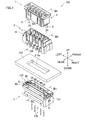
- a connector 100 includes a slider 1 and a female connector (a second connector) 2 to be positioned above a substrate 110, and a guide connector (first connector) 3 to be positioned below the substrate 110.
- a guide connector first connector
- contacts (a first contact) 120 are inserted from below the guide connector 3.
- the slider 1 includes pressing pins (a pressing member) 4 and 5 each extending in up/down directions. The pressing pins 4 and 5 are respectively attached to right and left end portions of the slider 1.
- the substrate 110 has a substantially quadrangular insertion hole 110a, which is a through hole in a direction of the thickness of the substrate 110.
- a substantially quadrangular insertion hole 110a In the insertion hole 110a, an upper end portion of the guide connector 3 is to be positioned (see FIG. 2C ).
- the slider 1 includes a substantially box-shaped housing 6 made of an insulative resin.
- the pressing pins (pressing member) 4 and 5, each extending in the up/down directions, are respectively attached to right and left end portions of the housing 6.
- Each of the pressing pins 4 and 5 extends below the lower end of the housing 6.
- the housing 6 has, in its inside, a space configured to accommodate the female connector 2 (see FIG. 2A ).
- long pins 7a are mounted in the housing 6. Each of the pins 7 extends in the up/down directions, and configured to be inserted into the female connector 2.
- the female connector 2 includes: a female housing (a second housing) 10 having a substantially rectangular parallelepiped shape and made of an insulative resin; and five female contacts (a second contact) 20 mounted in the female housing 10.
- the female housing 10 has five accommodation chambers 11 each capable of accommodating a corresponding female contact 20.
- the five accommodation chambers 11 are aligned in left/right directions.
- the female housing 10 has a bottom wall 12, which is perforated in the up/down directions to form through holes 12a.
- the through holes 12a are formed below the respective accommodation chambers 11, and communicate with the respective accommodation chambers 11.
- Each contact 120 having penetrated the substrate 110 is inserted into the corresponding through hole 12a from below. After passing through the through hole 12a, each contact 120 is inserted into the corresponding accommodation chamber 11.
- Each through hole 12a includes an upper portion having a constant diameter, and a lower portion having a varying diameter.
- the lower portion is tapered so that its diameter increases with an increase in the distance from the upper portion.
- each female contact 20 includes: a polyangular tubular portion 21 whose upper and lower ends are opened; a bent portion 22 bent to extend around the inner periphery of the polyangular tubular portion 21; an elastic portion 23 configured to be elastically displaced, e.g., in the up/down directions; and a fixed portion 24 and a mounting portion 25 which are located outside the accommodation chamber 11 (see FIG. 2B ).
- the fixed portion 24 extends downward from the lower end of the elastic portion 23.
- the fixed portion 24 is fixed to the bottom wall 12 of the female housing 10.
- the mounting portion 25 extends obliquely downward from a midway portion of the fixed portion 24.
- the mounting portion 25 is to be soldered to the substrate 110.
- the polyangular tubular portion 21 includes a front wall portion 31 and back wall portion 32 opposing each other in front/rear directions.
- Each of the front wall portion 31 and the back wall portion 32 has a protruding portion protruding in a direction toward the opposed wall portion.
- the bent portion 22 includes: a lower curved portion 41 extending from the lower end of the front wall portion 31 and curved to form a downward projection; a straight portion 42 extending upward from one end of the lower curved portion 41; and a projecting portion 43 extending from one end of the straight portion 42 while forming a projection toward the front wall portion 31.
- a protruding portion of the front wall portion 31 and the projecting portion 43 is inserted the corresponding pin 7 of the slider 1 (see FIG. 8C ).
- the protruding portion of the back wall portion 32 and the straight portion 42 is inserted the corresponding contact 120 (see FIG. 8B ).
- the guide connector 3 includes a first movable body 50 (rear movable body) and a second movable body 60 (front movable body) opposing each other in the front/rear directions, and a substantially box-shaped housing (a first housing) 70 accommodating these movable bodies.
- the housing 70 includes: a box (a first accommodating member) 80 having an open upper end; and a lid (a second accommodating member) 90 disposed on the box-like body 80 so as to partially close the open upper end.
- the box-like body 80 and the lid 90 are separable from each other in the up/down directions.
- the housing 70 has slits S 1 and S 2 at right and left end portions of the housing 70, respectively.
- Each of the slits S 1 and S 2 is formed across the box-like body 80 and the lid 90.
- strengthening tabs 131 and 132 are respectively inserted (see FIG. 1 ).
- the first movable body 50, the second movable body 60, the housing 70, and the strengthening tabs 131 and 132 are all made of an insulative resin.
- two springs (a biasing member) 141 and 142 are disposed between the first movable body 50 and the second movable body 60.
- One of the springs (biasing member) 141 is disposed between respective right end portions of the two movable bodies 50 and 60, while the other spring (biasing member) 142 is disposed between respective left end portions of the two movable bodies 50 and 60.
- Each of the springs 141 and 142 is elastically deformable in the front/rear directions, and biases the first movable body 50 and the second movable body 60 in directions away from each other.
- the first movable body 50 and the second movable body 60 are thus biased so as to move in the directions away from each other.
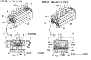
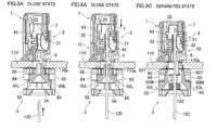
- the movable bodies are configured to make a transition from a close state (see FIGs. 5A , 6A , 9A, and 9B ), in which the movement of the movable bodies in the directions away from each other is restricted by the housing 70, to a separated state (see FIGs. 5B , 6B , and 9C), in which the movable bodies are more distant from each other than in the close state.
- each of the first movable body 50 and the second movable body 60 has a side portion of a stairway-like shape on the opposite side of the body from the surface opposing the counterpart.
- the stairway-like side portion has three stages (an upper stage 50T, a middle stage 50M, and a lower stage 50L of the first movable body 50; and an upper stage 60T, a middle stage 60M, and a lower stage 60L of the second movable body 60).
- the first movable body 50 and the second movable body 60 have substantially the same structure except that of the right and left end portions. In this embodiment, as shown in FIG.
- the section constituted by the right end portions of the two movable bodies 50 and 60 is referred to as a right end section R 1
- the section constituted by the left end portions of the movable bodies 50 and 60 is referred to as a left end section L 1
- the section between the right end section R 1 and the left end section L 1 is referred to as a central section C 1
- the central section C 1 is shaped to have three stages which are the upper stage, the middle stage, and the lower stage.
- Each of the right end section R 1 and the left end section L 1 is shaped to have two stages which are the middle stage and the lower stage (see FIG. 3 ).
- the pressing pins 4 and 5 are supposed to be positioned, respectively.
- the first movable body 50 has, on its surface opposing the second movable body 60, five recesses 50a, 50b, 50c, 50d, and 50e aligned in the left/right directions.
- the second movable body 60 has, on its surface opposing the first movable body 50, five recesses 60a, 60b, 60c, 60d, and 60e aligned in the left/right directions. These recesses are formed so that the recesses of the first movable body 50 respectively oppose the recesses of the second movable body 60 with respect to the front/rear directions.
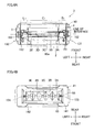
- each recess of the first movable body and a corresponding recess of the second movable body which recesses oppose each other in the front/rear directions (e.g., the recess 50a of the first movable body 50 and the recess 60a of the second movable body 60) form one contact insertion hole (e.g., a contact insertion hole 3A) (see FIG. 1 , 4A, and 4B ).
- the opposing surfaces of the first movable body 50 and the second movable body 60 define five contact insertion holes 3A, 3B, 3C, 3D, and 3E (see FIG. 1 ).
- contacts 120 each extending in the up/down directions are respectively inserted from below (see FIGs. 1 and 2C ). While the contacts 120 are inserted, the first movable body 50 and the second movable body 60 are opposed to each other with the contacts 120 interposed therebetween (see FIG. 6B ).
- the contact insertion hole 3A includes an upper section 3u whose diameter is constant, and a tapered section 3t whose diameter varies to form a tapered shape.
- the tapered section 3t is located below the upper section 3u.
- the tapered section 3t is tapered down toward the upper section 3u.
- the upper section 3u and the upper end of the tapered section 3t have the smallest diameter of the contact insertion hole 3A.
- the smallest diameter is not smaller than the diameter of each contact 120.
- each of the contact insertion holes 3B to 3E has the same structure as that of the contact insertion hole 3A.
- the interface between the first movable body 50 and the second movable body 60 is located substantially at the center with respect to the front/rear directions across its length from the upper end to the lower end (see FIG. 4A ).
- the "front/rear directions" are the directions in which the first movable body 50 and the second movable body 60 are moved relative to each other by the springs 141 and 142.
- the middle stage 50M of the first movable body 50 is provided with a projection 51 projecting toward the second movable body 60, as shown in FIG. 3 .
- the middle stage 60M of the second movable body 60 has a dent 61 capable of receiving the projection 51. Because of this configuration, in the close state, the interface between the middle stage 50M of the first movable body 50 and the middle stage 60M of the second movable body 60 is offset toward the front from the center with respect to the front/rear directions, as shown in FIG. 5A .
- the interface between the lower stage 50L of the first movable body 50 and the lower stage 60L of the second movable body 60 is located substantially at the center with respect to the front/rear directions. Further, the projection 51 of the first movable body 50 overlaps the lower stage 60L of the second movable body 60 when viewed from the up/down directions.
- the lower stages 50L and 60L accommodate the spring 141.
- the spring 141 intersects the interface between the two movable bodies 50 and 60.
- a part of the spring 141 is located in a hole 52 of the first movable body 50, and another part of the spring 141 is located in a hole 62 of the second movable body 60.
- the holes 52 and 62 oppose each other in the front/rear directions, and have substantially the same size. Therefore, in the close state, the rear half of the spring 141 is located in the hole 52, and the front half of the spring 141 is located in the hole 62.
- the spring 141 is held by the first movable body 50 and the second movable body 60 substantially equally.
- the spring 141 extends toward the front and the back equally, as shown in FIG. 5B .
- a recess 151 opening to the right end of the housing 70 is formed in the right end section R 1 .
- the recess 151 extends from the upper ends to the lower ends of the first movable body 50 and the second movable body 60.
- a restriction rib 182 of the housing 70 is positioned in the recess 151.
- the restriction rib 182 is sandwiched by the first movable body 50 and the second movable body 60 in the front/rear directions.
- a surface 54 of the first movable body 50 which surface opposes the restriction rib 182 in the front/rear directions and a surface 64 of the second movable body 60 which surface opposes the restriction rib 182 in the front/rear directions extend in the up/down directions.
- the recesses 55 and 65 are respectively in communication with the holes 52 and 62 in which the spring 141 is disposed.
- the two recesses 55 and 65 are combined, to form a window 153 through which the spring 141 in the holes 52 and 62 is visible. This makes it possible to check the presence/absence of the spring 141 when looking at the bottom of the guide connector 3.
- the recess 55 has a quadrangular shape, while the recess 65 has a semi oval shape.
- the different shapes of the recess 55 and the recess 65 show which is the first movable body 50 or the second movable body 60 between the two bodies.
- the left end section L 1 has substantially the same structure as that of the right end section R 1 . Also in the left end section L 1 , in the close state, the interface between the respective middle stages of the first movable body 50 and the second movable body 60 is offset toward the front from the center with respect to the front/rear directions, while the interface between the respective lower stages of the first movable body 50 and the second movable body 60 is located substantially at the center with respect to the front/rear directions, as shown in FIG. 5A .
- the two movable bodies 50 and 60 partially overlap each other when viewed from the up/down directions.
- the pressing pin 5 is fixed so as to be located above the overlapping portion (see FIG. 4A ). Further, as shown in FIG.
- a recess 152 opening to the left end of the housing 70 is formed in the left end section L 1 .
- the restriction rib 183 is positioned in the recess 152.
- a surface of the first movable body 50 which surface opposes the restriction rib 183 in the front/rear directions and a surface of the second movable body 60 which surface opposes the restriction rib 183 in the front/rear directions extend in the up/down directions.
- a window 154 through which the spring 142 is visible, as shown in FIG. 4B .
- the line of the interface between first movable body 50 and the second movable body 60 which line is on the top surface of the guide connector 3 is located substantially at the center with respect to the front/rear directions in the central section C 1 , while the line of the interface is offset toward the front from the center with respect to the front/rear directions in the right end section R 1 and the left end section L 1 .
- the box-like body 80 of the housing 70 includes: a bottom wall 81; a right wall 82; a left wall 83; and two restriction beams 84 and 85 each extending from the upper end of the right wall 82 to the upper end of the left wall 83. There is a space between the bottom wall 81 and each of the restriction beams 84 and 85.
- the box-like body 80 has an upper end portion having an opening 80a defined by the right wall 82, the left wall 83, and the restriction beams 84 and 85.
- the opening 80a is sized so that the lower stages 50L and 60L of the two movable bodies 50 and 60 in the close state can be disposed at the same time in the opening 80a from above (see
- FIG. 7A is a diagrammatic representation of FIG. 7A .
- the bottom wall 81 has recesses 81p and 81q respectively formed at side portions of the bottom wall 81.
- the recesses 81p and 81q make it easier to pinch the bottom wall 81 with respect to the front/rear directions. This facilitates the movement of the guide connector 3 to the position below the substrate 110.
- the bottom wall 81 has an opening 81a. As shown in FIG. 2C , the size of the opening 81a decreases toward the upper end of the opening 81a.
- the right wall 82 and the left wall 83 respectively have slits 82S and 83S, each extending in the up/down directions.
- the strengthening tabs 131 and 132 are respectively inserted into the slits 82S and 83S.
- a restriction rib 182 protruding toward the left wall 83.
- a restriction rib 183 protruding toward the right wall 82.
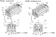
- Each of the restriction ribs 182 and 183 extends in the up/down directions from the upper end to the lower end of corresponding one of the right wall 82 and the left wall 83 (see FIGs. 6A and 6B ).
- the restriction ribs 182 and 183 are always interposed between the first movable body 50 and the second movable body 60, and the restriction ribs 182 and 183 are configured to be slidable on the surfaces 54 and 64 of the two movable bodies 50 and 60.
- the restriction ribs 182 and 183 are in contact with the first movable body 50 and the second movable body 60, and there is hardly any gap between the ribs and the bodies (see FIG. 6A ).
- the restriction beams 84 and 85 of the box-like body 80 shown in FIG. 3 restrict the movement of the two movable bodies 50 and 60 in the directions away from each other (see FIGs. 5A and 5B ).
- the close state as shown in FIG. 5A , the lower stage 50L of the first movable body 50 and the lower stage 60L of the second movable body 60 are respectively in contact with the restriction beams 84 and 85.
- the middle stage 50M of the first movable body 50 and the middle stage 60M of the second movable body 60 are respectively in contact with the restriction beams 84 and 85.
- the restriction beam 84 is provided with, on its top surface (the surface opposing the lid 90), bosses (protrusions) 84a and 84b respectively formed at its right and left end portions.
- the restriction beam 85 is also provided with, on its top surface (the surface opposing the lid 90), bosses (protrusions) 85a and 85b respectively formed at its right and left end portions.
- the bosses 84a, 84b, 85a, and 85b are fitted into four holes formed on an under surface of the lid 90.
- the lid 90 has an opening 90a.
- the opening 90a is smaller than the opening 80a of the box-like body 80.
- the opening 90a is sized so that the upper stages and the middle stages of the first movable body 50 and the second movable body 60 are visible through the opening 90a while the movable bodies are in the close state (see FIG. 4A ).
- tab receiving holes 90b and 90c are respectively formed into which the strengthening tabs 131 and 132 are respectively inserted.
- the tab receiving hole 90b and the slit 82S of the box-like body 80 form the slit S 1 of the housing 70 (see FIG. 1 ).
- the tab receiving hole 90c and the slit 83S of the box-like body 80 form the slit S 2 of the housing 70.
- the lid 90 is provided with bosses 91 and 92 on its top surface.
- the bosses 91 and 92 are configured to be fitted into holes (not shown) formed on a lower surface of the substrate 110 (see FIGs. 5A and 5B ).
- the shapes of the two bosses 91 and 92 are different from each other, and the shapes of the holes into which the bosses 91 and 92 are respectively fitted are also different from each other. Therefore, if the guide connector 3 is positioned the wrong way around (for example, in the opposite way with respect to the left/right directions), the bosses 91 and 92 are not fitted in the holes of the substrate 110. This structure prevents the guide connector 3 from being positioned the wrong way around.
- each of the strengthening tabs 131 and 132 is a substantially quadranuglar plate-like member, and includes a plate portion 131A, 132A extending in the up/down directions, and a horizontal portion 131B, 132B extending from the upper end of the plate portion 131A, 132A in a direction away from the housing 70.
- the plate portions 131A and 132A respectively have, at respective central portions, through holes 131a and 132a each of which has a long hole shape.
- the horizontal portions 131B and 132B are to be soldered to the lower surface of the substrate 110, to enhance the strength of the connection between the guide connector 3 and the substrate 110.
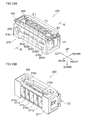
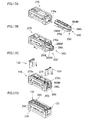
- the first movable body 50 and the second movable body 60 are first brought close to each other while sandwiching the springs 141 and 142 (not shown).
- the two movable bodies 50 and 60 held in the above state are put in the box-like body 80 through the opening 80a at the upper end portion of the box-like body 80.
- an outer side surface of the lower stage 50L of the first movable body 50 and an outer side surface of the lower stage 60L of the second movable body 60 are brought into contact with the restriction beams 84 and 85 of the box-like body 80, respectively, and thereby the two movable bodies 50 and 60 are held in the close state (see FIG. 7B ).
- the lid 90 is attached to the upper end of the box-like body 80 (see FIGs. 7B and 7C ). Thereafter, the strengthening tabs 131 and 132 are respectively inserted into the slits S 1 and S 2 of the housing 70 (see FIGs. 7C and 7D ).
- FIGs. 8A to 8C are sectional views, each taken along a line IIA-IIA, a line IIB-IIB, and a line IIC-IIC of FIG. 1 . It should be noted that, in each of FIGs. 8A to 8C , there are illustrated: the pressing pin 5 out of the pressing pins 4 and 5; the contact insertion hole 3A out of the contact insertion holes 3A to 3E; a contact 120 out of the contacts 120; and the spring 142 out of the springs 141 and 142.
- the female connector 2 is soldered onto an upper surface of the substrate 110.
- the slider 1 is disposed so as to cover the top of the female connector 2, and each of the pins 7 is not inserted between the protruding portion of the front wall portion 31 and the projecting portion 43 of the corresponding female contact 20 (semi-fit state).
- the guide connector 3 is secured to the lower surface of the substrate 110, and the first movable body 50 and the second movable body 60 are in the close state.
- the outer side surface of the lower stage 50L of the first movable body 50 and the outer side surface of the lower stage 60L of the second movable body 60 are respectively in contact with the restriction beams 84 and 85 of the guide connector 3.
- the female connector 2 is on the substrate 110.
- Each of the pressing pins 4 and 5 is located above the middle stage 50M of the first movable body 50 and the middle stage 60M of the second movable body 60, at a position offset toward the front from the center of the guide connector 3 with respect to the front/rear directions (see FIG. 5A ).
- each contact 120 is inserted into the guide connector 3 from below (see FIG. 8B ).
- Each contact 120 passes through the corresponding contact insertion hole (3A to 3E) of the guide connector 3, and penetrates the substrate 110.
- each contact 120 is inserted between the protruding portion of the back wall portion 32 and the straight portion 42 of the corresponding female contact 20. This causes the contact 120 to contact at least one of the back wall portion 32 and the straight portion 42, and thereby electric connection between them is established.
- the slider 1 is pressed down (full-fit state). This moves the pressing pins 4 and 5 downward, to press the middle stage 50M of the first movable body 50 and the middle stage 60M of the second movable body 60 (see FIG. 5A ). With this, the two movable bodies 50 and 60 are pressed down, and moved away from the female connector 2. The lower stage 50L of the first movable body 50 and the lower stage 60L of the second movable body 60 are also moved downward, with the result that the outer side surfaces of the lower stages 50L and 60L detach from the restriction beams 84 and 85 (see FIG. 5B ). Thus, the first movable body 50 and the second movable body 60 are released.
- the springs 141 and 142 extend, which moves the first movable body 50 and the second movable body 60 in directions away from each other, to move the first and second movable bodies 50 and 60 away from the contacts 120 (see FIG. 8C ).
- the middle stage 50M of the first movable body 50 and the middle stage 60M of the second movable body 60 are respectively brought into contact with the restriction beams 84 and 85, and the upper stage 50T of the first movable body 50 and the upper stage 60T of the second movable body 60 are brought into contact with the lid 90 (see FIG. 8C ). This restricts further movement of the first movable body 50 and the second movable body 60.
- FIGs. 5B , 6B , and 8C each shows the state where the pressing pins 4 and 5 are pressed down while the opposing surfaces of the first movable body 50 and the second movable body 60 lie along the up/down directions (i.e., the direction orthogonal to the substrate).
- the first movable body 50 and the second movable body 60 are unstable because only the lower stages 50L and 60L are held by the restriction beams 84 and 85 (see FIG. 5A ), and therefore, rotational movement of the first movable body 50 and/or the second movable body 60 may be caused, if vibrations or the like are created before the pressing pins 4 and 5 are pressed down, for example, during the movement of the guide connector 3 to the position below the substrate 110.
- the restriction ribs 182 and 183 are always interposed between the first movable body 50 and the second movable body 60 (see FIG. 6A ), and this restricts the rotational movement of the first movable body 50 and the second movable body 60.
- the first movable body 50 rotationally moves while sliding on and contacting the restriction rib 182, and therefore the degree of rotation of the first movable body 50 is limited.
- the second movable body 60 also rotationally moves while sliding on and contacting the restriction rib 182, and therefore the degree of rotation of the second movable body 60 is limited.
- the degree of rotation of the first movable body 50 and the degree of rotation of the second movable body 60 are smaller than those in the case where the restriction ribs 182 and 183 are not provided. Due to this structure, the first movable body 50 and the second movable body 60 are sufficiently pressed down by the pressing pins 4 and 5. This enables the first movable body 50 and the second movable body 60 to make a transition to the separated state, so that the two movable bodies 50 and 60 are moved away from the contacts 120, as shown in FIG. 8C .
- the connector 100 of this embodiment provides the following advantageous effects.
- the first movable body 50 and the second movable body 60 are pressed using the pressing pins 4 and 5 after the electrical connection between the contacts 120 and the respective female contacts 20 are established, and thereby the two movable bodies 50 and 60 are moved away from the contacts 120.
- the contacts 120 are not influenced by such vibration and/or resonance. Accordingly, wear of and damage to the contacts 120 are prevented.
- restriction ribs 182 and 183 are disposed between the first movable body 50 and the second movable body 60, and the restriction ribs 182 and 183 are always interposed between the two movable bodies 50 and 60 during the transition from the close state to the separated state.
- the first movable body 50 and the second movable body 60 rotationally move while contacting the restriction ribs 182 and 183, and therefore the degrees of the rotation of the bodies are smaller.
- restriction ribs 182 and 183 extend in the up/down directions (the direction orthogonal to the substrate 110), and the surfaces 54 and 64 which oppose the restriction ribs 182 and 183 also extend in the up/down directions. This ensures restriction of the rotational movement of the first movable body 50 and the second movable body 60.
- first movable body 50 and the second movable body 60 are configured to be slidable on the restriction ribs 182 and 183, and in the close state, there is no gap between the first movable body 50 and each of the restriction ribs 182 and 183 and between the second movable body 60 and each of the restriction ribs 182 and 183. That is, in the close state, the first movable body 50 and the second movable body 60 are in contact with each of the restriction ribs 182 and 183, and this ensures restriction of the rotational movement of the first movable body 50 and the second movable body 60.
- the positions where the pressing pins 4 and 5 are fixed are offset toward the front from the center with respect to the front/rear directions.
- the line of the interface between the first movable body 50 and the second movable body 60 is offset toward the front from the center with respect to the front/rear directions. Therefore, it is possible to press the two movable bodies 50 and 60 using the pressing pins 4 and 5. As a result, the two movable bodies 50 and 60 are moved away from the contacts 120.
- the interface between the lower stages 50L and 60L accommodating the springs 141 and 142 is positioned at the center with respect to the front/rear directions, and therefore each of the springs 141 and 142 is equally held by the two movable bodies 50 and 60. This allows the springs 141 and 142 to extend in balance in the front/rear directions, to move the both movable bodies 50 and 60 away from the contacts 120.
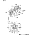
- FIGs. 10A to 19C The following describes a second embodiment of the present invention with reference to FIGs. 10A to 19C .
- a connector of the second embodiment is different from that of the first embodiment in the structure of the guide connector. Note that the components same as those in the first embodiment are given the same reference numerals, and the description thereof will be omitted if appropriate. Further, in FIGs. 14B and 15B , the pressing pins 4 and 5 are not illustrated.
- a guide connector 203 includes: a first movable body 250 (a rear movable body) and a second movable body 260 (a front movable body); and a substantially box-shaped housing (a first housing) 270 accommodating the first and second movable bodies 250 and 260.
- the strengthening tabs 131 and 132 are respectively attached to the right and left end portions of the housing 270.
- the first movable body 250, the second movable body 260, the housing 270, and the strengthening tabs 131 and 132 all are made of an insulative resin. As shown in FIG.
- the springs (biasing member) 141 and 142 are respectively disposed between the right end portions of the two movable bodies 250 and 260 and between the left end portions of the two movable bodies 250 and 260.
- the opposing surfaces of the first movable body 250 and the second movable body 260 are in contact with each other.
- the pressing pins 4 and 5 respectively to be positioned above a right end section R 2 and a left end section L 2 of the first movable body 250 and the second movable body 260 (see FIG. 13A ).
- a central section C 2 of the first movable body 250 and the second movable body 260 has three stages which are an upper stage, a middle stage, and a lower stage.
- the first movable body 250 has, on a surface opposing the second movable body 260, five recesses 250a, 250b, 250c, 250d, and 250e aligned in the left/right directions.
- the second movable body 260 has, on a surface opposing the first movable body 250, five recesses 260a, 260b, 260c, 260d, and 260e aligned in the left/right directions.
- recesses are formed so that the recesses of the first movable body 250 respectively oppose the recesses of the second movable body 260 with respect to the front/rear directions (for example, the recess 250a of the first movable body 250 opposes the recess 260a of the second movable body 260).
- opposing two recesses e.g., the recess 250a and the recess 260a
- one contact insertion hole e.g., a contact insertion hole 203A
- the opposing surfaces of the first movable body 250 and the second movable body 260 define five contact insertion holes 203A, 203B, 203C, 203D, and 203E.
- Each of the contact insertion holes 203A, 203B, 203C, 203D, and 203E includes an upper section 203u whose diameter is constant, and a tapered section 203t whose diameter decreases toward the upper section 203u (see FIG. 19A ).
- the tapered section 203t is located below the upper section 203u.
- FIG. 19A illustrates the contact insertion hole 203A out of the contact insertion holes 203A to 203E.
- the upper section 203u and the upper end of the tapered section 203t have the smallest diameter of the contact insertion hole (203A to 203E). The smallest diameter is not smaller than the diameter of each contact 120.
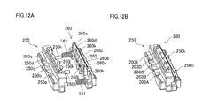
- the first movable body 250 is provided with cylindrical bosses (a projection) 250h, 250i, 250j, and 250k aligned in the left/right directions.
- Each of the bosses protrudes toward the second movable body 260 and is formed between corresponding two adjacent recesses.
- the right and left bosses 250h and 250k are longer than the two bosses 250i and 250j interposed between the bosses 250h and 250k.
- the second movable body 260 has cylindrical holes (a space) 260h, 260i, 260j, and 260k which are through holes each extending in the front/rear directions. Each of the holes 260h, 260i, 260j, and 260k is formed between the corresponding two recesses adjacent to each other (e.g., between the recess 260a and the recess 260b). The holes 260h, 260i, 260j, and 260k are positioned so as to correspond to the bosses 250h, 250i, 250j, and 250k of the first movable body 250.
- the bosses 250h, 250i, 250j, and 250k of the first movable body 250 are respectively inserted into the holes 260h, 260i, 260j, and 260k of the second movable body 260.
- the close state as shown in FIG. 12B , the right and left bosses 250h and 250k penetrate the second movable body 260, and protrude from the second movable body 260 (see FIG. 13A ).
- the boss 250h for example, is sandwiched, with respect to the up/down directions, by an upper wall portion (a first support surface) 261u and a lower wall portion (a second support surface) 2611 each of which wall portions is a part of a curved surface defining the hole 260h.
- the thus sandwiched portion of the boss 250h overlaps the second movable body 260 when viewed from the up/down directions.
- first movable body 250 attempts to rotate, its rotation is stopped by the lower wall portion 2611 contacting the boss 250h. Further, if the second movable body 260 attempts to rotate, its rotation is stopped by the upper wall portion 261u contacting the boss 250h.
- the bosses 250h, 250i, 250j, and 250k guide the first movable body 250 and the second movable body in the front/rear directions, as shown in FIGs. 13A to 14B .
- the interface between the first movable body 250 and the second movable body 260 is located substantially at the center with respect to the front/rear directions, across the length of the interface from the upper end to the lower end, except the interface, for example, between the boss 250h and the hole 260h. That is, except the interface between each boss (250h, 250i, 250j, 250k) and the corresponding hole (260h, 260i, 260j, and 260k), the interface is located substantially at the center with respect to the front/rear directions across its length from the upper end to the lower end.
- a middle stage 250M of the first movable body 250 is provided with a projection 251 projecting toward the second movable body 260.
- a middle stage 260M of the second movable body 260 has a dent 261 capable of receiving the projection 251. In the close state, the projection 251 is received in the dent 261. Therefore, as shown in FIG. 11 , in the right end section R 2 , a middle stage 250M of the first movable body 250 is provided with a projection 251 projecting toward the second movable body 260.
- a middle stage 260M of the second movable body 260 has a dent 261 capable of receiving the projection 251. In the close state, the projection 251 is received in the dent 261. Therefore, as shown in FIG.
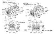
- the interface between the middle stage 250M of the first movable body 250 and the middle stages 260M of the second movable body 260 is offset toward the front from the center with respect to the front/rear directions, while the interface between a lower stage 250L of the first movable body 250 and a lower stage 260L of the second movable body 260 is located substantially at the center with respect to the front/rear directions.
- the projection 251 of the first movable body 250 overlaps the lower stage 260L of the second movable body 260 when viewed from the up/down directions.
- the pressing pin 4 is to be positioned above the overlapping portions.
- the lower stages 250L and 260L accommodate the spring 141.
- the interface between the two movable bodies 250 and 260 intersects the spring 141.
- the spring 141 is located in a hole 252 of the first movable body 250 and a hole 262 of the second movable body 260.
- the holes 252 and 262 oppose each other in the front/rear directions, and have substantially the same size. Therefore, in the close state, the rear half of the spring 141 is located in the hole 252, and the front half of the spring 141 is located in the hole 262.
- the spring 141 is held by the first movable body 250 and the second movable body 260 substantially equally.
- the spring 141 extends toward the front and the back equally, as shown in FIG. 15B .
- the left end section L 2 has substantially the same structure as that of the right end section R 2 .
- the interface between the respective middle stages of the first movable body 250 and the second movable body 260 in the close state is offset toward the front from the center with respect to the front/rear directions, while the interface between the respective lower stages of the first movable body 250 and the second movable body 260 is positioned substantially at the center with respect to the front/rear directions.
- the two movable bodies 250 and 260 partially overlap each other when viewed from the up/down directions.
- the pressing pin 5 is fixed so as to be located above the overlapping portions (see FIG. 14A ).
- the line of the interface between the first movable body 250 and the second movable body 260 which line is on a top surface of the guide connector 203 is located substantially at the center with respect to the front/rear directions in the central section C 2 , while the line of the interface is offset toward the front from the center with respect to the front/rear directions in the right end section R 2 and in the left end section L 2 .
- the housing 270 includes a bottom wall 271, a right wall 272, a left wall 273, and a top wall 274. These walls define, inside the housing 270, an accommodation space S capable of accommodating the first movable body 250 and the second movable body 260.
- the housing 270 has, at the right and left end portions thereof, holes 270a and 270b each communicating with the accommodation space S. Each of the holes 270a and 270b is sized so that the two movable bodies 250 and 260 held in the close state can be inserted at the same time in the left/right directions (see FIG. 17B ).
- the bottom wall 271 has five guide holes 271a, 271b, 271c, 271d, and 271e aligned in the left/right directions. Each of the holes is a through hole extending in a direction of the thickness of the bottom wall 271 (i.e., in the up/down directions). Above the guide holes 271a, 271b, 271c, 271d, and 271e, the contact insertion holes 203A, 203B, 203C, 203D, and 203E are respectively positioned (see FIGs. 19A to 19C ).
- the right wall 272 and the left wall 273 of the housing 270 respectively have slits 272s and 273s into which the strengthening tabs 131 and 132 are respectively inserted.
- the top wall 274 has an opening 274a.
- the top wall 274 has four recesses 275a, 275b, 275c, and 275d aligned in the left/right directions. These recesses are formed on a front inner wall surface of inner wall surfaces of the top wall 274 which surfaces defining the opening 274a in the front/rear directions.
- the bosses 250h and 250k are respectively fitted into the two recesses 275b and 275c of the four recesses (see FIG. 13A ), which two recesses are interposed between the remaining right and left recesses.
- two recesses 275e and 275f are formed so as to be aligned in the left/right directions, as shown in FIG. 11 .
- the top wall 274 is provided with bosses 274b and 274c on a top surface of the top wall 274.
- the bosses 274b and 274c are configured to be fitted in holes (not shown) on the lower surface of the substrate 110 (see FIGs. 14A to 15B ).
- the middle stage 250M of the first movable body 250 and the middle stage 260M of the second movable body 260 contact an inner circumferential surface (the surface facing the opening 274a) of the top wall 274 except the portions where the recesses 275a, 275b, 275c, 275d, 275e, and 275f are formed.
- each of the lower stages 250L and 260L contacts portions projecting downward from an under surface of the top wall 274 (projections 276a and 276b in FIGs. 15A and 16 , projections 276c and 276d in FIG. 10B ).
- the projections 276a, 276b, 276c, and 276d respectively define the recesses 275a, 275d, 275e, and 275f formed on the inner circumferential surface of the top wall 274 (see FIG. 11 ).
- each of the middle stage 250M of the first movable body 250 and the middle stage 260M of the second movable body 260 contacts the portions projecting downward from the under surface of the top wall 274 (the projections 276a and 276b shown in FIG. 15B , the projections 276c and 276d shown in FIG. 10B ). This restricts the movement of the first movable body 250 and the second movable body 260 in the directions away from each other.
- the first movable body 250 and the second movable body 260 are first brought close to each other while sandwiching the springs 141 and 142 (not shown).
- the two movable bodies 250 and 260 held in the above state are put in the housing 270 through the hole 270a at the right end portion of the housing 270 (see FIG. 17B ).
- the first movable body 250 and the second movable body 260 are lifted up while maintaining the close state.
- the middle stage 250M and the lower stage 250L of the first movable body 250 and the middle stage 260M and the lower stage 260L of the second movable body 260 are brought into contact with the inner circumferential surface of the top wall 274 of the housing 270 (see FIG. 16 ). This keeps the two movable bodies 250 and 260 in the close state.
- the strengthening tabs 131 and 132 are respectively inserted into the slits 272s and 273s of the housing 270 ( FIGs. 17C and 17D ).
- the spring 141 is visible through the through hole 131a of the strengthening tab 131 as shown in FIG. 18B .
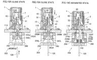
- FIGs. 19A to 19C are sectional views, each taken along the line IIA-IIA and the line IIB-IIB of FIG. 1 , and a line X-X of FIG. 10 . It should be noted that in each of FIGs. 19A to 19C , there are illustrated: the pressing pin 5 out of the pressing pins 4 and 5; the contact insertion hole 203A out of the contact insertion holes 203A to 203E; a contact 120 out of the contacts 120; and the spring 142 out of the springs 141 and 142.
- the female connector 2 is soldered onto the upper surface of the substrate 110.
- the slider 1 is disposed so as to cover the top of the female connector 2, and each of the pins 7 is not inserted between the protruding portion of the front wall portion 31 and the projecting portion 43 of the corresponding female contact 20 (semi-fit state).
- the guide connector 203 is secured to the lower surface of the substrate 110, and the first movable body 250 and the second movable body 260 are in the close state.
- Each of the pressing pins 4 and 5 is located above the middle stage 250M of the first movable body 250 and the middle stage 260M of the second movable body 260, and at a position offset toward the front from the center of the guide connector 203 with respect to the front/rear directions (see FIG. 16 ).
- each contact 120 is inserted into the guide connector 203 from below (see FIG. 19B ).
- Each contact 120 passes through the corresponding contact insertion hole (203A to 203E) of the guide connector 203, and penetrates the substrate 110.
- each contact 120 is inserted between the protruding portion of the back wall portion 32 and the straight portion 42 of the corresponding female contact 20. This causes the contact 120 to contact at least one of the back wall portion 32 and the straight portion 42, and thereby electric connection between them is established.
- the slider 1 is pressed down (full-fit state). This moves the pressing pins 4 and 5 downward, to press the middle stage 250M of the first movable body 250 and the middle stage 260M of the second movable body 260. With this, the two movable bodies 250 and 260 are pressed down, and moved away from the female connector 2. Further, the middle stage 250M and the lower stage 250L of the first movable body 250 and the middle stage 260M and the lower stage 260L of the second movable body 260 detach from the inner circumferential surface of the top wall 274. Thus, the first movable body 250 and the second movable body 260 are released, and thereby the springs 141 and 142 extend.
- the first movable body 250 and the second movable body 260 are moved in the directions away from each other, and moved away from the contacts 120 (see FIG. 19C ). Thereafter, the middle stage 250M of the first movable body 250 and the middle stage 260M of the second movable body 260 are brought into contact with the inner circumferential surface of the top wall 274 (specifically, with the projections 276c and 276d shown in FIG. 10B , the projections 276a and 276b shown in FIG. 15B ). This restricts further movement of the first movable body 250 and the second movable body 260.
- each pin 7 is pressed down. This causes each pin 7 to be positioned between the protruding portion of the front wall portion 31 and the projecting portion 43 of the corresponding female contact 20, as shown in FIG. 19C . This displaces the projecting portion 43 toward the corresponding contact 120, thus improving accessibility between the female contact 20 and the contact 120.
- the first movable body 250 and the second movable body 260 are pressed using the pressing pins 4 and 5 after the electric connection between the contacts 120 and the respective female contacts 20 is established, and thereby the two movable bodies 250 and 260 are moved away from the contacts 120.
- the contacts 120 are not influenced by such vibration and/or resonance. Accordingly, wear of and damage to the contacts 120 are prevented.
- the positions where the pressing pins 4 and 5 are fixed are offset toward the front from the center with respect to the front/rear directions.
- the line of the interface between the first movable body 250 and the second movable body 260, which line is on the top surfaces is offset toward the front from the center with respect to the front/rear directions. Therefore, the two movable bodies 250 and 260 are pressed by the pressing pins 4 and 5. As a result, the two movable bodies 250 and 260 are moved away from the contacts 120.
- each of the right end section R 2 and the left end section L 2 the interface between the lower stages 250L and 260L accommodating the springs 141 and 142 is positioned substantially at the center with respect to the front/rear directions, and therefore each of the springs 141 and 142 is equally held by the two movable bodies 250 and 260. This allows the springs 141 and 142 to extend in balance in the front/rear directions, to move the both movable bodies 250 and 260 away from the contacts 120.
- each of the bosses 250h, 250i, 250j, and 250k of the first movable body 250 is supported by the upper wall portion and the lower wall portion defining the corresponding one of the holes 260h, 260i, 260j, and 260k of the second movable body 260 (e.g., the boss 250h is supported by the upper wall portion 261u and the lower wall portion 2611) (see FIG. 14A ), and this restricts the rotational movement of the first movable body 250 and the second movable body 260. This prevents the first movable body 250 and/or the second movable body 260 from being positionally shifted before being pressed by the pressing pins 4 and 5. This ensures pressing of the two movable bodies 250 and 260.
- the bosses 250h, 250i, 250j, and 250k are not located in the holes 260h, 260i, 260j, and 260k, respectively, and therefore the two movable bodies 250 and 260 are not in contact with each other (see FIG. 13B ). This prevents transmission of vibration from one of the movable bodies to the other movable body.
- the rotational movement of the two movable bodies 250 and 260 is restricted with a simple structure in which the upper wall portion and the lower wall portion defining each hole (260h, 260i, 260j, 260k) are configured to support the corresponding boss (e.g., the upper wall portion 261u and the lower wall portion 2611 defining the hole 260h are configured to support the boss 250h).
- each of the bosses 250h and 250k has a longer length in the front/rear directions, which allows the first movable body 250 and the second movable body 260 to be guided until immediately before completion of a transition to the separated state.
- the two movable bodies 250 and 260 are moved away from each other in their right directions (the front/rear directions).
- the structure of the slider 1, the structure of the female connector 2, and the structure of the pressing pins 4 and 5 are respectively not limited to those described in the above-described embodiments, and may be altered.
- the pressing pins 4 and 5 do not have to be attached to the slider 1.
- the pressing member may be a member constituted by a long rod, and may be attached to a member other than the slider. Further, the slider 1 does not have to be included.
- the transition of the first movable body 50, 250 and the second movable body 60, 260 from the close state to the separated state is made (see FIGs. 8C and 19C ) after the electrical connection between each contact 120 and the corresponding female contact 20 is established.
- the timing of the transition to the separated state is not limited to this.
- the transition to the separated state may be made simultaneously with the establishment of the electrical connection between each contact 120 and the corresponding female contact 20, as long as each contact 120 has been inserted into the corresponding contact insertion hole (e.g., the contact insertion hole 3A, 203A) of the guide connector 3, 203.
- the transition to the separated state may be made after the insertion of each contact 120 into the corresponding contact insertion hole and before the contact 120 is electrically connected with the corresponding female contact 20.
- each of the above-described embodiments deals with the case where the pressing pins (pressing member) 4 and 5 press both of the first movable body 50, 250 and the second movable body 60, 260; however, the pressing member may press one of these movable bodies.
- the structure shown in FIG. 20A is possible, in which each of the pressing pins 4 and 5 is positioned substantially at the center of the guide connector 3 with respect to the front/rear directions, to press the first movable body 50 without pressing the second movable body 60. (Note that in FIG.
- each of the pressing pins 4 and 5 is positioned above the portion of the first movable body 50 which portion overlaps the second movable body 60.
- the second movable body 60 is indirectly pressed, and therefore the two movable bodies 50 and 60 make transition to the separated state.
- the first movable body 50, 250 and the second movable body 60, 260 partially overlap each other in the right end section R 1 , R 2 and in the left end section L 1 , L 2 .
- the two movable bodies do not have to overlap each other.
- the two movable bodies may partially overlap each other in either one of the right end section and the left end section.
- the interface between the middle stages 50M and 60M is offset toward the front from the center with respect to the front/rear directions in each of the right end section R 1 and the left end section L 1 (see FIG. 5A ).
- the interface between the middle stages 250M and 260M is offset toward the front from the center with respect to the front/rear directions in each of the right end section R 2 and the left end section L 2 (see FIG. 15A ).
- the interface between the lower stages 50L, 250L and 60L, 260L may be offset.
- the interface between a middle stage 550M of a first movable body 550 and a middle stage 560M of a second movable body 560 in the close state is positioned around the center with respect to the front/rear directions, and the interface between a lower stage 550L of the first movable body 550 and a lower stage 560L of the second movable body 560 is offset toward the front from the center with respect to the front/rear directions.
- the pressing pins fixed so as to be located at or around the center of the guide connector 3 with respect to the front/rear directions the first movable body 550 and the second movable body 560 are pressed.
- the pressing pins may be fixed so as to be located offset toward the front from the center of the guide connector 3 with respect to the front/rear directions, as are in the above-described embodiments.
- the first movable body 550 is directly pressed.
- the portion of the first movable body 550 which overlaps the second movable body 560 is pressed, and therefore the second movable body 560 is indirectly pressed.
- the two movable bodies 550 and 560 make a transition to the separated state.
- the strengthening tabs 131 and 132 are respectively inserted into the right and left end portions of the housing 70, 170; however, the strengthening tabs 131 and 132 do not have to be inserted.
- the first movable body 50, 250 and the second movable body 60, 260 of the guide connector 3, 203 have similar structure; however, their structures may be different from each other.
- the springs 141 and 142 are used as the biasing member in each of the above-described embodiments; however, the biasing member may be a member other than the springs.
- an elastic member such as rubber may be used as the biasing member.
- restriction ribs 182 and 183 of the first embodiment may be altered as follows.
- the first embodiment deals with the case where each of the restriction ribs 182 and 183 is disposed between the first movable body 50 and the second movable body 60; however, the restriction ribs 182 and 183 do not have to be included.
- the first embodiment deals with the case where the restriction ribs 182 and 183 are provided to the housing 70; however, the restriction ribs 182 and 183 may be members separate from the housing 70.
- the shape, size, position and the like of the restriction ribs 182 and 183 are not limited those described in the first embodiment, and may be altered.
- the restriction rib 182 extends in the up/down directions from the upper end to the lower end of the right wall 82; however, the restriction rib 182 does not have to extend in such a manner, and may be provided merely at the upper end portion of the right wall.
- each of the surfaces 54 and 64 of the first movable body 50 and the second movable body 60 which surface opposes the restriction rib 182, 183 extends in the up/down directions.
- each of the surfaces 54 and 64 may be curved so as to form a protrusion toward the restriction rib 182, 183.
- the windows 153 and 154 through which the springs 141 and 142 are respectively visible are formed at the bottom of the body formed by the first movable body 50 and the second movable body 60.
- a window may be formed through the right wall portion and/or the left wall portion of the housing of the guide connector, for example.
- the bosses 250h, 250i, 250j, and 250k, and the holes 260h, 260i, 260j, and 260k of the second embodiment may be altered as follows.
- the bosses 250h, 250i, 250j, and 250k, and the holes 260h, 260i, 260j, and 260k are provided in the central section C 2 of the first movable body 50 and the second movable body 60; however, these bosses and holes may be provided in the right end section R 2 and/or in the left end section L 2 .
- the bosses 250h, 250i, 250j, and 250k of the first movable body 250 are respectively configured to be inserted into the holes 260h, 260i, 260j, and 260k of the second movable body 260, and each boss is supported in such a manner that, for example, as shown in FIG. 14A , the boss 250h is supported by the upper wall portion (first support surface) 261u and the lower wall portion (second support surface) 2611 which wall portions form the inner wall defining the hole 260h.
- each of the bosses may be supported in another manner.
- the second movable body may be provided with two projections A and B, each of which projections projects toward the first movable body and opposes to the counterpart projection in the up/down directions, so that the bosses of the first movable body can be positioned in a space formed between the two projections A and B. Since each boss is supported by the projections A and B in the up/down directions, the rotation of the first movable body and the second movable body is prevented.
- support surfaces opposing each other in the left/right directions do not have to be provided.
- the bosses 250h, 250i, 250j, and 250k of the first movable body 250 are not in contact with the second movable body 260 in the separated state (see FIG. 13B ); however, the bosses may be in contact with the second movable body.
- the first movable body 250 is provided with the bosses 250h, 250i, 250j, and 250k and the second movable body 260 has the holes 260h, 260i, 260j, and 260k; however, the following arrangement is also possible: the first movable body has the holes, and the second movable body is provided with the bosses.
- the second movable body 260 has holes 260h, 260i, 260j, and 260k functioning as spaces for receiving the bosses 250h, 250i, 250j, and 250k.
- holes may be provided depending on the length of the bosses.
- each boss and each hole is not limited to that described in the second embodiment, and may be altered.
- the contacts 120 After passing through respective contact insertion holes 3A to 3E of a guide connector 3 and penetrating the substrate 110, the contacts 120 are inserted into a female housing 10. After the electrical connection between the contacts 120 and female contacts 20 are respectively established, a slider 1 is pressed down, which causes pressing pins 4 and 5 to press a first movable body 50 and a second movable body 60. With this, a lower stage 50L of the first movable body 50 and a lower stage 60L of the second movable body 60 detach from restriction beams 84 and 85. This allows springs 141 and 142 to extend, to move the first movable body 50 and the second movable body 60 away from the contacts 120.
Landscapes
- Engineering & Computer Science (AREA)
- Manufacturing & Machinery (AREA)
- Details Of Connecting Devices For Male And Female Coupling (AREA)
- Coupling Device And Connection With Printed Circuit (AREA)
- Connector Housings Or Holding Contact Members (AREA)
Abstract
Description
- The present invention relates to a connector including a housing configured to guide a contact into a contact insertion hole formed through a substrate.
- As a connector mounted in an automobile or the like, there has been known a connector configured to be placed on a substrate, into which connector a counterpart contact is inserted from below through the substrate. The counterpart contact is inserted into the connector after passing through a contact insertion hole formed through the substrate. If there is misalignment between the counterpart contact and the contact insertion hole due to the tolerance or the like at the time of manufacturing, the counterpart contact cannot be smoothly inserted into the contact insertion hole. Such a problem becomes a more significant concern, with an increase in the number of counterpart contacts.
- To address this problem, Japanese Unexamined Patent Publication No.
146873/2010 Tokukai 2010-146873 - In the above guide housing, the diameter of the upper end of the guide hole is substantially the same as the diameter of the counterpart contact. This facilitates guiding of the counterpart contact inserted in the guide hole to the contact insertion hole. While the counterpart contact is in the guide hole, the counterpart contact is close to an inner circumferential surface of the guide housing, which surface defines the guide hole.
- Areas at or nearby a power supply and a source of power (such as an engine) for an automobile, where a connector is mounted, are likely to be subjected to vibration. This vibration may vibrate the guide housing, which causes the inner circumferential surface of the guide housing to contact the counterpart contact, leading to wear of the counterpart contact. Further, if the substrate is vibrated in addition to the guide housing to cause resonance, the stress to the counterpart contact is increased. As a result, the counterpart contact may be damaged.
- In view of the above problem, an object of the present invention is to provide a connector capable of preventing wear of and damage to a counterpart contact.
- According to one aspect of the present invention, a connector includes: a first connector and a second connector which are configured to be disposed across a substrate from each other; and a pressing member.
- The first connector includes a first housing accommodating first and second movable bodies configured to be located across a first contact from each other, the first contact extending in a direction orthogonal to the substrate, and a biasing member configured to bias the first and second movable bodies in directions away from each other.
- The first and second movable bodies accommodated in the first housing are configured to make a transition from a close state to a separated state, the close state being a state in which the first and second movable bodies are biased by the biasing member and movement of the first and second movable bodies in the directions away from each other is restricted by the first housing, the separated state being a state in which the first and second movable bodies are more distant from the second connector than in the close state and the first and second movable bodies are made more distant from each other than in the close state by the biasing member.
- The first and second movable bodies define a contact insertion hole in the close state, the contact insertion hole having a smallest diameter not smaller than a diameter of the first contact and including a section whose diameter decreases toward the substrate.
- The second connector includes a second housing and a second contact mounted in the second housing, the second contact configured to be electrically connected to the first contact passing through the contact insertion hole and penetrating the substrate.
- The pressing member is configured to press at least one of the first and second movable bodies after the first contact passes through the contact insertion hole and penetrates the substrate and the electric connection between the first contact and the second contact is established, thereby to cause the first and second movable bodies to make the transition from the close state to the separated state.
- In the first aspect of the present invention, at least one of the first and second movable bodies is pressed after the electric connection between the first contact and the second contact is established, and thereby the two movable bodies are moved away from the first contact. Therefore, even if the first housing is vibrated, or even if the first housing and the substrate are vibrated to cause resonance, wear of and damage to the first contact are prevented.
- In the first aspect of the present invention, it is preferable that the first connector further includes a restriction rib disposed between the first and second movable bodies; and the restriction rib is always interposed between the first and second movable bodies during the transition from the close state to the separated state.
- In the above structure, rotational movement of the first and second movable bodies is made while the first and second movable bodies are in contact with the restriction rib, and therefore the degrees of the rotation are smaller. Thus, even if the movable bodies rotationally move before being pressed, the two movable bodies are not positionally shifted significantly, and this ensures the transition of the movable bodies to the separated state.
- Further, in the above structure, it is preferable that the restriction rib extends in the direction orthogonal to the substrate. This structure ensures restriction of the rotational movement of the first movable body and/or the second movable body before the press.
- Additionally, in the above structure, it is preferable that each of surfaces of the first and second movable bodies which surfaces oppose the restriction rib extends in the direction orthogonal to the substrate. Since each of the surfaces of the first and second movable bodies which surfaces oppose the restriction rib extends in the direction orthogonal to the substrate, the rotational movement of the first movable body and/or the second movable body is reliably restricted.
- Further, in the above structure, it is preferable that the first and second movable bodies are configured to be slidable on the restriction rib, and no gap is formed between the first and second movable bodies and the restriction rib. The first and second movable bodies are in contact with the restriction rib, and this ensures restriction of the rotational movement of the first movable body and/or the second movable body.
- Further, it is preferable that the restriction rib is provided to the first housing. This ensures the transition of the two movable bodies to the separated state with a simple structure.
- Alternatively, in the connector according to the first aspect of the present invention, it is preferable that the first movable body includes a first support surface and a second support surface opposing the first support surface in the direction orthogonal to the substrate, the first support surface and the second support surface create a space therebetween; and that the second movable body includes a projection projecting toward the first movable body and configured to be positioned in the space in the close state.
- In this structure, the projection of the second movable body is supported by the first support surface and the second support surface of the first movable body, thereby restricting the rotational movement of the first movable body and/or the second movable body. This prevents the movable bodies from being positionally shifted before being pressed, thereby ensuring the transition of the two movable bodies to the separated state.
- In the above structure, it is preferable that the projection is not positioned in the space in the separated state. The two movable bodies are not in contact with each other in the separated state, and this prevents transmission of vibration from one of the movable bodies to the other movable body.
- Further, in the above structure, it is preferable that each of the first and second support surfaces is a part of a curved surface defining a hole formed in the first movable body. With a simple structure in which the projection of the second movable body is positioned in the hole of the first movable body, the rotational movement of the first movable body and/or the second movable body is restricted.
- Further, it is preferable that at least a part of a line of an interface between the first and second movable bodies is offset from a center with respect to a relative movement direction in which the first and second movable bodies are moved relative to each other, the line being a line of intersection of (i) surfaces of the first and second movable bodies each of which surfaces opposes the pressing member and (ii) the interface between the first and second movable bodies. With this, the two movable bodies are pressed even in the case where the location of the pressing member is offset from the center, and therefore the movable bodies make a transition to the separated state.
- Further, in the above structure, it is preferable that, the first movable body and the second movable body partially overlap each other when viewed from the direction orthogonal to the substrate so that a region of intersection of the interface between the first and second movable bodies and the biasing member is positioned substantially at the center with respect to the relative movement direction. The portion of the interface between the two movable bodies which portion intersects the biasing member is positioned substantially at the center, and therefore the biasing member is held by the two movable bodies stably. Further, the biasing member extends in balance in the relative movement direction, and this ensures the transition of the two movable bodies to the separated state.
- Alternatively, it is preferable that the first movable body and the second movable body partially overlap each other when viewed from the direction orthogonal to the substrate. When the pressing member presses a portion of one of the movable bodies which portion overlaps the other movable body, the both movable bodies make the transition to the separated state. In this structure, the transition of the both movable bodies to the separated state is possible even when the location of the pressing member is offset from the line of the interface of the two movable bodies. Therefore, flexibility in the location of the pressing member is increased.
- According to another aspect of the present invention, a connector includes: a housing accommodating first and second movable bodies configured to be located across a contact from each other, the contact extending in a direction orthogonal to a substrate; a biasing member configured to bias the first and second movable bodies in directions away from each other; and a restriction rib disposed between the first and second movable bodies.
- The first and second movable bodies accommodated in the housing are configured to make a transition from a close state to a separated state, the close state being a state in which the first and second movable bodies are biased by the biasing member and movement of the first and second movable bodies in the directions away from each other is restricted by the housing, the separated state being a state in which the first and second movable bodies are made more distant from each other than in the close state by the biasing member.
- The first and second movable bodies define a contact insertion hole in the close state, the contact insertion hole having a smallest diameter not smaller than a diameter of the contact and including a section whose diameter decreases toward the substrate.
- The restriction rib is always interposed between the first and second movable bodies during the transition from the close state to the separated state.
- With this structure, the restriction rib restricts the rotational movement of the first movable body and/or the second movable body, to prevent the movable bodies from being positionally shifted before being pressed. This ensures the transition of the two movable bodies to the separated state.
- According to still another aspect of the present invention, a connector includes: a housing accommodating first and second movable bodies configured to be located across a contact from each other, the contact extending in a direction orthogonal to the substrate; and a biasing member configured to bias the first and second movable bodies in directions away from each other.
- The first and second movable bodies accommodated in the housing are configured to make a transition from a close state to a separated state, the close state being a state in which the first and second movable bodies are biased by the biasing member and movement of the first and second movable bodies in the directions away from each other is restricted by the housing, the separated state being a state in which the first and second movable bodies are made more distant from each other than in the close state by the biasing member.
- The first and second movable bodies define a contact insertion hole in the close state, the contact insertion hole having a smallest diameter not smaller than a diameter of the contact and including a section whose diameter decreases toward the substrate.
- The first movable body includes a first support surface and a second support surface opposing the first support surface in the direction orthogonal to the substrate, the first support surface and the second support surface creating a space therebetween.
- The second movable body includes a projection projecting toward the first movable body and configured to be positioned in the space in the close state.
- In this structure, the projection of the second movable body is supported by the first support surface and/or the second support surface of the first movable body, and this restricts the rotational movement of the first movable body and/or the second movable body. This prevents the movable bodies from being positionally shifted before being pressed, ensuring the transition of the two movable bodies to the separated state.
- According to an embodiment of the present invention, after the first contact passes through the contact insertion hole of the first housing and penetrates the substrate, the two movable bodies defining the contact insertion hole are moved away from the first contact. This prevents wear of and damage to the first contact even if the first housing is vibrated, or even if the first housing and the substrate are vibrated to cause resonance.
-
-
FIG. 1 is an exploded perspective view of a connector of a first embodiment of the present invention. -
FIG. 2A is a sectional view of a slider taken along the line IIA-IIA ofFIG. 1 .FIG. 2B is a sectional view of a female connector taken along the line IIB-IIB ofFIG. 1 .FIG. 2C is a sectional view of a substrate and a guide connector, taken along the line IIC-IIC ofFIG. 1 . -
FIG. 3 is an exploded perspective view of the guide connector. -
FIG. 4A is a plan view of the guide connector.FIG. 4B is a bottom view of the guide connector. -
FIG. 5A includes a perspective view and a sectional view of the guide connector in a close state.FIG. 5B includes a perspective view and a sectional view of the guide connector in a separated state. -
FIG. 6A includes another perspective view and another sectional view of the guide connector in the close state.FIG. 6B includes another perspective view and another sectional view of the guide connector in the separated state. -
FIGs. 7A to 7D are perspective views of the guide connector, showing a sequence of assembling the guide connector. -
FIGs. 8A to 8C are sectional views of the connector, showing a sequence of assembling the connector. -
FIG. 9A is a sectional view of the guide connector, showing rotational movement of a first movable body.FIG. 9B is a sectional view of the guide connector, showing rotational movement of a second movable body. -
FIG. 10A is a perspective view of a guide connector of a second embodiment of the present invention, including a top surface of the guide connector.FIG. 10B is a perspective view of the guide connector of the second embodiment of the present invention, including a bottom surface of the guide connector. -
FIG. 11 is an exploded perspective view of the guide connector shown inFIG. 10A . -
FIG. 12A is a perspective view of the first and second movable bodies shown inFIG. 10A , the movable bodies being in the separated state.FIG. 12B is a perspective view of the first and second movable bodies shown inFIG. 10A , the movable bodies being in the close state. -
FIG. 13A is a plan view of the guide connector shown inFIGs. 10A and 10B , the guide connector being in the close state.FIG. 13B is a plan view of the guide connector shown inFIGs. 10A and 10B , the guide connector being in the separated state. -
FIG. 14A includes a perspective view and a sectional view of the guide connector shown inFIGs. 10A and 10B , the guide connector being in the close state.FIG. 14B includes a perspective view and a sectional view of the guide connector shown inFIGs. 10A and 10B , the guide connector being in the separated state. -
FIG. 15A includes another perspective view and another sectional view of the guide connector shown inFIGs. 10A and 10B , the guide connector being in the close state.FIG. 15B includes another perspective view and another sectional view of the guide connector shown inFIGs. 10A and 10B , the guide connector being in the separated state. -
FIG. 16 includes another perspective view and another sectional view of the guide connector shown inFIGs. 10A and 10B , the guide connector being in the close state. -
FIGs. 17A to 17D are perspective views of the guide connector shown inFIGs. 10A and 10B , and show a sequence of assembling the guide connector. -
FIG. 18A is a side view of the guide connector shown inFIGs. 10A and 10B , and the guide connector being in the close state.FIG. 18B is a side view of the guide connector shown inFIG. 10 , the guide connector being in the separated state. -
FIGs. 19A to 19C are sectional views of a connector of the second embodiment of the present invention, and show a sequence of assembling the connector. -
FIG. 20A is a sectional view of a guide connector of a modification.FIG. 20B is a sectional view of a guide connector of another modification. - The following describes a first embodiment of the present invention.
- As shown in
FIG. 1 , aconnector 100 includes aslider 1 and a female connector (a second connector) 2 to be positioned above asubstrate 110, and a guide connector (first connector) 3 to be positioned below thesubstrate 110. Into theguide connector 3, contacts (a first contact) 120 are inserted from below theguide connector 3. Theslider 1 includes pressing pins (a pressing member) 4 and 5 each extending in up/down directions. Thepressing pins slider 1. - The
substrate 110 has a substantiallyquadrangular insertion hole 110a, which is a through hole in a direction of the thickness of thesubstrate 110. In theinsertion hole 110a, an upper end portion of theguide connector 3 is to be positioned (seeFIG. 2C ). - As shown in
FIG. 1 , theslider 1 includes a substantially box-shapedhousing 6 made of an insulative resin. The pressing pins (pressing member) 4 and 5, each extending in the up/down directions, are respectively attached to right and left end portions of thehousing 6. Each of thepressing pins housing 6. Thehousing 6 has, in its inside, a space configured to accommodate the female connector 2 (seeFIG. 2A ). - As shown in
FIG. 2A , long pins 7a are mounted in thehousing 6. Each of thepins 7 extends in the up/down directions, and configured to be inserted into thefemale connector 2. - As shown in
FIGs. 1 and2B , thefemale connector 2 includes: a female housing (a second housing) 10 having a substantially rectangular parallelepiped shape and made of an insulative resin; and five female contacts (a second contact) 20 mounted in thefemale housing 10. - As shown in
FIG. 1 , thefemale housing 10 has fiveaccommodation chambers 11 each capable of accommodating a correspondingfemale contact 20. The fiveaccommodation chambers 11 are aligned in left/right directions. - As shown in
FIG. 2B , thefemale housing 10 has abottom wall 12, which is perforated in the up/down directions to form throughholes 12a. The throughholes 12a are formed below therespective accommodation chambers 11, and communicate with therespective accommodation chambers 11. Eachcontact 120 having penetrated thesubstrate 110 is inserted into the corresponding throughhole 12a from below. After passing through the throughhole 12a, eachcontact 120 is inserted into thecorresponding accommodation chamber 11. - Each through
hole 12a includes an upper portion having a constant diameter, and a lower portion having a varying diameter. The lower portion is tapered so that its diameter increases with an increase in the distance from the upper portion. Such a structure facilitates insertion of eachcontact 120 into thecorresponding accommodation chamber 11. - As shown in
FIGs. 1 and2B , eachfemale contact 20 includes: a polyangulartubular portion 21 whose upper and lower ends are opened; abent portion 22 bent to extend around the inner periphery of the polyangulartubular portion 21; anelastic portion 23 configured to be elastically displaced, e.g., in the up/down directions; and a fixedportion 24 and a mountingportion 25 which are located outside the accommodation chamber 11 (seeFIG. 2B ). The fixedportion 24 extends downward from the lower end of theelastic portion 23. The fixedportion 24 is fixed to thebottom wall 12 of thefemale housing 10. The mountingportion 25 extends obliquely downward from a midway portion of the fixedportion 24. The mountingportion 25 is to be soldered to thesubstrate 110. - As shown in
FIG. 2B , the polyangulartubular portion 21 includes afront wall portion 31 andback wall portion 32 opposing each other in front/rear directions. Each of thefront wall portion 31 and theback wall portion 32 has a protruding portion protruding in a direction toward the opposed wall portion. - The
bent portion 22 includes: a lowercurved portion 41 extending from the lower end of thefront wall portion 31 and curved to form a downward projection; astraight portion 42 extending upward from one end of the lowercurved portion 41; and a projectingportion 43 extending from one end of thestraight portion 42 while forming a projection toward thefront wall portion 31. Between the protruding portion of thefront wall portion 31 and the projectingportion 43 is inserted thecorresponding pin 7 of the slider 1 (seeFIG. 8C ). Meanwhile, between the protruding portion of theback wall portion 32 and thestraight portion 42 is inserted the corresponding contact 120 (seeFIG. 8B ). - As shown in
FIGs. 2C and3 , theguide connector 3 includes a first movable body 50 (rear movable body) and a second movable body 60 (front movable body) opposing each other in the front/rear directions, and a substantially box-shaped housing (a first housing) 70 accommodating these movable bodies. As shown inFIG. 3 , thehousing 70 includes: a box (a first accommodating member) 80 having an open upper end; and a lid (a second accommodating member) 90 disposed on the box-like body 80 so as to partially close the open upper end. The box-like body 80 and thelid 90 are separable from each other in the up/down directions. Further, thehousing 70 has slits S1 and S2 at right and left end portions of thehousing 70, respectively. Each of the slits S1 and S2 is formed across the box-like body 80 and thelid 90. Into the slits S1 and S2, strengtheningtabs FIG. 1 ). The firstmovable body 50, the secondmovable body 60, thehousing 70, and the strengtheningtabs - As shown in
FIG. 3 , two springs (a biasing member) 141 and 142 are disposed between the firstmovable body 50 and the secondmovable body 60. One of the springs (biasing member) 141 is disposed between respective right end portions of the twomovable bodies movable bodies - Each of the
springs movable body 50 and the secondmovable body 60 in directions away from each other. The firstmovable body 50 and the secondmovable body 60 are thus biased so as to move in the directions away from each other. In thehousing 70, the movable bodies are configured to make a transition from a close state (seeFIGs. 5A ,6A ,9A, and 9B ), in which the movement of the movable bodies in the directions away from each other is restricted by thehousing 70, to a separated state (seeFIGs. 5B ,6B , and 9C), in which the movable bodies are more distant from each other than in the close state. In the close state, the respective surfaces of the firstmovable body 50 and the secondmovable body 60 which surfaces oppose each other (hereinafter the "opposing surfaces") are in contact with each other (seeFIGs. 5A ,9A, and 9B ). In the separated state, as thesprings movable body 50 and the secondmovable body 60 are more distant from each other (seeFIGs. 5B and 9C) . Note that inFIGs. 5B and6B , thepressing pins - As shown in
FIG. 3 , each of the firstmovable body 50 and the secondmovable body 60 has a side portion of a stairway-like shape on the opposite side of the body from the surface opposing the counterpart. The stairway-like side portion has three stages (anupper stage 50T, amiddle stage 50M, and alower stage 50L of the firstmovable body 50; and anupper stage 60T, amiddle stage 60M, and alower stage 60L of the second movable body 60). The firstmovable body 50 and the secondmovable body 60 have substantially the same structure except that of the right and left end portions. In this embodiment, as shown inFIG. 4A , the section constituted by the right end portions of the twomovable bodies movable bodies FIG. 3 ). Above the right end section R1 and the left end section L1, thepressing pins - As shown in
FIG. 3 , the firstmovable body 50 has, on its surface opposing the secondmovable body 60, fiverecesses movable body 60 has, on its surface opposing the firstmovable body 50, fiverecesses movable body 50 respectively oppose the recesses of the secondmovable body 60 with respect to the front/rear directions. In the close state, each recess of the first movable body and a corresponding recess of the second movable body, which recesses oppose each other in the front/rear directions (e.g., therecess 50a of the firstmovable body 50 and therecess 60a of the second movable body 60) form one contact insertion hole (e.g., acontact insertion hole 3A) (seeFIG. 1 ,4A, and 4B ). Thus, the opposing surfaces of the firstmovable body 50 and the secondmovable body 60 define five contact insertion holes 3A, 3B, 3C, 3D, and 3E (seeFIG. 1 ). - Into the contact insertion holes 3A, 3B, 3C, 3D, and 3E,
contacts 120 each extending in the up/down directions are respectively inserted from below (seeFIGs. 1 and2C ). While thecontacts 120 are inserted, the firstmovable body 50 and the secondmovable body 60 are opposed to each other with thecontacts 120 interposed therebetween (seeFIG. 6B ). - As shown in
FIG. 2C , thecontact insertion hole 3A includes anupper section 3u whose diameter is constant, and atapered section 3t whose diameter varies to form a tapered shape. The taperedsection 3t is located below theupper section 3u. The taperedsection 3t is tapered down toward theupper section 3u. Theupper section 3u and the upper end of the taperedsection 3t have the smallest diameter of thecontact insertion hole 3A. The smallest diameter is not smaller than the diameter of eachcontact 120. Note that each of thecontact insertion holes 3B to 3E has the same structure as that of thecontact insertion hole 3A. - As shown in
FIG. 2C , in the central section C1, the interface between the firstmovable body 50 and the secondmovable body 60 is located substantially at the center with respect to the front/rear directions across its length from the upper end to the lower end (seeFIG. 4A ). Note that the "front/rear directions" are the directions in which the firstmovable body 50 and the secondmovable body 60 are moved relative to each other by thesprings - In the right end section R1, the
middle stage 50M of the firstmovable body 50 is provided with aprojection 51 projecting toward the secondmovable body 60, as shown inFIG. 3 . On the other hand, themiddle stage 60M of the secondmovable body 60 has adent 61 capable of receiving theprojection 51. Because of this configuration, in the close state, the interface between themiddle stage 50M of the firstmovable body 50 and themiddle stage 60M of the secondmovable body 60 is offset toward the front from the center with respect to the front/rear directions, as shown inFIG. 5A . On the other hand, the interface between thelower stage 50L of the firstmovable body 50 and thelower stage 60L of the secondmovable body 60 is located substantially at the center with respect to the front/rear directions. Further, theprojection 51 of the firstmovable body 50 overlaps thelower stage 60L of the secondmovable body 60 when viewed from the up/down directions. - The
lower stages spring 141. In thelower stages spring 141 intersects the interface between the twomovable bodies spring 141 is located in ahole 52 of the firstmovable body 50, and another part of thespring 141 is located in ahole 62 of the secondmovable body 60. Theholes spring 141 is located in thehole 52, and the front half of thespring 141 is located in thehole 62. Thus, thespring 141 is held by the firstmovable body 50 and the secondmovable body 60 substantially equally. When the firstmovable body 50 and the secondmovable body 60 are released, thespring 141 extends toward the front and the back equally, as shown inFIG. 5B . - As shown in
FIG. 4A , in the close state, arecess 151 opening to the right end of thehousing 70 is formed in the right end section R1. As shown inFIG. 6A , therecess 151 extends from the upper ends to the lower ends of the firstmovable body 50 and the secondmovable body 60. - In the
recess 151, arestriction rib 182 of thehousing 70 is positioned. Therestriction rib 182 is sandwiched by the firstmovable body 50 and the secondmovable body 60 in the front/rear directions. Asurface 54 of the firstmovable body 50 which surface opposes therestriction rib 182 in the front/rear directions and asurface 64 of the secondmovable body 60 which surface opposes therestriction rib 182 in the front/rear directions extend in the up/down directions. - As shown in
FIG. 4B , at the bottom of the firstmovable body 50 and the bottom of the secondmovable body 60, there are respectively formed recesses 55 and 65 opposing each other in the front/rear directions. Therecesses holes spring 141 is disposed. In the close state, the tworecesses window 153 through which thespring 141 in theholes spring 141 when looking at the bottom of theguide connector 3. In a plan view, therecess 55 has a quadrangular shape, while therecess 65 has a semi oval shape. The different shapes of therecess 55 and therecess 65 show which is the firstmovable body 50 or the secondmovable body 60 between the two bodies. - The left end section L1 has substantially the same structure as that of the right end section R1. Also in the left end section L1, in the close state, the interface between the respective middle stages of the first
movable body 50 and the secondmovable body 60 is offset toward the front from the center with respect to the front/rear directions, while the interface between the respective lower stages of the firstmovable body 50 and the secondmovable body 60 is located substantially at the center with respect to the front/rear directions, as shown inFIG. 5A . The twomovable bodies pressing pin 5 is fixed so as to be located above the overlapping portion (seeFIG. 4A ). Further, as shown inFIG. 4A , arecess 152 opening to the left end of thehousing 70 is formed in the left end section L1. In therecess 152, therestriction rib 183 is positioned. A surface of the firstmovable body 50 which surface opposes therestriction rib 183 in the front/rear directions and a surface of the secondmovable body 60 which surface opposes therestriction rib 183 in the front/rear directions extend in the up/down directions. Further, at the bottom of the left end section L1, there is formed awindow 154 through which thespring 142 is visible, as shown inFIG. 4B . - Referring back to
FIG. 4A , in the close state, the line of the interface between firstmovable body 50 and the secondmovable body 60 which line is on the top surface of theguide connector 3 is located substantially at the center with respect to the front/rear directions in the central section C1, while the line of the interface is offset toward the front from the center with respect to the front/rear directions in the right end section R1 and the left end section L1. - As shown in
FIG. 3 , the box-like body 80 of thehousing 70 includes: abottom wall 81; aright wall 82; aleft wall 83; and tworestriction beams right wall 82 to the upper end of theleft wall 83. There is a space between thebottom wall 81 and each of the restriction beams 84 and 85. The box-like body 80 has an upper end portion having anopening 80a defined by theright wall 82, theleft wall 83, and the restriction beams 84 and 85. Theopening 80a is sized so that thelower stages movable bodies opening 80a from above (see -
FIG. 7A ). - The
bottom wall 81 hasrecesses bottom wall 81. Therecesses bottom wall 81 with respect to the front/rear directions. This facilitates the movement of theguide connector 3 to the position below thesubstrate 110. Further, thebottom wall 81 has anopening 81a. As shown inFIG. 2C , the size of theopening 81a decreases toward the upper end of theopening 81a. - Referring back to
FIG. 3 , theright wall 82 and theleft wall 83 respectively haveslits slits tabs - At a middle portion of the
right wall 82 with respect to the front/rear directions, there is provided arestriction rib 182 protruding toward theleft wall 83. Likewise, at a middle portion of theleft wall 83 with respect to the front/rear directions, there is provided arestriction rib 183 protruding toward theright wall 82. - Each of the
restriction ribs right wall 82 and the left wall 83 (seeFIGs. 6A and 6B ). During the transition from the close state to the separated state, therestriction ribs movable body 50 and the secondmovable body 60, and therestriction ribs surfaces movable bodies restriction ribs movable body 50 and the secondmovable body 60, and there is hardly any gap between the ribs and the bodies (seeFIG. 6A ). - The restriction beams 84 and 85 of the box-
like body 80 shown inFIG. 3 restrict the movement of the twomovable bodies FIGs. 5A and 5B ). In the close state, as shown inFIG. 5A , thelower stage 50L of the firstmovable body 50 and thelower stage 60L of the secondmovable body 60 are respectively in contact with the restriction beams 84 and 85. Meanwhile, in the separated state, as shown inFIG. 5B , themiddle stage 50M of the firstmovable body 50 and themiddle stage 60M of the secondmovable body 60 are respectively in contact with the restriction beams 84 and 85. - As shown in
FIG. 3 , therestriction beam 84 is provided with, on its top surface (the surface opposing the lid 90), bosses (protrusions) 84a and 84b respectively formed at its right and left end portions. Therestriction beam 85 is also provided with, on its top surface (the surface opposing the lid 90), bosses (protrusions) 85a and 85b respectively formed at its right and left end portions. Thebosses lid 90. - As shown in
FIG. 3 , thelid 90 has anopening 90a. Theopening 90a is smaller than theopening 80a of the box-like body 80. Theopening 90a is sized so that the upper stages and the middle stages of the firstmovable body 50 and the secondmovable body 60 are visible through theopening 90a while the movable bodies are in the close state (seeFIG. 4A ). At the right and left of theopening 90a, there are respectively formedtab receiving holes tabs - The
tab receiving hole 90b and theslit 82S of the box-like body 80 form the slit S1 of the housing 70 (seeFIG. 1 ). Thetab receiving hole 90c and theslit 83S of the box-like body 80 form the slit S2 of thehousing 70. - Referring back to
FIG. 3 , thelid 90 is provided withbosses bosses FIGs. 5A and 5B ). The shapes of the twobosses bosses guide connector 3 is positioned the wrong way around (for example, in the opposite way with respect to the left/right directions), thebosses substrate 110. This structure prevents theguide connector 3 from being positioned the wrong way around. - As shown in
FIG. 3 , each of the strengtheningtabs plate portion horizontal portion plate portion housing 70. Theplate portions holes horizontal portions substrate 110, to enhance the strength of the connection between theguide connector 3 and thesubstrate 110. - Now, a process of assembling the
guide connector 3 will be described, with reference toFIGs. 7A to 7D . - As shown in
FIG. 7A , the firstmovable body 50 and the secondmovable body 60 are first brought close to each other while sandwiching thesprings 141 and 142 (not shown). The twomovable bodies like body 80 through theopening 80a at the upper end portion of the box-like body 80. At this time, an outer side surface of thelower stage 50L of the firstmovable body 50 and an outer side surface of thelower stage 60L of the second movable body 60 (each outer side surface is a surface extending in the left/right directions) are brought into contact with the restriction beams 84 and 85 of the box-like body 80, respectively, and thereby the twomovable bodies FIG. 7B ). - Then, the
lid 90 is attached to the upper end of the box-like body 80 (seeFIGs. 7B and 7C ). Thereafter, the strengtheningtabs FIGs. 7C and 7D ). - Next, description will be given for a process of transition of the first
movable body 50 and the secondmovable body 60 from the close state to the separated state, with reference toFIGs. 8A to 8C. FIGs. 8A to 8C are sectional views, each taken along a line IIA-IIA, a line IIB-IIB, and a line IIC-IIC ofFIG. 1 . It should be noted that, in each ofFIGs. 8A to 8C , there are illustrated: thepressing pin 5 out of thepressing pins contact insertion hole 3A out of thecontact insertion holes 3A to 3E; acontact 120 out of thecontacts 120; and thespring 142 out of thesprings - First, as shown in
FIG. 8A , thefemale connector 2 is soldered onto an upper surface of thesubstrate 110. At this time, theslider 1 is disposed so as to cover the top of thefemale connector 2, and each of thepins 7 is not inserted between the protruding portion of thefront wall portion 31 and the projectingportion 43 of the corresponding female contact 20 (semi-fit state). Further, theguide connector 3 is secured to the lower surface of thesubstrate 110, and the firstmovable body 50 and the secondmovable body 60 are in the close state. - In the close state, the outer side surface of the
lower stage 50L of the firstmovable body 50 and the outer side surface of thelower stage 60L of the secondmovable body 60 are respectively in contact with the restriction beams 84 and 85 of theguide connector 3. Thefemale connector 2 is on thesubstrate 110. Each of thepressing pins middle stage 50M of the firstmovable body 50 and themiddle stage 60M of the secondmovable body 60, at a position offset toward the front from the center of theguide connector 3 with respect to the front/rear directions (seeFIG. 5A ). - Then, the
contacts 120 are inserted into theguide connector 3 from below (seeFIG. 8B ). Eachcontact 120 passes through the corresponding contact insertion hole (3A to 3E) of theguide connector 3, and penetrates thesubstrate 110. Then, eachcontact 120 is inserted between the protruding portion of theback wall portion 32 and thestraight portion 42 of the correspondingfemale contact 20. This causes thecontact 120 to contact at least one of theback wall portion 32 and thestraight portion 42, and thereby electric connection between them is established. - In this state, the
slider 1 is pressed down (full-fit state). This moves thepressing pins middle stage 50M of the firstmovable body 50 and themiddle stage 60M of the second movable body 60 (seeFIG. 5A ). With this, the twomovable bodies female connector 2. Thelower stage 50L of the firstmovable body 50 and thelower stage 60L of the secondmovable body 60 are also moved downward, with the result that the outer side surfaces of thelower stages FIG. 5B ). Thus, the firstmovable body 50 and the secondmovable body 60 are released. As a result, thesprings movable body 50 and the secondmovable body 60 in directions away from each other, to move the first and secondmovable bodies FIG. 8C ). Then, themiddle stage 50M of the firstmovable body 50 and themiddle stage 60M of the secondmovable body 60 are respectively brought into contact with the restriction beams 84 and 85, and theupper stage 50T of the firstmovable body 50 and theupper stage 60T of the secondmovable body 60 are brought into contact with the lid 90 (seeFIG. 8C ). This restricts further movement of the firstmovable body 50 and the secondmovable body 60. - Note that
FIGs. 5B ,6B , and8C each shows the state where thepressing pins movable body 50 and the secondmovable body 60 lie along the up/down directions (i.e., the direction orthogonal to the substrate). However, the firstmovable body 50 and the secondmovable body 60 are unstable because only thelower stages FIG. 5A ), and therefore, rotational movement of the firstmovable body 50 and/or the secondmovable body 60 may be caused, if vibrations or the like are created before thepressing pins guide connector 3 to the position below thesubstrate 110. - If such rotation of the
movable bodies pressing pins movable bodies pressing pins movable bodies contacts 120 since the movable bodies do not make a transition to the separated state. In this case, the movable bodies may contact thecontacts 120, leading to wear or breakage of thecontacts 120. - In this embodiment, the
restriction ribs movable body 50 and the second movable body 60 (seeFIG. 6A ), and this restricts the rotational movement of the firstmovable body 50 and the secondmovable body 60. - For example, as shown in
FIG. 9A , the firstmovable body 50 rotationally moves while sliding on and contacting therestriction rib 182, and therefore the degree of rotation of the firstmovable body 50 is limited. As shown inFIG. 9B , the secondmovable body 60 also rotationally moves while sliding on and contacting therestriction rib 182, and therefore the degree of rotation of the secondmovable body 60 is limited. Thus, in this embodiment, the degree of rotation of the firstmovable body 50 and the degree of rotation of the secondmovable body 60 are smaller than those in the case where therestriction ribs movable body 50 and the secondmovable body 60 are sufficiently pressed down by thepressing pins movable body 50 and the secondmovable body 60 to make a transition to the separated state, so that the twomovable bodies contacts 120, as shown inFIG. 8C . - As described above, the
connector 100 of this embodiment provides the following advantageous effects. The firstmovable body 50 and the secondmovable body 60 are pressed using thepressing pins contacts 120 and the respectivefemale contacts 20 are established, and thereby the twomovable bodies contacts 120. Thus, even if thehousing 70, the firstmovable body 50, and the secondmovable body 60 are vibrated, or even if thesubstrate 110 is vibrated in addition to these members to cause resonance, thecontacts 120 are not influenced by such vibration and/or resonance. Accordingly, wear of and damage to thecontacts 120 are prevented. - Further, the
restriction ribs movable body 50 and the secondmovable body 60, and therestriction ribs movable bodies movable body 50 and the secondmovable body 60 rotationally move while contacting therestriction ribs movable body 50 and/or the secondmovable body 60 from being positionally shifted before being pressed by thepressing pins movable bodies movable bodies contacts 120. - Further, the
restriction ribs surfaces restriction ribs movable body 50 and the secondmovable body 60. - In addition, the first
movable body 50 and the secondmovable body 60 are configured to be slidable on therestriction ribs movable body 50 and each of therestriction ribs movable body 60 and each of therestriction ribs movable body 50 and the secondmovable body 60 are in contact with each of therestriction ribs movable body 50 and the secondmovable body 60. - Further, with a simple arrangement in which the
restriction ribs like body 80 of thehousing 70, the rotational movement of the twomovable bodies - Further, in this embodiment, the positions where the
pressing pins pressing pins movable body 50 and the secondmovable body 60 is offset toward the front from the center with respect to the front/rear directions. Therefore, it is possible to press the twomovable bodies pressing pins movable bodies contacts 120. - Further, in the right end section R1 and the left end section L1, the interface between the
lower stages springs springs movable bodies springs movable bodies contacts 120. - The following describes a second embodiment of the present invention with reference to
FIGs. 10A to 19C . A connector of the second embodiment is different from that of the first embodiment in the structure of the guide connector. Note that the components same as those in the first embodiment are given the same reference numerals, and the description thereof will be omitted if appropriate. Further, inFIGs. 14B and15B , thepressing pins - As shown in
FIGs. 10A to 11 , aguide connector 203 includes: a first movable body 250 (a rear movable body) and a second movable body 260 (a front movable body); and a substantially box-shaped housing (a first housing) 270 accommodating the first and secondmovable bodies tabs housing 270. The firstmovable body 250, the secondmovable body 260, thehousing 270, and the strengtheningtabs FIG. 11 , the springs (biasing member) 141 and 142 are respectively disposed between the right end portions of the twomovable bodies movable bodies movable body 250 and the secondmovable body 260 are in contact with each other. Thepressing pins movable body 250 and the second movable body 260 (seeFIG. 13A ). - As shown in
FIG. 11 , a central section C2 of the firstmovable body 250 and the secondmovable body 260 has three stages which are an upper stage, a middle stage, and a lower stage. As shown inFIG. 11 , the firstmovable body 250 has, on a surface opposing the secondmovable body 260, fiverecesses movable body 260 has, on a surface opposing the firstmovable body 250, fiverecesses movable body 250 respectively oppose the recesses of the secondmovable body 260 with respect to the front/rear directions (for example, therecess 250a of the firstmovable body 250 opposes therecess 260a of the second movable body 260). In the close state, opposing two recesses (e.g., therecess 250a and therecess 260a) form one contact insertion hole (e.g., acontact insertion hole 203A) (seeFIG. 10A ). In this embodiment, the opposing surfaces of the firstmovable body 250 and the secondmovable body 260 define five contact insertion holes 203A, 203B, 203C, 203D, and 203E. - Each of the contact insertion holes 203A, 203B, 203C, 203D, and 203E includes an
upper section 203u whose diameter is constant, and atapered section 203t whose diameter decreases toward theupper section 203u (seeFIG. 19A ). The taperedsection 203t is located below theupper section 203u. Note thatFIG. 19A illustrates thecontact insertion hole 203A out of thecontact insertion holes 203A to 203E. Theupper section 203u and the upper end of the taperedsection 203t have the smallest diameter of the contact insertion hole (203A to 203E). The smallest diameter is not smaller than the diameter of eachcontact 120. - As shown in
FIG. 12A , the firstmovable body 250 is provided with cylindrical bosses (a projection) 250h, 250i, 250j, and 250k aligned in the left/right directions. Each of the bosses protrudes toward the secondmovable body 260 and is formed between corresponding two adjacent recesses. Among the four bosses, the right and leftbosses bosses bosses - The second
movable body 260 has cylindrical holes (a space) 260h, 260i, 260j, and 260k which are through holes each extending in the front/rear directions. Each of theholes recess 260a and therecess 260b). Theholes bosses movable body 250. - In the close state, the
bosses movable body 250 are respectively inserted into theholes movable body 260. In the close state, as shown inFIG. 12B , the right and leftbosses movable body 260, and protrude from the second movable body 260 (seeFIG. 13A ). - In this state, as shown in
FIG. 14A , theboss 250h, for example, is sandwiched, with respect to the up/down directions, by an upper wall portion (a first support surface) 261u and a lower wall portion (a second support surface) 2611 each of which wall portions is a part of a curved surface defining thehole 260h. The thus sandwiched portion of theboss 250h overlaps the secondmovable body 260 when viewed from the up/down directions. - If the first
movable body 250 attempts to rotate, its rotation is stopped by thelower wall portion 2611 contacting theboss 250h. Further, if the secondmovable body 260 attempts to rotate, its rotation is stopped by theupper wall portion 261u contacting theboss 250h. - Furthermore, during the transition from the close state to the separated state, the
bosses movable body 250 and the second movable body in the front/rear directions, as shown inFIGs. 13A to 14B . - As shown in
FIG. 14A , in the central section C2, the interface between the firstmovable body 250 and the secondmovable body 260 is located substantially at the center with respect to the front/rear directions, across the length of the interface from the upper end to the lower end, except the interface, for example, between theboss 250h and thehole 260h. That is, except the interface between each boss (250h, 250i, 250j, 250k) and the corresponding hole (260h, 260i, 260j, and 260k), the interface is located substantially at the center with respect to the front/rear directions across its length from the upper end to the lower end. - Meanwhile, in the separated state, as shown in
FIGs. 13B and14B , all thebosses holes bosses FIG. 15B ). - As shown in
FIG. 11 , in the right end section R2, amiddle stage 250M of the firstmovable body 250 is provided with aprojection 251 projecting toward the secondmovable body 260. On the other hand, amiddle stage 260M of the secondmovable body 260 has adent 261 capable of receiving theprojection 251. In the close state, theprojection 251 is received in thedent 261. Therefore, as shown inFIG. 15A , the interface between themiddle stage 250M of the firstmovable body 250 and themiddle stages 260M of the secondmovable body 260 is offset toward the front from the center with respect to the front/rear directions, while the interface between alower stage 250L of the firstmovable body 250 and alower stage 260L of the secondmovable body 260 is located substantially at the center with respect to the front/rear directions. Theprojection 251 of the firstmovable body 250 overlaps thelower stage 260L of the secondmovable body 260 when viewed from the up/down directions. Thepressing pin 4 is to be positioned above the overlapping portions. - The
lower stages spring 141. In thelower stages movable bodies spring 141. Thespring 141 is located in ahole 252 of the firstmovable body 250 and ahole 262 of the secondmovable body 260. Theholes spring 141 is located in thehole 252, and the front half of thespring 141 is located in thehole 262. Thus, thespring 141 is held by the firstmovable body 250 and the secondmovable body 260 substantially equally. When the firstmovable body 250 and the secondmovable body 260 are released, thespring 141 extends toward the front and the back equally, as shown inFIG. 15B . - The left end section L2 has substantially the same structure as that of the right end section R2. As shown in
FIG. 15A , also in the left end section L2, the interface between the respective middle stages of the firstmovable body 250 and the secondmovable body 260 in the close state is offset toward the front from the center with respect to the front/rear directions, while the interface between the respective lower stages of the firstmovable body 250 and the secondmovable body 260 is positioned substantially at the center with respect to the front/rear directions. Further, the twomovable bodies pressing pin 5 is fixed so as to be located above the overlapping portions (seeFIG. 14A ). - Referring back to
FIG. 13A , in the close state, the line of the interface between the firstmovable body 250 and the secondmovable body 260 which line is on a top surface of theguide connector 203 is located substantially at the center with respect to the front/rear directions in the central section C2, while the line of the interface is offset toward the front from the center with respect to the front/rear directions in the right end section R2 and in the left end section L2. - As shown in
FIG. 11 , thehousing 270 includes abottom wall 271, aright wall 272, aleft wall 273, and atop wall 274. These walls define, inside thehousing 270, an accommodation space S capable of accommodating the firstmovable body 250 and the secondmovable body 260. Thehousing 270 has, at the right and left end portions thereof,holes holes movable bodies FIG. 17B ). - The
bottom wall 271 has fiveguide holes guide holes FIGs. 19A to 19C ). - Furthermore, the
right wall 272 and theleft wall 273 of thehousing 270 respectively haveslits tabs - The
top wall 274 has anopening 274a. Thetop wall 274 has fourrecesses top wall 274 which surfaces defining theopening 274a in the front/rear directions. Thebosses recesses FIG. 13A ), which two recesses are interposed between the remaining right and left recesses. Further, on the rear inner wall surface of the above inner wall surfaces of thetop wall 274, tworecesses FIG. 11 . - Furthermore, as shown in
FIG. 11 , thetop wall 274 is provided withbosses top wall 274. Thebosses FIGs. 14A to 15B ). - As shown in
FIGs. 15A and16 , in the close state, themiddle stage 250M of the firstmovable body 250 and themiddle stage 260M of the secondmovable body 260 contact an inner circumferential surface (the surface facing theopening 274a) of thetop wall 274 except the portions where therecesses lower stages projections FIGs. 15A and16 ,projections FIG. 10B ). Theprojections recesses FIG. 11 ). - In the separated state, as shown in
FIG. 15B , each of themiddle stage 250M of the firstmovable body 250 and themiddle stage 260M of the secondmovable body 260 contacts the portions projecting downward from the under surface of the top wall 274 (theprojections FIG. 15B , theprojections FIG. 10B ). This restricts the movement of the firstmovable body 250 and the secondmovable body 260 in the directions away from each other. - Now, a process of assembling the
guide connector 203 will be described, with reference toFIGs. 17A to 17D . - As shown in
FIG. 17A , the firstmovable body 250 and the secondmovable body 260 are first brought close to each other while sandwiching thesprings 141 and 142 (not shown). The twomovable bodies housing 270 through thehole 270a at the right end portion of the housing 270 (seeFIG. 17B ). - Then, the first
movable body 250 and the secondmovable body 260 are lifted up while maintaining the close state. Themiddle stage 250M and thelower stage 250L of the firstmovable body 250 and themiddle stage 260M and thelower stage 260L of the secondmovable body 260 are brought into contact with the inner circumferential surface of thetop wall 274 of the housing 270 (seeFIG. 16 ). This keeps the twomovable bodies tabs slits FIGs. 17C and 17D ). - In the close state, as shown in
FIG. 18A , a part of the interface between the firstmovable body 250 and the secondmovable body 260 and its periphery are positioned farther from a viewer of this figure than the throughhole 131a bored in thestrengthening tab 131, and the spring 141 (not shown) is positioned farther from the viewer than the part of the interface and its periphery. Therefore, even if foreign matter enters thehousing 270 through the throughhole 131a, the firstmovable body 250 and the secondmovable body 260 prevent the foreign matter from entering a gap in thespring 141. Although not shown, the same goes for thestrengthening tab 132. - After a transition from the close state to the separated state, the
spring 141 is visible through the throughhole 131a of thestrengthening tab 131 as shown inFIG. 18B . - Next, description will be given for a process of the transition of the first
movable body 250 and the secondmovable body 260 from the close state to the separated state, with reference toFIGs. 19A to 19C. FIGs. 19A to 19C are sectional views, each taken along the line IIA-IIA and the line IIB-IIB ofFIG. 1 , and a line X-X ofFIG. 10 . It should be noted that in each ofFIGs. 19A to 19C , there are illustrated: thepressing pin 5 out of thepressing pins contact insertion hole 203A out of thecontact insertion holes 203A to 203E; acontact 120 out of thecontacts 120; and thespring 142 out of thesprings - First, as shown in
FIG. 19A , thefemale connector 2 is soldered onto the upper surface of thesubstrate 110. At this time, theslider 1 is disposed so as to cover the top of thefemale connector 2, and each of thepins 7 is not inserted between the protruding portion of thefront wall portion 31 and the projectingportion 43 of the corresponding female contact 20 (semi-fit state). Further, theguide connector 203 is secured to the lower surface of thesubstrate 110, and the firstmovable body 250 and the secondmovable body 260 are in the close state. Each of thepressing pins middle stage 250M of the firstmovable body 250 and themiddle stage 260M of the secondmovable body 260, and at a position offset toward the front from the center of theguide connector 203 with respect to the front/rear directions (seeFIG. 16 ). - Then, the
contacts 120 are inserted into theguide connector 203 from below (seeFIG. 19B ). Eachcontact 120 passes through the corresponding contact insertion hole (203A to 203E) of theguide connector 203, and penetrates thesubstrate 110. Then, eachcontact 120 is inserted between the protruding portion of theback wall portion 32 and thestraight portion 42 of the correspondingfemale contact 20. This causes thecontact 120 to contact at least one of theback wall portion 32 and thestraight portion 42, and thereby electric connection between them is established. - In this state, the
slider 1 is pressed down (full-fit state). This moves thepressing pins middle stage 250M of the firstmovable body 250 and themiddle stage 260M of the secondmovable body 260. With this, the twomovable bodies female connector 2. Further, themiddle stage 250M and thelower stage 250L of the firstmovable body 250 and themiddle stage 260M and thelower stage 260L of the secondmovable body 260 detach from the inner circumferential surface of thetop wall 274. Thus, the firstmovable body 250 and the secondmovable body 260 are released, and thereby thesprings springs movable body 250 and the secondmovable body 260 are moved in the directions away from each other, and moved away from the contacts 120 (seeFIG. 19C ). Thereafter, themiddle stage 250M of the firstmovable body 250 and themiddle stage 260M of the secondmovable body 260 are brought into contact with the inner circumferential surface of the top wall 274 (specifically, with theprojections FIG. 10B , theprojections FIG. 15B ). This restricts further movement of the firstmovable body 250 and the secondmovable body 260. - Further, the
slider 1 is pressed down. This causes eachpin 7 to be positioned between the protruding portion of thefront wall portion 31 and the projectingportion 43 of the correspondingfemale contact 20, as shown inFIG. 19C . This displaces the projectingportion 43 toward thecorresponding contact 120, thus improving accessibility between thefemale contact 20 and thecontact 120. - Thus, in this embodiment, as well as is in the first embodiment, the first
movable body 250 and the secondmovable body 260 are pressed using thepressing pins contacts 120 and the respectivefemale contacts 20 is established, and thereby the twomovable bodies contacts 120. Thus, even if thehousing 270, the firstmovable body 250, and the secondmovable body 260 are vibrated, or even if thesubstrate 110 is vibrated in addition to these members to cause resonance, thecontacts 120 are not influenced by such vibration and/or resonance. Accordingly, wear of and damage to thecontacts 120 are prevented. - In this embodiment, the positions where the
pressing pins pressing pins movable body 250 and the secondmovable body 260, which line is on the top surfaces, is offset toward the front from the center with respect to the front/rear directions. Therefore, the twomovable bodies pressing pins movable bodies contacts 120. - Further, in each of the right end section R2 and the left end section L2, the interface between the
lower stages springs springs movable bodies springs movable bodies contacts 120. - Furthermore, each of the
bosses movable body 250 is supported by the upper wall portion and the lower wall portion defining the corresponding one of theholes boss 250h is supported by theupper wall portion 261u and the lower wall portion 2611) (seeFIG. 14A ), and this restricts the rotational movement of the firstmovable body 250 and the secondmovable body 260. This prevents the firstmovable body 250 and/or the secondmovable body 260 from being positionally shifted before being pressed by thepressing pins movable bodies - Moreover, in the separated state, the
bosses holes movable bodies FIG. 13B ). This prevents transmission of vibration from one of the movable bodies to the other movable body. - Further, the rotational movement of the two
movable bodies upper wall portion 261u and thelower wall portion 2611 defining thehole 260h are configured to support theboss 250h). - In addition, each of the
bosses movable body 250 and the secondmovable body 260 to be guided until immediately before completion of a transition to the separated state. Thus, the twomovable bodies - Thus, the embodiments of the present invention are described hereinabove with reference to attached drawings. It should be however noted that specific structure of the present invention is not limited to these embodiments. The scope of the present invention is defined by claims, not by the above description, and shall encompass all changes that fall within the equivalent meaning and scope of the claims.
- For example, the structure of the
slider 1, the structure of thefemale connector 2, and the structure of thepressing pins 4 and 5 (such as the positions where the pins are attached, and the shape of the pins) are respectively not limited to those described in the above-described embodiments, and may be altered. Thepressing pins slider 1. For example, the pressing member may be a member constituted by a long rod, and may be attached to a member other than the slider. Further, theslider 1 does not have to be included. - In the above-described embodiments, the transition of the first
movable body movable body FIGs. 8C and19C ) after the electrical connection between eachcontact 120 and the correspondingfemale contact 20 is established. However, the timing of the transition to the separated state is not limited to this. For example, the transition to the separated state may be made simultaneously with the establishment of the electrical connection between eachcontact 120 and the correspondingfemale contact 20, as long as eachcontact 120 has been inserted into the corresponding contact insertion hole (e.g., thecontact insertion hole guide connector contact 120 into the corresponding contact insertion hole and before thecontact 120 is electrically connected with the correspondingfemale contact 20. - Each of the above-described embodiments deals with the case where the pressing pins (pressing member) 4 and 5 press both of the first
movable body movable body FIG. 20A is possible, in which each of thepressing pins guide connector 3 with respect to the front/rear directions, to press the firstmovable body 50 without pressing the secondmovable body 60. (Note that inFIG. 20A , thepressing pin 4 out of thepressing pins pressing pins movable body 50 which portion overlaps the secondmovable body 60. When the overlapping portion is pressed, the secondmovable body 60 is indirectly pressed, and therefore the twomovable bodies - As shown in
FIGs. 5A and15A , in each of the above-described embodiments, the firstmovable body movable body - Further, in the first embodiment, the interface between the
middle stages FIG. 5A ). In the second embodiment, the interface between themiddle stages FIG. 15A ). Instead, the interface between thelower stages FIG. 20B is possible, in which the interface between amiddle stage 550M of a firstmovable body 550 and amiddle stage 560M of a secondmovable body 560 in the close state is positioned around the center with respect to the front/rear directions, and the interface between alower stage 550L of the firstmovable body 550 and alower stage 560L of the secondmovable body 560 is offset toward the front from the center with respect to the front/rear directions. In this structure, using the pressing pins fixed so as to be located at or around the center of theguide connector 3 with respect to the front/rear directions, the firstmovable body 550 and the secondmovable body 560 are pressed. Alternatively, the pressing pins may be fixed so as to be located offset toward the front from the center of theguide connector 3 with respect to the front/rear directions, as are in the above-described embodiments. In this case, only the firstmovable body 550 is directly pressed. However, the portion of the firstmovable body 550 which overlaps the secondmovable body 560 is pressed, and therefore the secondmovable body 560 is indirectly pressed. As a result, the twomovable bodies - Further, in each of the above-described embodiments, the strengthening
tabs housing 70, 170; however, the strengtheningtabs - Furthermore, in each of the above-described embodiments, the first
movable body movable body guide connector - Moreover, the
springs - The
restriction ribs - The first embodiment deals with the case where each of the
restriction ribs movable body 50 and the secondmovable body 60; however, therestriction ribs - The first embodiment deals with the case where the
restriction ribs housing 70; however, therestriction ribs housing 70. The shape, size, position and the like of therestriction ribs FIGs. 3 ,6A, and 6B ), therestriction rib 182 extends in the up/down directions from the upper end to the lower end of theright wall 82; however, therestriction rib 182 does not have to extend in such a manner, and may be provided merely at the upper end portion of the right wall. - Further, as shown in
FIGs. 6A and 6B , in the first embodiment, each of thesurfaces movable body 50 and the secondmovable body 60 which surface opposes therestriction rib surfaces restriction rib - In addition, in the first embodiment, there is hardly any gap between the
restriction ribs surfaces movable body 50 and the secondmovable body 60 in the close state; however, there may be a gap therebetween. - Further, in the first embodiment, the
windows springs movable body 50 and the secondmovable body 60. However, such a window may be formed through the right wall portion and/or the left wall portion of the housing of the guide connector, for example. - The
bosses holes - As shown in
FIG. 11 , in the second embodiment, thebosses holes movable body 50 and the secondmovable body 60; however, these bosses and holes may be provided in the right end section R2 and/or in the left end section L2. - In the second embodiment, the
bosses movable body 250 are respectively configured to be inserted into theholes movable body 260, and each boss is supported in such a manner that, for example, as shown inFIG. 14A , theboss 250h is supported by the upper wall portion (first support surface) 261u and the lower wall portion (second support surface) 2611 which wall portions form the inner wall defining thehole 260h. However, each of the bosses may be supported in another manner. For example, the second movable body may be provided with two projections A and B, each of which projections projects toward the first movable body and opposes to the counterpart projection in the up/down directions, so that the bosses of the first movable body can be positioned in a space formed between the two projections A and B. Since each boss is supported by the projections A and B in the up/down directions, the rotation of the first movable body and the second movable body is prevented. In the above case, support surfaces opposing each other in the left/right directions (such as a right surface and a left surface) do not have to be provided. - Furthermore, in the second embodiment, the
bosses movable body 250 are not in contact with the secondmovable body 260 in the separated state (seeFIG. 13B ); however, the bosses may be in contact with the second movable body. - Additionally, in the second embodiment, the first
movable body 250 is provided with thebosses movable body 260 has theholes - Further, in the second embodiment, the second
movable body 260 hasholes bosses - Furthermore, the structure (e.g., the position, shape, and the size) of each boss and each hole is not limited to that described in the second embodiment, and may be altered.
- After passing through respective
contact insertion holes 3A to 3E of aguide connector 3 and penetrating thesubstrate 110, thecontacts 120 are inserted into afemale housing 10. After the electrical connection between thecontacts 120 andfemale contacts 20 are respectively established, aslider 1 is pressed down, which causespressing pins movable body 50 and a secondmovable body 60. With this, alower stage 50L of the firstmovable body 50 and alower stage 60L of the secondmovable body 60 detach fromrestriction beams movable body 50 and the secondmovable body 60 away from thecontacts 120.
Claims (14)
- A connector comprising: a first connector and a second connector which are configured to be disposed across a substrate from each other; and a pressing member, wherein:the first connector comprisesa first housing accommodating first and second movable bodies configured to be located across a first contact from each other, the first contact extending in a direction orthogonal to the substrate, anda biasing member configured to bias the first and second movable bodies in directions away from each other;the first and second movable bodies accommodated in the first housing are configured to make a transition from a close state to a separated state, the close state being a state in which the first and second movable bodies are biased by the biasing member and movement of the first and second movable bodies in the directions away from each other is restricted by the first housing, the separated state being a state in which the first and second movable bodies are more distant from the second connector than in the close state and the first and second movable bodies are made more distant from each other than in the close state by the biasing member;the first and second movable bodies define a contact insertion hole in the close state, the contact insertion hole having a smallest diameter not smaller than a diameter of the first contact and including a section whose diameter decreases toward the substrate;the second connector comprises a second housing and a second contact mounted in the second housing, the second contact configured to be electrically connected to the first contact passing through the contact insertion hole and penetrating the substrate; andthe pressing member is configured to press at least one of the first and second movable bodies after the first contact passes through the contact insertion hole and penetrates the substrate and the electric connection between the first contact and the second contact is established, thereby to cause the first and second movable bodies to make the transition from the close state to the separated state.
- The connector according to claim 1, wherein:the first connector further comprises a restriction rib disposed between the first and second movable bodies; andthe restriction rib is always interposed between the first and second movable bodies during the transition from the close state to the separated state.
- The connector according to claim 2, wherein
the restriction rib extends in the direction orthogonal to the substrate. - The connector according to claim 3, wherein
each of surfaces of the first and second movable bodies which surfaces oppose the restriction rib extends in the direction orthogonal to the substrate. - The connector according to claim 4, wherein
the first and second movable bodies are configured to be slidable on the restriction rib, and no gap is formed between the first and second movable bodies and the restriction rib. - The connector according to any one of claims 2 to 5, wherein
the restriction rib is provided to the first housing. - The connector according to claim 1, wherein:the first movable body includes a first support surface and a second support surface opposing the first support surface in the direction orthogonal to the substrate, the first support surface and the second support surface create a space therebetween; andthe second movable body includes a projection projecting toward the first movable body and configured to be positioned in the space in the close state.
- The connector according to claim 7, wherein
the projection is not positioned in the space in the separated state. - The connector according to claim 7 or 8, wherein
each of the first and second support surfaces is a part of a curved surface defining a hole formed in the first movable body. - The connector according to any one of claims 1 to 9, wherein
at least a part of a line of an interface between the first and second movable bodies is offset from a center with respect to a relative movement direction in which the first and second movable bodies are moved relative to each other, the line being a line of intersection of (i) surfaces of the first and second movable bodies each of which surfaces opposes the pressing member and (ii) the interface between the first and second movable bodies. - The connector according to claim 10, wherein
the first movable body and the second movable body partially overlap each other when viewed from the direction orthogonal to the substrate so that a region of intersection of the interface between the first and second movable bodies and the biasing member is positioned substantially at the center with respect to the relative movement direction. - The connector according to any one of claims 1 to 9, wherein
the first movable body and the second movable body partially overlap each other when viewed from the direction orthogonal to the substrate. - A connector comprising:a housing accommodating first and second movable bodies configured to be located across a contact from each other, the contact extending in a direction orthogonal to a substrate;a biasing member configured to bias the first and second movable bodies in directions away from each other; anda restriction rib disposed between the first and second movable bodies, wherein:the first and second movable bodies accommodated in the housing are configured to make a transition from a close state to a separated state, the close state being a state in which the first and second movable bodies are biased by the biasing member and movement of the first and second movable bodies in the directions away from each other is restricted by the housing, the separated state being a state in which the first and second movable bodies are made more distant from each other than in the close state by the biasing member;the first and second movable bodies define a contact insertion hole in the close state, the contact insertion hole having a smallest diameter not smaller than a diameter of the contact and including a section whose diameter decreases toward the substrate; andthe restriction rib is always interposed between the first and second movable bodies during the transition from the close state to the separated state.
- A connector comprising:a housing accommodating first and second movable bodies configured to be located across a contact from each other, the contact extending in a direction orthogonal to the substrate; anda biasing member configured to bias the first and second movable bodies in directions away from each other, wherein:the first and second movable bodies accommodated in the housing are configured to make a transition from a close state to a separated state, the close state being a state in which the first and second movable bodies are biased by the biasing member and movement of the first and second movable bodies in the directions away from each other is restricted by the housing, the separated state being a state in which the first and second movable bodies are made more distant from each other than in the close state by the biasing member;the first and second movable bodies define a contact insertion hole in the close state, the contact insertion hole having a smallest diameter not smaller than a diameter of the contact and including a section whose diameter decreases toward the substrate;the first movable body includes a first support surface and a second support surface opposing the first support surface in the direction orthogonal to the substrate, the first support surface and the second support surface creating a space therebetween; andthe second movable body includes a projection projecting toward the first movable body and configured to be positioned in the space in the close state.
Applications Claiming Priority (1)
| Application Number | Priority Date | Filing Date | Title |
|---|---|---|---|
| JP2013084179A JP6092694B2 (en) | 2013-04-12 | 2013-04-12 | connector |
Publications (1)
| Publication Number | Publication Date |
|---|---|
| EP2790276A1 true EP2790276A1 (en) | 2014-10-15 |
Family
ID=50442422
Family Applications (1)
| Application Number | Title | Priority Date | Filing Date |
|---|---|---|---|
| EP20140164142 Withdrawn EP2790276A1 (en) | 2013-04-12 | 2014-04-10 | Connector |
Country Status (4)
| Country | Link |
|---|---|
| US (1) | US9190770B2 (en) |
| EP (1) | EP2790276A1 (en) |
| JP (1) | JP6092694B2 (en) |
| CN (1) | CN104103922B (en) |
Cited By (1)
| Publication number | Priority date | Publication date | Assignee | Title |
|---|---|---|---|---|
| CN110476304A (en) * | 2017-04-28 | 2019-11-19 | 日本航空电子工业株式会社 | Connector |
Families Citing this family (10)
| Publication number | Priority date | Publication date | Assignee | Title |
|---|---|---|---|---|
| JP6016661B2 (en) * | 2013-02-12 | 2016-10-26 | 日本圧着端子製造株式会社 | connector |
| CN107112674B (en) * | 2014-10-27 | 2020-10-09 | 安费诺富加宜(亚洲)私人有限公司 | circular power connector |
| JP6367746B2 (en) * | 2015-03-30 | 2018-08-01 | 日本圧着端子製造株式会社 | Connector and electrical connection device |
| JP6332221B2 (en) * | 2015-09-30 | 2018-05-30 | トヨタ自動車株式会社 | connector |
| JP6253718B1 (en) * | 2016-06-28 | 2017-12-27 | イリソ電子工業株式会社 | connector |
| JP6857073B2 (en) * | 2017-04-07 | 2021-04-14 | モレックス エルエルシー | Connector and connector assembly |
| CN107706676B (en) * | 2017-08-31 | 2019-05-31 | 安徽信息工程学院 | Plugs and sockets assembly |
| FR3107794B1 (en) * | 2020-02-27 | 2025-02-21 | Valeo Equip Electr Moteur | Assembly comprising an electrical machine and a decoupled signal connector |
| US12525755B2 (en) | 2021-07-19 | 2026-01-13 | Fci Usa Llc | Power connector for compact electronic systems |
| JP7819843B2 (en) * | 2022-01-14 | 2026-02-25 | 日本圧着端子製造株式会社 | connector |
Citations (3)
| Publication number | Priority date | Publication date | Assignee | Title |
|---|---|---|---|---|
| JPH11144806A (en) * | 1997-11-06 | 1999-05-28 | Sumitomo Wiring Syst Ltd | Connector holder |
| US20030188882A1 (en) * | 2002-04-08 | 2003-10-09 | Sumitomo Wiring Systems, Ltd. | Electric junction box |
| JP2010146873A (en) | 2008-12-19 | 2010-07-01 | Union Machinery Co Ltd | Contact pin guide plate for bottom entry |
Family Cites Families (8)
| Publication number | Priority date | Publication date | Assignee | Title |
|---|---|---|---|---|
| JP3751413B2 (en) | 1997-05-02 | 2006-03-01 | 株式会社リコー | Connection means between printed circuit boards |
| US6004140A (en) * | 1997-10-09 | 1999-12-21 | Denso Corporation | Female electric connector |
| US6146181A (en) * | 1998-11-16 | 2000-11-14 | Plaza; Aaron M. | Interlocking electrical connector assembly having a guiding member and removal recess |
| US6146184A (en) * | 1999-06-21 | 2000-11-14 | Molex Incorporated | Circuit board mounted connector assembly and method of fabricating same |
| JP3909213B2 (en) * | 2001-02-06 | 2007-04-25 | 矢崎総業株式会社 | Board connector |
| WO2009111567A2 (en) | 2008-03-04 | 2009-09-11 | Wegener David A | Computer cable connector protector |
| JP6016661B2 (en) * | 2013-02-12 | 2016-10-26 | 日本圧着端子製造株式会社 | connector |
| JP6045970B2 (en) * | 2013-04-12 | 2016-12-14 | 日本圧着端子製造株式会社 | connector |
-
2013
- 2013-04-12 JP JP2013084179A patent/JP6092694B2/en active Active
-
2014
- 2014-04-10 EP EP20140164142 patent/EP2790276A1/en not_active Withdrawn
- 2014-04-10 US US14/249,577 patent/US9190770B2/en active Active
- 2014-04-11 CN CN201410144232.4A patent/CN104103922B/en active Active
Patent Citations (3)
| Publication number | Priority date | Publication date | Assignee | Title |
|---|---|---|---|---|
| JPH11144806A (en) * | 1997-11-06 | 1999-05-28 | Sumitomo Wiring Syst Ltd | Connector holder |
| US20030188882A1 (en) * | 2002-04-08 | 2003-10-09 | Sumitomo Wiring Systems, Ltd. | Electric junction box |
| JP2010146873A (en) | 2008-12-19 | 2010-07-01 | Union Machinery Co Ltd | Contact pin guide plate for bottom entry |
Cited By (3)
| Publication number | Priority date | Publication date | Assignee | Title |
|---|---|---|---|---|
| CN110476304A (en) * | 2017-04-28 | 2019-11-19 | 日本航空电子工业株式会社 | Connector |
| CN110476304B (en) * | 2017-04-28 | 2020-12-01 | 日本航空电子工业株式会社 | Connector |
| US11101601B2 (en) | 2017-04-28 | 2021-08-24 | Japan Aviation Electronics Industry, Limited | Connector |
Also Published As
| Publication number | Publication date |
|---|---|
| JP2014207147A (en) | 2014-10-30 |
| US20140308839A1 (en) | 2014-10-16 |
| CN104103922B (en) | 2018-06-05 |
| CN104103922A (en) | 2014-10-15 |
| JP6092694B2 (en) | 2017-03-08 |
| US9190770B2 (en) | 2015-11-17 |
Similar Documents
| Publication | Publication Date | Title |
|---|---|---|
| JP6092694B2 (en) | connector | |
| EP2790275B1 (en) | Connector | |
| US5354209A (en) | Connector and method of assembling the same | |
| US9590362B2 (en) | Connector having a conductive elastic sheet riveted to a conductive housing | |
| US20080182456A1 (en) | Electrical connector with shell | |
| KR20080052413A (en) | Contact and card adapter and card connector with it | |
| US20130171880A1 (en) | Mounting Socket For Mobile Phone | |
| JP7256331B2 (en) | Ink container tip and ink container | |
| EP2731199A1 (en) | Connector | |
| US20090311907A1 (en) | Electrical connector assembly | |
| US9166333B2 (en) | Connector | |
| CN203367546U (en) | Card edge connector | |
| CN101521331A (en) | Electric socket | |
| JP2019133824A (en) | Connector and connector assembly | |
| KR101680180B1 (en) | Connector | |
| JP2005285737A (en) | Zero insertion force electrical connector | |
| JP3112261U (en) | Electrical connector assembly | |
| US11158963B2 (en) | Connector device | |
| JP5229956B2 (en) | Relay connector fixing structure | |
| US11870195B2 (en) | Keystone jack assembly | |
| JP2008159311A (en) | Branch connector | |
| US11522316B2 (en) | Connector and method of manufacturing connector | |
| JP4138766B2 (en) | Modular jack | |
| CN106207561B (en) | Contact and contact assembly using the same | |
| CN220510390U (en) | Connector assembly |
Legal Events
| Date | Code | Title | Description |
|---|---|---|---|
| PUAI | Public reference made under article 153(3) epc to a published international application that has entered the european phase |
Free format text: ORIGINAL CODE: 0009012 |
|
| 17P | Request for examination filed |
Effective date: 20140410 |
|
| AK | Designated contracting states |
Kind code of ref document: A1 Designated state(s): AL AT BE BG CH CY CZ DE DK EE ES FI FR GB GR HR HU IE IS IT LI LT LU LV MC MK MT NL NO PL PT RO RS SE SI SK SM TR |
|
| AX | Request for extension of the european patent |
Extension state: BA ME |
|
| R17P | Request for examination filed (corrected) |
Effective date: 20150414 |
|
| RBV | Designated contracting states (corrected) |
Designated state(s): AL AT BE BG CH CY CZ DE DK EE ES FI FR GB GR HR HU IE IS IT LI LT LU LV MC MK MT NL NO PL PT RO RS SE SI SK SM TR |
|
| STAA | Information on the status of an ep patent application or granted ep patent |
Free format text: STATUS: THE APPLICATION IS DEEMED TO BE WITHDRAWN |
|
| 18D | Application deemed to be withdrawn |
Effective date: 20161101 |