EP2790191A1 - Electrical wire holding bar conveying device - Google Patents
Electrical wire holding bar conveying device Download PDFInfo
- Publication number
- EP2790191A1 EP2790191A1 EP20120866506 EP12866506A EP2790191A1 EP 2790191 A1 EP2790191 A1 EP 2790191A1 EP 20120866506 EP20120866506 EP 20120866506 EP 12866506 A EP12866506 A EP 12866506A EP 2790191 A1 EP2790191 A1 EP 2790191A1
- Authority
- EP
- European Patent Office
- Prior art keywords
- electric wire
- circulation
- bar
- wire holding
- receiving position
- Prior art date
- Legal status (The legal status is an assumption and is not a legal conclusion. Google has not performed a legal analysis and makes no representation as to the accuracy of the status listed.)
- Granted
Links
- 230000004087 circulation Effects 0.000 claims abstract description 245
- 230000005540 biological transmission Effects 0.000 claims description 68
- 238000002788 crimping Methods 0.000 description 28
- 238000005520 cutting process Methods 0.000 description 28
- 238000000034 method Methods 0.000 description 23
- 238000004519 manufacturing process Methods 0.000 description 10
- 238000011144 upstream manufacturing Methods 0.000 description 8
- 230000002093 peripheral effect Effects 0.000 description 3
- 230000002452 interceptive effect Effects 0.000 description 2
- 239000007787 solid Substances 0.000 description 2
- 230000004308 accommodation Effects 0.000 description 1
- 238000005452 bending Methods 0.000 description 1
- 230000006835 compression Effects 0.000 description 1
- 238000007906 compression Methods 0.000 description 1
- 230000000694 effects Effects 0.000 description 1
- 238000005516 engineering process Methods 0.000 description 1
- 238000007689 inspection Methods 0.000 description 1
- 239000007769 metal material Substances 0.000 description 1
- 238000003825 pressing Methods 0.000 description 1
- 230000001105 regulatory effect Effects 0.000 description 1
- 238000009751 slip forming Methods 0.000 description 1
- 229920003002 synthetic resin Polymers 0.000 description 1
- 239000000057 synthetic resin Substances 0.000 description 1
Images



Classifications
-
- H—ELECTRICITY
- H01—ELECTRIC ELEMENTS
- H01B—CABLES; CONDUCTORS; INSULATORS; SELECTION OF MATERIALS FOR THEIR CONDUCTIVE, INSULATING OR DIELECTRIC PROPERTIES
- H01B13/00—Apparatus or processes specially adapted for manufacturing conductors or cables
- H01B13/012—Apparatus or processes specially adapted for manufacturing conductors or cables for manufacturing wire harnesses
- H01B13/01209—Details
Definitions
- the present invention relates to a technology for manufacturing wire harnesses.
- Wire harnesses are manufactured, for example, through a cutting/crimping process, a temporary bundling process, and an assembly process.
- the cutting/crimping process is a process for cutting wires to the predetermined length and crimping terminals onto the ends of the wires to manufacture electric wires with a terminal(s).
- the temporary bundling process is a process for bundling the plurality of electric wires fitted with a terminal or inserting the terminals of a plurality of electric wires into connectors, etc., to manufacture temporary bundles.
- the assembly process is a process for assembling a plurality of electric wires with a terminal and a plurality of temporary bundles into the predetermined routing geometries to manufacture the wire harness.
- the electric wire holding bar conveying apparatus is the apparatus for circulating along a circulation path a plurality of electric wire holding bars that are capable of holding multiple types of electric wires with a terminal.
- a plurality of electric wire holders capable of holding the ends of electric wires with a terminal are linearly arranged so as to parallelly hold the ends of the electric wires.
- a mechanism for transferring electric wires with a terminal transfers different types of electric wires with a terminal onto the bar such that multiple types of electric wires with terminals are held by one electric wire holding bar.
- each electric wire holding bar is supported on the circulation path with the plurality of electric wire holders facing upwards.
- the mechanism for transferring electric wires with a terminal is configured to transfer wires with a terminal onto the electric wire holders from the above.
- Patent Document 1 JP 2010-287369A
- the electric wire holding bars are circulated while being held in a position that allows the mechanism for transferring electric wires with a terminal to transfer electric wires with a terminal onto the bars (i.e., a position in which the electric wire holders face upwards). Therefore, the electric wires with a terminal are pinched by the electric wire holders and laid on the electric wire holding bars while protruding from one side of the electric wire holding bars and hanging down from the other side of the bars. Accordingly, to minimize tangling up of the electric wires with a terminal held on adjacent electric wire holding bars supported on the circulation path, the plurality of electric wire holding bars are conveyed while being spaced apart from one another at relatively large intervals. This arrangement, however, creates the problem of the apparatus occupying a large space.
- the object of the present invention is to convey a plurality of wire holding bars in a maximally space-saving manner.
- a first aspect is an electric wire holding bar conveying apparatus for conveying a plurality of electric wire holding bars on which a plurality of electric wire holders capable of holding ends of electric wires with a terminal are linearly arranged, the electric wire holding bars being capable of holding the ends of the electric wires in parallel, a terminal being crimped onto an end of the electric wires, the apparatus comprising: a plurality of bar supports capable of supporting the plurality of electric wire holding bars such that each electric wire holding bar extends outward with respect to a circulation path, the plurality of bar supports being capable of changing their position between a circulation position in which the electric wire holding bars are supported such that the ends of the electric wires with a terminal held by the electric wire holders face vertically upward and a receiving position in which the electric wire holding bars are supported such that the ends of the electric wires with a terminal held by the electric wire holders are laid flat; a circulation drive mechanism for circulating the plurality of bar supports along the circulation path; and a position change mechanism that rotates each bar support about a rotational axis
- a second aspect is an electric wire holding bar conveying apparatus according to the first aspect, wherein the position change mechanism transmits the force exerted by the circulation drive mechanism to move the bar supports along the circulation path as rotational force about the rotational axes to change the position of the bar supports.
- a third aspect is an electric wire holding bar conveying apparatus according to the first or second aspect, wherein each bar support includes a receiving position change transmission that projects to one side of the rotational axis of the bar support in a direction perpendicular to the circulation path and the rotational axis when the bar support is in the circulation position and a circulation position change transmission that projects to one side of the rotational axis of the bar support in a direction perpendicular to the circulation path and the rotational axis when the bar support is in the receiving position, and wherein the position change mechanism includes a receiving position change guide provided on a path of movement of the receiving position change transmission of the bar support in the circulation position and a circulation position change guide provided on a path of movement of the circulation position change transmission of the bar support in the receiving position.
- a fourth aspect is an electric wire holding bar conveying apparatus according to any one of the first to third aspects, wherein the circulation path includes straight-line paths.
- a fifth aspect is an electric wire holding bar conveying apparatus according to the fourth aspect, wherein the circulation path includes a pair of curved paths of a semicircular shape and a pair of straight-line paths that connects the pair of curved paths.
- a sixth aspect is an electric wire holding bar conveying apparatus according to any one of the first to fifth aspects, wherein the position change mechanism successively changes the position of the plurality of bar supports from the circulation position to the receiving position and from the receiving position to the circulation position as the bar supports are moved by the circulation drive mechanism such that only one bar support is in the receiving position at any moment.
- the position of a plurality of bar supports can be changed between the circulation position that supports the electric wire holding bars such that the ends of the electric wires with a terminal held by the electric wire holders face vertically upward and the receiving position that supports the electric wire holding bars such that the ends of the electric wires with a terminal held by the electric wire holders are laid flat.
- Each bar support is configured to be rotated about the rotational axis in a section of the circulation path by the position change mechanism to change its position from the circulation position to the receiving position and from the receiving position to the circulation position.
- the position change mechanism is configured to transmit the force exerted by the circulation drive mechanism to move the bar support along the circulation path as rotational force around the rotational axis to change the position of the bar support, this provides the arrangement for changing the position of the bar support without providing a separate driving source.
- each bar support includes a receiving position change transmission that projects to one side of the rotational axis of the bar support in a direction perpendicular to the circulation path and the rotational axis when the bar support is in the circulation position and a circulation position change transmission that projects to one side of the rotational axis of the bar support in a direction perpendicular to the circulation path and the rotational axis when the bar support is in the receiving position
- the position change mechanism includes a receiving position change guide provided on the path of movement of the receiving position change transmission of each bar support when the bar support is in the circulation position and a circulation position change guide provided on the path of movement of the circulation position change transmission of each bar support when the bar support is in the receiving position.
- the position of the bar support is changed from the circulation position to the receiving position by the receiving position change transmission coming into abutment with the receiving position change guide, and the position of the bar support is changed from the receiving position to the circulation position by the circulation position change transmission coming into abutment with the circulation position change guide.
- the position of the bar support can be changed with a simple structure.
- the circulation path is configured as a path that includes straight-line paths, even in the straight-line paths where the intervals between adjacent electric wire holding bars are smaller than in the curved paths, tangling up, etc., of the electric wires with a terminal held by adjacent electric wire holding bars can be minimized, thus conveying a plurality of electric wire holding bars in a more space-saving manner.
- the circulation path includes a pair of curved paths of a semicircular shape and a pair of straight-line paths that connects the pair of curved paths
- the plurality of electric wire holding bars can be conveyed in a still more space-saving manner.
- the position change mechanism successively changes the position of the plurality of bar supports from the circulation position to the receiving position and from the receiving position to the circulation position as they are moved by the circulation drive mechanism such that only one bar support is in the receiving position at any moment, only the bar support placed in the location where electric wires with a terminal are transferred to the electric wire holding bars is set in the receiving position such that tangling up, etc., of electric wires with a terminal held by adjacent electric wire holding bars can be minimized more reliably.
- the electric wire holding bar conveying apparatus 20 is an apparatus for conveying a plurality of electric wire holding bars 10 that hold a plurality of electric wires 2 with a terminal(s).
- Wire harnesses are manufactured through a cutting/crimping process, a temporary bundling process, and an assembly process.
- the cutting/crimping process is a process for manufacturing electric wires 2 with a terminal by cutting wires to the predetermined length, stripping the ends of the electric wires of the sheathing, and crimping terminals onto the exposed cores. This process can be performed by a cutting/crimping apparatus comprising a measuring mechanism, a cutting mechanism, and a terminal crimping mechanism.
- the temporary bundling process is a process for manufacturing bundles that are subunits for constituting parts of a wire harness.
- a wire harness may be formed by combining a plurality of temporary bundles (as well as discrete electric wires 2 with a terminal). This process manufactures temporary bundles by inserting the terminals of the electric wire 2 with a terminal into connectors, bundling the electric wires, etc.
- intermediate processes are also performed on the electric wires as required. For example, such intermediate processes include crimping special terminals, such as terminals with rubber plugs, etc., removing the sheathing from intermediate sections of the electric wires, splicing, and twisting.
- the assembly process is a process for assembling temporary bundles and electric wires 2 with various terminals to routing geometries by bundling these bundles and electric wires to manufacture a completed wire harness. Wire harnesses thus manufactured are incorporated into vehicles and other electrical apparatuses after inspection and other processes.
- the electric wire holding bar conveying apparatus 20 is used in the step of setting manufactured electric wires 2 with a terminal on the electric wire holding bars 10.
- the electric wire holding bar conveying apparatus 20 includes a plurality of bar supports 30, a circulation drive mechanism 60, and a position change mechanism 70 (see Fig. 5 ).
- the electric wire holding bar conveying apparatus 20 is installed downstream of a cutting/crimping apparatus 80 that manufactures electric wires 2 with a terminal and is configured to convey each electric wire holding bar 10 to a point at which the bar 10 receives electric wires 2 with a terminal transferred from the cutting/crimping apparatus 80 by a transfer mechanism 90 (hereafter "receiving location P") (see Fig. 1 ).
- the electric wire holding bar conveying apparatus 20 causes the circulation drive mechanism 60 to circulate along a circulation path R a plurality of bar supports 30 that support the plurality of electric wire holding bars 10. Furthermore, the electric wire holding bar conveying apparatus 20 causes the position change mechanism 70 to place the bar supports 30 in a receiving position at receiving location P (or at a section of the circulation path that contains receiving position P) (see Fig. 8 ) and also place the bar supports 30 in a circulation position elsewhere (see Figs. 6 and 11 ). In the circulation position, the electric wire holding bars 10 occupy less space than in the receiving position. In this way, the electric wire holding bar conveying apparatus 20 supports and conveys the electric wire holding bars 10 at narrower intervals therebetween, thus reducing the overall area occupied for the number of electric wire holding bars 10 conveyed.
- each electric wire holding bar 10 a plurality of electric wire holders 12 capable of holding the ends of electric wires 2 with a terminal are linearly arranged and configured to parallelly hold the ends of the electric wires (see Figs. 2-4 ).
- an end of an electric wire 2 with a terminal refers to an end portion of the electric wire where the core is covered with sheathing, which is the portion of the electric wire proximally adjacent to the terminal crimped onto the exposed core.
- each electric wire holding bar 10 is formed in a generally elongated shape comprising a plurality of electric wire holders 12 and a main bar body 15.
- the electric wire holders 12 are members for holding the ends of electric wires 2 with a terminal, each comprising a pair of elastic pinching pieces 13 and a pinching piece fixing portion 14.
- the elastic pinching pieces 13 are formed by blanking and bending sheet metal material to have a flat proximal portion and a distal curvature. More particularly, the flat portion is formed in a plate shape and the curvature continues from the flat portion to form a gentle S-shaped curve.
- Each pinching piece fixing portion 14 is a member made of synthetic resin in an overall shape of an approximate rectangular solid that supports a pair of elastic pinching pieces 13.
- the pinching piece fixing portion 14 is configured to support a pair of elastic pinching pieces 13 so that the tips of the elastic pinching pieces 13 are spaced apart from each other with their flat portions abutting on each other (back-to-back). More particularly, each pinching piece fixing portion 14 is provided with a recess that opens on one end face through which a pair of elastic pinching pieces 13 can be fitted in.
- Formed deep in the pinching piece fixing portion 14 are walls that pinch and support a pair of elastic pinching pieces 13 with their flat portions abutting on each other.
- the pinching piece fixing portion 14 supports the pair of fitted elastic pinching pieces 13 such that portions of the curvatures near their tips come close to each other to leave a gap smaller than the diameter of the electric wire with a terminal (including cases where they come into contact with each other).
- the electric wire holder 12 is one example and that other configurations may be employed.
- a configuration may be employed in which the electric wire holders include a comb tooth-like member so that an end of an electric wire 2 with a terminal can be pushed in between, and hooked on, the teeth of the comb tooth-like member to support the electric wire.
- the main bar body 15 has a main base body 16 and a pair of end members 18.
- the main base body 16 is formed in a bar shape (a square rod in this case) and the aforementioned plurality of electric wire holders 12 are parallelly supported on one side surface of the bar that extends in the longitudinal direction. More specifically, the main base body 16 supports the aforementioned plurality of electric wire holders 12 in a manner that aligns the electric wire holders 12 in the direction in which each pair of elastic pinching pieces 13 oppose each other.
- the plurality of electric wire holders 12 may advantageously be supported by fitting in the main base body 16 in a convexo-concave manner. Other arrangements may also be employed, such as one where individual electric wire holders 12 are secured to the main base body 16 with a screw, etc.
- the main base body 16 has an engaging recess 17 that opens on one side surface thereof.
- the engaging recess 17 is a member for engaging the engaging protrusion 33 of the bar support 30, to be described below.
- the engaging recess 17 is formed in an approximate L-shape that extends from the bottom surface of the main base body 16 (the end opposite to that where the electric wire holders 12 are supported) toward the electric wire holders 12 and is bent from the top end toward one end the main base body 16.
- the engaging recess 17 is formed in a sufficient size to permit the aforementioned engaging protrusion 33 to be disposed and moved in the recess (see Fig. 10 ). That is, the engaging protrusion 33 is inserted into the engaging recess 17 at its open proximal portion and disposed in its bent top portion.
- the pair of end members 18 is fixed to both longitudinal ends of the main base body 16 with screws, etc. to sandwich the plurality of electric wire holders 12 supported on the main base body 16 in the direction of their alignment in order to secure the holders against dislodgement.
- the pair of end members 18 includes biasing recesses 19 that open at both longitudinal ends of the electric wire holding bar 10.
- the biasing recesses 19 are members in which the top ends of the anti-dislodgement biasing members 35, to be described below, of the bar support 30 are disposed.
- the biasing recesses 19 are formed to have a cylindrical interior space that corresponds to the cylindrical top end shape of the anti-dislodgement biasing members 35 such that these top ends may be disposed in the biasing recesses.
- the cutting/crimping apparatus 80 includes a measuring mechanism 82, a cutting mechanism 84, a terminal crimping mechanism 86, and a cutting/crimping transfer mechanism 88.
- the measuring mechanism 82 is responsible for measuring and feeding the predetermined length of the electric wire downstream at a time.
- the cutting mechanism 84 is provided downstream of the measuring mechanism 82 for cutting off each predetermined length of the electric wire fed by the measuring mechanism 82 and stripping the sheathing off the ends of the cut-off electric wire.
- the terminal crimping mechanism 86 is provided downstream of the cutting mechanism 84 for crimping a terminal(s) onto the exposed core of each electric wire cut off at the cutting mechanism 84 and stripped of the sheathing.
- the cutting/crimping transfer mechanism 88 is responsible for gripping the electric wires cut off by the cutting mechanism 84 in the vicinity of both ends (adjacent to the portions stripped of the sheathing that correspond to the ends of the electric wires 2 with a terminal) and transferring them downstream.
- the cutting/crimping transfer mechanism 88 is configured to transfer the electric wires (the electric wires 2 with a terminal) to the delivery point for the transfer mechanism 90 located downstream of the terminal crimping mechanism 86.
- the transfer mechanism 90 includes a pairs of wire grippers 92 and a transfer drive unit 96 (see Fig. 7 ).
- the wire grippers 92 are configured to grip the ends of an electric wire 2 with a terminal. Note that also in the transfer mechanism 90, electric wires 2 with a terminal are handled to maintain the wire ends in approximately parallel to the horizontal direction.
- the transfer drive unit 96 is configured to transfer the pair of wire grippers 92 between the position where the wire grippers can grip the ends of the electric wire 2 with a terminal that has been moved to the downstream end of the cutting/crimping transfer mechanism 88 or the position where the electric wire 2 with a terminal is transferred to (gripped by) electric wire holders 12 on the electric wire holding bar 10 of the electric wire holding bar conveying apparatus 20 positioned at receiving location P, and the positions above these positions. Subsequently, the transfer drive unit 96 raises the pair of wire grippers 92 while the pair of wire grippers 92, which have been transferred to the cutting/crimping transfer mechanism 88 by the transfer drive unit 96, grips an end of the electric wire 2 with a terminal.
- the transfer drive unit 96 causes the pair of wire grippers 92 to transfer the ends of the electric wire 2 with a terminal to the position above the electric wire holders 12 of the electric wire holding bars 10 for supporting the ends of electric wires 2 with a terminal and to lower the wire ends.
- This causes the ends of the electric wire 2 with a terminal gripped by the pair of wire grippers 92 to be also gripped by the predetermined electric wire holders 12.
- the pair of wire grippers 92 release their grip on the electric wire 2 with a terminal and are transferred back to the cutting/crimping transfer mechanism 88 by the transfer drive unit 96.
- the electric wire holding bar conveying apparatus 20 includes a plurality of bar supports 30 and a circulation drive mechanism 60 (see Fig. 5 ).
- the bar supports 30 are members for supporting a plurality of electric wire holding bars 10 and capable of circulating along annular circulation path R (see Figs. 1 and 10 ).
- the circulation path R is a path that includes outwardly convex curved paths and straight-line paths and, in this embodiment, includes a pair of curved paths of a semicircular shape and a pair of straight-line paths that connects the pair of curved paths.
- the circulation drive mechanism 60 is responsible for circulating the plurality of bar supports 30 along circulation path R (see Figs. 1 and 5 ).
- the circulation drive mechanism 60 includes a pair of gears 62, a circulation chain 64, and a drive unit 66.
- the gears 62 are a pair of spur gears rotatable about parallel rotating axes and supported on the base rack 52 at spaced-apart positions in approximately the same plane.
- One of the pair of gears 62 is rotatably driven by the drive unit 66.
- the drive unit 66 may be a motor whose drive shaft is directly coupled to the rotational shaft of one of the gears 62.
- the drive unit 66 may be an arrangement that includes a transmission mechanism, such as transmission gears, and a motor, whereby the motor rotates one of the gears 62 via the transmission mechanism.
- the annular circulation chain 64 is fitted on the pair of gears 62.
- the circulation chain 64 fitted on the pair of gears 62, is run along circulation path R including a pair of semicircular paths along the pair of gears 62 and a pair of straight-line paths that connects the pair of semicircular paths.
- circulation path R lies in a plane approximately parallel to a horizontal plane.
- the rotation of the drive unit 66 rotates the pair of gears 62 and circulates the circulation chain 64 along circulation path R.
- the circulation chain 64 is rotated clockwise as seen in a planar view.
- the circulation drive mechanism 60 is not limited to the combination of a pair of gears 62 and the circulation chain 64. Rather, any arrangement, such as the combination of a pair of pulleys and a driving belt, will suffice as long as it can circulate the plurality of bar supports 30 along circulation path R.
- the foregoing plurality (e.g., fifty) of bar supports 30 are supported to the circulation chain 64 via the support bases 42. More particularly, the plurality of bar supports 30 are provided to support the plurality of electric wire holding bars 10 such that each holding bar 10 extends outward across circulation path R, and the plurality of bar supports 30 are parallelly arranged at approximately regular intervals along circulation path R.
- the bar supports 30 are supported by the support bases 42 in such a manner that the position of the bar supports 30 can be changed between the circulation position and the receiving position.
- the circulation position refers to the position in which the electric wire holding bars 10 are supported so that the ends of the electric wires 2 with a terminal held by the electric wire holders 12 face vertically upward (see Figs. 5-6 ).
- the position in which the ends of the electric wires 2 with a terminal face vertically upward refers to the position of the electric wire holding bars 10 and that this is not limited to cases where the ends of the electric wires 2 with a terminal are completely parallel to the vertical. In other words, when this position is assumed, the electric wire holders 12 of the electric wire bar supports 10 are oriented transversally.
- the electric wire holding bars 10 support the electric wire holders 12 in such a way that causes the electric wire holders 12 to face downstream in circulation path R.
- the receiving position refers to a position in which the electric wire holding bar 10 is supported so that the ends of the electric wires 2 with a terminal in the electric wire holders 12 lie flat and a position in which the wire ends are rotated 90 degrees from the circulation position about rotational axes radially traversing circulation path R (see Figs. 7-8 ).
- the electric wire holders 12 of the electric wire holding bar 10 faces upward.
- the circulation position and the receiving position of the bar supports 30 are not limited to those in which the direction of the height of the electric wire holding bars 10 is turned horizontal and vertical, respectively. Rather, these positions may also be inclined relative to the horizontal or vertical direction so as to avoid interference between the electric wires 2 with a terminal held on the electric wire holding bar 10 with those on the adjacent electric wire holding bar 10 or to receive the electric wires 2 with a terminal from the transfer mechanism 90.
- Each bar support 30 includes a trough 32, a support end portion 34, a rotational shaft 36, a receiving position change transmission 38, and a circulation position change transmission 39 (see Figs. 6 and 10 ).
- the bar support 30 is an elongated member comprising the trough 32, the support end portion 34, and the rotational shaft 36 continuously formed from the distal to proximal ends.
- the trough 32 is formed as an elongated trough in which the bottom portion of one longitudinal end of an electric wire holding bar 10 can be accommodated. More particularly, the gap between the opposing plates of the trough 32 is set to be the same as or greater (slightly greater in this embodiment) than the thickness dimension of the electric wire holding bar 10 (see Fig. 6 ). Moreover, the longitudinal dimension of the trough 32 is set to be smaller than that of the electric wire holding bar 10 and its depth dimension of the trough 32 is set to be smaller than the height dimension of the electric wire holding bar 10 (see Fig. 10 ). Furthermore, the opening of the trough 32 is formed to flare gradually and outwardly to its edges. This facilitates accommodation of the electric wire holding bar 10 in the trough 32. The trough 32 also includes an engaging protrusion 33 that can engage the aforementioned engaging recess 17 of the electric wire holding bar (see Figs. 4 and 10 ).
- the support end portion 34 is a member for positioning the electric wire holding bar 10 by abutting against the end of the electric wire holding bar 10 accommodated in the trough 32.
- the support end portion 34 is formed in a rectangular solid to plug the proximal end of the trough 32.
- the support end portion 34 includes an anti-dislodgement biasing member 35 capable of biasing the electric wire holding bar 10 in the trough 32 towards the top end of the trough 32.
- the anti-dislodgement biasing member 35 includes a base portion protruding from the end of the support end portion 34 located on the trough 32 and an advanceable/retractable portion advanceably and retractably protruding from the top end of the base portion ( Fig. 10 ).
- the advanceable/retractable portion of the anti-dislodgement biasing member 35 is biased in the direction of advancement with respect to the base portion.
- the anti-dislodgement biasing member 35 is formed as an approximate cylinder.
- a plunger in which an advanceable/retractable portion is biased in the direction of advancement by a compression spring may be used as the anti-dislodgement bias member 35.
- the anti-dislodgement biasing member 35 is formed in a shape that can enter the biasing recess 19 formed in either end member 18 of the electric wire holding bar 10.
- the anti-dislodgement biasing member 35 When the electric wire holding bar 10 is accommodated in the trough 32, the anti-dislodgement biasing member 35 enters the biasing recess 19 of the electric wire holding bar 10, and the engaging protrusion 33 of the bar support 30 enters the engaging recess 17 of the electric wire holding bar 10. At the moment, as the advanceable/retractable portion of the anti-dislodgement biasing member 35 is pressed and retracted by the electric wire holding bar 10, the advanceable/retractable portion is applying pressing force to the electric wire holding bar 10 in the direction of advancement (toward the top end of the trough 32).
- the biasing force of the anti-dislodgement biasing member 35 moves the electric wire holding bar 10 towards the top end of the trough 32 and the engaging protrusion 33 moves to the bent top end of the engaging recess 17, thus engaging the engaging recess 17.
- the electric wire holding bar 10 is supported by the bar support 30 while it is secured against dislodgement from the opening and the top end of the trough 32.
- Each rotational shaft 36 is a member supported by the support base 42 in a manner that allows the rotational shaft to rotate about the axis of rotation ( Fig. 5 ). More particularly, the rotational shaft 36 is formed in a cylindrical or columnar shape protruding from the proximal end of the support end portion 34 in the longitudinal direction of the bar support 30. Moreover, the rotational shaft 36 is supported by the support base 42 with its center axis extending radially across circulation path R. By virtue of the rotational shaft 36 being supported by the support base 42, the bar support 30 is rotationally provided around the center axis of the rotational shaft 36.
- the support base 42 is a member secured to the circulation chain 64 to support the bar support 30 (see Fig. 9 ).
- a chain with attachments may be advantageously used as the circulation chain 64 such that the support bases 42 are secured with screws, etc., to the brackets provided on the circulation chain.
- the support bases 42 are secured at approximately regular intervals to the circulation chain 64 in the direction of its extension.
- Each support base 42 includes a support hole 43 that rotatably supports the rotational shaft 36 of the bar support 30 ( Fig. 5 ).
- the support hole 43 is formed to allow the rotational shaft 36 to pass therethrough, more particularly, formed as a through-hole with approximately the same diameter as the outer diameter of the rotational shaft 36. Additionally, the rotational shaft 36 is rotatably supported while being secured against dislodgement from the support hole 43.
- the support base 42 also includes a circulation traveler 46 that stabilizes the position of support of the bar support 30.
- the circulation traveler 46 includes traveling rollers 47 rotatable about axes extending radially across circulation path R.
- the traveling rollers 47 are provided in contact with flat surfaces of the base rack 52, on which the circulation drive mechanism 60 is supported, that extend along the plane in which circulation path R exists.
- a pair of traveling rollers 47 is provided. More particularly, one of the traveling rollers 47 is provided in contact with a flat surface outside of and below the circulation chain 64, whereas the other traveling roller 47 is provided in contact with a flat surface inside of and above the circulation chain 64.
- the inner traveling roller 47 may be omitted from the circulation traveler 46.
- the bar support 30 supported by the support base 42 is controllably rotated to change between the circulation position and the receiving position.
- a rotation control mechanism an arrangement may be employed that includes a protrusion provided on the outer periphery of the rotational shaft 36 and control pieces provided on the support base 42 along the circumferential direction of the rotational shaft 36. The control pieces locate the protrusion therebetween and abut against the protrusion when the bar support 30 is in the circulation position and the receiving position (not shown).
- the bar support 30 is supported by the support base 42 in a manner that maintains the bar support 30 in the circulation position or the receiving position. More particularly, the bar support 30 is coupled to the support base 42 via a position maintaining biasing member 48 (see Figs. 5 and 12 ).
- the position maintaining biasing member 48 is a tension spring (a coil spring in this embodiment).
- a projection piece 37 jutting out in one direction from the periphery thereof.
- the support base 42 includes a protrusion that juts out toward the interior of circulation path R from a position opposite the aforementioned shaft across the center axis of the rotational shaft 36. Moreover, one end of the position maintaining biasing member 48 is secured to the shaft provided on the projection piece 37 while the other end is secured to the protrusion provided on the support base 42.
- the position maintaining biasing member 48 is maximally extended when the bar support 30 is in an intermediate position between the circulation position and the receiving position.
- the position maintaining biasing member 48 is contracted when the bar support 30 is in the circulation position and the receiving position. This means that once in the circulation position or the receiving position, the bar support 30 is maintained in that position unless circumferential force greater than the biasing force of the position maintaining biasing member 48 acts along the circumference of the rotational shaft 36.
- the bar support 30 further includes a receiving position change transmission 38 and a circulation position change transmission 39 (see Figs. 6 and 8 ).
- the receiving position change transmission 38 and the circulation position change transmission 39 are acted upon by the position change mechanism 70 when the position of the bar support 30 is changed.
- the receiving position change transmission 38 comes into abutment with a receiving position change guide 72, to be described below, of the position change mechanism 70 while the bar support 30 is moved along circulation path R.
- the receiving position change transmission 38 projects to one side of the rotational shaft 36 (upward in this embodiment) in a direction perpendicular to circulation path R and the rotational axis of the rotational shaft 36. More particularly, the receiving position change transmission 38 is provided on the top end of the projection piece 37.
- the receiving position change transmission 38 is formed in a shape of a roller rotatably mounted on the shaft on the projection piece 37.
- the receiving position change transmission 38 includes an outer peripheral surface that surrounds an axis parallel with the rotational shaft 36 and comes into abutment with the receiving position change guide 72.
- the circulation position change transmission 39 comes into abutment with a circulation position change guide 76, to be described below, of the position change mechanism 70 while the bar support 30 is moved along circulation path R.
- the circulation position change transmission 39 protrudes to one side of the rotational shaft 36 (downward in this embodiment) in a direction perpendicular to circulation path R and the rotational axis of the rotational shaft 36.
- the circulation position change transmission 39 is formed as a bar (a cylindrical rod in this case) protruding from the outer surface of the support end portion 34.
- the circulation position change transmission 39 is provided to project downward from the support end portion 34 when the bar support 30 is in the receiving position.
- the circulation position change transmission 39 protrudes tiltedly in the upstream direction (slightly, in this embodiment) along circulation path R with respect to the direction connecting the bottom and the opening of the trough 32 of the bar support 30.
- the position change mechanism 70 is responsible for changing the position of each bar support 30 between the circulation position and the receiving position by rotating the bar support 30 about the rotational axis of the rotational shaft 36 (see Figs. 5-8 ). More particularly, the position change mechanism 70 changes the position of the bar support 30 from the circulation position to the receiving position and from the receiving position to the circulation position in one section of circulation path R (in a curved path, in this embodiment). That section of circulation path R is a range that contains receiving location P.
- receiving location P at which electric wires 2 with a terminal are transferred onto the electric wire holding bars 10 by the transfer mechanism 90, is set in a section of a curved path of circulation path R, where electric wire holding bars 10 are spaced apart from adjacent bars at larger intervals than in the straight paths.
- the position change mechanism 70 changes the position of the bar supports 30 to the receiving position at least by receiving location P.
- the position change mechanism 70 is configured to successively change the position of the bar supports 30 from the circulation position to the receiving position, and then back to the circulation position from the receiving position such that among the plurality of the bar supports 30, the one at receiving position P alone is placed in the receiving position (see Fig. 1 ).
- the position change mechanism 70 changes the position of each bar support 30 from the circulation position to the receiving position as the bar support 30 moves to receiving location P from the immediately upstream position, and then back to the circulation position from the receiving position as the bar support 30 moves from receiving location P to the immediately downstream position.
- the position change mechanism 70 is configured to transmit the force exerted by the circulation drive mechanism 60 to move the bar support 30 as rotational force about the rotational shaft 36 so as to change the position of the bar support 30.
- the position change mechanism 70 includes a receiving position change guide 72 and a circulation position change guide 76.
- the receiving position change guide 72 and the circulation position change guide 76 are provided to change the position of the bar support 30 by abutting against the receiving position change transmission 38 and the circulation position change transmission 39, respectively.
- the receiving position change guide 72 and the circulation position change guide 76 are supported directly or indirectly by the base rack 52.
- the receiving position change guide 72 is provided on the path of movement of the receiving position change transmission 38 of the bar support 30 when the bar support is in the circulation position (above the path of movement of the rotational shaft 36 in this embodiment). Furthermore, the receiving position change guide 72 is disposed in a location where it does not interfere with the receiving position change transmission 38 of the bar support 30 when placed in the receiving position.
- the receiving position change guide 72 is disposed on the path of movement of the receiving position change transmission 38 of the bar support 30 in the circulation position and has an abutment face 73 that gradually inclines downward from upstream to downstream of circulation path R. It is preferable if the abutment face 73 is provided for rotating the bar support 30 at least until the position maintaining biasing member 48 biases the bar support 30 over to the receiving position. In other words, the abutment face 73 is formed in such a range (a vertical range) as to allow the abutment face 73 to remain in abutment with the receiving position change transmission 38 until the line connecting both ends of the position maintaining biasing member 48 crosses the center axis of the rotational shaft 36 to the receiving position side.
- the abutment face 73 is disposed in a position where the abutment face 73 abuts against the receiving position change transmission 38 of the bar support 30 in the circulation position while the bar support 30 is moved along circulation path R from the position immediately upstream of receiving location P to receiving location P.
- the receiving position change guide 72 is configured to change the position of the bar support 30 to the receiving position by the time the bar support 30 reaches receiving location P (including the very moment receiving location P is reached). In other words, the downstream end of the abutment face 73 is provided upstream of receiving location P.
- the bar support 30 While being circulated in the circulation position, the bar support 30 gradually assumes the receiving position as the outer peripheral surface of the receiving position change transmission 38 is brought into abutment against the abutment face 73 of the receiving position change guide 72 and moved (see Figs. 6 and 8 ). After the bar support 30 is placed in the receiving position, the receiving position change transmission 38 of the bar support 30 passes under the receiving position change guide 72 without interfering with the change guide 72.
- the circulation position change guide 76 is provided on the path of movement of the circulation position change transmission 39 of the bar support 30 when the bar support is in the receiving position (below the path of movement of the rotational shaft 36 in this embodiment). Furthermore, the circulation position change guide 76 is disposed in a location where it does not interfere with the circulation position change transmission 39 of the bar support 30 when placed in the circulation position.
- the circulation position change guide 76 is formed in a shape of a roller rotatably supported on a support piece erected on the base rack 52. More particularly, the circulation position change guide 76 is rotatably supported about an axis extending radially across circulation path R.
- the circulation position change guide 76 is disposed in a position where the guide 76 abuts against the circulation position change transmission 39 of the bar support 30 in the receiving position while the bar support 30 is moved along circulation path R from receiving location P to the position immediately downstream of receiving location P. Moreover, in order to change the position of the bar support 30 to the circulation position by the time the bar support 30 reaches the position immediately downstream of receiving location P, the circulation position change guide 76 is provided upstream of the foregoing downstream position.
- the bar support 30 While being circulated in the receiving position, the bar support 30 gradually assumes the circulation position as the circulation position change transmission 39 is brought into abutment against the outer peripheral surface of the circulation position change guide 76 and moved (see Fig. 8 ). After the bar support 30 is placed in the circulation position, the circulation position change transmission 39 of the bar support 30 passes over the circulation position change guide 76 without interfering with the change guide 76.
- the plurality of bar supports 30 support an electric wire holding bar 10.
- the plurality of electric wire holding bars 10 are conveyed along circulation path R by the operation of the circulation drive mechanism 60.
- the conveyance is suspended.
- the position of the bar support 30 is changed from the circulation position to the receiving position by the position change mechanism 70 while this electric wire holding bar 10 is moved to receiving location P from the position immediately upstream thereof.
- an electric wire 2 with a terminal manufactured by the cutting/crimping apparatus 80 is transferred by the transfer mechanism 90 onto the electric wire holding bar 10 held by the bar support 30 now placed in the receiving position at receiving location P.
- the circulation drive mechanism 60 is operated to convey the plurality of the electric wire holding bars 10 so as to set the immediately upstream bar support 30 (electric wire holding bar 10) at receiving location P.
- the position of the bar support 30 is changed from the receiving position to the circulation position, halfway through that conveyance from receiving location P to the position immediately downstream thereof.
- the electric wires 2 with a terminal may be transferred to the electric wire holders 12 of the electric wire holding bar 10 all at once during a single stop of the holding bar at receiving position P or during each stop in multiple circulations of the holding bar. In the latter case, a different type of electric wire 2 with a terminal may be transferred each time the electric wire holding bar 10 stops at receiving location P.
- the electric wire holding bars 10 are removed from the bar supports 30. This provides electric wire holding bars 10 each carrying different types or the same type of electric wires 2 with a terminal. Alternatively, if different types of electric wires 2 with a terminal constituting a temporary bundle are held by each electric wire holding bar 10, a plurality of electric wire holding bars 10 holding a plurality of electric wires 2 with a terminal for a temporary bundle may be provided.
- the position of a plurality of bar supports 30 can be changed between the circulation position that supports the electric wire holding bars 10 such that the ends of the electric wires 2 with a terminal held by the electric wire holders 12 face vertically upward and the receiving position that supports the electric wire holding bars 10 such that the ends of the electric wires 2 with a terminal are laid flat.
- Each bar support 30 is configured to be rotated about the rotational axis of the rotational shaft 36 in a section of circulation path R by the position change mechanism 70 to change its position from the circulation position to the receiving position and from the receiving position to the circulation position.
- the position change mechanism 70 is configured to transmit the force exerted by the circulation drive mechanism 60 to move the bar support 30 along circulation path R as rotational force about the rotational axis of the rotational shaft 36 to change the position of the bar support 30, this realizes the arrangement for changing the position of the bar support 30 without providing a separate driving source.
- Each bar support 30 includes a receiving position change transmission 38 that projects to one side of the rotational axis of the rotational shaft 36 in a direction perpendicular to circulation path R and the rotational axis when the bar support 30 is in the circulation position and a circulation position change transmission 39 that projects to one side of the rotational axis of the rotational shaft 36 in a direction perpendicular to circulation path R and the rotational axis when the transmission 39 is in the receiving position.
- the position change mechanism 70 includes a receiving position change guide 72 provided on the path of movement of the receiving position change transmission 38 of each bar support 30 when the bar support is in the circulation position and a circulation position change guide 76 provided on the path of movement of the circulation position change transmission 39 of each bar support 30 when the bar support is in the receiving position.
- the position of the bar support 30 is changed from the circulation position to the receiving position by the receiving position change transmission 38 coming into abutment with the receiving position change guide 72, and the position of the bar support 30 is changed from the receiving position to the circulation position by the circulation position change transmission 39 coming into abutment with the circulation position change guide 76.
- the position of the bar support 30 can be changed with a simple structure.
- circulation path R is configured as a path that includes straight-line paths, even in the straight-line paths where the intervals between adjacent electric wire holding bars 10 are smaller than in the curved paths, tangling up, etc., of the electric wires 2 with a terminal held by adjacent electric wire holding bars 10 can be minimized, thus conveying a plurality of electric wire holding bars 10 in a more space-saving manner. In other words, this can reduce the occupied area for the predetermined number of electric wire holding bars 10 to be conveyed.
- each electric wire holding bar 10 along circulation path R is smaller when the bar support 30 is in the receiving position than in the circulation position
- the overall dimension of the electric wire holding bar 10 and electric wires 2 with a terminal held thereby is smaller when the bar support 30 is in the circulation position than in the receiving position.
- circulation path R includes a pair of curved paths of a semicircular shape and a pair of straight-line paths that connects the pair of curved paths
- the plurality of electric wire holding bars 10 can be conveyed in a still more space-saving manner.
- the position change mechanism 70 successively changes the position of the plurality of bar supports 30 from the circulation position to the receiving position and from the receiving position to the circulation position as they are moved by the circulation drive mechanism 60 such that only one bar support 30 is in the receiving position at any moment, only the bar support 30 placed in the location where electric wires 2 with a terminal are transferred to the electric wire holding bars 10 is set in the receiving position such that tangling up, etc., of electric wires 2 with a terminal held by adjacent electric wire holding bars 10 can be minimized more reliably.
- circulation path R includes a pair of curved paths of a semicircular shape and a pair of straight-line paths that connects the pair of curved paths has been described so far.
- circulation path R may be any other type of circulation path.
- receiving location P is set in a section of a curved path in the described example, receiving location P may be set in a section of the straight-line paths.
- the position change mechanism 70 is not limited to the configuration for changing the position of only the bar support 30 moved to receiving location P to the receiving position. That is, the position change mechanism 70 may alternatively be configured to change the position of the bar supports 30 that has been moved into a section of circulation path R that contains receiving location P to the receiving position. It is preferred, however, that the electric wire holding bar 10 whose position is to be changed to the receiving position be in a curved path of circulation path R, where the gaps between electric wire holding bars 10 are greater than in the straight-line paths. More preferably, only the one bar support 30 moved to receiving location P is placed in the receiving position as this can more reliably limit tangling up of electric wires 2 with a terminal held in adjacent electric wire holding bars 10.
- the position change mechanism 70 is not limited to the foregoing configuration; rather, it will suffice as long as the mechanism 70 is capable of changing the position of the bar supports 30 between the circulation position and the receiving position.
- the position change mechanism may have a configuration in which a receiving position change guide and a circulation position change guide are disposed one of above and below the rotational axis of the rotational shaft 36.
- each bar support may be provided with a receiving position change transmission that projects above the rotational shaft 36 when in the circulation position and a circulation position change transmission that projects above the rotational shaft 36 when in the receiving position, wherein these transmissions change from the circulation position to the receiving position and from the receiving position to the circulation position by coming into abutment against the receiving position change guide or the circulation position change guide provided above the rotational shaft 36.
- the one that is moved about the rotational axis of the rotational shaft 36 in the downstream direction in circulation path R by its position change guide be preferably formed in a shape that extends obliquely downstream and that the position change guide against which this transmission abuts be set at a relatively obtuse oblique angle.
- each bar support may be provided with a transmission that projects to one side of the rotational axis of the rotational shaft 36 in a direction perpendicular to circulation path R and the rotational axis when the bar support is in the circulation position.
- the foregoing bar support may be coupled to the support base 42 with a biasing member that biases the bar support in the rotational direction to place the bar support in the circulation position.
- a position change guide may be provided on the path of movement of the transmission.
- the position change guide includes a position change surface that is provided on, and intersects, the path of movement of the transmission of the bar support in the circulation position and a regulating surface that is capable of abutting against the transmission of the bar support placed in the receiving position at the receiving location and provided in a plane along circulation path R.
- the transmission abuts against the position change surface to change the position of the bar support and the transmission abuts against the regulation surface at the receiving location to prevent the bar support from changing its position to the circulation position.
- the transmission is moved to a location where it is no longer in contact with the regulation surface, the position of the bar support is changed to the circulation position by the biasing force of the biasing member.
- the position change mechanism may be configured to change the position of each bar support 30 moved to receiving location P by rotatably driving the bar support with a motor.
Landscapes
- Engineering & Computer Science (AREA)
- Manufacturing & Machinery (AREA)
- Manufacturing Of Electrical Connectors (AREA)
- Processing Of Terminals (AREA)
Abstract
Description
- The present invention relates to a technology for manufacturing wire harnesses.
- Wire harnesses are manufactured, for example, through a cutting/crimping process, a temporary bundling process, and an assembly process. The cutting/crimping process is a process for cutting wires to the predetermined length and crimping terminals onto the ends of the wires to manufacture electric wires with a terminal(s). The temporary bundling process is a process for bundling the plurality of electric wires fitted with a terminal or inserting the terminals of a plurality of electric wires into connectors, etc., to manufacture temporary bundles. Also, the assembly process is a process for assembling a plurality of electric wires with a terminal and a plurality of temporary bundles into the predetermined routing geometries to manufacture the wire harness.
- One apparatus used in such manufacturing processes of wire harnesses is the electric wire holding bar conveying apparatus disclosed in Patent Document 1. The electric wire holding bar conveying apparatus is the apparatus for circulating along a circulation path a plurality of electric wire holding bars that are capable of holding multiple types of electric wires with a terminal. In each electric wire holding bar, a plurality of electric wire holders capable of holding the ends of electric wires with a terminal are linearly arranged so as to parallelly hold the ends of the electric wires. As the plurality of electric wire holding bars are circulated, each time an electric wire holding bar is set at the receiving location, a mechanism for transferring electric wires with a terminal transfers different types of electric wires with a terminal onto the bar such that multiple types of electric wires with terminals are held by one electric wire holding bar.
- Moreover, in the electric wire holding bar conveying apparatus disclosed in Patent Document 1, each electric wire holding bar is supported on the circulation path with the plurality of electric wire holders facing upwards. The mechanism for transferring electric wires with a terminal is configured to transfer wires with a terminal onto the electric wire holders from the above.
- Patent Document 1:
JP 2010-287369A - In the electric wire holding bar conveying apparatus disclosed in Patent Document 1, the electric wire holding bars are circulated while being held in a position that allows the mechanism for transferring electric wires with a terminal to transfer electric wires with a terminal onto the bars (i.e., a position in which the electric wire holders face upwards). Therefore, the electric wires with a terminal are pinched by the electric wire holders and laid on the electric wire holding bars while protruding from one side of the electric wire holding bars and hanging down from the other side of the bars. Accordingly, to minimize tangling up of the electric wires with a terminal held on adjacent electric wire holding bars supported on the circulation path, the plurality of electric wire holding bars are conveyed while being spaced apart from one another at relatively large intervals. This arrangement, however, creates the problem of the apparatus occupying a large space.
- Accordingly, the object of the present invention is to convey a plurality of wire holding bars in a maximally space-saving manner.
- A first aspect is an electric wire holding bar conveying apparatus for conveying a plurality of electric wire holding bars on which a plurality of electric wire holders capable of holding ends of electric wires with a terminal are linearly arranged, the electric wire holding bars being capable of holding the ends of the electric wires in parallel, a terminal being crimped onto an end of the electric wires, the apparatus comprising: a plurality of bar supports capable of supporting the plurality of electric wire holding bars such that each electric wire holding bar extends outward with respect to a circulation path, the plurality of bar supports being capable of changing their position between a circulation position in which the electric wire holding bars are supported such that the ends of the electric wires with a terminal held by the electric wire holders face vertically upward and a receiving position in which the electric wire holding bars are supported such that the ends of the electric wires with a terminal held by the electric wire holders are laid flat; a circulation drive mechanism for circulating the plurality of bar supports along the circulation path; and a position change mechanism that rotates each bar support about a rotational axis in a section of the circulation path to change its position from the circulation position to the receiving position and from the receiving position to the circulation position.
- A second aspect is an electric wire holding bar conveying apparatus according to the first aspect, wherein the position change mechanism transmits the force exerted by the circulation drive mechanism to move the bar supports along the circulation path as rotational force about the rotational axes to change the position of the bar supports.
- A third aspect is an electric wire holding bar conveying apparatus according to the first or second aspect, wherein each bar support includes a receiving position change transmission that projects to one side of the rotational axis of the bar support in a direction perpendicular to the circulation path and the rotational axis when the bar support is in the circulation position and a circulation position change transmission that projects to one side of the rotational axis of the bar support in a direction perpendicular to the circulation path and the rotational axis when the bar support is in the receiving position, and wherein the position change mechanism includes a receiving position change guide provided on a path of movement of the receiving position change transmission of the bar support in the circulation position and a circulation position change guide provided on a path of movement of the circulation position change transmission of the bar support in the receiving position.
- A fourth aspect is an electric wire holding bar conveying apparatus according to any one of the first to third aspects, wherein the circulation path includes straight-line paths.
- A fifth aspect is an electric wire holding bar conveying apparatus according to the fourth aspect, wherein the circulation path includes a pair of curved paths of a semicircular shape and a pair of straight-line paths that connects the pair of curved paths.
- A sixth aspect is an electric wire holding bar conveying apparatus according to any one of the first to fifth aspects, wherein the position change mechanism successively changes the position of the plurality of bar supports from the circulation position to the receiving position and from the receiving position to the circulation position as the bar supports are moved by the circulation drive mechanism such that only one bar support is in the receiving position at any moment.
- According to the electric wire holding bar conveying apparatus of the first aspect, the position of a plurality of bar supports can be changed between the circulation position that supports the electric wire holding bars such that the ends of the electric wires with a terminal held by the electric wire holders face vertically upward and the receiving position that supports the electric wire holding bars such that the ends of the electric wires with a terminal held by the electric wire holders are laid flat. Each bar support is configured to be rotated about the rotational axis in a section of the circulation path by the position change mechanism to change its position from the circulation position to the receiving position and from the receiving position to the circulation position. Accordingly, tangling up of electric wires with a terminal held by adjacent electric wire holding bars can be minimized while interference between electric wires with a terminal and electric wire holding bars can be also minimized. This allows a plurality of electric wire holding bars to be arranged at smaller intervals on the circulation path, thus enabling conveyance of the plurality of electric wire holding bars in a maximally space-saving manner.
- According to the electric wire holding bar conveying apparatus of the second aspect, as the position change mechanism is configured to transmit the force exerted by the circulation drive mechanism to move the bar support along the circulation path as rotational force around the rotational axis to change the position of the bar support, this provides the arrangement for changing the position of the bar support without providing a separate driving source.
- According to the electric wire holding bar conveying apparatus of the third aspect, wherein each bar support includes a receiving position change transmission that projects to one side of the rotational axis of the bar support in a direction perpendicular to the circulation path and the rotational axis when the bar support is in the circulation position and a circulation position change transmission that projects to one side of the rotational axis of the bar support in a direction perpendicular to the circulation path and the rotational axis when the bar support is in the receiving position, and wherein the position change mechanism includes a receiving position change guide provided on the path of movement of the receiving position change transmission of each bar support when the bar support is in the circulation position and a circulation position change guide provided on the path of movement of the circulation position change transmission of each bar support when the bar support is in the receiving position. Accordingly, while being circulated by the circulation drive mechanism, the position of the bar support is changed from the circulation position to the receiving position by the receiving position change transmission coming into abutment with the receiving position change guide, and the position of the bar support is changed from the receiving position to the circulation position by the circulation position change transmission coming into abutment with the circulation position change guide. In this way, the position of the bar support can be changed with a simple structure.
- According to the electric wire holding bar conveying apparatus of the fourth aspect, moreover, as the circulation path is configured as a path that includes straight-line paths, even in the straight-line paths where the intervals between adjacent electric wire holding bars are smaller than in the curved paths, tangling up, etc., of the electric wires with a terminal held by adjacent electric wire holding bars can be minimized, thus conveying a plurality of electric wire holding bars in a more space-saving manner.
- According to the electric wire holding bar conveying apparatus of the fifth aspect, as the circulation path includes a pair of curved paths of a semicircular shape and a pair of straight-line paths that connects the pair of curved paths, the plurality of electric wire holding bars can be conveyed in a still more space-saving manner.
- According to the electric wire holding bar conveying apparatus of the sixth aspect, as the position change mechanism successively changes the position of the plurality of bar supports from the circulation position to the receiving position and from the receiving position to the circulation position as they are moved by the circulation drive mechanism such that only one bar support is in the receiving position at any moment, only the bar support placed in the location where electric wires with a terminal are transferred to the electric wire holding bars is set in the receiving position such that tangling up, etc., of electric wires with a terminal held by adjacent electric wire holding bars can be minimized more reliably.
-
-
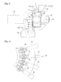
Fig. 1 is a schematic plan view showing the relationship among a cutting/crimping apparatus, a transfer mechanism, and an electric wire holding bar conveying apparatus. -
Fig. 2 is a front view of an electric wire holding bar. -
Fig. 3 is a plane view of the electric wire holding bar. -
Fig. 4 is a side view of the electric wire holding bar. -
Fig. 5 is a partial side view of the electric wire holding bar conveying apparatus showing a bar support in the circulation position. -
Fig. 6 is a view showing the bar support prior to moving to the receiving location. -
Fig. 7 is a partial side view of the electric wire holding bar conveying apparatus showing the bar support in the receiving position. -
Fig. 8 is a view showing the bar support moved to the receiving location. -
Fig. 9 is a plan view showing the circulation chain and bar supports. -
Fig. 10 is a view showing an electric wire holding bar held by a bar support. -
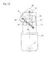
Fig. 11 is a view showing the manner of conveyance in the liner paths. -
Fig. 12 is a view showing how the condition of a position maintaining biasing member is determined by the position of the bar support. - An embodiment of an electric wire holding bar conveying apparatus will be described hereinafter (see
Fig. 1 ). The electric wire holdingbar conveying apparatus 20 is an apparatus for conveying a plurality of electricwire holding bars 10 that hold a plurality ofelectric wires 2 with a terminal(s). - For convenience of description, the manufacturing process of wire harnesses is described first. Wire harnesses are manufactured through a cutting/crimping process, a temporary bundling process, and an assembly process. The cutting/crimping process is a process for manufacturing
electric wires 2 with a terminal by cutting wires to the predetermined length, stripping the ends of the electric wires of the sheathing, and crimping terminals onto the exposed cores. This process can be performed by a cutting/crimping apparatus comprising a measuring mechanism, a cutting mechanism, and a terminal crimping mechanism. The temporary bundling process is a process for manufacturing bundles that are subunits for constituting parts of a wire harness. That is, a wire harness may be formed by combining a plurality of temporary bundles (as well as discreteelectric wires 2 with a terminal). This process manufactures temporary bundles by inserting the terminals of theelectric wire 2 with a terminal into connectors, bundling the electric wires, etc. In addition, intermediate processes are also performed on the electric wires as required. For example, such intermediate processes include crimping special terminals, such as terminals with rubber plugs, etc., removing the sheathing from intermediate sections of the electric wires, splicing, and twisting. The assembly process is a process for assembling temporary bundles andelectric wires 2 with various terminals to routing geometries by bundling these bundles and electric wires to manufacture a completed wire harness. Wire harnesses thus manufactured are incorporated into vehicles and other electrical apparatuses after inspection and other processes. - In the manufacturing process of wire harnesses, the electric wire holding
bar conveying apparatus 20 is used in the step of setting manufacturedelectric wires 2 with a terminal on the electric wire holding bars 10. - The electric wire holding
bar conveying apparatus 20 includes a plurality of bar supports 30, acirculation drive mechanism 60, and a position change mechanism 70 (seeFig. 5 ). The electric wire holdingbar conveying apparatus 20 is installed downstream of a cutting/crimpingapparatus 80 that manufactureselectric wires 2 with a terminal and is configured to convey each electricwire holding bar 10 to a point at which thebar 10 receiveselectric wires 2 with a terminal transferred from the cutting/crimpingapparatus 80 by a transfer mechanism 90 (hereafter "receiving location P") (seeFig. 1 ). - Briefly, the electric wire holding
bar conveying apparatus 20 causes thecirculation drive mechanism 60 to circulate along a circulation path R a plurality of bar supports 30 that support the plurality of electric wire holding bars 10. Furthermore, the electric wire holdingbar conveying apparatus 20 causes theposition change mechanism 70 to place the bar supports 30 in a receiving position at receiving location P (or at a section of the circulation path that contains receiving position P) (seeFig. 8 ) and also place the bar supports 30 in a circulation position elsewhere (seeFigs. 6 and11 ). In the circulation position, the electricwire holding bars 10 occupy less space than in the receiving position. In this way, the electric wire holdingbar conveying apparatus 20 supports and conveys the electricwire holding bars 10 at narrower intervals therebetween, thus reducing the overall area occupied for the number of electric wire holding bars 10 conveyed. - In each electric
wire holding bar 10, a plurality ofelectric wire holders 12 capable of holding the ends ofelectric wires 2 with a terminal are linearly arranged and configured to parallelly hold the ends of the electric wires (seeFigs. 2-4 ). In this embodiment, an end of anelectric wire 2 with a terminal refers to an end portion of the electric wire where the core is covered with sheathing, which is the portion of the electric wire proximally adjacent to the terminal crimped onto the exposed core. More particularly, each electricwire holding bar 10 is formed in a generally elongated shape comprising a plurality ofelectric wire holders 12 and amain bar body 15. - The
electric wire holders 12 are members for holding the ends ofelectric wires 2 with a terminal, each comprising a pair ofelastic pinching pieces 13 and a pinchingpiece fixing portion 14. - The
elastic pinching pieces 13 are formed by blanking and bending sheet metal material to have a flat proximal portion and a distal curvature. More particularly, the flat portion is formed in a plate shape and the curvature continues from the flat portion to form a gentle S-shaped curve. - Each pinching
piece fixing portion 14 is a member made of synthetic resin in an overall shape of an approximate rectangular solid that supports a pair ofelastic pinching pieces 13. The pinchingpiece fixing portion 14 is configured to support a pair ofelastic pinching pieces 13 so that the tips of theelastic pinching pieces 13 are spaced apart from each other with their flat portions abutting on each other (back-to-back). More particularly, each pinchingpiece fixing portion 14 is provided with a recess that opens on one end face through which a pair ofelastic pinching pieces 13 can be fitted in. Formed deep in the pinchingpiece fixing portion 14 are walls that pinch and support a pair ofelastic pinching pieces 13 with their flat portions abutting on each other. Furthermore, the pinchingpiece fixing portion 14 supports the pair of fittedelastic pinching pieces 13 such that portions of the curvatures near their tips come close to each other to leave a gap smaller than the diameter of the electric wire with a terminal (including cases where they come into contact with each other). - Subsequently, by pushing an end of the
electric wire 2 with a terminal between a pair ofelastic pinching pieces 13, the end of the electric wire is held between the portions of the curvatures of the elastic pinching pieces 13close to each other and the opened end face of the pinchingpiece fixing portion 14. - Note that the
electric wire holder 12 is one example and that other configurations may be employed. For example, a configuration may be employed in which the electric wire holders include a comb tooth-like member so that an end of anelectric wire 2 with a terminal can be pushed in between, and hooked on, the teeth of the comb tooth-like member to support the electric wire. - The
main bar body 15 has amain base body 16 and a pair ofend members 18. - The
main base body 16 is formed in a bar shape (a square rod in this case) and the aforementioned plurality ofelectric wire holders 12 are parallelly supported on one side surface of the bar that extends in the longitudinal direction. More specifically, themain base body 16 supports the aforementioned plurality ofelectric wire holders 12 in a manner that aligns theelectric wire holders 12 in the direction in which each pair ofelastic pinching pieces 13 oppose each other. For example, the plurality ofelectric wire holders 12 may advantageously be supported by fitting in themain base body 16 in a convexo-concave manner. Other arrangements may also be employed, such as one where individualelectric wire holders 12 are secured to themain base body 16 with a screw, etc. - In addition, the
main base body 16 has an engagingrecess 17 that opens on one side surface thereof. The engagingrecess 17 is a member for engaging the engagingprotrusion 33 of thebar support 30, to be described below. The engagingrecess 17 is formed in an approximate L-shape that extends from the bottom surface of the main base body 16 (the end opposite to that where theelectric wire holders 12 are supported) toward theelectric wire holders 12 and is bent from the top end toward one end themain base body 16. The engagingrecess 17 is formed in a sufficient size to permit the aforementioned engagingprotrusion 33 to be disposed and moved in the recess (seeFig. 10 ). That is, the engagingprotrusion 33 is inserted into the engagingrecess 17 at its open proximal portion and disposed in its bent top portion. - The pair of
end members 18 is fixed to both longitudinal ends of themain base body 16 with screws, etc. to sandwich the plurality ofelectric wire holders 12 supported on themain base body 16 in the direction of their alignment in order to secure the holders against dislodgement. Moreover, the pair ofend members 18 includes biasing recesses 19 that open at both longitudinal ends of the electricwire holding bar 10. The biasing recesses 19 are members in which the top ends of theanti-dislodgement biasing members 35, to be described below, of thebar support 30 are disposed. In this embodiment, the biasing recesses 19 are formed to have a cylindrical interior space that corresponds to the cylindrical top end shape of theanti-dislodgement biasing members 35 such that these top ends may be disposed in the biasing recesses. - For convenience of description, the cutting/crimping
apparatus 80 and thetransfer mechanism 90 are briefly described. - The cutting/crimping
apparatus 80 includes ameasuring mechanism 82, acutting mechanism 84, aterminal crimping mechanism 86, and a cutting/crimpingtransfer mechanism 88. The measuringmechanism 82 is responsible for measuring and feeding the predetermined length of the electric wire downstream at a time. Thecutting mechanism 84 is provided downstream of themeasuring mechanism 82 for cutting off each predetermined length of the electric wire fed by the measuringmechanism 82 and stripping the sheathing off the ends of the cut-off electric wire. Also, theterminal crimping mechanism 86 is provided downstream of thecutting mechanism 84 for crimping a terminal(s) onto the exposed core of each electric wire cut off at thecutting mechanism 84 and stripped of the sheathing. The cutting/crimpingtransfer mechanism 88 is responsible for gripping the electric wires cut off by thecutting mechanism 84 in the vicinity of both ends (adjacent to the portions stripped of the sheathing that correspond to the ends of theelectric wires 2 with a terminal) and transferring them downstream. The cutting/crimpingtransfer mechanism 88 is configured to transfer the electric wires (theelectric wires 2 with a terminal) to the delivery point for thetransfer mechanism 90 located downstream of the terminal crimpingmechanism 86. - Note that in the foregoing cutting/crimping
apparatus 80,electric wires 2 with a terminal (prior to terminal crimping) are handled to maintain the wire ends approximately in parallel to the horizontal direction. - The
transfer mechanism 90 includes a pairs ofwire grippers 92 and a transfer drive unit 96 (seeFig. 7 ). The wire grippers 92 are configured to grip the ends of anelectric wire 2 with a terminal. Note that also in thetransfer mechanism 90,electric wires 2 with a terminal are handled to maintain the wire ends in approximately parallel to the horizontal direction. Thetransfer drive unit 96 is configured to transfer the pair ofwire grippers 92 between the position where the wire grippers can grip the ends of theelectric wire 2 with a terminal that has been moved to the downstream end of the cutting/crimpingtransfer mechanism 88 or the position where theelectric wire 2 with a terminal is transferred to (gripped by)electric wire holders 12 on the electricwire holding bar 10 of the electric wire holdingbar conveying apparatus 20 positioned at receiving location P, and the positions above these positions. Subsequently, thetransfer drive unit 96 raises the pair ofwire grippers 92 while the pair ofwire grippers 92, which have been transferred to the cutting/crimpingtransfer mechanism 88 by thetransfer drive unit 96, grips an end of theelectric wire 2 with a terminal. In this state, thetransfer drive unit 96 causes the pair ofwire grippers 92 to transfer the ends of theelectric wire 2 with a terminal to the position above theelectric wire holders 12 of the electricwire holding bars 10 for supporting the ends ofelectric wires 2 with a terminal and to lower the wire ends. This causes the ends of theelectric wire 2 with a terminal gripped by the pair ofwire grippers 92 to be also gripped by the predeterminedelectric wire holders 12. Subsequently, the pair ofwire grippers 92 release their grip on theelectric wire 2 with a terminal and are transferred back to the cutting/crimpingtransfer mechanism 88 by thetransfer drive unit 96. - As described above, the electric wire holding
bar conveying apparatus 20 includes a plurality of bar supports 30 and a circulation drive mechanism 60 (seeFig. 5 ). - The bar supports 30 are members for supporting a plurality of electric
wire holding bars 10 and capable of circulating along annular circulation path R (seeFigs. 1 and10 ). The circulation path R is a path that includes outwardly convex curved paths and straight-line paths and, in this embodiment, includes a pair of curved paths of a semicircular shape and a pair of straight-line paths that connects the pair of curved paths. - The
circulation drive mechanism 60 is responsible for circulating the plurality of bar supports 30 along circulation path R (seeFigs. 1 and5 ). Thecirculation drive mechanism 60 includes a pair ofgears 62, acirculation chain 64, and adrive unit 66. - The
gears 62 are a pair of spur gears rotatable about parallel rotating axes and supported on thebase rack 52 at spaced-apart positions in approximately the same plane. One of the pair ofgears 62 is rotatably driven by thedrive unit 66. Thedrive unit 66 may be a motor whose drive shaft is directly coupled to the rotational shaft of one of thegears 62. Alternatively, thedrive unit 66 may be an arrangement that includes a transmission mechanism, such as transmission gears, and a motor, whereby the motor rotates one of thegears 62 via the transmission mechanism. - Moreover, the
annular circulation chain 64 is fitted on the pair ofgears 62. In other words, thecirculation chain 64, fitted on the pair ofgears 62, is run along circulation path R including a pair of semicircular paths along the pair ofgears 62 and a pair of straight-line paths that connects the pair of semicircular paths. In this embodiment, circulation path R lies in a plane approximately parallel to a horizontal plane. The rotation of thedrive unit 66 rotates the pair ofgears 62 and circulates thecirculation chain 64 along circulation path R. In this exemplary description, thecirculation chain 64 is rotated clockwise as seen in a planar view. - However, the
circulation drive mechanism 60 is not limited to the combination of a pair ofgears 62 and thecirculation chain 64. Rather, any arrangement, such as the combination of a pair of pulleys and a driving belt, will suffice as long as it can circulate the plurality of bar supports 30 along circulation path R. - The foregoing plurality (e.g., fifty) of bar supports 30 are supported to the
circulation chain 64 via the support bases 42. More particularly, the plurality of bar supports 30 are provided to support the plurality of electricwire holding bars 10 such that each holdingbar 10 extends outward across circulation path R, and the plurality of bar supports 30 are parallelly arranged at approximately regular intervals along circulation path R. - In a brief overview, the bar supports 30 are supported by the support bases 42 in such a manner that the position of the bar supports 30 can be changed between the circulation position and the receiving position. As used herein, the circulation position refers to the position in which the electric
wire holding bars 10 are supported so that the ends of theelectric wires 2 with a terminal held by theelectric wire holders 12 face vertically upward (seeFigs. 5-6 ). Note that the position in which the ends of theelectric wires 2 with a terminal face vertically upward refers to the position of the electricwire holding bars 10 and that this is not limited to cases where the ends of theelectric wires 2 with a terminal are completely parallel to the vertical. In other words, when this position is assumed, theelectric wire holders 12 of the electric wire bar supports 10 are oriented transversally. In this embodiment, it is assumed that, in the circulation position, the electricwire holding bars 10 support theelectric wire holders 12 in such a way that causes theelectric wire holders 12 to face downstream in circulation path R. Also, the receiving position refers to a position in which the electricwire holding bar 10 is supported so that the ends of theelectric wires 2 with a terminal in theelectric wire holders 12 lie flat and a position in which the wire ends are rotated 90 degrees from the circulation position about rotational axes radially traversing circulation path R (seeFigs. 7-8 ). In other words, when the receiving position is assumed, theelectric wire holders 12 of the electricwire holding bar 10 faces upward. - However, the circulation position and the receiving position of the bar supports 30 are not limited to those in which the direction of the height of the electric wire holding bars 10 is turned horizontal and vertical, respectively. Rather, these positions may also be inclined relative to the horizontal or vertical direction so as to avoid interference between the
electric wires 2 with a terminal held on the electricwire holding bar 10 with those on the adjacent electricwire holding bar 10 or to receive theelectric wires 2 with a terminal from thetransfer mechanism 90. - Each
bar support 30 includes atrough 32, asupport end portion 34, arotational shaft 36, a receivingposition change transmission 38, and a circulation position change transmission 39 (seeFigs. 6 and10 ). Thebar support 30 is an elongated member comprising thetrough 32, thesupport end portion 34, and therotational shaft 36 continuously formed from the distal to proximal ends. - The
trough 32 is formed as an elongated trough in which the bottom portion of one longitudinal end of an electricwire holding bar 10 can be accommodated. More particularly, the gap between the opposing plates of thetrough 32 is set to be the same as or greater (slightly greater in this embodiment) than the thickness dimension of the electric wire holding bar 10 (seeFig. 6 ). Moreover, the longitudinal dimension of thetrough 32 is set to be smaller than that of the electricwire holding bar 10 and its depth dimension of thetrough 32 is set to be smaller than the height dimension of the electric wire holding bar 10 (seeFig. 10 ). Furthermore, the opening of thetrough 32 is formed to flare gradually and outwardly to its edges. This facilitates accommodation of the electricwire holding bar 10 in thetrough 32. Thetrough 32 also includes an engagingprotrusion 33 that can engage the aforementioned engagingrecess 17 of the electric wire holding bar (seeFigs. 4 and10 ). - The
support end portion 34 is a member for positioning the electricwire holding bar 10 by abutting against the end of the electricwire holding bar 10 accommodated in thetrough 32. Thesupport end portion 34 is formed in a rectangular solid to plug the proximal end of thetrough 32. Thesupport end portion 34 includes ananti-dislodgement biasing member 35 capable of biasing the electricwire holding bar 10 in thetrough 32 towards the top end of thetrough 32. - The
anti-dislodgement biasing member 35 includes a base portion protruding from the end of thesupport end portion 34 located on thetrough 32 and an advanceable/retractable portion advanceably and retractably protruding from the top end of the base portion (Fig. 10 ). The advanceable/retractable portion of theanti-dislodgement biasing member 35 is biased in the direction of advancement with respect to the base portion. In this embodiment, theanti-dislodgement biasing member 35 is formed as an approximate cylinder. For example, a plunger in which an advanceable/retractable portion is biased in the direction of advancement by a compression spring may be used as theanti-dislodgement bias member 35. Further, theanti-dislodgement biasing member 35 is formed in a shape that can enter the biasingrecess 19 formed in eitherend member 18 of the electricwire holding bar 10. - When the electric
wire holding bar 10 is accommodated in thetrough 32, theanti-dislodgement biasing member 35 enters the biasingrecess 19 of the electricwire holding bar 10, and the engagingprotrusion 33 of thebar support 30 enters the engagingrecess 17 of the electricwire holding bar 10. At the moment, as the advanceable/retractable portion of theanti-dislodgement biasing member 35 is pressed and retracted by the electricwire holding bar 10, the advanceable/retractable portion is applying pressing force to the electricwire holding bar 10 in the direction of advancement (toward the top end of the trough 32). Once the electricwire holding bar 10 is set on the bottom of thetrough 32, the biasing force of theanti-dislodgement biasing member 35 moves the electricwire holding bar 10 towards the top end of thetrough 32 and the engagingprotrusion 33 moves to the bent top end of the engagingrecess 17, thus engaging the engagingrecess 17. In this way, the electricwire holding bar 10 is supported by thebar support 30 while it is secured against dislodgement from the opening and the top end of thetrough 32. - Each
rotational shaft 36 is a member supported by thesupport base 42 in a manner that allows the rotational shaft to rotate about the axis of rotation (Fig. 5 ). More particularly, therotational shaft 36 is formed in a cylindrical or columnar shape protruding from the proximal end of thesupport end portion 34 in the longitudinal direction of thebar support 30. Moreover, therotational shaft 36 is supported by thesupport base 42 with its center axis extending radially across circulation path R. By virtue of therotational shaft 36 being supported by thesupport base 42, thebar support 30 is rotationally provided around the center axis of therotational shaft 36. - The
support base 42 is a member secured to thecirculation chain 64 to support the bar support 30 (seeFig. 9 ). For example, a chain with attachments may be advantageously used as thecirculation chain 64 such that the support bases 42 are secured with screws, etc., to the brackets provided on the circulation chain. The support bases 42 are secured at approximately regular intervals to thecirculation chain 64 in the direction of its extension. - Each
support base 42 includes asupport hole 43 that rotatably supports therotational shaft 36 of the bar support 30 (Fig. 5 ). Thesupport hole 43 is formed to allow therotational shaft 36 to pass therethrough, more particularly, formed as a through-hole with approximately the same diameter as the outer diameter of therotational shaft 36. Additionally, therotational shaft 36 is rotatably supported while being secured against dislodgement from thesupport hole 43. - The
support base 42 also includes acirculation traveler 46 that stabilizes the position of support of thebar support 30. Thecirculation traveler 46 includes travelingrollers 47 rotatable about axes extending radially across circulation path R. The travelingrollers 47 are provided in contact with flat surfaces of thebase rack 52, on which thecirculation drive mechanism 60 is supported, that extend along the plane in which circulation path R exists. In this embodiment, a pair of travelingrollers 47 is provided. More particularly, one of the travelingrollers 47 is provided in contact with a flat surface outside of and below thecirculation chain 64, whereas the other travelingroller 47 is provided in contact with a flat surface inside of and above thecirculation chain 64. When thebar support 30 is moved along circulation path R, the travelingrollers 47 are in contact with the flat surfaces of thebase rack 52, thus limiting the tilt of thebar support 30 and maintaining the position of thebar support 30. - Note, however, that the inner traveling
roller 47 may be omitted from thecirculation traveler 46. - The
bar support 30 supported by thesupport base 42 is controllably rotated to change between the circulation position and the receiving position. As such a rotation control mechanism, an arrangement may be employed that includes a protrusion provided on the outer periphery of therotational shaft 36 and control pieces provided on thesupport base 42 along the circumferential direction of therotational shaft 36. The control pieces locate the protrusion therebetween and abut against the protrusion when thebar support 30 is in the circulation position and the receiving position (not shown). - Additionally, the
bar support 30 is supported by thesupport base 42 in a manner that maintains thebar support 30 in the circulation position or the receiving position. More particularly, thebar support 30 is coupled to thesupport base 42 via a position maintaining biasing member 48 (seeFigs. 5 and12 ). The position maintaining biasingmember 48 is a tension spring (a coil spring in this embodiment). Provided on the proximal end of therotational shaft 36 is aprojection piece 37 jutting out in one direction from the periphery thereof. Provided at the top end of theprojection piece 37 is a shaft protruding in parallel with the center axis of therotational shaft 36 toward the interior of circulation path R. Thesupport base 42 includes a protrusion that juts out toward the interior of circulation path R from a position opposite the aforementioned shaft across the center axis of therotational shaft 36. Moreover, one end of the position maintaining biasingmember 48 is secured to the shaft provided on theprojection piece 37 while the other end is secured to the protrusion provided on thesupport base 42. The position maintaining biasingmember 48 is maximally extended when thebar support 30 is in an intermediate position between the circulation position and the receiving position. The position maintaining biasingmember 48 is contracted when thebar support 30 is in the circulation position and the receiving position. This means that once in the circulation position or the receiving position, thebar support 30 is maintained in that position unless circumferential force greater than the biasing force of the position maintaining biasingmember 48 acts along the circumference of therotational shaft 36. - The
bar support 30 further includes a receivingposition change transmission 38 and a circulation position change transmission 39 (seeFigs. 6 and8 ). The receivingposition change transmission 38 and the circulationposition change transmission 39 are acted upon by theposition change mechanism 70 when the position of thebar support 30 is changed. - The receiving
position change transmission 38 comes into abutment with a receivingposition change guide 72, to be described below, of theposition change mechanism 70 while thebar support 30 is moved along circulation path R. When in the circulation position, the receivingposition change transmission 38 projects to one side of the rotational shaft 36 (upward in this embodiment) in a direction perpendicular to circulation path R and the rotational axis of therotational shaft 36. More particularly, the receivingposition change transmission 38 is provided on the top end of theprojection piece 37. In this embodiment, the receivingposition change transmission 38 is formed in a shape of a roller rotatably mounted on the shaft on theprojection piece 37. In other words, the receivingposition change transmission 38 includes an outer peripheral surface that surrounds an axis parallel with therotational shaft 36 and comes into abutment with the receivingposition change guide 72. - The circulation
position change transmission 39 comes into abutment with a circulationposition change guide 76, to be described below, of theposition change mechanism 70 while thebar support 30 is moved along circulation path R. When in the receiving position, the circulationposition change transmission 39 protrudes to one side of the rotational shaft 36 (downward in this embodiment) in a direction perpendicular to circulation path R and the rotational axis of therotational shaft 36. In this embodiment, the circulationposition change transmission 39 is formed as a bar (a cylindrical rod in this case) protruding from the outer surface of thesupport end portion 34. In other words, the circulationposition change transmission 39 is provided to project downward from thesupport end portion 34 when thebar support 30 is in the receiving position. More particularly, when thebar support 30 is in the receiving position, the circulationposition change transmission 39 protrudes tiltedly in the upstream direction (slightly, in this embodiment) along circulation path R with respect to the direction connecting the bottom and the opening of thetrough 32 of thebar support 30. - The
position change mechanism 70 is responsible for changing the position of eachbar support 30 between the circulation position and the receiving position by rotating thebar support 30 about the rotational axis of the rotational shaft 36 (seeFigs. 5-8 ). More particularly, theposition change mechanism 70 changes the position of thebar support 30 from the circulation position to the receiving position and from the receiving position to the circulation position in one section of circulation path R (in a curved path, in this embodiment). That section of circulation path R is a range that contains receiving location P. That is, receiving location P, at whichelectric wires 2 with a terminal are transferred onto the electricwire holding bars 10 by thetransfer mechanism 90, is set in a section of a curved path of circulation path R, where electricwire holding bars 10 are spaced apart from adjacent bars at larger intervals than in the straight paths. Theposition change mechanism 70 changes the position of the bar supports 30 to the receiving position at least by receiving location P. - In this embodiment, the
position change mechanism 70 is configured to successively change the position of the bar supports 30 from the circulation position to the receiving position, and then back to the circulation position from the receiving position such that among the plurality of the bar supports 30, the one at receiving position P alone is placed in the receiving position (seeFig. 1 ). In other words, theposition change mechanism 70 changes the position of eachbar support 30 from the circulation position to the receiving position as thebar support 30 moves to receiving location P from the immediately upstream position, and then back to the circulation position from the receiving position as thebar support 30 moves from receiving location P to the immediately downstream position. - The
position change mechanism 70 is configured to transmit the force exerted by thecirculation drive mechanism 60 to move thebar support 30 as rotational force about therotational shaft 36 so as to change the position of thebar support 30. Theposition change mechanism 70 includes a receivingposition change guide 72 and a circulationposition change guide 76. The receivingposition change guide 72 and the circulationposition change guide 76 are provided to change the position of thebar support 30 by abutting against the receivingposition change transmission 38 and the circulationposition change transmission 39, respectively. The receivingposition change guide 72 and the circulationposition change guide 76 are supported directly or indirectly by thebase rack 52. - The receiving
position change guide 72 is provided on the path of movement of the receivingposition change transmission 38 of thebar support 30 when the bar support is in the circulation position (above the path of movement of therotational shaft 36 in this embodiment). Furthermore, the receivingposition change guide 72 is disposed in a location where it does not interfere with the receivingposition change transmission 38 of thebar support 30 when placed in the receiving position. - In this embodiment, the receiving
position change guide 72 is disposed on the path of movement of the receivingposition change transmission 38 of thebar support 30 in the circulation position and has anabutment face 73 that gradually inclines downward from upstream to downstream of circulation path R. It is preferable if theabutment face 73 is provided for rotating thebar support 30 at least until the position maintaining biasingmember 48 biases thebar support 30 over to the receiving position. In other words, theabutment face 73 is formed in such a range (a vertical range) as to allow theabutment face 73 to remain in abutment with the receivingposition change transmission 38 until the line connecting both ends of the position maintaining biasingmember 48 crosses the center axis of therotational shaft 36 to the receiving position side. Furthermore, theabutment face 73 is disposed in a position where theabutment face 73 abuts against the receivingposition change transmission 38 of thebar support 30 in the circulation position while thebar support 30 is moved along circulation path R from the position immediately upstream of receiving location P to receiving location P. Moreover, the receivingposition change guide 72 is configured to change the position of thebar support 30 to the receiving position by the time thebar support 30 reaches receiving location P (including the very moment receiving location P is reached). In other words, the downstream end of theabutment face 73 is provided upstream of receiving location P. - While being circulated in the circulation position, the
bar support 30 gradually assumes the receiving position as the outer peripheral surface of the receivingposition change transmission 38 is brought into abutment against theabutment face 73 of the receivingposition change guide 72 and moved (seeFigs. 6 and8 ). After thebar support 30 is placed in the receiving position, the receivingposition change transmission 38 of thebar support 30 passes under the receivingposition change guide 72 without interfering with thechange guide 72. - The circulation
position change guide 76 is provided on the path of movement of the circulationposition change transmission 39 of thebar support 30 when the bar support is in the receiving position (below the path of movement of therotational shaft 36 in this embodiment). Furthermore, the circulationposition change guide 76 is disposed in a location where it does not interfere with the circulationposition change transmission 39 of thebar support 30 when placed in the circulation position. In this embodiment, the circulationposition change guide 76 is formed in a shape of a roller rotatably supported on a support piece erected on thebase rack 52. More particularly, the circulationposition change guide 76 is rotatably supported about an axis extending radially across circulation path R. - The circulation
position change guide 76 is disposed in a position where theguide 76 abuts against the circulationposition change transmission 39 of thebar support 30 in the receiving position while thebar support 30 is moved along circulation path R from receiving location P to the position immediately downstream of receiving location P. Moreover, in order to change the position of thebar support 30 to the circulation position by the time thebar support 30 reaches the position immediately downstream of receiving location P, the circulationposition change guide 76 is provided upstream of the foregoing downstream position. - While being circulated in the receiving position, the
bar support 30 gradually assumes the circulation position as the circulationposition change transmission 39 is brought into abutment against the outer peripheral surface of the circulationposition change guide 76 and moved (seeFig. 8 ). After thebar support 30 is placed in the circulation position, the circulationposition change transmission 39 of thebar support 30 passes over the circulationposition change guide 76 without interfering with thechange guide 76. - The following describes the operation of the electric wire holding
bar conveying apparatus 20. - It is assumed that initially, the plurality of bar supports 30 support an electric
wire holding bar 10. In this state, the plurality of electricwire holding bars 10 are conveyed along circulation path R by the operation of thecirculation drive mechanism 60. - If any of the electric wire holding bars 10 is set in place at receiving location P, the conveyance is suspended. The position of the
bar support 30 is changed from the circulation position to the receiving position by theposition change mechanism 70 while this electricwire holding bar 10 is moved to receiving location P from the position immediately upstream thereof. - In this state, an
electric wire 2 with a terminal manufactured by the cutting/crimpingapparatus 80 is transferred by thetransfer mechanism 90 onto the electricwire holding bar 10 held by thebar support 30 now placed in the receiving position at receiving location P. Once the predetermined number and types ofelectric wires 2 with a terminal are transferred onto the electricwire holding bar 10, thecirculation drive mechanism 60 is operated to convey the plurality of the electricwire holding bars 10 so as to set the immediately upstream bar support 30 (electric wire holding bar 10) at receiving location P. At this point, the position of thebar support 30 is changed from the receiving position to the circulation position, halfway through that conveyance from receiving location P to the position immediately downstream thereof. - Subsequently,
electric wires 2 with a terminal are transferred to the electricwire holding bar 10 set at receiving location P in the same manner as described above. - The
electric wires 2 with a terminal may be transferred to theelectric wire holders 12 of the electricwire holding bar 10 all at once during a single stop of the holding bar at receiving position P or during each stop in multiple circulations of the holding bar. In the latter case, a different type ofelectric wire 2 with a terminal may be transferred each time the electricwire holding bar 10 stops at receiving location P. - Once the transfer of
electric wires 2 with a terminal onto the electricwire holding bar 10 of eachbar support 30 is completed, the electricwire holding bars 10 are removed from the bar supports 30. This provides electricwire holding bars 10 each carrying different types or the same type ofelectric wires 2 with a terminal. Alternatively, if different types ofelectric wires 2 with a terminal constituting a temporary bundle are held by each electricwire holding bar 10, a plurality of electricwire holding bars 10 holding a plurality ofelectric wires 2 with a terminal for a temporary bundle may be provided. - According to the electric wire holding
bar conveying apparatus 20 thus constructed, the position of a plurality of bar supports 30 can be changed between the circulation position that supports the electricwire holding bars 10 such that the ends of theelectric wires 2 with a terminal held by theelectric wire holders 12 face vertically upward and the receiving position that supports the electricwire holding bars 10 such that the ends of theelectric wires 2 with a terminal are laid flat. Eachbar support 30 is configured to be rotated about the rotational axis of therotational shaft 36 in a section of circulation path R by theposition change mechanism 70 to change its position from the circulation position to the receiving position and from the receiving position to the circulation position. Accordingly, tangling up ofelectric wires 2 with a terminal held by adjacent electricwire holding bars 10 can be minimized while interference betweenelectric wires 2 with a terminal and electricwire holding bars 10 can be also minimized. This allows a plurality of electricwire holding bars 10 to be arranged at smaller intervals on circulation path R, thus enabling conveyance of the plurality of electricwire holding bars 10 in a maximally space-saving manner. - Additionally, as the
position change mechanism 70 is configured to transmit the force exerted by thecirculation drive mechanism 60 to move thebar support 30 along circulation path R as rotational force about the rotational axis of therotational shaft 36 to change the position of thebar support 30, this realizes the arrangement for changing the position of thebar support 30 without providing a separate driving source. - Each
bar support 30 includes a receivingposition change transmission 38 that projects to one side of the rotational axis of therotational shaft 36 in a direction perpendicular to circulation path R and the rotational axis when thebar support 30 is in the circulation position and a circulationposition change transmission 39 that projects to one side of the rotational axis of therotational shaft 36 in a direction perpendicular to circulation path R and the rotational axis when thetransmission 39 is in the receiving position. Theposition change mechanism 70 includes a receivingposition change guide 72 provided on the path of movement of the receivingposition change transmission 38 of eachbar support 30 when the bar support is in the circulation position and a circulationposition change guide 76 provided on the path of movement of the circulationposition change transmission 39 of eachbar support 30 when the bar support is in the receiving position. Accordingly, while being circulated by thecirculation drive mechanism 60, the position of thebar support 30 is changed from the circulation position to the receiving position by the receivingposition change transmission 38 coming into abutment with the receivingposition change guide 72, and the position of thebar support 30 is changed from the receiving position to the circulation position by the circulationposition change transmission 39 coming into abutment with the circulationposition change guide 76. In this way, the position of thebar support 30 can be changed with a simple structure. - Moreover, as circulation path R is configured as a path that includes straight-line paths, even in the straight-line paths where the intervals between adjacent electric
wire holding bars 10 are smaller than in the curved paths, tangling up, etc., of theelectric wires 2 with a terminal held by adjacent electricwire holding bars 10 can be minimized, thus conveying a plurality of electricwire holding bars 10 in a more space-saving manner. In other words, this can reduce the occupied area for the predetermined number of electricwire holding bars 10 to be conveyed. - Although the dimension of each electric
wire holding bar 10 along circulation path R is smaller when thebar support 30 is in the receiving position than in the circulation position, the overall dimension of the electricwire holding bar 10 andelectric wires 2 with a terminal held thereby is smaller when thebar support 30 is in the circulation position than in the receiving position. - Furthermore, as circulation path R includes a pair of curved paths of a semicircular shape and a pair of straight-line paths that connects the pair of curved paths, the plurality of electric
wire holding bars 10 can be conveyed in a still more space-saving manner. - Moreover, since the
position change mechanism 70 successively changes the position of the plurality of bar supports 30 from the circulation position to the receiving position and from the receiving position to the circulation position as they are moved by thecirculation drive mechanism 60 such that only onebar support 30 is in the receiving position at any moment, only thebar support 30 placed in the location whereelectric wires 2 with a terminal are transferred to the electric wire holding bars 10 is set in the receiving position such that tangling up, etc., ofelectric wires 2 with a terminal held by adjacent electricwire holding bars 10 can be minimized more reliably. - An example in which circulation path R includes a pair of curved paths of a semicircular shape and a pair of straight-line paths that connects the pair of curved paths has been described so far. However, circulation path R may be any other type of circulation path. Although receiving location P is set in a section of a curved path in the described example, receiving location P may be set in a section of the straight-line paths.
- Further, the
position change mechanism 70 is not limited to the configuration for changing the position of only thebar support 30 moved to receiving location P to the receiving position. That is, theposition change mechanism 70 may alternatively be configured to change the position of the bar supports 30 that has been moved into a section of circulation path R that contains receiving location P to the receiving position. It is preferred, however, that the electricwire holding bar 10 whose position is to be changed to the receiving position be in a curved path of circulation path R, where the gaps between electricwire holding bars 10 are greater than in the straight-line paths. More preferably, only the onebar support 30 moved to receiving location P is placed in the receiving position as this can more reliably limit tangling up ofelectric wires 2 with a terminal held in adjacent electric wire holding bars 10. - Further, the
position change mechanism 70 is not limited to the foregoing configuration; rather, it will suffice as long as themechanism 70 is capable of changing the position of the bar supports 30 between the circulation position and the receiving position. For example, the position change mechanism may have a configuration in which a receiving position change guide and a circulation position change guide are disposed one of above and below the rotational axis of therotational shaft 36. That is, each bar support may be provided with a receiving position change transmission that projects above therotational shaft 36 when in the circulation position and a circulation position change transmission that projects above therotational shaft 36 when in the receiving position, wherein these transmissions change from the circulation position to the receiving position and from the receiving position to the circulation position by coming into abutment against the receiving position change guide or the circulation position change guide provided above therotational shaft 36. It is preferred that, of the transmissions provided on circulation path R, the one that is moved about the rotational axis of therotational shaft 36 in the downstream direction in circulation path R by its position change guide be preferably formed in a shape that extends obliquely downstream and that the position change guide against which this transmission abuts be set at a relatively obtuse oblique angle. - Moreover, for example, the
position change mechanism 70 may have the following configuration: that is, each bar support may be provided with a transmission that projects to one side of the rotational axis of therotational shaft 36 in a direction perpendicular to circulation path R and the rotational axis when the bar support is in the circulation position. Additionally, the foregoing bar support may be coupled to thesupport base 42 with a biasing member that biases the bar support in the rotational direction to place the bar support in the circulation position. Furthermore, a position change guide may be provided on the path of movement of the transmission. The position change guide includes a position change surface that is provided on, and intersects, the path of movement of the transmission of the bar support in the circulation position and a regulating surface that is capable of abutting against the transmission of the bar support placed in the receiving position at the receiving location and provided in a plane along circulation path R. As the bar support is moved to the receiving location, the transmission abuts against the position change surface to change the position of the bar support and the transmission abuts against the regulation surface at the receiving location to prevent the bar support from changing its position to the circulation position. When the transmission is moved to a location where it is no longer in contact with the regulation surface, the position of the bar support is changed to the circulation position by the biasing force of the biasing member. - In addition, the position change mechanism may be configured to change the position of each
bar support 30 moved to receiving location P by rotatably driving the bar support with a motor. - Having described the electric wire holding
bar conveying apparatus 20 in detail, the foregoing description is illustrative in all aspects and the present invention is not limited thereto. It is understood that countless variants not illustrated herein are conceivable without deviating from the scope of the present invention. -
- 2
- Electric wire with a terminal
- 10
- Electric wire holding bar
- 12
- Electric wire holder
- 20
- Electric wire holding bar conveying apparatus
- 30
- Bar support
- 38
- Receiving position change transmission
- 39
- Circulation position change transmission
- 60
- Circulation drive mechanism
- 70
- Position change mechanism
- 72
- Receiving position change guide
- 76
- Circulation position change guide
- P
- Receiving location
- R
- Circulation path
Claims (6)
- An electric wire holding bar conveying apparatus for conveying a plurality of electric wire holding bars on which a plurality of electric wire holders capable of holding ends of electric wires with a terminal are linearly arranged, the electric wire holding bars being capable of holding the ends of the electric wires in parallel, a terminal being crimped onto an end of the electric wires, the apparatus comprising:a plurality of bar supports capable of supporting the plurality of electric wire holding bars such that each electric wire holding bar extends outward with respect to a circulation path, the plurality of bar supports being capable of changing their position between a circulation position in which the electric wire holding bars are supported such that the ends of the electric wires with a terminal held by the electric wire holders face vertically upward and a receiving position in which the electric wire holding bars are supported such that the ends of the electric wires with a terminal held by the electric wire holders are laid flat;a circulation drive mechanism for circulating the plurality of bar supports along the circulation path; anda position change mechanism that rotates each bar support about a rotational axis in a section of the circulation path to change its position from the circulation position to the receiving position and from the receiving position to the circulation position.
- An electric wire holding bar conveying apparatus according to claim 1,
wherein the position change mechanism transmits the force exerted by the circulation drive mechanism to move the bar supports along the circulation path as rotational force about the rotational axes to change the position of the bar supports. - An electric wire holding bar conveying apparatus according to claim 1 or 2,
wherein each bar support includes a receiving position change transmission that projects to one side of the rotational axis of the bar support in a direction perpendicular to the circulation path and the rotational axis when the bar support is in the circulation position, and a circulation position change transmission that projects to one side of the rotational axis of the bar support in a direction perpendicular to the circulation path and the rotational axis when the bar support is in the receiving position, and
wherein the position change mechanism includes a receiving position change guide provided on a path of movement of the receiving position change transmission of the bar support in the circulation position and a circulation position change guide provided on a path of movement of the circulation position change transmission of the bar support in the receiving position. - An electric wire holding bar conveying apparatus according to any one of claims 1-3,
wherein the circulation path includes straight-line paths. - An electric wire holding bar conveying apparatus according to claim 4,
wherein the circulation path includes a pair of curved paths of a semicircular shape and a pair of straight-line paths that connects the pair of curved paths. - An electric wire holding bar conveying apparatus according to any one of claims 1-5,
wherein the position change mechanism successively changes the position of the bar supports from the circulation position to the receiving position and from the receiving position to the circulation position as the plurality of bar supports are moved by the circulation drive mechanism such that only one bar support is in the receiving position at any moment.
Applications Claiming Priority (2)
| Application Number | Priority Date | Filing Date | Title |
|---|---|---|---|
| JP2012013209A JP5842631B2 (en) | 2012-01-25 | 2012-01-25 | Electric wire holding bar conveyor |
| PCT/JP2012/069086 WO2013111369A1 (en) | 2012-01-25 | 2012-07-27 | Electrical wire holding bar conveying device |
Publications (3)
| Publication Number | Publication Date |
|---|---|
| EP2790191A1 true EP2790191A1 (en) | 2014-10-15 |
| EP2790191A4 EP2790191A4 (en) | 2015-05-27 |
| EP2790191B1 EP2790191B1 (en) | 2016-03-02 |
Family
ID=48873119
Family Applications (1)
| Application Number | Title | Priority Date | Filing Date |
|---|---|---|---|
| EP12866506.4A Not-in-force EP2790191B1 (en) | 2012-01-25 | 2012-07-27 | Electrical wire holding bar conveying device |
Country Status (4)
| Country | Link |
|---|---|
| EP (1) | EP2790191B1 (en) |
| JP (1) | JP5842631B2 (en) |
| CN (1) | CN104054144B (en) |
| WO (1) | WO2013111369A1 (en) |
Cited By (3)
| Publication number | Priority date | Publication date | Assignee | Title |
|---|---|---|---|---|
| EP3086329A4 (en) * | 2013-12-18 | 2017-01-04 | Sumitomo Wiring Systems, Ltd. | Wire ejection device |
| US10766733B2 (en) | 2017-03-08 | 2020-09-08 | Yazaki Corporation | Electric wire processing apparatus, electric wire processing method, and electric wire holding structure |
| US10854358B2 (en) | 2016-05-31 | 2020-12-01 | Yazaki Corporation | Wire harness manufacturing method and wire harness manufacturing device |
Families Citing this family (1)
| Publication number | Priority date | Publication date | Assignee | Title |
|---|---|---|---|---|
| JP2017073311A (en) * | 2015-10-08 | 2017-04-13 | 株式会社オートネットワーク技術研究所 | Multistage wire holding bar |
Family Cites Families (5)
| Publication number | Priority date | Publication date | Assignee | Title |
|---|---|---|---|---|
| JP3892919B2 (en) * | 1996-10-03 | 2007-03-14 | 矢崎総業株式会社 | Wire harness manufacturing method and manufacturing apparatus |
| JP2001232144A (en) * | 2000-02-28 | 2001-08-28 | Seiden Kogyo:Kk | Organic gas deodorizing method and utilization device |
| JP2001332144A (en) * | 2000-05-23 | 2001-11-30 | Sumitomo Wiring Syst Ltd | Wire joint holder and stock truck |
| JP2003138828A (en) * | 2001-10-30 | 2003-05-14 | Sun Wave Ind Co Ltd | Guide device for mobile body of cabinet |
| JP4985713B2 (en) * | 2009-06-10 | 2012-07-25 | 住友電装株式会社 | Electric wire holding bar conveying device and electric wire set manufacturing method |
-
2012
- 2012-01-25 JP JP2012013209A patent/JP5842631B2/en not_active Expired - Fee Related
- 2012-07-27 CN CN201280067369.3A patent/CN104054144B/en not_active Expired - Fee Related
- 2012-07-27 EP EP12866506.4A patent/EP2790191B1/en not_active Not-in-force
- 2012-07-27 WO PCT/JP2012/069086 patent/WO2013111369A1/en not_active Ceased
Cited By (3)
| Publication number | Priority date | Publication date | Assignee | Title |
|---|---|---|---|---|
| EP3086329A4 (en) * | 2013-12-18 | 2017-01-04 | Sumitomo Wiring Systems, Ltd. | Wire ejection device |
| US10854358B2 (en) | 2016-05-31 | 2020-12-01 | Yazaki Corporation | Wire harness manufacturing method and wire harness manufacturing device |
| US10766733B2 (en) | 2017-03-08 | 2020-09-08 | Yazaki Corporation | Electric wire processing apparatus, electric wire processing method, and electric wire holding structure |
Also Published As
| Publication number | Publication date |
|---|---|
| EP2790191B1 (en) | 2016-03-02 |
| CN104054144A (en) | 2014-09-17 |
| WO2013111369A1 (en) | 2013-08-01 |
| JP5842631B2 (en) | 2016-01-13 |
| CN104054144B (en) | 2016-07-06 |
| EP2790191A4 (en) | 2015-05-27 |
| JP2013152856A (en) | 2013-08-08 |
Similar Documents
| Publication | Publication Date | Title |
|---|---|---|
| KR101643061B1 (en) | Wire straightening apparatus | |
| CN101335121B (en) | Electric wire delivery apparatus and electric wire sizing-cutting apparatus including the same | |
| EP3065241A1 (en) | Power line correcting device | |
| EP2790191B1 (en) | Electrical wire holding bar conveying device | |
| JP5817576B2 (en) | Wire transfer device | |
| US9124058B2 (en) | Feeding wire-ends to processing units | |
| KR20180098295A (en) | Pincers | |
| US11495933B2 (en) | Assembly system | |
| US20190115734A1 (en) | Conductor positioning fixture for cable processing | |
| CN104662783A (en) | Winding device and winding method | |
| CN108573777A (en) | Wire processing apparatus, electric wire processing method and electric wire holding structure | |
| US20040143966A1 (en) | Method and apparatus for equipping plug housings with fitted-out cable ends of a cable | |
| JP2022048177A (en) | Terminal processing method for in-vehicle cables and their devices | |
| US11569716B2 (en) | Coil forming apparatus and coil forming method | |
| US11735984B2 (en) | Coil forming apparatus and coil forming method | |
| US11999586B2 (en) | Wire handling device | |
| JP2018187650A (en) | Straightening device for coated stranded wire | |
| US20220285092A1 (en) | Coil forming apparatus and coil forming method | |
| CN110660526A (en) | Winding unit and manufacturing method of spiral wire | |
| US10532531B2 (en) | Device for winding bead ring-binding thread | |
| JP7014700B2 (en) | Coil forming method and coil forming equipment | |
| US20250023313A1 (en) | Core wire alignment apparatus for multi-core cable | |
| US20250246343A1 (en) | Installation designed as a pivot machine for assembling cables | |
| WO2025104465A1 (en) | System and method for straightening electrical cables | |
| CN117649981A (en) | Methods and apparatus for orienting multi-core wire-like materials |
Legal Events
| Date | Code | Title | Description |
|---|---|---|---|
| PUAI | Public reference made under article 153(3) epc to a published international application that has entered the european phase |
Free format text: ORIGINAL CODE: 0009012 |
|
| 17P | Request for examination filed |
Effective date: 20140710 |
|
| AK | Designated contracting states |
Kind code of ref document: A1 Designated state(s): AL AT BE BG CH CY CZ DE DK EE ES FI FR GB GR HR HU IE IS IT LI LT LU LV MC MK MT NL NO PL PT RO RS SE SI SK SM TR |
|
| DAX | Request for extension of the european patent (deleted) | ||
| RA4 | Supplementary search report drawn up and despatched (corrected) |
Effective date: 20150428 |
|
| RIC1 | Information provided on ipc code assigned before grant |
Ipc: H01B 13/012 20060101AFI20150421BHEP |
|
| GRAP | Despatch of communication of intention to grant a patent |
Free format text: ORIGINAL CODE: EPIDOSNIGR1 |
|
| INTG | Intention to grant announced |
Effective date: 20151106 |
|
| GRAS | Grant fee paid |
Free format text: ORIGINAL CODE: EPIDOSNIGR3 |
|
| GRAA | (expected) grant |
Free format text: ORIGINAL CODE: 0009210 |
|
| AK | Designated contracting states |
Kind code of ref document: B1 Designated state(s): AL AT BE BG CH CY CZ DE DK EE ES FI FR GB GR HR HU IE IS IT LI LT LU LV MC MK MT NL NO PL PT RO RS SE SI SK SM TR |
|
| REG | Reference to a national code |
Ref country code: GB Ref legal event code: FG4D |
|
| REG | Reference to a national code |
Ref country code: AT Ref legal event code: REF Ref document number: 778516 Country of ref document: AT Kind code of ref document: T Effective date: 20160315 Ref country code: CH Ref legal event code: EP |
|
| REG | Reference to a national code |
Ref country code: IE Ref legal event code: FG4D |
|
| REG | Reference to a national code |
Ref country code: CH Ref legal event code: NV Representative=s name: HEPP WENGER RYFFEL AG, CH |
|
| REG | Reference to a national code |
Ref country code: DE Ref legal event code: R096 Ref document number: 602012015329 Country of ref document: DE |
|
| REG | Reference to a national code |
Ref country code: FR Ref legal event code: PLFP Year of fee payment: 5 |
|
| REG | Reference to a national code |
Ref country code: NL Ref legal event code: MP Effective date: 20160302 |
|
| REG | Reference to a national code |
Ref country code: LT Ref legal event code: MG4D |
|
| REG | Reference to a national code |
Ref country code: AT Ref legal event code: MK05 Ref document number: 778516 Country of ref document: AT Kind code of ref document: T Effective date: 20160302 |
|
| PG25 | Lapsed in a contracting state [announced via postgrant information from national office to epo] |
Ref country code: HR Free format text: LAPSE BECAUSE OF FAILURE TO SUBMIT A TRANSLATION OF THE DESCRIPTION OR TO PAY THE FEE WITHIN THE PRESCRIBED TIME-LIMIT Effective date: 20160302 Ref country code: ES Free format text: LAPSE BECAUSE OF FAILURE TO SUBMIT A TRANSLATION OF THE DESCRIPTION OR TO PAY THE FEE WITHIN THE PRESCRIBED TIME-LIMIT Effective date: 20160302 Ref country code: FI Free format text: LAPSE BECAUSE OF FAILURE TO SUBMIT A TRANSLATION OF THE DESCRIPTION OR TO PAY THE FEE WITHIN THE PRESCRIBED TIME-LIMIT Effective date: 20160302 Ref country code: GR Free format text: LAPSE BECAUSE OF FAILURE TO SUBMIT A TRANSLATION OF THE DESCRIPTION OR TO PAY THE FEE WITHIN THE PRESCRIBED TIME-LIMIT Effective date: 20160603 Ref country code: NO Free format text: LAPSE BECAUSE OF FAILURE TO SUBMIT A TRANSLATION OF THE DESCRIPTION OR TO PAY THE FEE WITHIN THE PRESCRIBED TIME-LIMIT Effective date: 20160602 |
|
| PG25 | Lapsed in a contracting state [announced via postgrant information from national office to epo] |
Ref country code: AT Free format text: LAPSE BECAUSE OF FAILURE TO SUBMIT A TRANSLATION OF THE DESCRIPTION OR TO PAY THE FEE WITHIN THE PRESCRIBED TIME-LIMIT Effective date: 20160302 Ref country code: SE Free format text: LAPSE BECAUSE OF FAILURE TO SUBMIT A TRANSLATION OF THE DESCRIPTION OR TO PAY THE FEE WITHIN THE PRESCRIBED TIME-LIMIT Effective date: 20160302 Ref country code: NL Free format text: LAPSE BECAUSE OF FAILURE TO SUBMIT A TRANSLATION OF THE DESCRIPTION OR TO PAY THE FEE WITHIN THE PRESCRIBED TIME-LIMIT Effective date: 20160302 Ref country code: RS Free format text: LAPSE BECAUSE OF FAILURE TO SUBMIT A TRANSLATION OF THE DESCRIPTION OR TO PAY THE FEE WITHIN THE PRESCRIBED TIME-LIMIT Effective date: 20160302 Ref country code: LV Free format text: LAPSE BECAUSE OF FAILURE TO SUBMIT A TRANSLATION OF THE DESCRIPTION OR TO PAY THE FEE WITHIN THE PRESCRIBED TIME-LIMIT Effective date: 20160302 Ref country code: PL Free format text: LAPSE BECAUSE OF FAILURE TO SUBMIT A TRANSLATION OF THE DESCRIPTION OR TO PAY THE FEE WITHIN THE PRESCRIBED TIME-LIMIT Effective date: 20160302 Ref country code: LT Free format text: LAPSE BECAUSE OF FAILURE TO SUBMIT A TRANSLATION OF THE DESCRIPTION OR TO PAY THE FEE WITHIN THE PRESCRIBED TIME-LIMIT Effective date: 20160302 |
|
| PG25 | Lapsed in a contracting state [announced via postgrant information from national office to epo] |
Ref country code: IS Free format text: LAPSE BECAUSE OF FAILURE TO SUBMIT A TRANSLATION OF THE DESCRIPTION OR TO PAY THE FEE WITHIN THE PRESCRIBED TIME-LIMIT Effective date: 20160702 Ref country code: EE Free format text: LAPSE BECAUSE OF FAILURE TO SUBMIT A TRANSLATION OF THE DESCRIPTION OR TO PAY THE FEE WITHIN THE PRESCRIBED TIME-LIMIT Effective date: 20160302 |
|
| PG25 | Lapsed in a contracting state [announced via postgrant information from national office to epo] |
Ref country code: RO Free format text: LAPSE BECAUSE OF FAILURE TO SUBMIT A TRANSLATION OF THE DESCRIPTION OR TO PAY THE FEE WITHIN THE PRESCRIBED TIME-LIMIT Effective date: 20160302 Ref country code: CZ Free format text: LAPSE BECAUSE OF FAILURE TO SUBMIT A TRANSLATION OF THE DESCRIPTION OR TO PAY THE FEE WITHIN THE PRESCRIBED TIME-LIMIT Effective date: 20160302 Ref country code: SK Free format text: LAPSE BECAUSE OF FAILURE TO SUBMIT A TRANSLATION OF THE DESCRIPTION OR TO PAY THE FEE WITHIN THE PRESCRIBED TIME-LIMIT Effective date: 20160302 Ref country code: PT Free format text: LAPSE BECAUSE OF FAILURE TO SUBMIT A TRANSLATION OF THE DESCRIPTION OR TO PAY THE FEE WITHIN THE PRESCRIBED TIME-LIMIT Effective date: 20160704 Ref country code: SM Free format text: LAPSE BECAUSE OF FAILURE TO SUBMIT A TRANSLATION OF THE DESCRIPTION OR TO PAY THE FEE WITHIN THE PRESCRIBED TIME-LIMIT Effective date: 20160302 |
|
| REG | Reference to a national code |
Ref country code: DE Ref legal event code: R097 Ref document number: 602012015329 Country of ref document: DE |
|
| PG25 | Lapsed in a contracting state [announced via postgrant information from national office to epo] |
Ref country code: BE Free format text: LAPSE BECAUSE OF FAILURE TO SUBMIT A TRANSLATION OF THE DESCRIPTION OR TO PAY THE FEE WITHIN THE PRESCRIBED TIME-LIMIT Effective date: 20160302 |
|
| PLBE | No opposition filed within time limit |
Free format text: ORIGINAL CODE: 0009261 |
|
| STAA | Information on the status of an ep patent application or granted ep patent |
Free format text: STATUS: NO OPPOSITION FILED WITHIN TIME LIMIT |
|
| PG25 | Lapsed in a contracting state [announced via postgrant information from national office to epo] |
Ref country code: DK Free format text: LAPSE BECAUSE OF FAILURE TO SUBMIT A TRANSLATION OF THE DESCRIPTION OR TO PAY THE FEE WITHIN THE PRESCRIBED TIME-LIMIT Effective date: 20160302 |
|
| 26N | No opposition filed |
Effective date: 20161205 |
|
| PG25 | Lapsed in a contracting state [announced via postgrant information from national office to epo] |
Ref country code: SI Free format text: LAPSE BECAUSE OF FAILURE TO SUBMIT A TRANSLATION OF THE DESCRIPTION OR TO PAY THE FEE WITHIN THE PRESCRIBED TIME-LIMIT Effective date: 20160302 Ref country code: BG Free format text: LAPSE BECAUSE OF FAILURE TO SUBMIT A TRANSLATION OF THE DESCRIPTION OR TO PAY THE FEE WITHIN THE PRESCRIBED TIME-LIMIT Effective date: 20160602 |
|
| PG25 | Lapsed in a contracting state [announced via postgrant information from national office to epo] |
Ref country code: MC Free format text: LAPSE BECAUSE OF FAILURE TO SUBMIT A TRANSLATION OF THE DESCRIPTION OR TO PAY THE FEE WITHIN THE PRESCRIBED TIME-LIMIT Effective date: 20160302 |
|
| REG | Reference to a national code |
Ref country code: IE Ref legal event code: MM4A |
|
| REG | Reference to a national code |
Ref country code: FR Ref legal event code: PLFP Year of fee payment: 6 |
|
| PG25 | Lapsed in a contracting state [announced via postgrant information from national office to epo] |
Ref country code: IE Free format text: LAPSE BECAUSE OF NON-PAYMENT OF DUE FEES Effective date: 20160727 |
|
| PG25 | Lapsed in a contracting state [announced via postgrant information from national office to epo] |
Ref country code: LU Free format text: LAPSE BECAUSE OF NON-PAYMENT OF DUE FEES Effective date: 20160727 |
|
| PG25 | Lapsed in a contracting state [announced via postgrant information from national office to epo] |
Ref country code: HU Free format text: LAPSE BECAUSE OF FAILURE TO SUBMIT A TRANSLATION OF THE DESCRIPTION OR TO PAY THE FEE WITHIN THE PRESCRIBED TIME-LIMIT; INVALID AB INITIO Effective date: 20120727 |
|
| REG | Reference to a national code |
Ref country code: FR Ref legal event code: PLFP Year of fee payment: 7 |
|
| PG25 | Lapsed in a contracting state [announced via postgrant information from national office to epo] |
Ref country code: CY Free format text: LAPSE BECAUSE OF FAILURE TO SUBMIT A TRANSLATION OF THE DESCRIPTION OR TO PAY THE FEE WITHIN THE PRESCRIBED TIME-LIMIT Effective date: 20160302 Ref country code: MK Free format text: LAPSE BECAUSE OF FAILURE TO SUBMIT A TRANSLATION OF THE DESCRIPTION OR TO PAY THE FEE WITHIN THE PRESCRIBED TIME-LIMIT Effective date: 20160302 Ref country code: MT Free format text: LAPSE BECAUSE OF NON-PAYMENT OF DUE FEES Effective date: 20160731 |
|
| PG25 | Lapsed in a contracting state [announced via postgrant information from national office to epo] |
Ref country code: TR Free format text: LAPSE BECAUSE OF FAILURE TO SUBMIT A TRANSLATION OF THE DESCRIPTION OR TO PAY THE FEE WITHIN THE PRESCRIBED TIME-LIMIT Effective date: 20160302 Ref country code: AL Free format text: LAPSE BECAUSE OF FAILURE TO SUBMIT A TRANSLATION OF THE DESCRIPTION OR TO PAY THE FEE WITHIN THE PRESCRIBED TIME-LIMIT Effective date: 20160302 |
|
| PGFP | Annual fee paid to national office [announced via postgrant information from national office to epo] |
Ref country code: FR Payment date: 20200611 Year of fee payment: 9 |
|
| PGFP | Annual fee paid to national office [announced via postgrant information from national office to epo] |
Ref country code: DE Payment date: 20200714 Year of fee payment: 9 Ref country code: GB Payment date: 20200716 Year of fee payment: 9 |
|
| PGFP | Annual fee paid to national office [announced via postgrant information from national office to epo] |
Ref country code: CH Payment date: 20200716 Year of fee payment: 9 Ref country code: IT Payment date: 20200610 Year of fee payment: 9 |
|
| REG | Reference to a national code |
Ref country code: DE Ref legal event code: R119 Ref document number: 602012015329 Country of ref document: DE |
|
| REG | Reference to a national code |
Ref country code: CH Ref legal event code: PL |
|
| GBPC | Gb: european patent ceased through non-payment of renewal fee |
Effective date: 20210727 |
|
| PG25 | Lapsed in a contracting state [announced via postgrant information from national office to epo] |
Ref country code: LI Free format text: LAPSE BECAUSE OF NON-PAYMENT OF DUE FEES Effective date: 20210731 Ref country code: GB Free format text: LAPSE BECAUSE OF NON-PAYMENT OF DUE FEES Effective date: 20210727 Ref country code: DE Free format text: LAPSE BECAUSE OF NON-PAYMENT OF DUE FEES Effective date: 20220201 Ref country code: CH Free format text: LAPSE BECAUSE OF NON-PAYMENT OF DUE FEES Effective date: 20210731 |
|
| PG25 | Lapsed in a contracting state [announced via postgrant information from national office to epo] |
Ref country code: FR Free format text: LAPSE BECAUSE OF NON-PAYMENT OF DUE FEES Effective date: 20210731 |
|
| PG25 | Lapsed in a contracting state [announced via postgrant information from national office to epo] |
Ref country code: IT Free format text: LAPSE BECAUSE OF NON-PAYMENT OF DUE FEES Effective date: 20210727 |