EP2790173A1 - Display device - Google Patents
Display device Download PDFInfo
- Publication number
- EP2790173A1 EP2790173A1 EP20140163978 EP14163978A EP2790173A1 EP 2790173 A1 EP2790173 A1 EP 2790173A1 EP 20140163978 EP20140163978 EP 20140163978 EP 14163978 A EP14163978 A EP 14163978A EP 2790173 A1 EP2790173 A1 EP 2790173A1
- Authority
- EP
- European Patent Office
- Prior art keywords
- backlight
- area
- direct
- type
- disposed
- Prior art date
- Legal status (The legal status is an assumption and is not a legal conclusion. Google has not performed a legal analysis and makes no representation as to the accuracy of the status listed.)
- Ceased
Links
- 230000003287 optical effect Effects 0.000 claims description 20
- 238000010586 diagram Methods 0.000 description 25
- 239000004973 liquid crystal related substance Substances 0.000 description 25
- 238000000034 method Methods 0.000 description 6
- 239000000758 substrate Substances 0.000 description 6
- 238000009792 diffusion process Methods 0.000 description 2
- 230000000694 effects Effects 0.000 description 2
- 230000001360 synchronised effect Effects 0.000 description 2
Images





Classifications
-
- G—PHYSICS
- G02—OPTICS
- G02F—OPTICAL DEVICES OR ARRANGEMENTS FOR THE CONTROL OF LIGHT BY MODIFICATION OF THE OPTICAL PROPERTIES OF THE MEDIA OF THE ELEMENTS INVOLVED THEREIN; NON-LINEAR OPTICS; FREQUENCY-CHANGING OF LIGHT; OPTICAL LOGIC ELEMENTS; OPTICAL ANALOGUE/DIGITAL CONVERTERS
- G02F1/00—Devices or arrangements for the control of the intensity, colour, phase, polarisation or direction of light arriving from an independent light source, e.g. switching, gating or modulating; Non-linear optics
- G02F1/01—Devices or arrangements for the control of the intensity, colour, phase, polarisation or direction of light arriving from an independent light source, e.g. switching, gating or modulating; Non-linear optics for the control of the intensity, phase, polarisation or colour
- G02F1/13—Devices or arrangements for the control of the intensity, colour, phase, polarisation or direction of light arriving from an independent light source, e.g. switching, gating or modulating; Non-linear optics for the control of the intensity, phase, polarisation or colour based on liquid crystals, e.g. single liquid crystal display cells
- G02F1/133—Constructional arrangements; Operation of liquid crystal cells; Circuit arrangements
- G02F1/1333—Constructional arrangements; Manufacturing methods
- G02F1/1335—Structural association of cells with optical devices, e.g. polarisers or reflectors
- G02F1/1336—Illuminating devices
- G02F1/133602—Direct backlight
- G02F1/133603—Direct backlight with LEDs
-
- G—PHYSICS
- G09—EDUCATION; CRYPTOGRAPHY; DISPLAY; ADVERTISING; SEALS
- G09G—ARRANGEMENTS OR CIRCUITS FOR CONTROL OF INDICATING DEVICES USING STATIC MEANS TO PRESENT VARIABLE INFORMATION
- G09G3/00—Control arrangements or circuits, of interest only in connection with visual indicators other than cathode-ray tubes
- G09G3/20—Control arrangements or circuits, of interest only in connection with visual indicators other than cathode-ray tubes for presentation of an assembly of a number of characters, e.g. a page, by composing the assembly by combination of individual elements arranged in a matrix no fixed position being assigned to or needed to be assigned to the individual characters or partial characters
- G09G3/34—Control arrangements or circuits, of interest only in connection with visual indicators other than cathode-ray tubes for presentation of an assembly of a number of characters, e.g. a page, by composing the assembly by combination of individual elements arranged in a matrix no fixed position being assigned to or needed to be assigned to the individual characters or partial characters by control of light from an independent source
- G09G3/3406—Control of illumination source
- G09G3/342—Control of illumination source using several illumination sources separately controlled corresponding to different display panel areas, e.g. along one dimension such as lines
-
- G—PHYSICS
- G02—OPTICS
- G02F—OPTICAL DEVICES OR ARRANGEMENTS FOR THE CONTROL OF LIGHT BY MODIFICATION OF THE OPTICAL PROPERTIES OF THE MEDIA OF THE ELEMENTS INVOLVED THEREIN; NON-LINEAR OPTICS; FREQUENCY-CHANGING OF LIGHT; OPTICAL LOGIC ELEMENTS; OPTICAL ANALOGUE/DIGITAL CONVERTERS
- G02F1/00—Devices or arrangements for the control of the intensity, colour, phase, polarisation or direction of light arriving from an independent light source, e.g. switching, gating or modulating; Non-linear optics
- G02F1/01—Devices or arrangements for the control of the intensity, colour, phase, polarisation or direction of light arriving from an independent light source, e.g. switching, gating or modulating; Non-linear optics for the control of the intensity, phase, polarisation or colour
- G02F1/13—Devices or arrangements for the control of the intensity, colour, phase, polarisation or direction of light arriving from an independent light source, e.g. switching, gating or modulating; Non-linear optics for the control of the intensity, phase, polarisation or colour based on liquid crystals, e.g. single liquid crystal display cells
- G02F1/133—Constructional arrangements; Operation of liquid crystal cells; Circuit arrangements
- G02F1/1333—Constructional arrangements; Manufacturing methods
- G02F1/1335—Structural association of cells with optical devices, e.g. polarisers or reflectors
- G02F1/1336—Illuminating devices
- G02F1/133601—Illuminating devices for spatial active dimming
-
- G—PHYSICS
- G09—EDUCATION; CRYPTOGRAPHY; DISPLAY; ADVERTISING; SEALS
- G09G—ARRANGEMENTS OR CIRCUITS FOR CONTROL OF INDICATING DEVICES USING STATIC MEANS TO PRESENT VARIABLE INFORMATION
- G09G2310/00—Command of the display device
- G09G2310/02—Addressing, scanning or driving the display screen or processing steps related thereto
- G09G2310/024—Scrolling of light from the illumination source over the display in combination with the scanning of the display screen
-
- G—PHYSICS
- G09—EDUCATION; CRYPTOGRAPHY; DISPLAY; ADVERTISING; SEALS
- G09G—ARRANGEMENTS OR CIRCUITS FOR CONTROL OF INDICATING DEVICES USING STATIC MEANS TO PRESENT VARIABLE INFORMATION
- G09G2320/00—Control of display operating conditions
- G09G2320/02—Improving the quality of display appearance
- G09G2320/0257—Reduction of after-image effects
Definitions
- the present invention relates to a display device, and particularly relates to a display device provided with a backlight that irradiates a light to a backplane of a display panel.
- a liquid crystal display device that intermittently lights a plurality of backlights while switching and while synchronizing to a writing of an image to a liquid crystal panel (see Patent Document 1).
- Patent Document 1 Japanese Unexamined Patent Application No. 2002-231034
- One or more embodiments of the present invention provide a display device that can reduce flicker.
- a display device may comprise: a display panel; a direct-type first backlight and a direct-type second backlight that each intermittently irradiate light toward a back surface of the display panel and is disposed adjacently in a sub-scanning direction of the display panel, wherein a display area of the display panel may comprise a first area provided in a position facing the direct-type first backlight and a second area provided in a position facing the direct-type second backlight, the direct-type first backlight may be disposed in a position where the light emitted from the direct-type first backlight reaches the first area and the second area, and the direct-type second backlight may be disposed in a position where the light emitted from the direct-type second backlight reaches the first area and the second area.
- the light emitted from the direct-type first backlight reaches not only the first area but also the second area. Furthermore, the light emitted from the direct-type second backlight may reach not only the second area but also the first area. Therefore, light having twice the frequency of the frequency of the intermittent operation of each backlight may reach each area. Therefore, flicker can be reduced.
- the direct-type first backlight may be disposed in a position where a first peak light reaches the second area, the first peak light being a rectilinear light in a direction where light intensity of the light emitted from the direct-type first backlight is at a peak; and the direct-type second backlight may be disposed in a position where a second peak light reaches the first area, the second peak light being a rectilinear light in a direction where light intensity of the light emitted from the direct-type second backlight is at a peak.
- each backlight may be designed so that the peak of the emitted light is emitted in an offset direction from the optical axis direction. Therefore, for example, disposing the direct-type first backlight in a position where the first peak light reaches the second area may allow the emitted light of the direct-type first backlight to be guided to the first area and the second area. Also disposing the direct-type second backlight in a similar manner may allow the emitted light of the direct-type second backlight to be guided to the first area and to the second area.
- the direct-type first backlight may be disposed in a position where, within a range of emission directions of the first peak light, the first peak light reaches the second area by traveling straight in a first direction that is an emission direction nearest to an optical axis of the direct-type first backlight or traveling straight in a second direction that is an emission direction farthest from the optical axis of the direct-type first backlight; and the direct-type second backlight may be disposed in a position where, within a range of emission directions of the second peak light, the second peak light reaches the first area by traveling straight in a third direction that is an emission direction nearest to an optical axis of the direct-type second backlight or traveling straight in a fourth direction that is an emission direction farthest from the optical axis of the direct-type second backlight.
- the emission direction of the peak light emitted from the backlight may have a constant width. Therefore, disposing the direct-type first backlight and the direct-type second backlight in the above position may allow each of the emitted lights of the direct-type first backlight and the direct-type second backlight to be guided to the first area and to the second area.
- the direct-type first backlight may be disposed in a position between a position of the direct-type first backlight when the first peak light that travels straight in the first direction reaches an end portion of the second area farthest away from the first area and a position of the direct-type first backlight when the first peak light that travels straight in the second direction reaches a border between the first area and the second area.
- disposing the direct-type first backlight in this type of position may allow the emitted light of the direct-type first backlight to be guided to the first area and to the second area.
- the direct-type second backlight may be disposed in a position between a position of the direct-type second backlight when the second peak light that travels straight in the third direction reaches an end portion of the first area farthest away from the second area and a position of the direct-type second backlight when the second peak light that travels straight in the fourth direction reaches a border between the first area and the second area.
- disposing the direct-type second backlight in this type of position may allow the emitted light of the direct-type second backlight to be guided to the first area and to the second area.
- the above display device may further comprise a driver that alternately lights the direct-type first backlight and the direct-type second backlight synchronously with a writing of an image on the display panel so that one of the direct-type first backlight or the direct-type second backlight is lit while the other is unlit.
- synchronizing with writing of an image to the display panel may allow the direct-type first backlight and the direct-type second backlight to be intermittently lit.
- each of the direct-type first backlight and the direct-type second backlight may comprise a first LED group and a second LED group arrayed in the sub-scanning direction of the display panel
- each of the first LED group and the second LED group may comprise an LED arrayed in a main scanning direction of the display panel
- the direct-type first backlight may be disposed in a position where, in the sub-scanning direction of the display panel, light emitted from the first LED reaches the first area and the second area when the first LED is disposed in an intermediate position of the first LED group and the second LED group in the direct-type first backlight
- the direct-type second backlight may be disposed in a position where, in the sub-scanning direction of the display panel, light emitted from the second LED reaches the first area and the second area when the second LED is disposed in an intermediate position of the first LED group and the second LED group in the direct-type second backlight.
- a disposed position for each backlight can be determined even if a position in the sub-scanning direction between LEDs is not aligned.
- the display device described above may further comprise a direct-type third backlight that intermittently emits light toward the back surface of the display panel, wherein the direct-type first backlight, direct-type second backlight, and third backlight may be disposed adjacently in the sub-scanning direction of the display panel in an order of the direct-type first backlight, the direct-type second backlight, and the third backlight, a display area of the display panel may further comprise a third area provided in a position facing the third backlight, the direct-type second backlight may be disposed in a position where the light emitted from the direct-type second backlight reaches the first area, the second area, and the third area, and the third backlight may be disposed in a position where the light emitted from the third backlight reaches the second area and the third area.
- the light emitted from the direct-type second backlight may reach not only the second area but also the first area, and the third area. Furthermore, the light emitted from the third backlight may reach not only the third area but also the second area. Light having three times the frequency of the frequency of the intermittent operation of each backlight may reach each area. Therefore, flicker can be reduced.
- the direct-type second backlight may be disposed in a position where the second peak light reaches the third area
- the third backlight may be disposed in a position where a third peak light reaches the second area, the third peak light being a rectilinear light in a direction where light intensity of the light emitted from the third backlight is at a peak.
- each backlight may be designed so that the peak of the emitted light is emitted in an offset direction from the optical axis direction. Therefore, disposing the direct-type second backlight in a position where the second peak light reaches the third area may allow the emitted light of the direct-type second backlight to be guided to the second area and to the third area. Further, disposing the third backlight in a position where the third peak light reaches the second area may allow the emitted light of the third backlight to be guided to the second area and to the third area.
- the direct-type second backlight may be disposed in a position where the second peak light reaches the third area by traveling straight in the third direction or traveling straight in the fourth direction
- the third backlight may be disposed in a position where, within a range of emission directions of the third peak light, the third peak light reaches the second area by traveling straight in a fifth direction that is an emission direction nearest to an optical axis of the third backlight or traveling straight in a sixth direction that is an emission direction farthest from the optical axis of the third backlight.
- the emission direction of the peak light emitted from the backlight may have a constant width. Therefore, disposing the direct-type second backlight and the third backlight in the above position may allow each of the emitted lights of the direct-type second backlight and the third backlight to be guided to the second area and to the third area.
- the direct-type second backlight may be disposed in a position between a position of the direct-type second backlight when the second peak light that travels straight in the third direction reaches an end portion of the third area farthest away from the second area and a position of the direct-type second backlight when the second peak light that travels straight in the fourth direction reaches a border between the second area and the third area.
- disposing the direct-type second backlight in this type of position may allow the emitted light of the direct-type second backlight to be guided to the second area and to the third area.
- the third backlight may be disposed in a position between a position of the third backlight when the third peak light that travels straight in the fifth direction reaches an end portion of the second area farthest away from the third area and a position of the third backlight when the third peak light that travels straight in the sixth direction reaches a border between the second area and the third area.
- disposing the third backlight in this type of position may allow the emitted light of the third backlight to be guided to the second area and to the third area.
- the display device described above may further comprise a driver that alternately lights the direct-type first backlight, the direct-type second backlight, and the third backlight synchronously with a writing of an image on the display panel so that while one of the direct-type first backlight, the direct-type second backlight, or the third backlight is lit, the other two are unlit.
- synchronizing with writing of an image to the display panel allows the direct-type first backlight, the direct-type second backlight, and the third backlight to be intermittently lit.
- One or more embodiments of the present invention can provide a display device that reduces flicker.
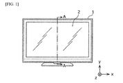
- FIG. 1 is a front view of a display device according to one or more embodiments of a first example of the present invention.
- Display device 1 is provided with a liquid crystal panel 2 that is an example of the display panel at the front surface.
- FIG. 2 is a diagram schematically illustrating a cross-section of a main part of the display device 1 cutting across the line A-A in FIG. 1 .
- a first backlight 10A and a second backlight 10B are disposed in a line in a sub-scanning direction (hereinafter, referred to as the y direction) of the liquid crystal panel 2.
- a direct type backlight is a backlight positioned behind the display panel, over the entire surface of the display panel.
- the first backlight 10A and the second backlight 10B are each provided with a substrate 11, a plurality of light emitting diodes (LED) 12, and a plurality of lenses 13 respectively.
- the plurality of LEDs 12 is disposed in a line in a main scanning direction (hereinafter, referred to as the x direction) of the liquid crystal panel 2 on the substrate 11.
- Each lens 13 corresponds to one of the plurality of LEDs 12 and is disposed on the corresponding LED 12.
- a circuit for supplying a power to each LED 12 from a power source is wired on the substrate 11.
- Each LED 12 emits a light towards the back surface of the liquid crystal panel 2.
- Each substrate 11 is connected to a driver 15.
- the driver 15 alternately lights the first backlight 10A and the second backlight 10B synchronous to a writing of an image to the display panel 2 so that while one of the first backlight 10A or the second backlight 10B is lit, the other one is unlit.
- the liquid crystal panel 2 may comprise a first area 16A provided in a position facing the first backlight 10A and a second area 16B provided in a position facing the second backlight 10B.
- the first area 16A and the second area 16B may not have an overlapping area.
- a coordinate in the y direction of the highest portion of the liquid crystal panel 2 is t, and a coordinate in the y direction of the lowest portion of the liquid crystal panel 2 is b.
- a coordinate of the mid-point in the y direction between a position of the LED 12 of the first backlight 10A and a position of the LED 12 of the second backlight 10B is m.
- the first area 16A is an area on the liquid crystal panel 2 that satisfies m ⁇ y ⁇ t
- the second area 16B is an area on the liquid crystal panel 2 that satisfies b ⁇ y ⁇ m.
- the disposed position in a z direction of the first backlight 10A is determined so that a light emitted from the first backlight 10A reaches not only the first area 16A, but also reaches the second area 16B. Further, the disposed position in the z direction of the second backlight 10B is determined so that a light emitted from the second backlight 10B reaches not only the second area 16B, but also reaches the first area 16A.
- the determination method of the disposed position in the z direction of the first backlight 10A is described with reference to FIG. 2 .
- a distance between a diffusion sheet 14 disposed on the back surface of the liquid crystal panel 2 and the z direction between each LED 12 is D.
- a length in the y direction of the liquid crystal panel 2 is H.
- the LED 12 and lens 13 are designed so that the peak intensity of the light emitted from the LED 12 does not come to the front, but comes in a direction inclined from the front (direction at angle ⁇ in FIG. 2 ). Because a distance to the liquid crystal panel 2 from the LED 12 differs according to the position of the liquid crystal panel 2, the intensity of the light hitting the surface of the liquid crystal panel 2 is uniform as possible.
- the peak direction ⁇ of the light intensity may have a constant width so as to satisfy the following equation 1. ⁇ 1 ⁇ ⁇ ⁇ ⁇ 2
- ⁇ 1 and ⁇ 2 indicate the minimum angle and the maximum angle in the peak direction of the light intensity of LED 12.
- the light irradiated by the first backlight 10A reaches both the first area 16A and the second area 16B.
- FIG. 4 is a diagram to describe a method for determining a disposed position in the z direction of the second backlight 10B.
- Other reference codes are the same as in FIG. 2 .
- Equation 2 The peak direction of light intensity of a light emitted from the LED 12 of the second backlight 10B also applies equation 2 in a similar manner to that of the first backlight 10A illustrated in FIG. 2 . Further, the equations 3 and 4 are also applied by using a diagram. As a result, equation 7 can be derived from the equations 2 to 4.
- the second backlight 10B at the position that satisfies the equation 7, the light irradiated by the second backlight 10B reaches both the first area 16A and the second area 16B.
- the first backlight 10A is disposed in the position where a first peak light, a rectilinear light in a direction where a light intensity of the light emitted from the first backlight 10A is at its peak, reaches the second area 16B.
- the first backlight 10A is disposed in a position where, within a range of emission directions that the first peak light can take, the first peak light that travels straight in a first direction (direction of the angle ⁇ 2 ) that is an emission direction nearest to an optical axis of the first backlight 10A, or the first peak light that travels straight in a second direction (direction of the angle ⁇ 1 ) that is an emission direction farthest from the optical axis of the first backlight 10A, reaches the second area16B.
- the second backlight 10B is disposed in a position where a second peak light, a rectilinear light in a direction where a light intensity of the light emitted from the second backlight 10B is at its peak, reaches the first area 16A.
- the second backlight 10B is disposed in a position where, within a range of emission directions that the second peak light can take, the second peak light that travels straight in a third direction (direction of the angle ⁇ 2 ) that is an emission direction nearest to an optical axis of the second backlight 10B, or the second peak light that travels straight in a fourth direction (direction of the angle ⁇ 1 ) that is an emission direction farthest from the optical axis of the second backlight 10B, reaches the first area16A.
- a light where each backlight irradiates can reach the first area 16A and the second area 16B by disposing the first backlight 10A and the second backlight 10B in the position in the z direction that satisfies the equation 7. That is, the light emitted from the first backlight 10A reaches not only the first area 16A but also reaches the second area 16B. Further, the light emitted from the second backlight 10B reaches not only the second area 16B but also reaches the first area 16A. Accordingly, a light of a frequency of twice the frequency of the intermittent operation of each backlight reaches each area. Therefore, flicker can be reduced.
- One or more embodiments of the display device according to the second example differ from one or more embodiments of the first example in that three backlights are provided.
- FIG. 5 is a diagram schematically illustrating a cross-section of a main part of the display device 1 cutting across the line A-A in FIG. 1 .
- the number of backlights is different from the display device 1 illustrated in FIG. 5 .
- a first backlight 10A, a second backlight 10B, and a third backlight 10C are disposed in a line in a y direction.
- the first backlight 10A, the second backlight 10B, and a third backlight 10C are disposed in a line at equal intervals.
- a configuration of each backlight may be the same as in one or more embodiments of the first example. Therefore, detailed descriptions are not repeated here.
- Each substrate 11 of each backlight is connected to a driver 15.
- the driver 15 alternately lights the first backlight 10A, the second backlight 10B, and the third backlight 10C synchronous to a writing of an image to the liquid crystal panel 2 so that while one of the first backlight 10A, the second backlight 10B, or the third backlight 10C is lit, other two are unlit.
- the liquid crystal panel 2 may comprise a first area 16A provided in a position facing the first backlight 10A, a second area 16B provided in a position facing the second backlight 10B, and a third area 16C provided in a position facing the third backlight 10C. None of the areas overlap with an adjacent area.
- a width in the y direction of each area is H/N.
- the disposed position in the z direction of the first backlight 10A is determined so that a light emitted from the first backlight 10A reaches not only the first area 16A, but also reaches the second area 16B. Further, a disposed position in the z direction of the second backlight 10B is determined so that a light emitted from the second backlight 10B reaches not only the second area 16B, but also reaches the first area 16A and the third area 16C. Furthermore, the disposed position of the third backlight 10C is determined so that a light emitted from the third backlight 10C reaches not only the third area 16C, but also reaches the second area 16B.
- the method for determining the disposed position in the z direction of the first backlight 10A may be as described with respect to the first example, and the first backlight 10A is disposed at the position that satisfies the equation 7.
- the disposed position in the z direction of the second backlight 10B when a light emitted from the second backlight 10B reaches the first area 16A and second area 16B may be as described with respect to the first example. That is, the second backlight 10B is disposed at the position that satisfies the equation 7.
- the disposed position in the z direction of the second backlight 10B when a light emitted from the second backlight 10B reaches the second area 16B and the third area 16C is calculated in the same manner as the disposed position in the z direction of the first backlight 10A. That is, the second backlight 10B is disposed at the position that satisfies the equation 7.
- the disposed position in the z direction of the third backlight 10C when a light emitted from the third backlight 10C reaches the second area 16B and the third area 16C is calculated in the same manner as the disposed position in the z direction of the second backlight 10B when a light emitted from the second backlight 10B reaches the first area 16a and the second area 16B. That is, the third backlight 10C is disposed at the position that satisfies the equation 7.
- the second backlight 10B is further disposed in the position where the second peak light that travels straight in a third direction (direction of the angle ⁇ 2 ), or the second peak light that travels straight in a fourth direction (direction of the angle ⁇ 1 ), reaches the third area 16C.
- the third backlight 10C is disposed in a position where a third peak light, a rectilinear light in a direction where a light intensity of the light emitted from the third backlight 10C is at its peak, reaches the second area 16B.
- the third backlight 10C is disposed in a position where, within a range of emission directions that the third peak light can take, the third peak light that travels straight in a fifth direction (direction of the angle ⁇ 2 ) that is an emission direction nearest to an optical axis of the third backlight 10C, or the third peak light that travels straight in a sixth direction (direction of the angle ⁇ 1 ) that is an emission direction farthest from the optical axis of the third backlight 10C, reaches the second area 16B.
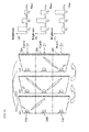
- FIG. 6 illustrates a diagram to describe an advantageous effect of the display device 1 according to one or more embodiments of the second example.
- the plurality of backlights are lit in order of the first backlight 10A, the second backlight 10B, and the third backlight 10C.
- the backlight 10A, second backlight 10B and third backlight 10C are lit respectively at successive times T1, T2, and T3.
- FIG. 6(d) is a graph illustrating a brightness of the light reaching the first area 16A, and the horizontal axis indicates time and the vertical axis indicates the brightness of the light.
- FIG. 6(e) is a graph illustrating a brightness of the light reaching the second area 16B, and the horizontal axis indicates time and the vertical axis indicates the brightness of the light.
- FIG. 6(f) is a graph illustrating a brightness of the light reaching the third area 16C, and the horizontal axis indicates time and the vertical axis indicates the brightness of the light.
- a light from the first backlight 10A slightly reaches even the third area 16C. This is because the disposed position of the first backlight 10A is determined so that the peak light of the first backlight 10A reaches the border between the second area 16B and the third area 16C. For the same reason, a light from the third backlight 10C slightly reaches the first area 16A.
- FIG. 7 is a diagram illustrating a change in brightness of the light when a light emitted from each backlight does not reach an adjacent area.
- the plurality of backlights are lit in order of the first backlight 10A, the second backlight 10B and the third backlight 10C.
- the backlight 10A, second backlight 10B, and third backlight 10C are lit respectively at successive times T1, T2, and T3.
- FIG. 7(d) is a graph illustrating a brightness of the light reaching the first area 16A, and the horizontal axis indicates time and the vertical axis indicates the brightness of the light.
- FIG. 7(e) is a graph illustrating a brightness of the light reaching the second area 16B, and the horizontal axis indicates time and the vertical axis indicates the brightness of the light.
- FIG. 7(f) is a graph illustrating a brightness of the light reaching the third area 16C, and the horizontal axis indicates time and the vertical axis indicates the brightness of the light.
- a light reaches the first area 16A only at the time T1, and a light does not reach there other than at that time.
- this is also the same in the second area 16B and the third area 16C.
- a light reaches not only at time T1 when the first backlight 10 A is lit, but reaches at the times T2 and T3 also.
- this is also the same in the second area 16B and the third area 16C. Accordingly, if each backlight is operated intermittently at 60 Hz, a light of 180 Hz which is three times larger reaches each area. Further, a change in brightness with respect to the time change is also smooth.
- FIG. 8 is a diagram illustrating an example of a display device where three backlights are disposed in a line at non-uniform spacing. As illustrated in FIG. 8 , a distance between the first backlight 10A and the second backlight 10B is L1, and a distance between the second backlight 10B and the third backlight 10C is L2. Such other conditions may be the same as in one or more embodiments of the second example.
- the light irradiated by the first backlight 10A reaches both the first area 16A and the second area 16B.
- the disposed position in the z direction of the second backlight 10B when a light irradiated from the second backlight 10B reaches both the first area 16A and the second area 16B can be calculated by the same calculation formula. Further, the disposed position in the z direction of the second backlight 10B when a light irradiated from the second backlight 10B reaches both the second area 16B and the third area 16C can be calculated by the same calculation formula. Furthermore, the disposed position in the z direction of the third backlight 10B when a light irradiated from the third backlight 10B reaches both the second area 16B and the third area 16C can be calculated by the same calculation formula.
- ⁇ 1 may be set to 10° and ⁇ 2 may be set to 20° to satisfy the below table.
- a width W in the y direction of each area may be H/N
- D (min) may be Htan ⁇ 1 /2N
- D (max) may be 3Htan ⁇ 2 /2N.
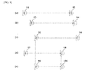
- FIG. 9 is a diagram schematically illustrating an example of the calculated disposed position in the z direction of each backlight.
- FIG. 9(a) is a diagram illustrating one example of a disposed position in the z direction of the first backlight 10A when a light irradiated from the first backlight 10A reaches both the first area 16A and the second area 16B.
- the first backlight 10A is disposed, for example, between position 91 and position 92.
- FIG. 9(b) is a diagram illustrating one example of a disposed position in the z direction of the second backlight 10B when a light irradiated from the second backlight 10B reaches both the first area 16A and the second area 16B.
- the second backlight 10B is disposed, for example, between position 93 and position 94.
- FIG. 9(c) is a diagram illustrating one example of a disposed position in the z direction of the second backlight 10B when a light irradiated from the second backlight 10B reaches both the second area 16B and the third area 16C.
- the second backlight 10B is disposed, for example, between position 95 and position 96.
- FIG. 9(d) is a diagram illustrating one example of a disposed position in the z direction of the third backlight 10C when a light irradiated from the third backlight 10C reaches both the second area 16B and the third area 16C.
- the third backlight 10C is disposed, for example, between position 97 and position 98.
- each backlight When the disposed positions of each backlight are different from each other, as illustrated in FIGS. 9(a) to 9(d) , all the backlights are disposed in positions that satisfy all the conditions of FIGS. 9(a) to 9(d) as illustrated in FIG. 9(e) .
- all the backlights of positions 91, 93, 95, and 97 on the side nearest to the liquid crystal panel 2, and those of positions 92, 94, 96, and 98 on the side farthest from the liquid crystal panel 2 may be positioned between positions 99 and 100. By this, all of the positions in the z direction of the backlights can be aligned.
- the plurality of LEDs 12 arrayed in each backlight is arrayed in a row in the x direction, but number of rows is not necessarily limited to one.
- FIG. 10 is a diagram schematically illustrating the inside of the display device 1.
- the display device 1 may comprise the first backlight 10A and the second backlight 10B arrayed in the y direction.
- the first backlight 10A may comprise a first LED group 40A and a second LED group 40B arrayed in the y direction.
- Each of the first LED group 40A and the second LED group 40B may comprise at least one LED arrayed in the x direction.
- the first LED group 40A may comprise LEDs 41 to 45 arrayed in the x direction
- the second LED group 40B may comprise LEDs 46 to 50 arrayed in the x direction.
- the first backlight 10A is disposed in a position in the z direction where light emitted from the first LED reaches the first area 16A and the second area 16B when the first LED is assumed to be disposed in an intermediate position (position of a sub-line 60A) in the y direction of the first LED group 40A and the second LED group 40B included in the first backlight 10B.
- An intermediate position may be a position that is half the distance in the y direction between the first LED group 40A and the second LED group 40B, or it may be a position other than that.
- the second backlight 10B is configured identically to the first backlight 10A.
- the second backlight 10B is disposed in a position in the z direction where light emitted from the second LED reaches the first area 16A and the second area 16B when the second LED is assumed to be disposed in an intermediate position (position of a sub-line 60B) in the y direction of the first LED group 40A and the second LED group 40B included in the second backlight 10B.
- the third backlight 10C may be configured identically to the first backlight 10A (or the second backlight 10B) illustrated in FIG. 10 .
- a position in the z direction for the third backlight 10C can be calculated in the same manner as that for the first backlight 10A.
- the number of backlights may be four or more.
- One or more embodiments of the present invention can apply to a liquid crystal display device and the like provided with a liquid crystal panel.
Landscapes
- Physics & Mathematics (AREA)
- Nonlinear Science (AREA)
- General Physics & Mathematics (AREA)
- Engineering & Computer Science (AREA)
- Chemical & Material Sciences (AREA)
- Mathematical Physics (AREA)
- Crystallography & Structural Chemistry (AREA)
- Optics & Photonics (AREA)
- Theoretical Computer Science (AREA)
- Computer Hardware Design (AREA)
- Planar Illumination Modules (AREA)
- Liquid Crystal Display Device Control (AREA)
- Control Of Indicators Other Than Cathode Ray Tubes (AREA)
- Liquid Crystal (AREA)
Abstract
Description
- The present invention relates to a display device, and particularly relates to a display device provided with a backlight that irradiates a light to a backplane of a display panel.
- Conventionally, a liquid crystal display device is known that intermittently lights a plurality of backlights while switching and while synchronizing to a writing of an image to a liquid crystal panel (see Patent Document 1).
- Intermittently lighting a plurality of backlights in this manner prevents so-called motion image blurring, i.e., the image of the previous frame remaining as an after image.
- [Patent Document 1] Japanese Unexamined Patent Application No.
2002-231034 - However, with this conventional liquid crystal display device, flicker stands out when intermittently lighting a plurality of backlights and controlling the illuminating light of each backlight with low frequency phasing, for example 60 Hz, according to the frame rate.
- One or more embodiments of the present invention provide a display device that can reduce flicker.
- In one or more embodiments of the present invention, a display device may comprise: a display panel; a direct-type first backlight and a direct-type second backlight that each intermittently irradiate light toward a back surface of the display panel and is disposed adjacently in a sub-scanning direction of the display panel, wherein a display area of the display panel may comprise a first area provided in a position facing the direct-type first backlight and a second area provided in a position facing the direct-type second backlight, the direct-type first backlight may be disposed in a position where the light emitted from the direct-type first backlight reaches the first area and the second area, and the direct-type second backlight may be disposed in a position where the light emitted from the direct-type second backlight reaches the first area and the second area.
- In one or more embodiments of this configuration, for example, the light emitted from the direct-type first backlight reaches not only the first area but also the second area. Furthermore, the light emitted from the direct-type second backlight may reach not only the second area but also the first area. Therefore, light having twice the frequency of the frequency of the intermittent operation of each backlight may reach each area. Therefore, flicker can be reduced.
- In one or more embodiments of the present invention, the direct-type first backlight may be disposed in a position where a first peak light reaches the second area, the first peak light being a rectilinear light in a direction where light intensity of the light emitted from the direct-type first backlight is at a peak; and the direct-type second backlight may be disposed in a position where a second peak light reaches the first area, the second peak light being a rectilinear light in a direction where light intensity of the light emitted from the direct-type second backlight is at a peak.
- In one or more embodiments of the present invention, each backlight may be designed so that the peak of the emitted light is emitted in an offset direction from the optical axis direction. Therefore, for example, disposing the direct-type first backlight in a position where the first peak light reaches the second area may allow the emitted light of the direct-type first backlight to be guided to the first area and the second area. Also disposing the direct-type second backlight in a similar manner may allow the emitted light of the direct-type second backlight to be guided to the first area and to the second area.
- In one or more embodiments of the present invention, the direct-type first backlight may be disposed in a position where, within a range of emission directions of the first peak light, the first peak light reaches the second area by traveling straight in a first direction that is an emission direction nearest to an optical axis of the direct-type first backlight or traveling straight in a second direction that is an emission direction farthest from the optical axis of the direct-type first backlight; and the direct-type second backlight may be disposed in a position where, within a range of emission directions of the second peak light, the second peak light reaches the first area by traveling straight in a third direction that is an emission direction nearest to an optical axis of the direct-type second backlight or traveling straight in a fourth direction that is an emission direction farthest from the optical axis of the direct-type second backlight.
- In one or more embodiments of the present invention, the emission direction of the peak light emitted from the backlight may have a constant width. Therefore, disposing the direct-type first backlight and the direct-type second backlight in the above position may allow each of the emitted lights of the direct-type first backlight and the direct-type second backlight to be guided to the first area and to the second area.
- In one or more embodiments of the present invention, the direct-type first backlight may be disposed in a position between a position of the direct-type first backlight when the first peak light that travels straight in the first direction reaches an end portion of the second area farthest away from the first area and a position of the direct-type first backlight when the first peak light that travels straight in the second direction reaches a border between the first area and the second area.
- In one or more embodiments of the present invention, disposing the direct-type first backlight in this type of position may allow the emitted light of the direct-type first backlight to be guided to the first area and to the second area.
- Further, the direct-type second backlight may be disposed in a position between a position of the direct-type second backlight when the second peak light that travels straight in the third direction reaches an end portion of the first area farthest away from the second area and a position of the direct-type second backlight when the second peak light that travels straight in the fourth direction reaches a border between the first area and the second area.
- In one or more embodiments of the present invention, disposing the direct-type second backlight in this type of position may allow the emitted light of the direct-type second backlight to be guided to the first area and to the second area.
- Furthermore, the above display device may further comprise a driver that alternately lights the direct-type first backlight and the direct-type second backlight synchronously with a writing of an image on the display panel so that one of the direct-type first backlight or the direct-type second backlight is lit while the other is unlit.
- Accordingly, in one or more embodiments of the present invention, synchronizing with writing of an image to the display panel may allow the direct-type first backlight and the direct-type second backlight to be intermittently lit.
- Further, in one or more embodiments of the present invention, each of the direct-type first backlight and the direct-type second backlight may comprise a first LED group and a second LED group arrayed in the sub-scanning direction of the display panel, each of the first LED group and the second LED group may comprise an LED arrayed in a main scanning direction of the display panel, the direct-type first backlight may be disposed in a position where, in the sub-scanning direction of the display panel, light emitted from the first LED reaches the first area and the second area when the first LED is disposed in an intermediate position of the first LED group and the second LED group in the direct-type first backlight, and the direct-type second backlight may be disposed in a position where, in the sub-scanning direction of the display panel, light emitted from the second LED reaches the first area and the second area when the second LED is disposed in an intermediate position of the first LED group and the second LED group in the direct-type second backlight.
- Accordingly, in one or more embodiments of the present invention, a disposed position for each backlight can be determined even if a position in the sub-scanning direction between LEDs is not aligned.
- Further, the display device described above may further comprise a direct-type third backlight that intermittently emits light toward the back surface of the display panel, wherein the direct-type first backlight, direct-type second backlight, and third backlight may be disposed adjacently in the sub-scanning direction of the display panel in an order of the direct-type first backlight, the direct-type second backlight, and the third backlight, a display area of the display panel may further comprise a third area provided in a position facing the third backlight, the direct-type second backlight may be disposed in a position where the light emitted from the direct-type second backlight reaches the first area, the second area, and the third area, and the third backlight may be disposed in a position where the light emitted from the third backlight reaches the second area and the third area.
- In one or more embodiments of this configuration, for example, the light emitted from the direct-type second backlight may reach not only the second area but also the first area, and the third area. Furthermore, the light emitted from the third backlight may reach not only the third area but also the second area. Light having three times the frequency of the frequency of the intermittent operation of each backlight may reach each area. Therefore, flicker can be reduced.
- Further, the direct-type second backlight may be disposed in a position where the second peak light reaches the third area, and the third backlight may be disposed in a position where a third peak light reaches the second area, the third peak light being a rectilinear light in a direction where light intensity of the light emitted from the third backlight is at a peak.
- In one or more embodiments of the present invention, each backlight may be designed so that the peak of the emitted light is emitted in an offset direction from the optical axis direction. Therefore, disposing the direct-type second backlight in a position where the second peak light reaches the third area may allow the emitted light of the direct-type second backlight to be guided to the second area and to the third area. Further, disposing the third backlight in a position where the third peak light reaches the second area may allow the emitted light of the third backlight to be guided to the second area and to the third area.
- In one or more embodiments of the present invention, the direct-type second backlight may be disposed in a position where the second peak light reaches the third area by traveling straight in the third direction or traveling straight in the fourth direction, and the third backlight may be disposed in a position where, within a range of emission directions of the third peak light, the third peak light reaches the second area by traveling straight in a fifth direction that is an emission direction nearest to an optical axis of the third backlight or traveling straight in a sixth direction that is an emission direction farthest from the optical axis of the third backlight.
- In one or more embodiments of the present invention, the emission direction of the peak light emitted from the backlight may have a constant width. Therefore, disposing the direct-type second backlight and the third backlight in the above position may allow each of the emitted lights of the direct-type second backlight and the third backlight to be guided to the second area and to the third area.
- In one or more embodiments of the present invention, the direct-type second backlight may be disposed in a position between a position of the direct-type second backlight when the second peak light that travels straight in the third direction reaches an end portion of the third area farthest away from the second area and a position of the direct-type second backlight when the second peak light that travels straight in the fourth direction reaches a border between the second area and the third area.
- In one or more embodiments of the present invention, disposing the direct-type second backlight in this type of position may allow the emitted light of the direct-type second backlight to be guided to the second area and to the third area.
- In one or more embodiments of the present invention, the third backlight may be disposed in a position between a position of the third backlight when the third peak light that travels straight in the fifth direction reaches an end portion of the second area farthest away from the third area and a position of the third backlight when the third peak light that travels straight in the sixth direction reaches a border between the second area and the third area.
- In one or more embodiments of the present invention, disposing the third backlight in this type of position may allow the emitted light of the third backlight to be guided to the second area and to the third area.
- In one or more embodiments of the present invention, the display device described above may further comprise a driver that alternately lights the direct-type first backlight, the direct-type second backlight, and the third backlight synchronously with a writing of an image on the display panel so that while one of the direct-type first backlight, the direct-type second backlight, or the third backlight is lit, the other two are unlit.
- Accordingly, in one or more embodiments of the present invention, synchronizing with writing of an image to the display panel allows the direct-type first backlight, the direct-type second backlight, and the third backlight to be intermittently lit.
- One or more embodiments of the present invention can provide a display device that reduces flicker.
-
-
FIG. 1 is a front view of a display device according to one or more embodiments of a first example of the present invention. -
FIG. 2 is a diagram schematically illustrating a cross-section of a main part of the display device cutting across the line A-A inFIG. 1 according to one or more embodiments of the present invention. -
FIG. 3 is a diagram to describe a position of afirst backlight 10A that satisfies equation 7 according to one or more embodiments of the present invention. -
FIG. 4 is a diagram to describe a method for determining a disposed position in the z direction of a direct-typesecond backlight 10B according to one or more embodiments of the present invention. -
FIG. 5 is a diagram schematically illustrating a cross-section of a main part of the display device cutting across the line A-A inFIG. 1 according to one or more embodiments of the present invention. -
FIG. 6 is a diagram to describe an advantageous effect of the display device according to one or more embodiments of a second example of the present invention. -
FIG. 7 is a diagram illustrating a change in brightness of the light when a light emitted from each backlight does not reach an adjacent area according to one or more embodiments of the present invention. -
FIG. 8 is a diagram illustrating an example of a display device where three backlights are disposed in a line at non-uniform spacing according to one or more embodiments of the present invention. -
FIG. 9 is a diagram schematically illustrating an example of the disposed position in the z direction of each backlight according to one or more embodiments of the present invention. -
FIG. 10 is a diagram to describe the disposed position of the LEDs comprised in a backlight according to one or more embodiments of a second modified example of the present invention. - Embodiments of the present invention are described in detail below with reference to the drawings. The embodiments described below illustrate examples of the present invention. Numerical values, shapes, configuration elements, disposed positions, connection modes, and the like illustrated in the embodiments below are mere examples, and are not intended to limit the present invention. The present invention is specified by the scope of the claims.
-
FIG. 1 is a front view of a display device according to one or more embodiments of a first example of the present invention.Display device 1 is provided with aliquid crystal panel 2 that is an example of the display panel at the front surface. -
FIG. 2 is a diagram schematically illustrating a cross-section of a main part of thedisplay device 1 cutting across the line A-A inFIG. 1 . - On the backplane side of the inside of the
display device 1, afirst backlight 10A and asecond backlight 10B, each a direct type, are disposed in a line in a sub-scanning direction (hereinafter, referred to as the y direction) of theliquid crystal panel 2. A direct type backlight is a backlight positioned behind the display panel, over the entire surface of the display panel. Thefirst backlight 10A and thesecond backlight 10B are each provided with asubstrate 11, a plurality of light emitting diodes (LED) 12, and a plurality oflenses 13 respectively. The plurality ofLEDs 12 is disposed in a line in a main scanning direction (hereinafter, referred to as the x direction) of theliquid crystal panel 2 on thesubstrate 11. Eachlens 13 corresponds to one of the plurality ofLEDs 12 and is disposed on the correspondingLED 12. - A circuit for supplying a power to each
LED 12 from a power source is wired on thesubstrate 11. EachLED 12 emits a light towards the back surface of theliquid crystal panel 2. Eachsubstrate 11 is connected to adriver 15. Thedriver 15 alternately lights thefirst backlight 10A and thesecond backlight 10B synchronous to a writing of an image to thedisplay panel 2 so that while one of thefirst backlight 10A or thesecond backlight 10B is lit, the other one is unlit. - The
liquid crystal panel 2 may comprise afirst area 16A provided in a position facing thefirst backlight 10A and asecond area 16B provided in a position facing thesecond backlight 10B. Thefirst area 16A and thesecond area 16B may not have an overlapping area. A coordinate in the y direction of the highest portion of theliquid crystal panel 2 is t, and a coordinate in the y direction of the lowest portion of theliquid crystal panel 2 is b. Further, a coordinate of the mid-point in the y direction between a position of theLED 12 of thefirst backlight 10A and a position of theLED 12 of thesecond backlight 10B is m. At that time, thefirst area 16A is an area on theliquid crystal panel 2 that satisfies m ≤ y ≤ t, and thesecond area 16B is an area on theliquid crystal panel 2 that satisfies b ≤ y < m. - In one or more embodiments, the disposed position in a z direction of the
first backlight 10A is determined so that a light emitted from thefirst backlight 10A reaches not only thefirst area 16A, but also reaches thesecond area 16B. Further, the disposed position in the z direction of thesecond backlight 10B is determined so that a light emitted from thesecond backlight 10B reaches not only thesecond area 16B, but also reaches thefirst area 16A. - A method for determining the disposed position in the z direction of each backlight is described below.
- The determination method of the disposed position in the z direction of the
first backlight 10A is described with reference toFIG. 2 . First, a distance between adiffusion sheet 14 disposed on the back surface of theliquid crystal panel 2 and the z direction between eachLED 12 is D. Further, a length in the y direction of theliquid crystal panel 2 is H. Furthermore, a number of backlights is N (in case ofFIG. 2 , N = 2). TheLED 12 of thefirst backlight 10A is disposed in the position at y = m + (H/2N). - The
LED 12 andlens 13 are designed so that the peak intensity of the light emitted from theLED 12 does not come to the front, but comes in a direction inclined from the front (direction at angle θ inFIG. 2 ). Because a distance to theliquid crystal panel 2 from theLED 12 differs according to the position of theliquid crystal panel 2, the intensity of the light hitting the surface of theliquid crystal panel 2 is uniform as possible. The peak direction θ of the light intensity may have a constant width so as to satisfy thefollowing equation 1.
- Here, θ1 and θ2 indicate the minimum angle and the maximum angle in the peak direction of the light intensity of
LED 12. - Modifying
equation 1 leads toequation 2.
- Here, 0 < θ < π/2.
- Meanwhile, the following
equations 

- When
equations equation 2, the equation 5 is obtained.
- When equation 5 is modified, an equation 6 is obtained.

- Because the relationship of
equation 2 applies, even when tanθ of the extreme left side in equation 6 is substituted by tanθ1, and tanθ of the extreme right side in equation 6 is substituted by tanθ2, the relationship of inequality is maintained. In other words, the flowing equation 7 is derived.
- By disposing the
first backlight 10A at the position that satisfies equation 7, the light irradiated by thefirst backlight 10A reaches both thefirst area 16A and thesecond area 16B. -
FIG. 3 is a diagram to describe a position of thefirst backlight 10A that satisfies the equation 7. That is, the position of thefirst backlight 10A that satisfies D = Htanθ1/2N is theposition 31, and the position of thefirst backlight 10A that satisfies D = 3Htanθ2/2N is theposition 32. In other words, thefirst backlight 10A may be disposed betweenposition 31 andposition 32. -
FIG. 4 is a diagram to describe a method for determining a disposed position in the z direction of thesecond backlight 10B. TheLED 12 of thesecond backlight 10B is disposed in the position at y = m - (H/2N). Other reference codes are the same as inFIG. 2 . - The peak direction of light intensity of a light emitted from the
LED 12 of thesecond backlight 10B also appliesequation 2 in a similar manner to that of thefirst backlight 10A illustrated inFIG. 2 . Further, theequations equations 2 to 4. - That is, by disposing the
second backlight 10B at the position that satisfies the equation 7, the light irradiated by thesecond backlight 10B reaches both thefirst area 16A and thesecond area 16B. - In summary, in one or more embodiments, the
first backlight 10A is disposed in the position where a first peak light, a rectilinear light in a direction where a light intensity of the light emitted from thefirst backlight 10A is at its peak, reaches thesecond area 16B. That is, thefirst backlight 10A is disposed in a position where, within a range of emission directions that the first peak light can take, the first peak light that travels straight in a first direction (direction of the angle θ2) that is an emission direction nearest to an optical axis of thefirst backlight 10A, or the first peak light that travels straight in a second direction (direction of the angle θ1) that is an emission direction farthest from the optical axis of thefirst backlight 10A, reaches the second area16B. Specifically, thefirst backlight 10A is disposed in a position between a disposed position of thefirst backlight 10A when the first peak light that travels straight in the first direction reaches an end portion (position at y = b) of thesecond area 16B farthest away from thefirst area 16A and a disposed position of thefirst backlight 10A when the first peak light that travels straight in the second direction reaches a border (position at y = m) between thefirst area 16A and thesecond area 16B. - Further, the
second backlight 10B is disposed in a position where a second peak light, a rectilinear light in a direction where a light intensity of the light emitted from thesecond backlight 10B is at its peak, reaches thefirst area 16A. That is, thesecond backlight 10B is disposed in a position where, within a range of emission directions that the second peak light can take, the second peak light that travels straight in a third direction (direction of the angle θ2) that is an emission direction nearest to an optical axis of thesecond backlight 10B, or the second peak light that travels straight in a fourth direction (direction of the angle θ1) that is an emission direction farthest from the optical axis of thesecond backlight 10B, reaches the first area16A. Specifically, thesecond backlight 10B is disposed in a position between a disposed position of thesecond backlight 10B when the second peak light that travels straight in the third direction reaches an end portion (position at y = t) of thefirst area 16A farthest away from thesecond area 16B and a disposed position of thesecond backlight 10B when the second peak light that travels straight in the fourth direction reaches a border (position at y = m) between thefirst area 16A and thesecond area 16B. - As described above, in the
display device 1 according to one or more embodiments of the first example, a light where each backlight irradiates can reach thefirst area 16A and thesecond area 16B by disposing thefirst backlight 10A and thesecond backlight 10B in the position in the z direction that satisfies the equation 7. That is, the light emitted from thefirst backlight 10A reaches not only thefirst area 16A but also reaches thesecond area 16B. Further, the light emitted from thesecond backlight 10B reaches not only thesecond area 16B but also reaches thefirst area 16A. Accordingly, a light of a frequency of twice the frequency of the intermittent operation of each backlight reaches each area. Therefore, flicker can be reduced. - Next, a display device according to one or more embodiments of a second example of the present invention is described. One or more embodiments of the display device according to the second example differ from one or more embodiments of the first example in that three backlights are provided.
- An outer appearance of the display device is as illustrated in
FIG. 1 .FIG. 5 is a diagram schematically illustrating a cross-section of a main part of thedisplay device 1 cutting across the line A-A inFIG. 1 . - The number of backlights is different from the
display device 1 illustrated inFIG. 5 . - On the backplane side of the inside of the
display device 1, afirst backlight 10A, asecond backlight 10B, and athird backlight 10C are disposed in a line in a y direction. Thefirst backlight 10A, thesecond backlight 10B, and athird backlight 10C are disposed in a line at equal intervals. A configuration of each backlight may be the same as in one or more embodiments of the first example. Therefore, detailed descriptions are not repeated here. - Each
substrate 11 of each backlight is connected to adriver 15. Thedriver 15 alternately lights thefirst backlight 10A, thesecond backlight 10B, and thethird backlight 10C synchronous to a writing of an image to theliquid crystal panel 2 so that while one of thefirst backlight 10A, thesecond backlight 10B, or thethird backlight 10C is lit, other two are unlit. - The
liquid crystal panel 2 may comprise afirst area 16A provided in a position facing thefirst backlight 10A, asecond area 16B provided in a position facing thesecond backlight 10B, and athird area 16C provided in a position facing thethird backlight 10C. None of the areas overlap with an adjacent area. A width in the y direction of each area is H/N. - In one or more embodiments, the disposed position in the z direction of the
first backlight 10A is determined so that a light emitted from thefirst backlight 10A reaches not only thefirst area 16A, but also reaches thesecond area 16B. Further, a disposed position in the z direction of thesecond backlight 10B is determined so that a light emitted from thesecond backlight 10B reaches not only thesecond area 16B, but also reaches thefirst area 16A and thethird area 16C. Furthermore, the disposed position of thethird backlight 10C is determined so that a light emitted from thethird backlight 10C reaches not only thethird area 16C, but also reaches thesecond area 16B. - A method for determining the disposed position in the z direction of each backlight is described below.
- The method for determining the disposed position in the z direction of the
first backlight 10A may be as described with respect to the first example, and thefirst backlight 10A is disposed at the position that satisfies the equation 7. - Further, the disposed position in the z direction of the
second backlight 10B when a light emitted from thesecond backlight 10B reaches thefirst area 16A andsecond area 16B may be as described with respect to the first example. That is, thesecond backlight 10B is disposed at the position that satisfies the equation 7. - The disposed position in the z direction of the
second backlight 10B when a light emitted from thesecond backlight 10B reaches thesecond area 16B and thethird area 16C is calculated in the same manner as the disposed position in the z direction of thefirst backlight 10A. That is, thesecond backlight 10B is disposed at the position that satisfies the equation 7. - The disposed position in the z direction of the
third backlight 10C when a light emitted from thethird backlight 10C reaches thesecond area 16B and thethird area 16C is calculated in the same manner as the disposed position in the z direction of thesecond backlight 10B when a light emitted from thesecond backlight 10B reaches the first area 16a and thesecond area 16B. That is, thethird backlight 10C is disposed at the position that satisfies the equation 7. - In summary regarding how the disposed positions of the
second backlight 10B and thethird backlight 10C may differ from one or more embodiments of the first example, thesecond backlight 10B is further disposed in the position where the second peak light that travels straight in a third direction (direction of the angle θ2), or the second peak light that travels straight in a fourth direction (direction of the angle θ1), reaches thethird area 16C. Specifically, thesecond backlight 10B is disposed in a position between a disposed position of thesecond backlight 10B when the second peak light that travels straight in the third direction reaches an end portion (position at y = b) of thethird area 16C farthest away from thesecond area 16B and a disposed position of thesecond backlight 10B when the second peak light that travels straight in the fourth direction reaches a border (position at y = b + (H/N)) between thesecond area 16B and thethird area 16C. - Further, the
third backlight 10C is disposed in a position where a third peak light, a rectilinear light in a direction where a light intensity of the light emitted from thethird backlight 10C is at its peak, reaches thesecond area 16B. That is, thethird backlight 10C is disposed in a position where, within a range of emission directions that the third peak light can take, the third peak light that travels straight in a fifth direction (direction of the angle θ2) that is an emission direction nearest to an optical axis of thethird backlight 10C, or the third peak light that travels straight in a sixth direction (direction of the angle θ1) that is an emission direction farthest from the optical axis of thethird backlight 10C, reaches thesecond area 16B. Specifically, thethird backlight 10C is disposed in a position between a disposed position of thethird backlight 10C when the third peak light that travels straight in the fifth direction reaches an end portion (position at y = t - (H/N)) of thesecond area 16B farthest away from thethird area 16C and a disposed position of thethird backlight 10C when the third peak light that travels straight in the sixth direction reaches a border (position at y = b + (H/N)) between thesecond area 16B and thethird area 16C. -
FIG. 6 illustrates a diagram to describe an advantageous effect of thedisplay device 1 according to one or more embodiments of the second example. As illustrated inFIGS. 6(a), 6(b) and 6(c) , the plurality of backlights are lit in order of thefirst backlight 10A, thesecond backlight 10B, and thethird backlight 10C. For example, thebacklight 10A,second backlight 10B andthird backlight 10C are lit respectively at successive times T1, T2, and T3.FIG. 6(d) is a graph illustrating a brightness of the light reaching thefirst area 16A, and the horizontal axis indicates time and the vertical axis indicates the brightness of the light.FIG. 6(e) is a graph illustrating a brightness of the light reaching thesecond area 16B, and the horizontal axis indicates time and the vertical axis indicates the brightness of the light.FIG. 6(f) is a graph illustrating a brightness of the light reaching thethird area 16C, and the horizontal axis indicates time and the vertical axis indicates the brightness of the light. A light from thefirst backlight 10A slightly reaches even thethird area 16C. This is because the disposed position of thefirst backlight 10A is determined so that the peak light of thefirst backlight 10A reaches the border between thesecond area 16B and thethird area 16C. For the same reason, a light from thethird backlight 10C slightly reaches thefirst area 16A. -
FIG. 7 is a diagram illustrating a change in brightness of the light when a light emitted from each backlight does not reach an adjacent area. As illustrated inFIGS. 7(a), 7(b) and 7(c) , the plurality of backlights are lit in order of thefirst backlight 10A, thesecond backlight 10B and thethird backlight 10C. For example, thebacklight 10A,second backlight 10B, andthird backlight 10C are lit respectively at successive times T1, T2, and T3.FIG. 7(d) is a graph illustrating a brightness of the light reaching thefirst area 16A, and the horizontal axis indicates time and the vertical axis indicates the brightness of the light.FIG. 7(e) is a graph illustrating a brightness of the light reaching thesecond area 16B, and the horizontal axis indicates time and the vertical axis indicates the brightness of the light.FIG. 7(f) is a graph illustrating a brightness of the light reaching thethird area 16C, and the horizontal axis indicates time and the vertical axis indicates the brightness of the light. As can been seen from the graph inFIG. 7(d) , a light reaches thefirst area 16A only at the time T1, and a light does not reach there other than at that time. As can been seen from graphs inFIGS. 7(e) and 7(f) , this is also the same in thesecond area 16B and thethird area 16C. - On the contrary, according to the
display device 1 according to one or more embodiments of the second example, as can been seen from the graph inFIG. 6(d) , a light reaches not only at time T1 when thefirst backlight 10 A is lit, but reaches at the times T2 and T3 also. As can been seen from graphs inFIGS. 6(e) and 6(f) , this is also the same in thesecond area 16B and thethird area 16C. Accordingly, if each backlight is operated intermittently at 60 Hz, a light of 180 Hz which is three times larger reaches each area. Further, a change in brightness with respect to the time change is also smooth. - In one or more embodiments of the second example, a description is given of three backlights disposed in a line with equal spacing, but the spacing of the backlights may not have to be equal.
-
FIG. 8 is a diagram illustrating an example of a display device where three backlights are disposed in a line at non-uniform spacing. As illustrated inFIG. 8 , a distance between thefirst backlight 10A and thesecond backlight 10B is L1, and a distance between thesecond backlight 10B and thethird backlight 10C is L2. Such other conditions may be the same as in one or more embodiments of the second example. - The
equations 8 and 9 are applied by using a diagram.

- When
equations 8 and 9 are substituted intoequation 2, the equation 10 is obtained.
- When equation 10 is modified, an
equation 11 is obtained.
- Because the relationship of
equation 2 applies, even when tanθ of the extreme left side inequation 11 is substituted by tanθ1, and tanθ of the extreme right side inequation 11 is substituted by tanθ2, the relationship of inequality is maintained. In other words, the flowingequation 12 is derived.
- By disposing the
first backlight 10A at the position that satisfiesequation 12, the light irradiated by thefirst backlight 10A reaches both thefirst area 16A and thesecond area 16B. - The disposed position in the z direction of the
second backlight 10B when a light irradiated from thesecond backlight 10B reaches both thefirst area 16A and thesecond area 16B can be calculated by the same calculation formula. Further, the disposed position in the z direction of thesecond backlight 10B when a light irradiated from thesecond backlight 10B reaches both thesecond area 16B and thethird area 16C can be calculated by the same calculation formula. Furthermore, the disposed position in the z direction of thethird backlight 10B when a light irradiated from thethird backlight 10B reaches both thesecond area 16B and thethird area 16C can be calculated by the same calculation formula. - For example, if a length H of the
liquid crystal panel 2 is 485.65mm and a number of backlights N is 3, then θ1 may be set to 10° and θ2 may be set to 20° to satisfy the below table.H 485.65mm 572.82mm 622.63 mm N 3 3 3 w 161.88mm 190.94mm 207.54mm θ1(min) 10° 10° 10° tanθ1 0.17632698 0.17632698 0.17632698 D (min) 14.27mm 16.83mm 18.30mm θ2 (max) 20° 20° 20° tanθ2 0.36397023 0.36397023 0.36397023 D (max) 88.38mm 104.24mm 113.31mm - As discussed above, a width W in the y direction of each area may be H/N, D (min) may be Htanθ1/2N, and D (max) may be 3Htanθ2/2N.
-
FIG. 9 is a diagram schematically illustrating an example of the calculated disposed position in the z direction of each backlight. -
FIG. 9(a) is a diagram illustrating one example of a disposed position in the z direction of thefirst backlight 10A when a light irradiated from thefirst backlight 10A reaches both thefirst area 16A and thesecond area 16B. Thefirst backlight 10A is disposed, for example, betweenposition 91 andposition 92. -
FIG. 9(b) is a diagram illustrating one example of a disposed position in the z direction of thesecond backlight 10B when a light irradiated from thesecond backlight 10B reaches both thefirst area 16A and thesecond area 16B. Thesecond backlight 10B is disposed, for example, betweenposition 93 andposition 94. -
FIG. 9(c) is a diagram illustrating one example of a disposed position in the z direction of thesecond backlight 10B when a light irradiated from thesecond backlight 10B reaches both thesecond area 16B and thethird area 16C. Thesecond backlight 10B is disposed, for example, betweenposition 95 andposition 96. -
FIG. 9(d) is a diagram illustrating one example of a disposed position in the z direction of thethird backlight 10C when a light irradiated from thethird backlight 10C reaches both thesecond area 16B and thethird area 16C. Thethird backlight 10C is disposed, for example, betweenposition 97 andposition 98. - When the disposed positions of each backlight are different from each other, as illustrated in
FIGS. 9(a) to 9(d) , all the backlights are disposed in positions that satisfy all the conditions ofFIGS. 9(a) to 9(d) as illustrated inFIG. 9(e) . In other words, all the backlights ofpositions liquid crystal panel 2, and those ofpositions liquid crystal panel 2, may be positioned betweenpositions - In one or more embodiments of the first example, the plurality of
LEDs 12 arrayed in each backlight is arrayed in a row in the x direction, but number of rows is not necessarily limited to one. -
FIG. 10 is a diagram schematically illustrating the inside of thedisplay device 1. Thedisplay device 1 may comprise thefirst backlight 10A and thesecond backlight 10B arrayed in the y direction. - The
first backlight 10A may comprise afirst LED group 40A and asecond LED group 40B arrayed in the y direction. - Each of the
first LED group 40A and thesecond LED group 40B may comprise at least one LED arrayed in the x direction. For example, thefirst LED group 40A may compriseLEDs 41 to 45 arrayed in the x direction, and thesecond LED group 40B may compriseLEDs 46 to 50 arrayed in the x direction. - The
first backlight 10A is disposed in a position in the z direction where light emitted from the first LED reaches thefirst area 16A and thesecond area 16B when the first LED is assumed to be disposed in an intermediate position (position of a sub-line 60A) in the y direction of thefirst LED group 40A and thesecond LED group 40B included in thefirst backlight 10B. An intermediate position may be a position that is half the distance in the y direction between thefirst LED group 40A and thesecond LED group 40B, or it may be a position other than that. - The
second backlight 10B is configured identically to thefirst backlight 10A. In other words, thesecond backlight 10B is disposed in a position in the z direction where light emitted from the second LED reaches thefirst area 16A and thesecond area 16B when the second LED is assumed to be disposed in an intermediate position (position of a sub-line 60B) in the y direction of thefirst LED group 40A and thesecond LED group 40B included in thesecond backlight 10B. - One or more embodiments of the modified example can also be applied to one or more embodiments of the second example. That is, the
third backlight 10C may be configured identically to thefirst backlight 10A (or thesecond backlight 10B) illustrated inFIG. 10 . In this case, a position in the z direction for thethird backlight 10C can be calculated in the same manner as that for thefirst backlight 10A. - Although the disclosure has been described with respect to only a limited number of embodiments, those skilled in the art, having benefit of this disclosure, will appreciate that various other embodiments may be devised.
- For example, the number of backlights may be four or more.
- One or more embodiments of the present invention, as a display device, can apply to a liquid crystal display device and the like provided with a liquid crystal panel.
-
- 1
- Display device
- 2
- Liquid crystal panel
- 10A
- First backlight
- 10B
- Second backlight
- 10C
- Third backlight
- 11
- Substrate
- 12
- LED
- 13
- Lens
- 14
- Diffusion sheet
- 15
- Driver
- 16A
- First area
- 16 B
- Second area
- 16 C
- Third area
- 31, 32, 91 to 100
- Position
Claims (13)
- A display device (1), comprising:a display panel (2);a direct-type first backlight (10A) and a direct-type second backlight (10B) that each are configured to intermittently irradiate light toward a back surface of the display panel (2) and is disposed adjacently in a sub-scanning direction of the display panel (2), whereina display area of the display panel (2) comprises a first area (16A) disposed in a position facing the direct-type first backlight (10A) and a second area (16B) disposed in a position facing the direct-type second backlight (10B),the direct-type first backlight (10A) is disposed in a position where the light emitted from the direct-type first backlight (10A) reaches the first area (16A) and the second area (16B), andthe direct-type second backlight (10B) is disposed in a position where the light emitted from the direct-type second backlight (10B) reaches the first area (16A) and the second area (16B).
- The display device (1) according to claim 1, wherein
the direct-type first backlight (10A) is disposed in a position where a first peak light reaches the second area (16B), the first peak light being a rectilinear light in a direction where light intensity of the light emitted from the direct-type first backlight (10A) is at a peak; and
the direct-type second backlight (10B) is disposed in a position where a second peak light reaches the first area, the second peak light being a rectilinear light in a direction where light intensity of the light emitted from the second backlight (10B) is at a peak. - The display device (1) according to claim 2, wherein
the direct-type first backlight (10A) is disposed in a position where, within a range of emission directions of the first peak light, the first peak light reaches the second area (16B) by traveling straight in a first direction that is an emission direction nearest to an optical axis of the direct-type first backlight (10A) or traveling straight in a second direction that is an emission direction farthest from the optical axis of the direct-type first backlight (10A); and
the direct-type second backlight (10B) is disposed in a position where, within a range of emission directions of the second peak light, the second peak light reaches the first area (16A) by traveling straight in a third direction that is an emission direction nearest to an optical axis of the direct-type second backlight (10B) or traveling straight in a fourth direction that is an emission direction farthest from the optical axis of the direct-type second backlight (10B). - The display device (1) according to claim 3, wherein
the direct-type first backlight (10A) is disposed in a position between a position of the direct-type first backlight (10A) when the first peak light travelling straight in the first direction reaches an end portion of the second area (16B) farthest away from the first area (16A) and a position of the direct-type first backlight (10A) when the first peak light that travelling straight in the second direction reaches a border between the first area (16A) and the second area (16B). - The display device (1) according to claim 3 or 4, wherein
the direct-type second backlight (10B) is disposed in a position between a position of the direct-type second backlight (10B) when the second peak light travelling straight in the third direction reaches an end portion of the first area (16A) farthest away from the second area (16B) and a position of the direct-type second backlight (10B) when the second peak light travelling straight in the fourth direction reaches a border between the first area (16A) and the second area (16B). - The display device (1) according to any of claims 1 to 5, further comprising a driver (15) configured to alternately light the direct-type first backlight (10A) and the direct-type second backlight (10B) synchronously with a writing of an image on the display panel (2) so that one of the direct-type first backlight (10A) or the direct-type second backlight (10B) is lit while the other is unlit.
- The display device (1) according to any of claims 1 to 6, wherein
each of the direct-type first backlight (10A) and the direct-type second backlight (10B) comprises a first LED group (40A) and a second LED group (40B) arrayed in the sub-scanning direction of the display panel (2),
each of the first LED group (40A) and the second LED group (40B) comprises an LED (41, 42, 43, 44, 45, 46, 47, 48, 49, 50) arrayed in a main scanning direction of the display panel (2),
the direct-type first backlight (10A) is disposed in a position where, in the sub-scanning direction of the display panel (2), light emitted from the first LED (41, 42, 43, 44, 45) reaches the first area (16A) and the second area (16B) when the first LED (41, 42, 43, 44, 45) is disposed in an intermediate position (60A) of the first LED group (40A) and the second LED group (40B) in the direct-type first backlight (10A), and
the direct-type second backlight (10B) is disposed in a position where, in the sub-scanning direction of the display panel (2), light emitted from the second LED (46, 47, 48, 49, 50) reaches the first area (16A) and the second area (16B) when the second LED (46, 47, 48, 49, 50) is disposed in an intermediate position (60B) of the first LED group (40A) and the second LED group (40B) in the direct-type second backlight (10B). - The display device (1) according to any of claims 3 to 5, further comprising a third backlight (10C) configured to emit light intermittently toward the back surface of the display panel (2), wherein
the direct-type first backlight (10A), direct-type second backlight (10B), and third backlight (10C) are disposed adjacently in the sub-scanning direction of the display panel (2) in an order of the direct-type first backlight (10A), the direct-type second backlight (10B), and the third backlight (10C),
a display area of the display panel (2) further comprises a third area (16C) provided in a position facing the third backlight (10C),
the direct-type second backlight (10B) is disposed in a position where the light emitted from the direct-type second backlight (10B) reaches the first area, the second area (16B), and the third area (16C), and
the third backlight (10C) is disposed in a position where the light emitted from the third backlight (10C) reaches the second area (16B) and the third area (16C). - The display device (1) according to claim 8, wherein
the direct-type second backlight (10B) is disposed in a position where the second peak light reaches the third area (16C), and
the third backlight (10C) is disposed in a position where a third peak light reaches the second area (16B), the third peak light being a rectilinear light in a direction where light intensity of the light emitted from the third backlight (10C) is at a peak. - The display device (1) according to claim 9, wherein
the direct-type second backlight (10B) is disposed in a position where the second peak light reaches the third area (16C) by traveling straight in the third direction or traveling straight in the fourth direction, and
the third backlight (10C) is disposed in a position where, within a range of emission directions of the third peak light, the third peak light reaches the second area (16B) by traveling straight in a fifth direction that is an emission direction nearest to an optical axis of the third backlight (10C) or traveling straight in a sixth direction that is an emission direction farthest from the optical axis of the third backlight (10C). - The display device (1) according to claim 10, wherein
the direct-type second backlight (10B) is disposed in a position between a position of the direct-type second backlight (10B) when the second peak light travelling straight in the third direction reaches an end portion of the third area (16C) farthest away from the second area (16B) and a position of the direct-type second backlight (10B) when the second peak light travelling straight in the fourth direction reaches a border between the second area (16B) and the third area (16C). - The display device (1) according to claim 10 or 11, wherein
the third backlight (10C) is disposed in a position between a position of the third backlight (10C) when the third peak light travelling straight in the fifth direction reaches an end portion of the second area (16B) farthest away from the third area (16C) and a position of the third backlight (10C) when the third peak light travelling straight in the sixth direction reaches a border between the second area (16B) and the third area (16C). - The display device (1) according to any of claims 8 to 12, further comprising a driver (15) configured to alternately light the direct-type first backlight (10A), the direct-type second backlight (10B), and the third backlight (10C) synchronously with a writing of an image on the display panel (2) so that while one of the direct-type first backlight (10A), the direct-type second backlight (10B), or the third backlight (10C) is lit, the other two are unlit.
Applications Claiming Priority (1)
| Application Number | Priority Date | Filing Date | Title |
|---|---|---|---|
| JP2013084123A JP2014207142A (en) | 2013-04-12 | 2013-04-12 | Display device |
Publications (1)
| Publication Number | Publication Date |
|---|---|
| EP2790173A1 true EP2790173A1 (en) | 2014-10-15 |
Family
ID=50687255
Family Applications (1)
| Application Number | Title | Priority Date | Filing Date |
|---|---|---|---|
| EP20140163978 Ceased EP2790173A1 (en) | 2013-04-12 | 2014-04-09 | Display device |
Country Status (3)
| Country | Link |
|---|---|
| US (1) | US20140307200A1 (en) |
| EP (1) | EP2790173A1 (en) |
| JP (1) | JP2014207142A (en) |
Families Citing this family (2)
| Publication number | Priority date | Publication date | Assignee | Title |
|---|---|---|---|---|
| JP6091559B2 (en) * | 2014-10-20 | 2017-03-08 | キヤノン株式会社 | Light source device and image display device |
| US11393417B2 (en) * | 2018-07-19 | 2022-07-19 | Hewlett-Packard Development Company, L.P. | Backlight source selection based on power source |
Citations (3)
| Publication number | Priority date | Publication date | Assignee | Title |
|---|---|---|---|---|
| JP2002231034A (en) | 2001-01-18 | 2002-08-16 | Samsung Electronics Co Ltd | Backlight assembly and liquid crystal display device having the same |
| EP2518714A1 (en) * | 2011-04-27 | 2012-10-31 | Sony Corporation | Display device |
| US20120299044A1 (en) * | 2010-02-16 | 2012-11-29 | Sharp Kabushiki Kaisha | Lighting set, lighting device, and display device |
-
2013
- 2013-04-12 JP JP2013084123A patent/JP2014207142A/en not_active Withdrawn
-
2014
- 2014-04-09 EP EP20140163978 patent/EP2790173A1/en not_active Ceased
- 2014-04-11 US US14/251,051 patent/US20140307200A1/en not_active Abandoned
Patent Citations (3)
| Publication number | Priority date | Publication date | Assignee | Title |
|---|---|---|---|---|
| JP2002231034A (en) | 2001-01-18 | 2002-08-16 | Samsung Electronics Co Ltd | Backlight assembly and liquid crystal display device having the same |
| US20120299044A1 (en) * | 2010-02-16 | 2012-11-29 | Sharp Kabushiki Kaisha | Lighting set, lighting device, and display device |
| EP2518714A1 (en) * | 2011-04-27 | 2012-10-31 | Sony Corporation | Display device |
Also Published As
| Publication number | Publication date |
|---|---|
| JP2014207142A (en) | 2014-10-30 |
| US20140307200A1 (en) | 2014-10-16 |
Similar Documents
| Publication | Publication Date | Title |
|---|---|---|
| US6926419B2 (en) | Backlight unit structure for liquid crystal display | |
| KR101095764B1 (en) | Backlight for liquid crystal display and liquid crystal display using the same | |
| KR101068454B1 (en) | Method of manufacturing light guide plate, light guide plate, and light-emitting signboard using the light guide plate | |
| CN102418881A (en) | Backlight device and liquid crystal display device | |
| JP2008198430A (en) | Backlight device and display device using the same | |
| CN1791298A (en) | Lighting device, liquid crystal display device, mobile terminal device and its controlling method | |
| EP2711918A3 (en) | Servo-assisted scanning beam display systems using fluorescent screen | |
| US20190107754A1 (en) | Display device | |
| US8493315B2 (en) | Display assembly and method for driving a display unit of a display assembly | |
| US20120147155A1 (en) | Apparatus for displaying stereoscopic image | |
| US7806578B2 (en) | Illumination device having light guide body | |
| US20140307200A1 (en) | Display device | |
| CN102606938A (en) | Backlight device, image display device, and method of assembling backlight device | |
| US10663643B2 (en) | Display apparatus for displaying specific pattern, has emission structure region containing several emission structure portions in which emission light quantity in incident to predetermined direction is maximum in direction of light source | |
| US10288241B2 (en) | Vehicle headlight with LED source and laser source brighter than the LED source | |
| JP2009265254A (en) | Edge light type partially driving back light, and edge light type back light partial driving method | |
| US8876353B2 (en) | Lighting apparatus | |
| JP2013092573A (en) | Back light device and image display device with the same | |
| JP4647218B2 (en) | Display device | |
| CN109407201B (en) | Display device | |
| WO2015139423A1 (en) | Backlight module and display device | |
| JP6674697B2 (en) | Road lighting method and system | |
| JP4865082B1 (en) | Liquid crystal display device and backlight module | |
| CN203810166U (en) | LED light bar, backlight module and display device | |
| US10948771B2 (en) | Liquid-crystal display device and light-source device |
Legal Events
| Date | Code | Title | Description |
|---|---|---|---|
| PUAI | Public reference made under article 153(3) epc to a published international application that has entered the european phase |
Free format text: ORIGINAL CODE: 0009012 |
|
| 17P | Request for examination filed |
Effective date: 20140409 |
|
| AK | Designated contracting states |
Kind code of ref document: A1 Designated state(s): AL AT BE BG CH CY CZ DE DK EE ES FI FR GB GR HR HU IE IS IT LI LT LU LV MC MK MT NL NO PL PT RO RS SE SI SK SM TR |
|
| AX | Request for extension of the european patent |
Extension state: BA ME |
|
| R17P | Request for examination filed (corrected) |
Effective date: 20150415 |
|
| RBV | Designated contracting states (corrected) |
Designated state(s): AL AT BE BG CH CY CZ DE DK EE ES FI FR GB GR HR HU IE IS IT LI LT LU LV MC MK MT NL NO PL PT RO RS SE SI SK SM TR |
|
| 17Q | First examination report despatched |
Effective date: 20150924 |
|
| 18R | Application refused |
Effective date: 20161219 |
|
| STAA | Information on the status of an ep patent application or granted ep patent |
Free format text: STATUS: THE APPLICATION HAS BEEN REFUSED |