EP2790013A2 - A system and method for qualifying usability risk associated with subsurface defecs in a multilayer coating - Google Patents
A system and method for qualifying usability risk associated with subsurface defecs in a multilayer coating Download PDFInfo
- Publication number
- EP2790013A2 EP2790013A2 EP20140163231 EP14163231A EP2790013A2 EP 2790013 A2 EP2790013 A2 EP 2790013A2 EP 20140163231 EP20140163231 EP 20140163231 EP 14163231 A EP14163231 A EP 14163231A EP 2790013 A2 EP2790013 A2 EP 2790013A2
- Authority
- EP
- European Patent Office
- Prior art keywords
- map
- barrier coating
- thermal barrier
- subsurface defect
- risk
- Prior art date
- Legal status (The legal status is an assumption and is not a legal conclusion. Google has not performed a legal analysis and makes no representation as to the accuracy of the status listed.)
- Granted
Links
Images





Classifications
-
- G—PHYSICS
- G01—MEASURING; TESTING
- G01N—INVESTIGATING OR ANALYSING MATERIALS BY DETERMINING THEIR CHEMICAL OR PHYSICAL PROPERTIES
- G01N25/00—Investigating or analyzing materials by the use of thermal means
- G01N25/72—Investigating presence of flaws
-
- F—MECHANICAL ENGINEERING; LIGHTING; HEATING; WEAPONS; BLASTING
- F01—MACHINES OR ENGINES IN GENERAL; ENGINE PLANTS IN GENERAL; STEAM ENGINES
- F01D—NON-POSITIVE DISPLACEMENT MACHINES OR ENGINES, e.g. STEAM TURBINES
- F01D21/00—Shutting-down of machines or engines, e.g. in emergency; Regulating, controlling, or safety means not otherwise provided for
- F01D21/003—Arrangements for testing or measuring
-
- F—MECHANICAL ENGINEERING; LIGHTING; HEATING; WEAPONS; BLASTING
- F01—MACHINES OR ENGINES IN GENERAL; ENGINE PLANTS IN GENERAL; STEAM ENGINES
- F01D—NON-POSITIVE DISPLACEMENT MACHINES OR ENGINES, e.g. STEAM TURBINES
- F01D5/00—Blades; Blade-carrying members; Heating, heat-insulating, cooling or antivibration means on the blades or the members
- F01D5/12—Blades
- F01D5/28—Selecting particular materials; Particular measures relating thereto; Measures against erosion or corrosion
- F01D5/288—Protective coatings for blades
-
- G—PHYSICS
- G01—MEASURING; TESTING
- G01N—INVESTIGATING OR ANALYSING MATERIALS BY DETERMINING THEIR CHEMICAL OR PHYSICAL PROPERTIES
- G01N21/00—Investigating or analysing materials by the use of optical means, i.e. using sub-millimetre waves, infrared, visible or ultraviolet light
- G01N21/84—Systems specially adapted for particular applications
- G01N21/8422—Investigating thin films, e.g. matrix isolation method
- G01N2021/8427—Coatings
-
- G—PHYSICS
- G01—MEASURING; TESTING
- G01N—INVESTIGATING OR ANALYSING MATERIALS BY DETERMINING THEIR CHEMICAL OR PHYSICAL PROPERTIES
- G01N21/00—Investigating or analysing materials by the use of optical means, i.e. using sub-millimetre waves, infrared, visible or ultraviolet light
- G01N21/84—Systems specially adapted for particular applications
- G01N21/8422—Investigating thin films, e.g. matrix isolation method
- G01N2021/8438—Mutilayers
-
- G—PHYSICS
- G01—MEASURING; TESTING
- G01N—INVESTIGATING OR ANALYSING MATERIALS BY DETERMINING THEIR CHEMICAL OR PHYSICAL PROPERTIES
- G01N21/00—Investigating or analysing materials by the use of optical means, i.e. using sub-millimetre waves, infrared, visible or ultraviolet light
- G01N21/84—Systems specially adapted for particular applications
- G01N21/88—Investigating the presence of flaws or contamination
- G01N21/8851—Scan or image signal processing specially adapted therefor, e.g. for scan signal adjustment, for detecting different kinds of defects, for compensating for structures, markings, edges
- G01N2021/8854—Grading and classifying of flaws
- G01N2021/8861—Determining coordinates of flaws
- G01N2021/8864—Mapping zones of defects
Definitions
- the present invention relates to a system and a method for qualifying usability risk associated with subsurface defects in a multilayer coating.
- the present invention involves using infrared technology to determine size and location of subsurface defects in a multilayer coating such as a thermal barrier coating to qualify usability risk associated with continued use of the multilayer coating.
- a combustion section of a gas turbine generally includes a plurality of combustors that are arranged in an annular array around an outer casing such as a compressor discharge casing. Pressurized air flows from a compressor to the compressor discharge casing and is routed to each combustor. Fuel from a fuel nozzle is mixed with the pressurized air in each combustor to form a combustible mixture within a primary combustion zone of the combustor. The combustible mixture is burned to produce hot combustion gases having a high pressure and high velocity. The combustion gases are routed towards an inlet of a turbine of the gas turbine through a hot gas path that is at least partially defined by an annular combustion liner and/or an annular transition duct. The hot gas path extends through the turbine and terminates at an outlet of the turbine.
- TBC thermal barrier coatings
- a thermal barrier coating typically comprises at least one layer of a refractory or thermally insulating material having a low thermal conductivity such as about 1-3 W/(m)(K).
- the coating material may be applied by one of known deposition techniques such as a thermal or plasma spray process or a physical vapor deposition process.
- a thermal barrier coating is applied in multiple layers.
- a bond-coat is applied to an inner or hot side surface of the liner or transition duct.
- the bond-coat provides a layer which adheres well to the underlying alloy and that provides protection against oxidation of the alloy.
- the refractory or thermal insulation coat is then applied over the bond-coat.
- Some thermal barrier coatings may also include an intermediate layer or interlayer that is applied over the bond-coat. The interlayer may provide improved adhesion for the final thermal insulating coat.
- thermal cycling eventually leads to subsurface defects in the thermal barrier coating known as delamination or disbonding. Delamination generally leads to spallation that eventually exposes the underlying alloy to extreme temperatures that may impact the durability of the liner and/or transition duct. As a result, the thermal barrier coating must be inspected for subsurface defects during scheduled maintenance or planned outages of the gas turbine. Typically, the thermal barrier coating is stripped and replaced after a predetermined number of inspection cycles, in part due to limitations of many current inspection processes.
- One embodiment of the present invention is a system for qualifying usability risk associated with subsurface defects in a multilayer coating.
- the system includes a component having a multilayer coating, an infrared detection device for capturing infrared images of the multilayered coating, a processing unit in electronic communication with the infrared detection device where the processing unit generates a subsurface defect map of the multilayer coating based on the infrared images.
- the system further includes a risk map of the component.
- Another embodiment of the present invention is a system for qualifying usability risk associated with subsurface defects in a thermal barrier coating of a hot gas path component.
- the system includes a hot gas path component having a thermal barrier coating, a thermal energy source, an infrared detection device for capturing infrared images of the thermal barrier coating and a processing unit that is in electronic communication with the infrared detection device.
- the processing unit is configured to generate a subsurface defect map of the thermal barrier coating based on the infrared images.
- the system further includes a risk map of the hot gas path component and an overlay map comprising of the subsurface defect map and the risk map.
- the present invention may also include a method for qualifying usability risks associated with subsurface defects in a thermal barrier coating of a hot gas path component.
- the method comprises generating a subsurface defect map of the thermal barrier coating, generating a risk map of the hot gas component and superimposing the subsurface defect map over the risk map to determine a risk level of the subsurface defect.
- the method further includes comparing the subsurface defect to allowable inspection limits and qualifying usability risks associated with continued use of the thermal barrier coating based on the comparison to the allowable inspection limits.
- thermal barrier coating disposed on a combustion liner and/or a transition duct for a gas turbine for purposes of illustration
- one of ordinary skill in the art will readily appreciate that embodiments of the present invention may be applied to any component having a multilayered thermal coating such as the thermal barrier coating that comes into contact with combustion gases.
- Fig. 1 illustrates a cross section side view of a typical multilayer coating such as a thermal barrier coating 10 herein referred to as "TBC 10".
- TBC 10 may be disposed on a base metal 12 of a hot gas path component 14 of a gas turbine such as a combustion liner or a transition duct.
- a thermal barrier coating TBC
- the invention as described herein may be applied to any multilayer coating.
- the TBC 10 is generally applied in multiple layers.
- a first layer or bond-coat 16 is applied directly to the base metal 12.
- a second layer or thermal insulation coat 18 is disposed over the bond-coat 16.
- a typical bond-coat 16 is composed of a metallic material such as nickel or cobalt that is suitable for adhesion to the base metal 12.
- a typical thermal insulation coat 18 is composed of yttria-stabilized zirconia which is known in the art for having low thermal conductivity while remaining stable at nominal operating temperatures of the gas turbine.
- the thermal insulation coat 18 will tend to disbond or delaminate from the bond-coat 14, thereby creating a subsurface defect 20 in the TBC 10.
- the subsurface defect 20 may result in spallation of the thermal insulation coat 18, thereby compromising the effectiveness of the TBC 10 and/or limiting the durability of the hot gas path component 14.
- the subsurface defect 20 is generally difficult to detect without stripping the thermal insulation coating 20 from the hot gas path component 14.
- Fig. 2 provides a perspective view of a system 100 for qualifying usability risk associated with continued use of the TBC 10 with the subsurface defect 20 in the TBC 10, herein referred to as the "system 100".
- the term "usability risk” includes risks associated with spallation and/or failure of the TBC 10 which may result in damage to and/or failure of the hot gas component 14.
- the system 100 includes an infrared detection device 102 for providing infrared images 104 of the thermal barrier coating 10 to a processing unit 106.
- the processing unit 106 is in electronic communication with the infrared detection device 102.
- the infrared detection device 102 is coupled to an actuatable mechanism 108 such as a robotic arm that manipulates the infrared detection device 102 in at least one of an axial, radial or tangential direction to capture multiple infrared images 104 of the TBC 10 across multiple locations of the hot gas path component 14.
- an actuatable mechanism 108 such as a robotic arm that manipulates the infrared detection device 102 in at least one of an axial, radial or tangential direction to capture multiple infrared images 104 of the TBC 10 across multiple locations of the hot gas path component 14.
- the system 100 includes a thermal energy source 110 such as a flash lamp or a laser for transferring thermal energy to the TBC 10 and/or the hot gas path component 14.
- the system 100 may further include a display 112 such as a CRT, LCD or plasma monitor that is electronically connected to the processing unit 106 for displaying the infrared images 104 and/or other information.
- the system 100 further includes a fixture 114 to support the hot gas path component 14 during inspection.
- the infrared detection device 102 may include any imaging device such as an infrared camera that is capable of capturing the infrared images 104 of the TBC 10 and electronically transferring the infrared images 104 to the processing unit 106.
- the processing unit 106 comprises hardware circuitry and software that enables the processing unit 106 to process the infrared images 104 and detect the subsurface defect 20 without removing the thermal insulation coat 18.
- the processing unit 106 may be configured and/or programed to analyze the infrared images 104 to measure various infrared wavelengths and/or changes in infrared wavelengths with respect to time to determine the presence of and the length, width and location of the subsurface defect 20 on the hot gas path component 14.
- the processing unit 106 is configured and/or programmed to stitch a plurality of the infrared images 104 together to generate a continuous two dimensional (2-D) subsurface defect map 116 of the hot gas component 14.
- the subsurface defect map 116 provides location and size of the subsurface defect 20 on a 2-D image of the particular hot gas path component 14.
- the processing unit 106 may include a range of circuitry types, such as a microprocessor, a programmable logic controller, a logic module, etc.
- Fig. 3 provides a perspective view of an exemplary hot gas path component 14 as may be incorporated within the scope of this disclosure.
- the hot gas path component 14 may comprise an annular combustion liner 200.
- the combustion liner 200 generally includes a forward portion 202, a combustion portion 204 downstream from the forward portion 202, a gas path portion 206 that extends downstream from the combustion portion 204, an aft portion 208 downstream from the gas path portion 206 and a weld line portion 210 that extends between the gas path portion 206 and the aft end portion 208.
- An inner surface 212 of the combustion liner 200 is coated with the TBC 10 to protect the base metal of the combustion liner 200 from high temperature combustion gases.
- the combustion portion 204 may also include various openings 214 for inserting components such as a spark igniter, a cross-fire tube or a flame detector into the combustion liner 200.
- the system 100 further includes a risk map 216.
- the risk map 216 is a two dimensional (2-D) map of the hot gas path component 14 that identifies areas of high risk 218, medium risk 220 and low risk 222 associated with continued use the TBC 10 with a known subsurface defect 20.
- the risk map 216 may comprise of a printed image that is used in conjunction with the subsurface defect map 116 ( Fig. 2 ) that is generated by the processing unit 106.
- the subsurface defect map 116 may be positioned on top of the risk map 216 to determine the location of the defect 20 and the risk level associated with the defect 20 given its location on the risk map 216.
- the processing unit 106 is configured and/or programed to generate the two dimensional (2-D) risk map of the particular hot gas path component 14.
- Fig. 4 represents an exemplary risk map 216 of the combustion liner 200 as shown in Fig. 3 , according to one embodiment of the present invention.
- the processing unit 106 is configured and/or programed to generate the risk map 216 based at least one of the following: stress-strain data, creep data, thermal/mechanical fatigue data, temperature profile data, TBC thermal/mechanical properties, base metal thermal/mechanical properties or bond-coat properties of the particular hot gas path component 14, any or all of which may be based on empirical data such as field reports and/or inspection reports for the particular hot gas component 14, hand calculations and/or finite element analysis of the particular hot gas path component 14.
- the risk map 216 identifies areas of high risk 218, medium risk 220 and low risk 222 with regards to location on the particular hot gas path component 14.
- the risk level is generally based on susceptibility to thermal/mechanical damage to the base metal of the hot gas path component 12 due to failure or a compromised condition of the TBC 10.
- areas of high risk 218 on the combustion liner 200 are identified at the combustion portion 204 and at the weld line 210
- an area of medium risk 220 is identified at the hot gas portion 206
- areas of low risk 222 are identified at the forward portion and aft portion 202, 208 of the combustion liner 200.
- the hot gas path component 14 may comprise a transition duct.
- Fig. 5 provides a perspective view of an exemplary transition duct 300 of a gas turbine according to one embodiment of the present invention
- Fig. 6 provides a corresponding exemplary risk map 302 for the transition duct 300 according to one embodiment.
- the transition duct 300 generally includes a forward portion 304, a mounting portion 306 that corresponds to an area where the transition duct is mounted to the gas turbine, a generally conical portion 308 and a transition portion 310 which corresponds to a portion of the transition duct 300 where the transition duct transitions to a non-circular cross section.
- the risk map 302 may be further divided to represent a bottom portion 312, a top portion 314 and a pair of opposing side wall portions 316 of the transition duct 300.
- the risk map 302 may identify areas of high risk 318 at the conical portion 308 along the bottom portion 312 and at the transition portion 310 along the bottom portion 312 and along the pair of opposing side portions 316 of the transition duct 300.
- Areas of medium risk 320 are identified at the mounting portion 306 along the bottom portion 312 and at the transition portion 310 along the top portion 314 of the transition duct 300.
- Areas of low risk 322 are identified at the forward end portion 304, at the mounting portion 306 along the top and pair of opposing side portions 314, 316, and at the conical portion 308 along the top and pair of opposing side portions 314, 316.
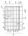
- the processing unit 106 may be configured and/or programed to generate an overlay map 400 which graphically superimposes the subsurface defect map 116 over the risk map 216, 302 as illustrated in Figs. 7 and 8 .
- the overlay map 400 may provide zoomed in images of the subsurface defect 20, dimensions of the subsurface defect 20 and/or location dimensions of the subsurface defect 20 on the hot gas path component 14.
- the hot gas path component 14 During inspection of the hot gas path component 14 such as the combustion liner 200 or the transition duct 300, the hot gas path component 14 is secured to the fixture 114. Thermal energy may be applied to the TBC 10 and/or to the hot gas component 14 using the thermal energy source 110.
- the infrared detection device 102 captures the infrared images 104 of the TBC 10 over a period of time as the thermal energy dissipates from the TBC 10.
- the actuatable mechanism 108 may be used to translate the infrared imaging device 102 to capture infrared images 104 of any portion of hot gas path component 14 having TBC 10.
- the processing unit 106 analyzes the infrared images 104 using the hardware and/or software that is designed to detect the subsurface defects 20 in the TBC 10 without removing the thermal insulation coat 18. The processing unit 106 may then stich the infrared images 104 together to generate the subsurface defect map 116 of the hot gas path component 14. The processing unit 106 and/or a technician may generate an overlay map 400 by superimposing the subsurface defect map 116 over the risk map 216, 302 to determine whether the subsurface defect 20 falls within a high risk location 218, 318 a medium risk location 220, 320 or a low risk location 222, 322 on the hot gas path component 14. For example, as shown in Fig.
- one subsurface defect 20 is identified within the combustion portion 204, and another subsurface defect is identified within the hot gas portion 206 of the combustion liner 200.
- one subsurface defect 20 is identified within the transition portion 310 along one of the pair of opposing side portions 316, and a second subsurface defect 20 is identified within the conical portion 308 along one of the opposing side portions 316.
- the processing unit 106 is configured and/or programed to compare the size and/or the location of the subsurface defect 20 to one or more allowable inspection limits that are inputted and/or stored in the processing unit 106 for the particular hot gas path component 14.
- the allowable inspection limits may be based on one or more of part history, prior subsurface defect maps, operating environment of the hot gas component 14, prior visual inspection data that has been inputted into the processing unit 106, customer provided limit requirements, TBC life curves, TBC composition, base metal composition, empirical damage information, bond-coat composition and/or calculated or empirical stress-strain levels and creep levels.
- the processing unit 106 is configured and/or programed to compare the subsurface defects 20 to the allowable inspection limits to generate a pass/fail or go/no-go report for the hot gas path component 14.
- method 600 for qualifying usability risk associated with subsurface defects 20 in the TBC 10 disposed on the hot gas path component 14 such as the combustion liner 200 and/or the transition duct 300.
- method 600 includes at step 602 generating the subsurface defect map 116 of the TBC 10 disposed on the hot gas path component 14. Step 602 may be performed using the infrared detection device 102 and the processing unit 106.
- Step 602 may further include transferring energy such as thermal or ultrasonic energy to at least one of the TBC 10 or the hot gas path component 14, capturing a plurality of time lapse infrared images 104 of the TBC 10 using the infrared imaging device 102, transferring the infrared images 104 to the processing unit 106, and stitching the plurality of infrared images 104 together to provide the continuous subsurface defect map 116.
- the method 600 includes generating the risk map 216, 302 of the hot gas component 14.
- the risk map 216, 302 may be generated using the processing unit 106 or the risk map 216, 302 may be provided as a printed image.
- Step 604 may further include inputting into the processing unit 106 at least one of stress-strain data, creep data, thermal fatigue data, mechanical fatigue data, temperature profile data or base metal properties of the hot gas path component.
- the method 600 includes superimposing the subsurface defect map 116 over the risk map 216, 302 to determine the risk level of the subsurface defect 20 based on the location of the subsurface defect 20 on the risk map 216, 302. Step 606 may also be performed using the processing unit 106.
- the method 600 further includes comparing the subsurface defect 20 to the allowable inspection limits defined at the subsurface defect 20 location on the risk map 216, 302.
- Step 608 may be performed using the processing unit 106.
- Step 608 may further include inputting into the processing unit 106 at least one of part history, prior subsurface defect maps, operating environment of the hot gas component, prior visual inspection data, customer provided limit requirements, thermal barrier coating life curves, thermal barrier coating composition, base metal composition, empirical damage information, stress-strain levels or creep levels.
- the method 600 includes qualifying the usability risk associated with continued use of the thermal barrier coating.
- Step 610 may be performed using the information contained in the subsurface defect map 116, the risk map 216, 302 and/or the inspection limits.
- Step 610 may be performed using the processing unit 106.
- Step 610 may include using the processing unit to generate a pass/fail report based on the inspection limits.
- the method 600 may further include translating the infrared imaging device 102 using the actuatable mechanism 108 to capture a plurality of infrared images 104 of the TBC 10, and using the processing unit 106 to stitch the plurality of infrared images 104 to form the continuous subsurface defect map 116.
Landscapes
- General Health & Medical Sciences (AREA)
- General Physics & Mathematics (AREA)
- Life Sciences & Earth Sciences (AREA)
- Chemical & Material Sciences (AREA)
- Analytical Chemistry (AREA)
- Biochemistry (AREA)
- Immunology (AREA)
- Physics & Mathematics (AREA)
- Health & Medical Sciences (AREA)
- Pathology (AREA)
- Investigating Or Analyzing Materials Using Thermal Means (AREA)
- Investigating Materials By The Use Of Optical Means Adapted For Particular Applications (AREA)
- Radiation Pyrometers (AREA)
- Investigating Or Analysing Materials By Optical Means (AREA)
Abstract
Description
- The present invention relates to a system and a method for qualifying usability risk associated with subsurface defects in a multilayer coating. In particular, the present invention involves using infrared technology to determine size and location of subsurface defects in a multilayer coating such as a thermal barrier coating to qualify usability risk associated with continued use of the multilayer coating.
- A combustion section of a gas turbine generally includes a plurality of combustors that are arranged in an annular array around an outer casing such as a compressor discharge casing. Pressurized air flows from a compressor to the compressor discharge casing and is routed to each combustor. Fuel from a fuel nozzle is mixed with the pressurized air in each combustor to form a combustible mixture within a primary combustion zone of the combustor. The combustible mixture is burned to produce hot combustion gases having a high pressure and high velocity. The combustion gases are routed towards an inlet of a turbine of the gas turbine through a hot gas path that is at least partially defined by an annular combustion liner and/or an annular transition duct. The hot gas path extends through the turbine and terminates at an outlet of the turbine.
- The constant demand for increased operating temperatures in gas turbine engines has necessitated the development of various coating materials such as ceramics that can be applied to the various hot gas paths components such as the combustion liner, the transition duct and/or turbine nozzles and turbine blades to insulate those components from the heat contained in the combustion gases, thereby extending the life of those components. These coatings are known in the art as thermal barrier coatings (TBC).
- A thermal barrier coating typically comprises at least one layer of a refractory or thermally insulating material having a low thermal conductivity such as about 1-3 W/(m)(K). The coating material may be applied by one of known deposition techniques such as a thermal or plasma spray process or a physical vapor deposition process. Typically, a thermal barrier coating is applied in multiple layers. In particular applications, a bond-coat is applied to an inner or hot side surface of the liner or transition duct. The bond-coat provides a layer which adheres well to the underlying alloy and that provides protection against oxidation of the alloy. The refractory or thermal insulation coat is then applied over the bond-coat. Some thermal barrier coatings may also include an intermediate layer or interlayer that is applied over the bond-coat. The interlayer may provide improved adhesion for the final thermal insulating coat.
- Despite great care taken during manufacture to ensure adhesion of the thermal insulation coat to the bond-coat, thermal cycling eventually leads to subsurface defects in the thermal barrier coating known as delamination or disbonding. Delamination generally leads to spallation that eventually exposes the underlying alloy to extreme temperatures that may impact the durability of the liner and/or transition duct. As a result, the thermal barrier coating must be inspected for subsurface defects during scheduled maintenance or planned outages of the gas turbine. Typically, the thermal barrier coating is stripped and replaced after a predetermined number of inspection cycles, in part due to limitations of many current inspection processes.
- Removal and reapplication of the thermal barrier coating significantly increases the time required to inspect the hot gas path component and contributes substantially to the overall cost of inspection/repair. Therefore, there is a continued need to provide a non-destructive method for determining size and location of subsurface defects in the thermal barrier coating to qualify the risk associated with continued use of the thermal barrier coating.
- Aspects and advantages of the invention are set forth below in the following description, or may be obvious from the description, or may be learned through practice of the invention.
- One embodiment of the present invention is a system for qualifying usability risk associated with subsurface defects in a multilayer coating. The system includes a component having a multilayer coating, an infrared detection device for capturing infrared images of the multilayered coating, a processing unit in electronic communication with the infrared detection device where the processing unit generates a subsurface defect map of the multilayer coating based on the infrared images. The system further includes a risk map of the component.
- Another embodiment of the present invention is a system for qualifying usability risk associated with subsurface defects in a thermal barrier coating of a hot gas path component. The system includes a hot gas path component having a thermal barrier coating, a thermal energy source, an infrared detection device for capturing infrared images of the thermal barrier coating and a processing unit that is in electronic communication with the infrared detection device. The processing unit is configured to generate a subsurface defect map of the thermal barrier coating based on the infrared images. The system further includes a risk map of the hot gas path component and an overlay map comprising of the subsurface defect map and the risk map.
- The present invention may also include a method for qualifying usability risks associated with subsurface defects in a thermal barrier coating of a hot gas path component. The method comprises generating a subsurface defect map of the thermal barrier coating, generating a risk map of the hot gas component and superimposing the subsurface defect map over the risk map to determine a risk level of the subsurface defect. The method further includes comparing the subsurface defect to allowable inspection limits and qualifying usability risks associated with continued use of the thermal barrier coating based on the comparison to the allowable inspection limits.
- Those of ordinary skill in the art will better appreciate the features and aspects of such embodiments, and others, upon review of the specification.
- A full and enabling disclosure of the present invention, including the best mode thereof to one skilled in the art, is set forth more particularly in the remainder of the specification, including reference to the accompanying figures, in which:
-
Fig. 1 provides a cross section side view of a typical thermal barrier coating within the scope of the present disclosure; -
Fig. 2 provides a schematic diagram of a system for qualifying usability risk associated with subsurface defects in a thermal barrier coating according to one embodiment of the present disclosure; -
Fig. 3 provides a perspective view of a combustion liner as may be incorporated into one or more embodiments of the present disclosure; -
Fig. 4 provides an exemplary risk map of the combustion liner as shown inFig. 3 , according to one embodiment of the present disclosure; -
Fig. 5 provides a perspective view of a transition duct as may be incorporated into one or more embodiments of the present disclosure; -
Fig. 6 provides an exemplary risk map of the transition duct as shown inFig. 5 , according to one embodiment of the present disclosure; -
Fig. 7 provides an exemplary overlay map including the risk map as shown inFig. 4 , according to one embodiment of the present disclosure; and -
Fig. 8 provides an exemplary overlay map including the risk map as shown inFig. 6 according to one embodiment of the present disclosure. - Reference will now be made in detail to present embodiments of the invention, one or more examples of which are illustrated in the accompanying drawings. The detailed description uses numerical and letter designations to refer to features in the drawings. Like or similar designations in the drawings and description have been used to refer to like or similar parts of the invention. As used herein, the term "radially" refers to the relative direction that is substantially perpendicular to an axial centerline of a particular component, and the term "axially" refers to the relative direction that is substantially parallel to an axial centerline of a particular component.
- Each example is provided by way of explanation of the invention, not limitation of the invention. In fact, it will be apparent to those skilled in the art that modifications and variations can be made in the present invention without departing from the scope or spirit thereof. For instance, features illustrated or described as part of one embodiment may be used on another embodiment to yield a still further embodiment. Thus, it is intended that the present invention covers such modifications and variations as come within the scope of the appended claims and their equivalents. Although exemplary embodiments of the present invention will be described generally in the context of a thermal barrier coating disposed on a combustion liner and/or a transition duct for a gas turbine for purposes of illustration, one of ordinary skill in the art will readily appreciate that embodiments of the present invention may be applied to any component having a multilayered thermal coating such as the thermal barrier coating that comes into contact with combustion gases.
- Referring now to the drawings, wherein identical numerals indicate the same elements throughout the figures,
Fig. 1 illustrates a cross section side view of a typical multilayer coating such as athermal barrier coating 10 herein referred to as "TBC 10". As shown inFig. 1 , theTBC 10 may be disposed on abase metal 12 of a hotgas path component 14 of a gas turbine such as a combustion liner or a transition duct. Although the multilayer coating in the present invention is described as a thermal barrier coating (TBC), it should be obvious to one of ordinary skill in the art that the invention as described herein may be applied to any multilayer coating. As shown inFig. 1 , theTBC 10 is generally applied in multiple layers. A first layer or bond-coat 16 is applied directly to thebase metal 12. A second layer orthermal insulation coat 18 is disposed over the bond-coat 16. A typical bond-coat 16 is composed of a metallic material such as nickel or cobalt that is suitable for adhesion to thebase metal 12. A typicalthermal insulation coat 18 is composed of yttria-stabilized zirconia which is known in the art for having low thermal conductivity while remaining stable at nominal operating temperatures of the gas turbine. - As the hot
gas path component 14 cycles through various thermal transients such as during start-up and shut-down of the gas turbine thethermal insulation coat 18 will tend to disbond or delaminate from the bond-coat 14, thereby creating asubsurface defect 20 in theTBC 10. Thesubsurface defect 20 may result in spallation of thethermal insulation coat 18, thereby compromising the effectiveness of theTBC 10 and/or limiting the durability of the hotgas path component 14. Thesubsurface defect 20 is generally difficult to detect without stripping thethermal insulation coating 20 from the hotgas path component 14. -
Fig. 2 provides a perspective view of asystem 100 for qualifying usability risk associated with continued use of theTBC 10 with thesubsurface defect 20 in theTBC 10, herein referred to as the "system 100". As used herein, the term "usability risk" includes risks associated with spallation and/or failure of theTBC 10 which may result in damage to and/or failure of thehot gas component 14. As shown, thesystem 100 includes aninfrared detection device 102 for providinginfrared images 104 of thethermal barrier coating 10 to aprocessing unit 106. Theprocessing unit 106 is in electronic communication with theinfrared detection device 102. In one embodiment, theinfrared detection device 102 is coupled to anactuatable mechanism 108 such as a robotic arm that manipulates theinfrared detection device 102 in at least one of an axial, radial or tangential direction to capture multipleinfrared images 104 of theTBC 10 across multiple locations of the hotgas path component 14. - In one embodiment, the
system 100 includes athermal energy source 110 such as a flash lamp or a laser for transferring thermal energy to theTBC 10 and/or the hotgas path component 14. Thesystem 100 may further include adisplay 112 such as a CRT, LCD or plasma monitor that is electronically connected to theprocessing unit 106 for displaying theinfrared images 104 and/or other information. In particular embodiments, thesystem 100 further includes afixture 114 to support the hotgas path component 14 during inspection. - The
infrared detection device 102 may include any imaging device such as an infrared camera that is capable of capturing theinfrared images 104 of theTBC 10 and electronically transferring theinfrared images 104 to theprocessing unit 106. Theprocessing unit 106 comprises hardware circuitry and software that enables theprocessing unit 106 to process theinfrared images 104 and detect thesubsurface defect 20 without removing thethermal insulation coat 18. For example, theprocessing unit 106 may be configured and/or programed to analyze theinfrared images 104 to measure various infrared wavelengths and/or changes in infrared wavelengths with respect to time to determine the presence of and the length, width and location of thesubsurface defect 20 on the hotgas path component 14. In particular embodiments, theprocessing unit 106 is configured and/or programmed to stitch a plurality of theinfrared images 104 together to generate a continuous two dimensional (2-D)subsurface defect map 116 of thehot gas component 14. Thesubsurface defect map 116 provides location and size of thesubsurface defect 20 on a 2-D image of the particular hotgas path component 14. As appreciated by those skilled in the art, theprocessing unit 106 may include a range of circuitry types, such as a microprocessor, a programmable logic controller, a logic module, etc. -
Fig. 3 provides a perspective view of an exemplary hotgas path component 14 as may be incorporated within the scope of this disclosure. As shown, the hotgas path component 14 may comprise anannular combustion liner 200. Thecombustion liner 200 generally includes aforward portion 202, acombustion portion 204 downstream from theforward portion 202, agas path portion 206 that extends downstream from thecombustion portion 204, anaft portion 208 downstream from thegas path portion 206 and aweld line portion 210 that extends between thegas path portion 206 and theaft end portion 208. Aninner surface 212 of thecombustion liner 200 is coated with theTBC 10 to protect the base metal of thecombustion liner 200 from high temperature combustion gases. Thecombustion portion 204 may also includevarious openings 214 for inserting components such as a spark igniter, a cross-fire tube or a flame detector into thecombustion liner 200. - In particular embodiments, as shown in
Fig. 4 thesystem 100 further includes arisk map 216. Therisk map 216 is a two dimensional (2-D) map of the hotgas path component 14 that identifies areas ofhigh risk 218,medium risk 220 andlow risk 222 associated with continued use theTBC 10 with a knownsubsurface defect 20. Therisk map 216 may comprise of a printed image that is used in conjunction with the subsurface defect map 116 (Fig. 2 ) that is generated by theprocessing unit 106. Thesubsurface defect map 116 may be positioned on top of therisk map 216 to determine the location of thedefect 20 and the risk level associated with thedefect 20 given its location on therisk map 216. - In one embodiment, the
processing unit 106 is configured and/or programed to generate the two dimensional (2-D) risk map of the particular hotgas path component 14. For example,Fig. 4 represents anexemplary risk map 216 of thecombustion liner 200 as shown inFig. 3 , according to one embodiment of the present invention. In particular embodiments, theprocessing unit 106 is configured and/or programed to generate therisk map 216 based at least one of the following: stress-strain data, creep data, thermal/mechanical fatigue data, temperature profile data, TBC thermal/mechanical properties, base metal thermal/mechanical properties or bond-coat properties of the particular hotgas path component 14, any or all of which may be based on empirical data such as field reports and/or inspection reports for the particularhot gas component 14, hand calculations and/or finite element analysis of the particular hotgas path component 14. - As shown, the
risk map 216 identifies areas ofhigh risk 218,medium risk 220 andlow risk 222 with regards to location on the particular hotgas path component 14. The risk level is generally based on susceptibility to thermal/mechanical damage to the base metal of the hotgas path component 12 due to failure or a compromised condition of theTBC 10. For example, as shown inFig. 4 , areas ofhigh risk 218 on thecombustion liner 200 are identified at thecombustion portion 204 and at theweld line 210, an area ofmedium risk 220 is identified at thehot gas portion 206 and areas oflow risk 222 are identified at the forward portion andaft portion combustion liner 200. - In other embodiments, the hot
gas path component 14 may comprise a transition duct.Fig. 5 provides a perspective view of anexemplary transition duct 300 of a gas turbine according to one embodiment of the present invention, andFig. 6 provides a correspondingexemplary risk map 302 for thetransition duct 300 according to one embodiment. As shown inFig. 5 , thetransition duct 300 generally includes aforward portion 304, a mountingportion 306 that corresponds to an area where the transition duct is mounted to the gas turbine, a generallyconical portion 308 and atransition portion 310 which corresponds to a portion of thetransition duct 300 where the transition duct transitions to a non-circular cross section. Because thetransition duct 300 is not completely conical or circular, therisk map 302 may be further divided to represent abottom portion 312, atop portion 314 and a pair of opposingside wall portions 316 of thetransition duct 300. - For example, as shown in
Fig. 6 , therisk map 302 may identify areas ofhigh risk 318 at theconical portion 308 along thebottom portion 312 and at thetransition portion 310 along thebottom portion 312 and along the pair of opposingside portions 316 of thetransition duct 300. Areas ofmedium risk 320 are identified at the mountingportion 306 along thebottom portion 312 and at thetransition portion 310 along thetop portion 314 of thetransition duct 300. Areas oflow risk 322 are identified at theforward end portion 304, at the mountingportion 306 along the top and pair of opposingside portions conical portion 308 along the top and pair of opposingside portions - As illustrated in
Figs. 7 and8 , theprocessing unit 106 may be configured and/or programed to generate anoverlay map 400 which graphically superimposes thesubsurface defect map 116 over therisk map Figs. 7 and8 . Theoverlay map 400 may provide zoomed in images of thesubsurface defect 20, dimensions of thesubsurface defect 20 and/or location dimensions of thesubsurface defect 20 on the hotgas path component 14. - During inspection of the hot
gas path component 14 such as thecombustion liner 200 or thetransition duct 300, the hotgas path component 14 is secured to thefixture 114. Thermal energy may be applied to theTBC 10 and/or to thehot gas component 14 using thethermal energy source 110. Theinfrared detection device 102 captures theinfrared images 104 of theTBC 10 over a period of time as the thermal energy dissipates from theTBC 10. Theactuatable mechanism 108 may be used to translate theinfrared imaging device 102 to captureinfrared images 104 of any portion of hotgas path component 14 havingTBC 10. - The
processing unit 106 analyzes theinfrared images 104 using the hardware and/or software that is designed to detect thesubsurface defects 20 in theTBC 10 without removing thethermal insulation coat 18. Theprocessing unit 106 may then stich theinfrared images 104 together to generate thesubsurface defect map 116 of the hotgas path component 14. Theprocessing unit 106 and/or a technician may generate anoverlay map 400 by superimposing thesubsurface defect map 116 over therisk map subsurface defect 20 falls within ahigh risk location 218, 318 amedium risk location low risk location gas path component 14. For example, as shown inFig. 7 , onesubsurface defect 20 is identified within thecombustion portion 204, and another subsurface defect is identified within thehot gas portion 206 of thecombustion liner 200. As another example, as shown inFig. 8 , onesubsurface defect 20 is identified within thetransition portion 310 along one of the pair of opposingside portions 316, and asecond subsurface defect 20 is identified within theconical portion 308 along one of the opposingside portions 316. - The
processing unit 106 is configured and/or programed to compare the size and/or the location of thesubsurface defect 20 to one or more allowable inspection limits that are inputted and/or stored in theprocessing unit 106 for the particular hotgas path component 14. The allowable inspection limits may be based on one or more of part history, prior subsurface defect maps, operating environment of thehot gas component 14, prior visual inspection data that has been inputted into theprocessing unit 106, customer provided limit requirements, TBC life curves, TBC composition, base metal composition, empirical damage information, bond-coat composition and/or calculated or empirical stress-strain levels and creep levels. Theprocessing unit 106 is configured and/or programed to compare thesubsurface defects 20 to the allowable inspection limits to generate a pass/fail or go/no-go report for the hotgas path component 14. - The various embodiments of the
system 100 as described herein and as illustrated inFigs. 2 through 8 provides amethod 600 for qualifying usability risk associated withsubsurface defects 20 in theTBC 10 disposed on the hotgas path component 14 such as thecombustion liner 200 and/or thetransition duct 300. As shown inFig. 9 ,method 600 includes atstep 602 generating thesubsurface defect map 116 of theTBC 10 disposed on the hotgas path component 14. Step 602 may be performed using theinfrared detection device 102 and theprocessing unit 106. Step 602 may further include transferring energy such as thermal or ultrasonic energy to at least one of theTBC 10 or the hotgas path component 14, capturing a plurality of time lapseinfrared images 104 of theTBC 10 using theinfrared imaging device 102, transferring theinfrared images 104 to theprocessing unit 106, and stitching the plurality ofinfrared images 104 together to provide the continuoussubsurface defect map 116. Atstep 604 themethod 600 includes generating therisk map hot gas component 14. Therisk map processing unit 106 or therisk map processing unit 106 at least one of stress-strain data, creep data, thermal fatigue data, mechanical fatigue data, temperature profile data or base metal properties of the hot gas path component. - At 606 the
method 600 includes superimposing thesubsurface defect map 116 over therisk map subsurface defect 20 based on the location of thesubsurface defect 20 on therisk map processing unit 106. - At
step 608 themethod 600 further includes comparing thesubsurface defect 20 to the allowable inspection limits defined at thesubsurface defect 20 location on therisk map processing unit 106. Step 608 may further include inputting into theprocessing unit 106 at least one of part history, prior subsurface defect maps, operating environment of the hot gas component, prior visual inspection data, customer provided limit requirements, thermal barrier coating life curves, thermal barrier coating composition, base metal composition, empirical damage information, stress-strain levels or creep levels. - At
step 610, themethod 600 includes qualifying the usability risk associated with continued use of the thermal barrier coating. Step 610 may be performed using the information contained in thesubsurface defect map 116, therisk map processing unit 106. Step 610 may include using the processing unit to generate a pass/fail report based on the inspection limits. Themethod 600 may further include translating theinfrared imaging device 102 using theactuatable mechanism 108 to capture a plurality ofinfrared images 104 of theTBC 10, and using theprocessing unit 106 to stitch the plurality ofinfrared images 104 to form the continuoussubsurface defect map 116. This written description uses examples to disclose the invention, including the best mode, and also to enable any person skilled in the art to practice the invention, including making and using any devices or systems and performing any incorporated methods. The patentable scope of the invention is defined by the claims, and may include other examples that occur to those skilled in the art. Such other examples are intended to be within the scope of the claims if they include structural elements that do not differ from the literal language of the claims, or if they include equivalent structural elements with insubstantial differences from the literal language of the claims. - Various aspects and embodiments of the present invention are defined by the following numbered clauses:
- 1. A system for qualifying usability risk associated with subsurface defects in a multilayer coating, comprising:
- a. a component having a multilayer coating;
- b. an infrared detection device for capturing infrared images of the multilayered coating;
- c. a processing unit in electronic communication with the infrared detection device, wherein the processing unit generates a subsurface defect map of the multilayer coating based on the infrared images; and
- d. a risk map of the component.
- 2. The system as in clause 1, wherein the multilayer coating comprises a thermal barrier coating.
- 3. The system as in any preceding clause, further comprising an overlay map that provides a graphical display of the subsurface defect map superimposed onto the risk map.
- 4. The system as in any preceding clause, wherein the processing unit generates a pass/fail report for the thermal barrier coating.
- 5. The system as in any preceding clause, wherein component is one of a combustion liner or a transition duct.
- 6. The system as in any preceding clause, further comprising a thermal energy source for transferring thermal energy to the thermal barrier coating.
- 7. The system as in any preceding clause, wherein the thermal barrier coating includes a bond-coat disposed on the hot gas path component and a thermal insulation coat that covers the bond-coat, wherein the subsurface defect map defines at least one of size or location of a subsurface defect between the bond-coat and the thermal insulation coat.
- 8. The system as in any preceding clause, wherein the processing unit compares at least one of size or location of the subsurface defect to allowable inspection limits to generate a pass/fail report.
- 9. The system as in any preceding clause, wherein the allowable inspection limits are based on at least one of part history, prior subsurface defect maps, operating environment of the hot gas component, prior visual inspection data, customer provided limit requirements, thermal barrier coating life curves, base metal composition, empirical damage information, stress-strain levels or creep levels.
- 10. A system for qualifying usability risk associated with subsurface defects in a thermal barrier coating, comprising:
- a. a hot gas path component having a thermal barrier coating;
- b. a thermal energy source;
- c. an infrared detection device for capturing infrared images of the thermal barrier coating;
- d. a processing unit in electronic communication with the infrared detection device, wherein the processing unit generates a subsurface defect map of the thermal barrier coating based on the infrared images;
- e. a risk map of the hot gas path component; and
- f. an overlay map comprising of the subsurface defect map and the risk map.
- 11. The system as in any preceding clause, wherein the overlay map provides a graphical display of the subsurface defect map superimposed onto the risk map.
- 12. The system as in any preceding clause, wherein the processing unit compares at least one of size or location of the subsurface defect to allowable inspection limits to generate a pass/fail report.
- 13. The system as in any preceding clause, wherein the thermal barrier coating includes a bond-coat disposed on the hot gas path component and a thermal insulation coat that covers the bond-coat, wherein the subsurface defect map identifies at least one of size or location of a subsurface defect between the bond-coat and the thermal insulation coat.
- 14. The system as in any preceding clause, further comprising allowable inspection limits that are provided to the processing unit, wherein the allowable inspection limits are based on at least one of part history, prior subsurface defect maps, operating environment of the hot gas component, prior visual inspection data, customer provided limit requirements, thermal barrier coating life curves, base metal composition, empirical damage information, stress-strain levels or creep levels.
- 15. The system as in any preceding clause, further comprising an actuatable mechanism coupled to the infrared detection device for translating the infrared detection device across a surface of the hot gas path component, wherein the surface is at least partially covered by the thermal barrier coating.
- 16. A method for qualifying usability risk associated with subsurface defects in a thermal barrier coating, the method comprising:
- a. generating a subsurface defect map of the thermal barrier coating;
- b. generating a risk map of the hot gas component;
- c. superimposing the subsurface defect map over the risk map to determine a risk level of the subsurface defect;
- d. comparing the subsurface defect to allowable inspection limits; and
- e. qualifying usability risk associated with continued use of the thermal barrier coating based on the comparison to the allowable inspection limits.
- 17. The method as in any preceding clause, further comprising generating a pass/fail report based on the risk level and the allowable inspection limits.
- 18. The method as in any preceding clause, wherein the steps of generating a subsurface defect map, generating a risk map, superimposing the subsurface defect map over the risk map and comparing the subsurface defect to allowable inspection limits are performed using a processing unit.
- 19. The method as in any preceding clause, wherein the step of comparing the subsurface defect to allowable inspection limits includes inputting into a processing unit at least one of part history, prior subsurface defect maps, operating environment of the hot gas component, prior visual inspection data, customer provided limit requirements, thermal barrier coating life curves, thermal barrier coating composition, base metal composition, empirical damage information, stress-strain levels or creep levels.
- 20. The method as in any preceding clause, wherein the step of generating a subsurface defect map comprises:
- a. transferring thermal energy to at least one of the thermal barrier coating or the hot gas path component;
- b. capturing a plurality of time lapse infrared images of the thermal barrier coating using the infrared imaging device; and
- c. transferring the infrared images to a processing unit.
Claims (15)
- A system (100) for qualifying usability risk associated with subsurface defects (20) in a multilayer coating (10), comprising:a. a component (14) having a multilayer coating (10);b. an infrared detection device (102) for capturing infrared images (104) of the multilayered coating (10);c. a processing unit (106) in electronic communication with the infrared detection device (102), wherein the processing unit (106) generates a subsurface defect map (116) of the multilayer coating based on the infrared images (104); andd. a risk map (216) of the component (14).
- The system as in claim 1, further comprising an overlay map (400) that provides a graphical display of the subsurface defect map (116) superimposed onto the risk map (216).
- The system as in claim 1 or claim 2, wherein the processing unit (106) generates a pass/fail report for the thermal barrier coating (10).
- The system as in claim 1, 2 or 3, wherein component (14) is one of a combustion liner (200) or a transition duct (300).
- The system as in any preceding claim, wherein the multilayer coating comprises a thermal barrier coating (10).
- The system as in claim 5, further comprising a thermal energy source (110) for transferring thermal energy to the thermal barrier coating (10).
- The system as in claim 6, wherein the thermal barrier coating (10) includes a bond-coat (16) disposed on the hot gas path component (14) and a thermal insulation coat (18) that covers the bond-coat (16), wherein the subsurface defect map (116) defines at least one of size or location of a subsurface defect (20) between the bond-coat (16) and the thermal insulation coat (18).
- The system as in claim 6 or claim 7, wherein the processing unit (106) compares at least one of size or location of the subsurface defect (20) to allowable inspection limits to generate a pass/fail report, wherein, preferably, the allowable inspection limits are based on at least one of part history, prior subsurface defect maps, operating environment of the hot gas component, prior visual inspection data, customer provided limit requirements, thermal barrier coating life curves, base metal composition, empirical damage information, stress-strain levels or creep levels.
- A system for qualifying usability risk associated with subsurface defects (20) in a thermal barrier coating (10) including the system as in any preceding claim, and comprising:a. a hot gas path component (14) having a thermal barrier coating (10);b. a thermal energy source (110);c. an infrared detection device (102) for capturing infrared images (104) of the thermal barrier coating (10);d. a processing unit (106) in electronic communication with the infrared detection device (102), wherein the processing unit (106) generates a subsurface defect map (116) of the thermal barrier coating (10) based on the infrared images (104);e. a risk map (216) of the hot gas path component (14); andf. an overlay map (400) comprising of the subsurface defect map and the risk map.
- The system as in claim 9, further comprising an actuatable mechanism (108) coupled to the infrared detection device (102) for translating the infrared detection device (102) across a surface of the hot gas path component (14), wherein the surface is at least partially covered by the thermal barrier coating (10).
- A method (600) for qualifying usability risk associated with subsurface defects in a thermal barrier coating, the method comprising:a. generating (602) a subsurface defect map of the thermal barrier coating;b. generating (604) a risk map of the hot gas component;c. superimposing (606) the subsurface defect map over the risk map to determine a risk level of the subsurface defect;d. comparing (608) the subsurface defect to allowable inspection limits; ande. qualifying (610) usability risk associated with continued use of the thermal barrier coating based on the comparison to the allowable inspection limits.
- The method as in claim 11, further comprising generating (610) a pass/fail report based on the risk level and the allowable inspection limits.
- The method as in claim 11 or claim 12, wherein the steps of generating (602) a subsurface defect map, generating a risk map, superimposing the subsurface defect map over the risk map and comparing the subsurface defect to allowable inspection limits are performed using a processing unit.
- The method as in claim 11, 12 or 13, wherein the step of comparing (608) the subsurface defect to allowable inspection limits includes inputting into a processing unit at least one of part history, prior subsurface defect maps, operating environment of the hot gas component, prior visual inspection data, customer provided limit requirements, thermal barrier coating life curves, thermal barrier coating composition, base metal composition, empirical damage information, stress-strain levels or creep levels.
- The method as in any one of claims 11 to 14, wherein the step of generating (602) a subsurface defect map comprises:a. transferring thermal energy to at least one of the thermal barrier coating or the hot gas path component;b. capturing a plurality of time lapse infrared images of the thermal barrier coating using the infrared imaging device; andc. transferring the infrared images to a processing unit.
Priority Applications (1)
| Application Number | Priority Date | Filing Date | Title |
|---|---|---|---|
| PL14163231T PL2790013T3 (en) | 2013-04-08 | 2014-04-02 | A system and method for qualifying usability risk associated with subsurface defects in a multilayer coating |
Applications Claiming Priority (1)
| Application Number | Priority Date | Filing Date | Title |
|---|---|---|---|
| US13/858,172 US8759770B1 (en) | 2013-04-08 | 2013-04-08 | System and method for qualifying usability risk associated with subsurface defects in a multilayer coating |
Publications (3)
| Publication Number | Publication Date |
|---|---|
| EP2790013A2 true EP2790013A2 (en) | 2014-10-15 |
| EP2790013A3 EP2790013A3 (en) | 2015-04-29 |
| EP2790013B1 EP2790013B1 (en) | 2020-03-18 |
Family
ID=50439209
Family Applications (1)
| Application Number | Title | Priority Date | Filing Date |
|---|---|---|---|
| EP14163231.5A Active EP2790013B1 (en) | 2013-04-08 | 2014-04-02 | A system and method for qualifying usability risk associated with subsurface defects in a multilayer coating |
Country Status (4)
| Country | Link |
|---|---|
| US (1) | US8759770B1 (en) |
| EP (1) | EP2790013B1 (en) |
| JP (1) | JP6362906B2 (en) |
| PL (1) | PL2790013T3 (en) |
Families Citing this family (21)
| Publication number | Priority date | Publication date | Assignee | Title |
|---|---|---|---|---|
| KR101301364B1 (en) * | 2012-01-31 | 2013-08-29 | 성균관대학교산학협력단 | Method for evaluating perfromance of thermal barrier coating |
| CN105319221A (en) * | 2014-05-30 | 2016-02-10 | 国网山西省电力公司电力科学研究院 | Conducting wire pressing connection quality detection method and conducting wire pressing connection quality detection apparatus |
| WO2016069085A1 (en) * | 2014-10-30 | 2016-05-06 | Bae Systems Information & Electronic Systems Integration Inc. | High resolution inspection device for casting defects using ir imaging |
| RU2578260C1 (en) * | 2014-12-24 | 2016-03-27 | Владимир Валентинович Липатников | Method for thermal nondestructive inspection of hidden defects of foamed insulating layer in articles with multilayer structure |
| EP3118422B1 (en) * | 2015-07-17 | 2018-12-05 | Ansaldo Energia IP UK Limited | Calibration block for inspection of gas turbine component and manufacturing method |
| GB2546957B (en) | 2015-11-13 | 2018-07-04 | Rolls Royce Plc | Surface inspection of an object using multiple images |
| US10815817B2 (en) | 2016-01-21 | 2020-10-27 | Raytheon Technologies Corporation | Heat flux measurement system |
| US10262404B2 (en) * | 2016-06-14 | 2019-04-16 | General Electric Company | Method and system for articulation of a visual inspection device |
| CN107917961A (en) * | 2017-09-21 | 2018-04-17 | 中国检验检疫科学研究院 | A kind of test method of in-service steel load-carrying construction part security |
| EP3987154A4 (en) * | 2019-06-24 | 2022-12-21 | Technion Research & Development Foundation Limited | MEASUREMENT OF THE THERMAL PROPERTIES OF COATINGS BY INDUCTION RADIOMETRY |
| CN110261437B (en) * | 2019-07-01 | 2021-10-29 | 重庆科技学院 | A Defect Survey Method for Natural Gas Station Pressure Equipment Based on Infrared Thermal Image |
| US11679898B2 (en) * | 2020-06-15 | 2023-06-20 | General Electric Company | Inspection and repair tool |
| US11810288B2 (en) | 2020-09-04 | 2023-11-07 | General Electric Company | Systems and methods for generating a single observation image to analyze coating defects |
| US11603593B2 (en) | 2020-09-04 | 2023-03-14 | General Electric Company | Systems and methods for automatic detection of coating defects |
| US12208925B2 (en) | 2020-10-29 | 2025-01-28 | General Electric Company | Systems and methods of servicing equipment |
| US12139109B2 (en) | 2020-10-29 | 2024-11-12 | General Electric Company | Systems and methods of servicing equipment |
| US11935290B2 (en) | 2020-10-29 | 2024-03-19 | Oliver Crispin Robotics Limited | Systems and methods of servicing equipment |
| US20220136405A1 (en) * | 2020-10-29 | 2022-05-05 | General Electric Company | Systems and methods of servicing equipment |
| US12511623B2 (en) | 2020-10-29 | 2025-12-30 | General Electric Company | Systems and methods of servicing equipment |
| US11992952B2 (en) | 2020-10-29 | 2024-05-28 | General Electric Company | Systems and methods of servicing equipment |
| US12447625B2 (en) | 2022-06-03 | 2025-10-21 | Oliver Crispin Robotics Limited | Systems and methods for aligning and localizing a tool |
Family Cites Families (36)
| Publication number | Priority date | Publication date | Assignee | Title |
|---|---|---|---|---|
| US3499153A (en) | 1967-01-09 | 1970-03-03 | Barnes Eng Co | Nondestructive testing of materials by infrared radiation |
| US5111048A (en) | 1990-09-27 | 1992-05-05 | General Electric Company | Apparatus and method for detecting fatigue cracks using infrared thermography |
| JP3007474B2 (en) * | 1991-04-19 | 2000-02-07 | 川崎重工業株式会社 | Ultrasonic inspection method and apparatus |
| JP3186866B2 (en) * | 1992-11-20 | 2001-07-11 | 株式会社東芝 | Method and apparatus for predicting deterioration / damage of structural member |
| US20020018510A1 (en) | 1996-07-31 | 2002-02-14 | Murphy John C. | Thermal-based methods for nondestructive evaluation |
| US6000844A (en) | 1997-03-04 | 1999-12-14 | The United States Of America As Represented By The Administrator Of The National Aeronautics And Space Administration | Method and apparatus for the portable identification of material thickness and defects using spatially controlled heat application |
| JP3670869B2 (en) * | 1998-10-30 | 2005-07-13 | 財団法人電力中央研究所 | Coating layer thermal resistance measurement method |
| US7083327B1 (en) | 1999-04-06 | 2006-08-01 | Thermal Wave Imaging, Inc. | Method and apparatus for detecting kissing unbond defects |
| US6394646B1 (en) | 1999-04-16 | 2002-05-28 | General Electric Company | Method and apparatus for quantitative nondestructive evaluation of metal airfoils using high resolution transient thermography |
| WO2001046660A1 (en) * | 1999-12-22 | 2001-06-28 | Siemens Westinghouse Power Corporation | Method and apparatus for measuring on line failure of turbine thermal barrier coatings |
| US7690840B2 (en) * | 1999-12-22 | 2010-04-06 | Siemens Energy, Inc. | Method and apparatus for measuring on-line failure of turbine thermal barrier coatings |
| JP2002071606A (en) * | 2000-08-29 | 2002-03-12 | Mitsubishi Heavy Ind Ltd | Non-destructive inspection device and its control device |
| US6730918B2 (en) | 2001-12-20 | 2004-05-04 | General Electric Company | Apparatus for determining past-service conditions and remaining life of thermal barrier coatings and components having such coatings |
| US6853926B2 (en) | 2002-06-05 | 2005-02-08 | Research Foundation Of Cuny | Systems and methods for non-destructively detecting material abnormalities beneath a coated surface |
| US6877894B2 (en) | 2002-09-24 | 2005-04-12 | Siemens Westinghouse Power Corporation | Self-aligning apparatus for acoustic thermography |
| JP2004156444A (en) * | 2002-11-01 | 2004-06-03 | Mitsubishi Heavy Ind Ltd | Thermal barrier coating degradation diagnosing method |
| US6838670B2 (en) | 2002-11-12 | 2005-01-04 | Siemens Westinghouse Power Corporation | Methods and system for ultrasonic thermographic non-destructive examination for enhanced defect determination |
| US6874932B2 (en) * | 2003-06-30 | 2005-04-05 | General Electric Company | Methods for determining the depth of defects |
| US7129492B2 (en) | 2003-07-29 | 2006-10-31 | Toyota Motor Manufacturing North America, Inc. | Systems and methods for inspecting coatings |
| US7220966B2 (en) | 2003-07-29 | 2007-05-22 | Toyota Motor Manufacturing North America, Inc. | Systems and methods for inspecting coatings, surfaces and interfaces |
| WO2007067601A2 (en) * | 2005-12-07 | 2007-06-14 | Meyer Tool, Inc. | Apparatus and method for analyzing relative outward flow characterizations of fabricated features |
| US7388204B2 (en) | 2005-12-07 | 2008-06-17 | Meyer Tool, Inc. | Apparatus and method for analyzing relative outward flow characterizations of fabricated features |
| US7409313B2 (en) | 2005-12-16 | 2008-08-05 | General Electric Company | Method and apparatus for nondestructive evaluation of insulative coating |
| US7689003B2 (en) | 2006-03-20 | 2010-03-30 | Siemens Energy, Inc. | Combined 2D and 3D nondestructive examination |
| US7432505B2 (en) | 2006-05-04 | 2008-10-07 | Siemens Power Generation, Inc. | Infrared-based method and apparatus for online detection of cracks in steam turbine components |
| US8288726B2 (en) | 2006-12-19 | 2012-10-16 | Weil Gary J | Remote sensing of subsurface artifacts by use of visual and thermal imagery |
| US8116990B2 (en) * | 2007-10-19 | 2012-02-14 | Ashok Koul | Method and system for real-time prognosis analysis and usage based residual life assessment of turbine engine components and display |
| JP5140892B2 (en) * | 2008-10-21 | 2013-02-13 | 西日本高速道路エンジニアリング四国株式会社 | Infrared thermal image analyzer |
| US8300232B2 (en) | 2009-08-19 | 2012-10-30 | Siemens Energy, Inc. | Method of measuring coating thickness using infrared light |
| US9080453B2 (en) * | 2010-03-17 | 2015-07-14 | Thermal Wave Imaging, Inc. | Thermographic detection of internal passageway blockages |
| CN102869973B (en) | 2010-04-23 | 2016-01-20 | 西门子公司 | For checking the checking system of turbo blade |
| US8510060B2 (en) * | 2010-06-07 | 2013-08-13 | General Electric Company | Life management system and method for gas turbine thermal barrier coatings |
| US8692887B2 (en) * | 2010-08-27 | 2014-04-08 | General Electric Company | Thermal imaging method and apparatus for evaluating coatings |
| US10704958B2 (en) * | 2010-10-21 | 2020-07-07 | Siemens Energy, Inc. | Method for monitoring a high-temperature region of interest in a turbine engine |
| US20120186260A1 (en) | 2011-01-25 | 2012-07-26 | General Electric Company | Transition piece impingement sleeve for a gas turbine |
| JP5705627B2 (en) * | 2011-04-18 | 2015-04-22 | 三菱重工業株式会社 | Heat-resistant member repair method, repair heat-resistant member |
-
2013
- 2013-04-08 US US13/858,172 patent/US8759770B1/en active Active
-
2014
- 2014-04-02 PL PL14163231T patent/PL2790013T3/en unknown
- 2014-04-02 EP EP14163231.5A patent/EP2790013B1/en active Active
- 2014-04-04 JP JP2014077417A patent/JP6362906B2/en active Active
Non-Patent Citations (1)
| Title |
|---|
| None |
Also Published As
| Publication number | Publication date |
|---|---|
| US8759770B1 (en) | 2014-06-24 |
| EP2790013B1 (en) | 2020-03-18 |
| JP6362906B2 (en) | 2018-07-25 |
| PL2790013T3 (en) | 2020-07-27 |
| EP2790013A3 (en) | 2015-04-29 |
| JP2014202476A (en) | 2014-10-27 |
Similar Documents
| Publication | Publication Date | Title |
|---|---|---|
| US8759770B1 (en) | System and method for qualifying usability risk associated with subsurface defects in a multilayer coating | |
| US11992952B2 (en) | Systems and methods of servicing equipment | |
| CN114511103B (en) | System and method for repairing equipment | |
| CN114511104B (en) | System and method for repairing equipment | |
| EP3992432B1 (en) | Systems and methods of servicing equipment | |
| US12511623B2 (en) | Systems and methods of servicing equipment | |
| CN114511107B (en) | System and method for repairing equipment | |
| EP3992430B1 (en) | Systems and methods of servicing a gas turbine engine | |
| CN114429225B (en) | System and method for repairing equipment | |
| CN114425777B (en) | System and method for servicing equipment | |
| US11874653B2 (en) | Systems and methods of servicing equipment | |
| EP3913188A1 (en) | Method for inspecting and repairing a ceramic matrix composite component in a gas turbine engine | |
| US10060830B2 (en) | In-situ system and method of determining coating integrity of turbomachinery components | |
| US8720257B2 (en) | Methods, systems and apparatus for detecting material defects in combustors of combustion turbine engines |
Legal Events
| Date | Code | Title | Description |
|---|---|---|---|
| PUAI | Public reference made under article 153(3) epc to a published international application that has entered the european phase |
Free format text: ORIGINAL CODE: 0009012 |
|
| 17P | Request for examination filed |
Effective date: 20140402 |
|
| AK | Designated contracting states |
Kind code of ref document: A2 Designated state(s): AL AT BE BG CH CY CZ DE DK EE ES FI FR GB GR HR HU IE IS IT LI LT LU LV MC MK MT NL NO PL PT RO RS SE SI SK SM TR |
|
| AX | Request for extension of the european patent |
Extension state: BA ME |
|
| PUAL | Search report despatched |
Free format text: ORIGINAL CODE: 0009013 |
|
| AK | Designated contracting states |
Kind code of ref document: A3 Designated state(s): AL AT BE BG CH CY CZ DE DK EE ES FI FR GB GR HR HU IE IS IT LI LT LU LV MC MK MT NL NO PL PT RO RS SE SI SK SM TR |
|
| AX | Request for extension of the european patent |
Extension state: BA ME |
|
| RIC1 | Information provided on ipc code assigned before grant |
Ipc: F01D 5/28 20060101ALI20150324BHEP Ipc: F01D 21/00 20060101ALI20150324BHEP Ipc: G01N 21/84 20060101AFI20150324BHEP Ipc: G01N 25/72 20060101ALI20150324BHEP Ipc: G01N 21/88 20060101ALI20150324BHEP |
|
| R17P | Request for examination filed (corrected) |
Effective date: 20151029 |
|
| RBV | Designated contracting states (corrected) |
Designated state(s): AL AT BE BG CH CY CZ DE DK EE ES FI FR GB GR HR HU IE IS IT LI LT LU LV MC MK MT NL NO PL PT RO RS SE SI SK SM TR |
|
| STAA | Information on the status of an ep patent application or granted ep patent |
Free format text: STATUS: EXAMINATION IS IN PROGRESS |
|
| 17Q | First examination report despatched |
Effective date: 20180103 |
|
| GRAP | Despatch of communication of intention to grant a patent |
Free format text: ORIGINAL CODE: EPIDOSNIGR1 |
|
| STAA | Information on the status of an ep patent application or granted ep patent |
Free format text: STATUS: GRANT OF PATENT IS INTENDED |
|
| INTG | Intention to grant announced |
Effective date: 20190925 |
|
| RIN1 | Information on inventor provided before grant (corrected) |
Inventor name: BAUMMER, JAMES CARROLL Inventor name: WOODS, STEVEN CHARLES |
|
| GRAS | Grant fee paid |
Free format text: ORIGINAL CODE: EPIDOSNIGR3 |
|
| GRAA | (expected) grant |
Free format text: ORIGINAL CODE: 0009210 |
|
| STAA | Information on the status of an ep patent application or granted ep patent |
Free format text: STATUS: THE PATENT HAS BEEN GRANTED |
|
| AK | Designated contracting states |
Kind code of ref document: B1 Designated state(s): AL AT BE BG CH CY CZ DE DK EE ES FI FR GB GR HR HU IE IS IT LI LT LU LV MC MK MT NL NO PL PT RO RS SE SI SK SM TR |
|
| REG | Reference to a national code |
Ref country code: GB Ref legal event code: FG4D |
|
| REG | Reference to a national code |
Ref country code: DE Ref legal event code: R096 Ref document number: 602014062429 Country of ref document: DE |
|
| REG | Reference to a national code |
Ref country code: AT Ref legal event code: REF Ref document number: 1246483 Country of ref document: AT Kind code of ref document: T Effective date: 20200415 Ref country code: IE Ref legal event code: FG4D |
|
| PG25 | Lapsed in a contracting state [announced via postgrant information from national office to epo] |
Ref country code: NO Free format text: LAPSE BECAUSE OF FAILURE TO SUBMIT A TRANSLATION OF THE DESCRIPTION OR TO PAY THE FEE WITHIN THE PRESCRIBED TIME-LIMIT Effective date: 20200618 Ref country code: RS Free format text: LAPSE BECAUSE OF FAILURE TO SUBMIT A TRANSLATION OF THE DESCRIPTION OR TO PAY THE FEE WITHIN THE PRESCRIBED TIME-LIMIT Effective date: 20200318 Ref country code: FI Free format text: LAPSE BECAUSE OF FAILURE TO SUBMIT A TRANSLATION OF THE DESCRIPTION OR TO PAY THE FEE WITHIN THE PRESCRIBED TIME-LIMIT Effective date: 20200318 |
|
| REG | Reference to a national code |
Ref country code: NL Ref legal event code: MP Effective date: 20200318 |
|
| PG25 | Lapsed in a contracting state [announced via postgrant information from national office to epo] |
Ref country code: HR Free format text: LAPSE BECAUSE OF FAILURE TO SUBMIT A TRANSLATION OF THE DESCRIPTION OR TO PAY THE FEE WITHIN THE PRESCRIBED TIME-LIMIT Effective date: 20200318 Ref country code: GR Free format text: LAPSE BECAUSE OF FAILURE TO SUBMIT A TRANSLATION OF THE DESCRIPTION OR TO PAY THE FEE WITHIN THE PRESCRIBED TIME-LIMIT Effective date: 20200619 Ref country code: LV Free format text: LAPSE BECAUSE OF FAILURE TO SUBMIT A TRANSLATION OF THE DESCRIPTION OR TO PAY THE FEE WITHIN THE PRESCRIBED TIME-LIMIT Effective date: 20200318 Ref country code: SE Free format text: LAPSE BECAUSE OF FAILURE TO SUBMIT A TRANSLATION OF THE DESCRIPTION OR TO PAY THE FEE WITHIN THE PRESCRIBED TIME-LIMIT Effective date: 20200318 Ref country code: BG Free format text: LAPSE BECAUSE OF FAILURE TO SUBMIT A TRANSLATION OF THE DESCRIPTION OR TO PAY THE FEE WITHIN THE PRESCRIBED TIME-LIMIT Effective date: 20200618 |
|
| REG | Reference to a national code |
Ref country code: LT Ref legal event code: MG4D |
|
| PG25 | Lapsed in a contracting state [announced via postgrant information from national office to epo] |
Ref country code: NL Free format text: LAPSE BECAUSE OF FAILURE TO SUBMIT A TRANSLATION OF THE DESCRIPTION OR TO PAY THE FEE WITHIN THE PRESCRIBED TIME-LIMIT Effective date: 20200318 |
|
| PG25 | Lapsed in a contracting state [announced via postgrant information from national office to epo] |
Ref country code: LT Free format text: LAPSE BECAUSE OF FAILURE TO SUBMIT A TRANSLATION OF THE DESCRIPTION OR TO PAY THE FEE WITHIN THE PRESCRIBED TIME-LIMIT Effective date: 20200318 Ref country code: SM Free format text: LAPSE BECAUSE OF FAILURE TO SUBMIT A TRANSLATION OF THE DESCRIPTION OR TO PAY THE FEE WITHIN THE PRESCRIBED TIME-LIMIT Effective date: 20200318 Ref country code: EE Free format text: LAPSE BECAUSE OF FAILURE TO SUBMIT A TRANSLATION OF THE DESCRIPTION OR TO PAY THE FEE WITHIN THE PRESCRIBED TIME-LIMIT Effective date: 20200318 Ref country code: PT Free format text: LAPSE BECAUSE OF FAILURE TO SUBMIT A TRANSLATION OF THE DESCRIPTION OR TO PAY THE FEE WITHIN THE PRESCRIBED TIME-LIMIT Effective date: 20200812 Ref country code: CZ Free format text: LAPSE BECAUSE OF FAILURE TO SUBMIT A TRANSLATION OF THE DESCRIPTION OR TO PAY THE FEE WITHIN THE PRESCRIBED TIME-LIMIT Effective date: 20200318 Ref country code: IS Free format text: LAPSE BECAUSE OF FAILURE TO SUBMIT A TRANSLATION OF THE DESCRIPTION OR TO PAY THE FEE WITHIN THE PRESCRIBED TIME-LIMIT Effective date: 20200718 Ref country code: RO Free format text: LAPSE BECAUSE OF FAILURE TO SUBMIT A TRANSLATION OF THE DESCRIPTION OR TO PAY THE FEE WITHIN THE PRESCRIBED TIME-LIMIT Effective date: 20200318 Ref country code: SK Free format text: LAPSE BECAUSE OF FAILURE TO SUBMIT A TRANSLATION OF THE DESCRIPTION OR TO PAY THE FEE WITHIN THE PRESCRIBED TIME-LIMIT Effective date: 20200318 |
|
| REG | Reference to a national code |
Ref country code: AT Ref legal event code: MK05 Ref document number: 1246483 Country of ref document: AT Kind code of ref document: T Effective date: 20200318 |
|
| REG | Reference to a national code |
Ref country code: DE Ref legal event code: R097 Ref document number: 602014062429 Country of ref document: DE |
|
| PG25 | Lapsed in a contracting state [announced via postgrant information from national office to epo] |
Ref country code: MC Free format text: LAPSE BECAUSE OF FAILURE TO SUBMIT A TRANSLATION OF THE DESCRIPTION OR TO PAY THE FEE WITHIN THE PRESCRIBED TIME-LIMIT Effective date: 20200318 |
|
| PLBE | No opposition filed within time limit |
Free format text: ORIGINAL CODE: 0009261 |
|
| STAA | Information on the status of an ep patent application or granted ep patent |
Free format text: STATUS: NO OPPOSITION FILED WITHIN TIME LIMIT |
|
| PG25 | Lapsed in a contracting state [announced via postgrant information from national office to epo] |
Ref country code: LU Free format text: LAPSE BECAUSE OF NON-PAYMENT OF DUE FEES Effective date: 20200402 Ref country code: ES Free format text: LAPSE BECAUSE OF FAILURE TO SUBMIT A TRANSLATION OF THE DESCRIPTION OR TO PAY THE FEE WITHIN THE PRESCRIBED TIME-LIMIT Effective date: 20200318 Ref country code: AT Free format text: LAPSE BECAUSE OF FAILURE TO SUBMIT A TRANSLATION OF THE DESCRIPTION OR TO PAY THE FEE WITHIN THE PRESCRIBED TIME-LIMIT Effective date: 20200318 Ref country code: DK Free format text: LAPSE BECAUSE OF FAILURE TO SUBMIT A TRANSLATION OF THE DESCRIPTION OR TO PAY THE FEE WITHIN THE PRESCRIBED TIME-LIMIT Effective date: 20200318 |
|
| REG | Reference to a national code |
Ref country code: BE Ref legal event code: MM Effective date: 20200430 |
|
| 26N | No opposition filed |
Effective date: 20201221 |
|
| PG25 | Lapsed in a contracting state [announced via postgrant information from national office to epo] |
Ref country code: BE Free format text: LAPSE BECAUSE OF NON-PAYMENT OF DUE FEES Effective date: 20200430 |
|
| PG25 | Lapsed in a contracting state [announced via postgrant information from national office to epo] |
Ref country code: IE Free format text: LAPSE BECAUSE OF NON-PAYMENT OF DUE FEES Effective date: 20200402 |
|
| PG25 | Lapsed in a contracting state [announced via postgrant information from national office to epo] |
Ref country code: SI Free format text: LAPSE BECAUSE OF FAILURE TO SUBMIT A TRANSLATION OF THE DESCRIPTION OR TO PAY THE FEE WITHIN THE PRESCRIBED TIME-LIMIT Effective date: 20200318 |
|
| PG25 | Lapsed in a contracting state [announced via postgrant information from national office to epo] |
Ref country code: MT Free format text: LAPSE BECAUSE OF FAILURE TO SUBMIT A TRANSLATION OF THE DESCRIPTION OR TO PAY THE FEE WITHIN THE PRESCRIBED TIME-LIMIT Effective date: 20200318 Ref country code: CY Free format text: LAPSE BECAUSE OF FAILURE TO SUBMIT A TRANSLATION OF THE DESCRIPTION OR TO PAY THE FEE WITHIN THE PRESCRIBED TIME-LIMIT Effective date: 20200318 |
|
| PG25 | Lapsed in a contracting state [announced via postgrant information from national office to epo] |
Ref country code: MK Free format text: LAPSE BECAUSE OF FAILURE TO SUBMIT A TRANSLATION OF THE DESCRIPTION OR TO PAY THE FEE WITHIN THE PRESCRIBED TIME-LIMIT Effective date: 20200318 Ref country code: AL Free format text: LAPSE BECAUSE OF FAILURE TO SUBMIT A TRANSLATION OF THE DESCRIPTION OR TO PAY THE FEE WITHIN THE PRESCRIBED TIME-LIMIT Effective date: 20200318 |
|
| REG | Reference to a national code |
Ref country code: DE Ref legal event code: R082 Ref document number: 602014062429 Country of ref document: DE Ref country code: DE Ref legal event code: R081 Ref document number: 602014062429 Country of ref document: DE Owner name: GENERAL ELECTRIC TECHNOLOGY GMBH, CH Free format text: FORMER OWNER: GENERAL ELECTRIC COMPANY, SCHENECTADY, NY, US |
|
| REG | Reference to a national code |
Ref country code: GB Ref legal event code: 732E Free format text: REGISTERED BETWEEN 20240222 AND 20240228 |
|
| PGFP | Annual fee paid to national office [announced via postgrant information from national office to epo] |
Ref country code: DE Payment date: 20250319 Year of fee payment: 12 |
|
| PGFP | Annual fee paid to national office [announced via postgrant information from national office to epo] |
Ref country code: CH Payment date: 20250501 Year of fee payment: 12 |
|
| PGFP | Annual fee paid to national office [announced via postgrant information from national office to epo] |
Ref country code: GB Payment date: 20260319 Year of fee payment: 13 |
|
| PGFP | Annual fee paid to national office [announced via postgrant information from national office to epo] |
Ref country code: IT Payment date: 20260319 Year of fee payment: 13 |
|
| PGFP | Annual fee paid to national office [announced via postgrant information from national office to epo] |
Ref country code: FR Payment date: 20260320 Year of fee payment: 13 |
|
| PGFP | Annual fee paid to national office [announced via postgrant information from national office to epo] |
Ref country code: TR Payment date: 20260326 Year of fee payment: 13 |
|
| PGFP | Annual fee paid to national office [announced via postgrant information from national office to epo] |
Ref country code: PL Payment date: 20260319 Year of fee payment: 13 |