EP2789877A2 - Differential device - Google Patents
Differential device Download PDFInfo
- Publication number
- EP2789877A2 EP2789877A2 EP14171292.7A EP14171292A EP2789877A2 EP 2789877 A2 EP2789877 A2 EP 2789877A2 EP 14171292 A EP14171292 A EP 14171292A EP 2789877 A2 EP2789877 A2 EP 2789877A2
- Authority
- EP
- European Patent Office
- Prior art keywords
- ring gear
- differential case
- drive shaft
- gear
- differential
- Prior art date
- Legal status (The legal status is an assumption and is not a legal conclusion. Google has not performed a legal analysis and makes no representation as to the accuracy of the status listed.)
- Granted
Links
Images


Classifications
-
- F—MECHANICAL ENGINEERING; LIGHTING; HEATING; WEAPONS; BLASTING
- F16—ENGINEERING ELEMENTS AND UNITS; GENERAL MEASURES FOR PRODUCING AND MAINTAINING EFFECTIVE FUNCTIONING OF MACHINES OR INSTALLATIONS; THERMAL INSULATION IN GENERAL
- F16H—GEARING
- F16H57/00—General details of gearing
- F16H57/08—General details of gearing of gearings with members having orbital motion
-
- F—MECHANICAL ENGINEERING; LIGHTING; HEATING; WEAPONS; BLASTING
- F16—ENGINEERING ELEMENTS AND UNITS; GENERAL MEASURES FOR PRODUCING AND MAINTAINING EFFECTIVE FUNCTIONING OF MACHINES OR INSTALLATIONS; THERMAL INSULATION IN GENERAL
- F16H—GEARING
- F16H48/00—Differential gearings
- F16H48/06—Differential gearings with gears having orbital motion
- F16H48/08—Differential gearings with gears having orbital motion comprising bevel gears
-
- F—MECHANICAL ENGINEERING; LIGHTING; HEATING; WEAPONS; BLASTING
- F16—ENGINEERING ELEMENTS AND UNITS; GENERAL MEASURES FOR PRODUCING AND MAINTAINING EFFECTIVE FUNCTIONING OF MACHINES OR INSTALLATIONS; THERMAL INSULATION IN GENERAL
- F16H—GEARING
- F16H48/00—Differential gearings
- F16H48/06—Differential gearings with gears having orbital motion
-
- F—MECHANICAL ENGINEERING; LIGHTING; HEATING; WEAPONS; BLASTING
- F16—ENGINEERING ELEMENTS AND UNITS; GENERAL MEASURES FOR PRODUCING AND MAINTAINING EFFECTIVE FUNCTIONING OF MACHINES OR INSTALLATIONS; THERMAL INSULATION IN GENERAL
- F16H—GEARING
- F16H57/00—General details of gearing
- F16H57/02—Gearboxes; Mounting gearing therein
- F16H57/037—Gearboxes for accommodating differential gearings
-
- F—MECHANICAL ENGINEERING; LIGHTING; HEATING; WEAPONS; BLASTING
- F16—ENGINEERING ELEMENTS AND UNITS; GENERAL MEASURES FOR PRODUCING AND MAINTAINING EFFECTIVE FUNCTIONING OF MACHINES OR INSTALLATIONS; THERMAL INSULATION IN GENERAL
- F16H—GEARING
- F16H48/00—Differential gearings
- F16H48/38—Constructional details
- F16H2048/385—Constructional details of the ring or crown gear
-
- Y—GENERAL TAGGING OF NEW TECHNOLOGICAL DEVELOPMENTS; GENERAL TAGGING OF CROSS-SECTIONAL TECHNOLOGIES SPANNING OVER SEVERAL SECTIONS OF THE IPC; TECHNICAL SUBJECTS COVERED BY FORMER USPC CROSS-REFERENCE ART COLLECTIONS [XRACs] AND DIGESTS
- Y10—TECHNICAL SUBJECTS COVERED BY FORMER USPC
- Y10T—TECHNICAL SUBJECTS COVERED BY FORMER US CLASSIFICATION
- Y10T29/00—Metal working
- Y10T29/49—Method of mechanical manufacture
- Y10T29/49462—Gear making
- Y10T29/49465—Gear mounting
-
- Y—GENERAL TAGGING OF NEW TECHNOLOGICAL DEVELOPMENTS; GENERAL TAGGING OF CROSS-SECTIONAL TECHNOLOGIES SPANNING OVER SEVERAL SECTIONS OF THE IPC; TECHNICAL SUBJECTS COVERED BY FORMER USPC CROSS-REFERENCE ART COLLECTIONS [XRACs] AND DIGESTS
- Y10—TECHNICAL SUBJECTS COVERED BY FORMER USPC
- Y10T—TECHNICAL SUBJECTS COVERED BY FORMER US CLASSIFICATION
- Y10T74/00—Machine element or mechanism
- Y10T74/21—Elements
- Y10T74/2186—Gear casings
Definitions
- the invention relates to a differential device, and more particularly, to a differential device that effectively allows suppressing damage to a welded portion between a differential case and a ring gear.
- a differential device has ordinarily a differential case that houses a gear group, and a ring gear that is disposed fitted to the Differential case.
- the differential case and the ring gear are supported rotatably about a drive shaft. Integral welding of the differential case and the ring gear is a recent trend.
- Japanese Patent Application Publication No. 2007-192326 JP-A-2007-192326 discloses a conventional differential device that relies on such a configuration.
- a thrust load (helical gear-specific thrust load), derived from the helical angle of the helical gear, acts on the ring gear. Thrust load may damage the welded portion of the differential case and the ring gear (for instance, weld detachment).
- a differential device that has a differential case that houses a gear group, and a ring gear disposed fitted to the differential case, the differential case and the ring gear being supported rotatably about a drive shaft, wherein the ring gear is formed by a helical gear, the ring gear abuts the differential case in the axial direction of the drive shaft, and the ring gear and the differential case are welded at an abutting portion of the ring gear and the differential case in the axial direction of the drive shaft.
- the ring gear When the ring gear has a helical gear in such a differential device, the ring gear abuts the differential case in the axial direction of the drive shaft, and the ring gear and the differential case are welded at an abutting portion of the ring gear and the differential case in the axial direction of the drive shaft.
- thrust bending stress is less likely to occur at.the position of the welded portion when a thrust load acts on the ring gear, in the direction towards the abutting portion with the differential case, in the axial direction of the drive shaft.
- the strength of the welded portion is secured as a result, and damage to the welded portion (for instance, weld detachment) is suppressed, which is advantageous.
- the differential case has a main body portion that holds the gear group, and end portions that extend along the drive shaft from the main body portion; the ring gear is disposed fitted to the outer periphery of the end portion; the ring gear abuts the main body portion in the axial direction of the drive shaft; and the ring gear and the differential case are welded at an abutting portion of the ring gear and the differential case, in the axial direction of the drive shaft.
- Such a differential device is advantageous in that the position of the welded portion of the ring gear and the differential case is optimized, whereby the strength of the welded portion is secured.
- a flat finishing may suitably be applied to the face of the ring gear, the face being positioned on the opposite side to a welded portion between the ring gear and the differential case, from among both faces of the ring gear that are positioned in the axial direction of the drive shaft.
- the differential device may suitably have a pinion shaft that is disposed inside the differential case and that couples the differential case and the gear group; and a fixing pin that is inserted into a pin insertion hole provided in the differential case and that fixes the pinion shaft; wherein the ring gear blocks an inlet portion of the pin insertion hole.
- Such a differential device is advantageous in that the fixing pin is prevented from coming off the pin insertion hole, whereby the reliability of the device is enhanced.
- the ring gear and the differential case may be appropriately welded at a position where the ring gear blocks the inlet portion of the pin insertion hole.
- Such a differential device is advantageous in that gas generated during welding can escape into the pin insertion hole. This reduces the likelihood of welded portion failure.
- a differential device that has a differential case that houses a gear group, and a ring gear disposed fitted to the differential device, such that the differential case and the ring gear are supported rotatably about a drive shaft, and wherein the ring gear has a helical gear having a ring-like structure, the ring gear abuts the differential case, in the axial direction of the drive shaft, and the ring gear and the differential case are welded to each other at a fitting face.
- the ring gear abuts the differential case in the axial direction of the drive shaft, and the ring gear and the differential case are welded to each other at a fitting face.
- thrust bending stress is less likely to occur at the position of the welded portion when a thrust load acts on the ring gear in the direction towards the abutting portion with the differential case, in the axial direction of the drive shaft.
- the strength of the welded portion is secured thereby, so that damage of the welded portion (for instance, weld detachment) is suppressed, which is advantageous.
- the differential case may suitably have a flange portion having a stepped shape, wherein when the ring gear is disposed fitted to the flange portion, the ring gear abuts the flange portion in the axial direction of the drive shaft, and the ring gear and the flange portion are welded at the fitting face of the ring gear and the flange portion.
- the differential device according to the invention may suitably have a bearing that abuts the ring gear in the axial direction of the drive shaft, such that the ring gear is wedged between the bearing and the differential case.
- the differential device satisfies a relationship Rw ⁇ Rx, wherein Rw is the distance from the shaft center of the drive shaft up to a radial direction position of a welded portion between the ring gear and the differential case, and Rx is the distance from the shaft center of the drive shaft up to a radial direction position of an abutting portion of the ring gear and the bearing, where the radial direction position designates the position in the radial direction of the drive shaft,
- the distance Rw from the shaft center of the drive shaft to the radial direction position of the welded portion is optimized relative to the distance Rx from the shaft center of the drive shaft up to the radial direction position of the abutting portion of the bearing and the ring gear. Therefore, when a thrust load acts on the ring gear in the direction towards the abutting portion with the bearing, in the axial direction of the drive shaft, the thrust load is supported further outwards in the radial direction of the ring gear than the distance Rw from the shaft center of the drive shaft up to the radial direction position of the welded portion. Occurrence of thrust bending stress in the welded portion is suppressed thereby, so that the strength of the welded portion is secured, which is advantageous.
- the ring gear is a helical gear
- the ring gear abuts the differential case in the axial direction of the drive shaft
- the ring gear and the differential case are welded at an abutting portion of the ring gear and the differential case, in the axial direction of the drive shaft.
- thrust bending stress is less likely to occur at the welded portion when a thrust load acts on the ring gear in the direction towards the abutting portion with the Differential case, in the axial direction of the drive shaft.
- the strength of the welded portion is secured as a result, and damage to the welded portion (for instance, weld detachment) is suppressed, which is advantageous.
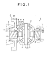
- FIG 1 is a schematic diagram illustrating a differential device according to a first embodiment of the invention.
- FIG 2 is an enlarged diagram illustrating a welded portion in the differential device depicted in FIG. 1 .
- FIGS. 3 and 4 are explanatory diagrams illustrating the operation of the differential device illustrated in FIG. 1 .
- FIG. 5 is an explanatory diagram illustrating an abutting portion and a welded portion in the differential device depicted in FIG. 1 .
- FIG. 6 is an explanatory diagram illustrating the differential device illustrated in FIG. 1 during flaw inspection.
- FIGS. 7 and 8 are explanatory diagrams illustrating modifications of the differential device illustrated in FIG. 1 .
- a differential device 1 which is used, for instance, in a vehicle such as an automobile, has the function of transmitting power generated by an engine to a drive shaft.
- the differential device 1 is provided with a differential case 2, a ring gear (differential ring) 3, pinions 4, side gears 5, a pinion shaft 6, and a housing 7 that holds the foregoing ( FIG. 1 ).
- the differential case 2 is a case that holds a gear group (pinions 4 and side gears 5).
- the differential case 2 is supported at both end portions 22, 23 thereof in the housing 7, by way of a pair of bearings 81, 82, so that the differential case 2 can rotate about a drive shaft.
- the drive shaft runs through a tubular hole 10, provided at the inner periphery of both end portions 22, 23 of the differential case 2.
- the drive shaft is connected to the side gears 5.
- the bearings 81, 82 are made up of taper bearings but are not limited thereto, and may be made up of ball bearings.
- the ring gear 3 is assembled with and coupled to the differential case 2, and rotates together with the differential case 2 about the drive shaft.
- the ring gear 3 meshes with an engine-side drive pinion (not shown).
- the coupling structure of the ring gear 3 and the differential case 2 is described further below.
- the pinions 4 and the side gears 5 are housed in the differential case 2 and are disposed meshing with each other.
- the pinions 4 can rotate about the pinion shaft 6 relative to the latter, and the differential case 2 and the pinions 4 can rotate together about the drive shaft.
- the side gears 5 are fitted and fixed to the drive shaft, and rotate integrally with the latter.
- the power generated by the engine is transmitted to the ring gear 3, and the ring gear 3 and the differential case 2 rotate together about the drive shaft.
- the pinions 4 rotate together with the differential case 2.
- the rotation of the pinions 4 is transmitted to the drive shaft via the side gears 5.
- the drive shaft rotates on account of power from the engine that is transmitted to the drive shaft.
- the differential case 2 and the ring gear 3 are coupled by way of the below-described coupling structure ( FIGS. 1 and 2 ).
- the differential case 2 has a main body portion 21 that houses a gear group (pinions 4 and side gears 5), and tubular end portions 22, 23 that extend along the drive shaft from both ends of the main body portion 21.
- the ring gear 3 is made up of a helical gear having a ring-like structure.
- the ring gear 3 has a gear portion 31 on the outer periphery, and a fitting portion 32 on the inner periphery.
- the ring gear 3 is assembled onto the differential case 2 through press-fitting of the fitting portion 32 of the ring gear 3 to one end portion 22 of the differential case 2.
- the ring gear 3 is positioned through abutting of the fitting portion 32 of the ring gear 3 and the main body portion 21 of the differential case 2.
- the gear portion 31 of the ring gear 3 meshes with the engine-side drive pinion.
- the bearing 81 is press-fitted to the end portion 22 of the differential case 2.
- the fitting portion 32 of the ring gear 3 is held wedged between the inner race of the bearing 81 and the main body portion 21 of the differential case 2.
- the outer race of the bearing 81 is held on the housing 7, whereby the bearing 81 is fixed.
- the fitting portion 32 of the ring gear 3 and the main body portion 21 of the differential case 2 axe welded to each other at the abutting portion ( FIG. 2 ).
- the fitting portion 32 of the ring gear 3 is fitted to the outer periphery of one end portion 22 of the differential case 2, in the axial direction of the drive shaft.
- the ring gear 3 abuts the main body portion 21 of the differential case 2, in the axial direction of the drive shaft.
- the ring gear 3 and the main body portion 21 of the differential case 2 are welded to each other at an abutting portion 33 in the axial direction of the drive shaft (welded portion W).
- the ring gear 3 and the differential case 2 are integrally fixed to each other as a result.
- the welded portion W is formed by laser welding, but may be formed by any other welding method. Welding is carried out in the outer peripheral direction of the ring gear 3.
- a thrust load (helical gear-specific thrust load), derived from the helical angle of the helical gear, acts on the ring gear 3 ( FIGS. 3 and 4 ) during engine operation.
- damage to the welded portion W can be suppressed thanks to the above-described position of the welded portion W between the ring gear 3 and the differential case 2.
- the ring gear 3 of the differential device 1 has a helical gear, as explained above, the ring gear 3 abuts the differential case 2 in the axial direction of the drive shaft, and the ring gear 3 and the differential case 2 are welded to each other at the abutting portion 33 of the ring gear 3 and the differential case 2, in the axial direction of the drive shaft ( FIG. 2 ).
- thrust bending stress is less likely to occur at the position of the welded portion W when a thrust load Pth acts on the ring gear 3 in the direction towards the abutting portion 33 with the differential case 2 (direction towards the main body portion 21 of the differential case 2), in the axial direction of the drive shaft, as illustrated in FIG. 3 .
- the strength of the welded portion W is secured, and damage (for instance; weld detachment) of the welded portion W is suppressed, which is advantageous.
- This makes it unnecessary to increase wall thickness (wall thickness of the ring gear and the differential case) for preserving the strength of the welded portion W. Therefore, the device can be made lighter, which is likewise advantageous. In such a configuration, moreover, the weld penetration depth at the welded portion W can be made shallower, and hence the cost of the welding equipment can be reduced, which is advantageous.
- the differential case 2 has a main body portion 21 that houses the gear group 4, 5, and end portions 22, 23 that extend from both ends of the main body portion 21 along the drive shaft ( FIGS. 1 and 2 ).
- the ring gear 3 is disposed fitted to the outer periphery of one end portion 22 of the differential case 2.
- the ring gear 3 abuts herein the main body portion 21 of the differential case 2 in the axial direction of the drive shaft.
- the ring gear 3 and the main body portion 21 of the differential case 2 are welded to each other at the abutting portion 33, in the axial direction of the drive shaft.
- the bearing 81 is disposed abutting the ring gear 3 in the axial direction of the drive shaft, so that the ring gear 3 is wedged between the bearing 81 and the differential case 2 ( FIG. 2 ).
- thrust bending stress is less likely to occur at the position of the welded portion W when a thrust load Pth acts on the ring gear 3, in the direction towards the abutting portion 34 with the bearing 81 (direction towards the end portion 22 of the differential case 2), in the axial direction of the drive shaft, as illustrated in FIG. 4 .
- the strength of the welded portion W is secured as a result, which is advantageous.
- the position in the radial direction of the drive shaft is called the radial direction position.
- the differential device 1 satisfies a relationship Rw ⁇ Rx, wherein Rw is the distance from the shaft center of the drive shaft up to the radial direction position of the welded portion W between the ring gear 3 and the differential case 2, and Rx is the distance from the shaft center of the drive shaft up to the radial direction position of the abutting portion 34 of the ring gear 3 and the bearing 81 ( FIG. 5 ).
- the radial direction position Rw of the welded portion W is optimized relative to the radial direction position Rx of the abutting portion 34 of the ring gear 3 and the bearing 81.
- the fitting portion 32 of the ring gear 3 and the main body portion 21 of the differential case 2 are welded to each other at the abutting portion 33.
- the fitting portion 32 of the ring gear 3 is held wedged between the inner race of the bearing 81 and the main body portion 21 of the differential case 2, in the axial direction of the drive shaft ( FIG. 2 ).
- the distance Rw from the shaft center of the drive shaft up to the radial direction position of the welded portion W at the inward end of the welded portion W in the radial direction is positioned further inward, in the radial direction of the drive shaft, than the distance Rx from the shaft center of the drive shaft up to the radial direction position of the abutting portion 34 of the ring gear 3 and the bearing 81, at the outward end of the abutting portion 34 in the radial direction.
- the strength of the welded portion W is secured thereby
- the relationship between the distance Rw from the shaft center of the drive shaft to the radial direction position of the welded portion W and the distance Rx from the shaft center of the drive shaft up to the radial direction position of the abutting portion 34 is set in accordance with the thrust bending stress that acts in the direction in which the welded portion W is stripped off when under load.
- a flat finishing is applied to the face of the ring gear 3 that is positioned on the opposite side to the welded portion W between the ring gear 3 and the differential case 2, from among both faces (front and rear face) of the ring gear 3 that are positioned in the axial direction of the drive shaft. That is, the ring gear 3 abuts against and is welded to the differential case 2 at one of the two faces that are positioned in the axial direction of the drive shaft, while the other face is subjected to flattening.
- the welded portion W between the ring gear 3 and the differential case 2 is tested for faults (for instance, by ultrasonic testing) using a test probe P, during manufacture of the differential device 1, or during maintenance later on.
- the ring gear 3 has a ring-like structure in which the fitting portion 32 is formed in the inner periphery of the ring ( FIGS. 2 and 6 ).
- the fitting portion 32 is positioned by being press-fitted to the end portion 22 of the differential case 2, and by abutting the main body portion 21 of the differential case 2, in the axial direction of the drive shaft.
- the fitting portion 32 is welded to the main body portion 21 of the differential case 2, as a result of which the ring gear 3 is fixed to the differential case 2.
- the flat finishing is carried out by mechanical working of the cast ring gear 3.
- the ring gear 3 and the differential case 2 are welded together around an entire circumference of the ring gear 3.
- the entire circumference of the fitting portion 32 is flattened in accordance with the welded area.
- the inner race of the bearing 81 abuts the face of the fitting portion 32 that has been flattened, in the axial direction of the drive shaft.
- the bearing 81 is disposed herein so that the ring gear 3 is wedged between the differential case 2 and the bearing 81 ( FIG 2 ).
- flattening of the fitting portion 32 has the effect of securing an appropriate abutting face with the inner race of the bearing 81.
- the pinion shaft 6 is disposed in the differential case 2 of the differential device 1, as illustrated in FIGS. 7 and 8 .
- the pinion shaft 6 which is inserted into the shaft insertion hole 25 provided in the differential case 2, couples the differential case 2 to the pinions 4.
- the pinions 4 and the differential case 2 rotate together as a result.
- the pinion shaft 6 is fixed to the differential case 2 by way of a fixing pin 9.
- the fixing pin 9 is inserted into the pinion shaft 6 through a pin insertion hole 26 provided in the differential case 2.
- the pinion shaft 6 is prevented thereby from coming off the shaft insertion hole 25.
- the ring gear 3 is disposed so as to obstruct the inlet portion of the pin insertion hole 26 ( FIGS. 7 and 8 ).
- the fixing pin 9 is prevented thereby from coming off the pin insertion hole 26, and thus the reliability of the device is enhanced, which is advantageous.
- the fixing pin requires no crimping or the like.
- the pin insertion hole 26 is opened in the main body portion 21 of the differential case 2.
- the pin insertion hole 26 is opened on the side of the ring gear 3, in the axial direction of the drive shaft ( FIGS. 7 and 8 ) The far end of the pin insertion hole 26 is blocked.
- the fitting portion 32 of the ring gear 3 abuts against, and is welded to, the main body portion 21 of the Differential case 2, so that the fitting portion 32 of the ring gear 3 blocks the pin insertion hole 26 at the position of the welded portion W. That is, the welded portion W and the inlet portion of the pin insertion hole 26 are disposed at substantially the same position.
- Such a configuration is advantageous in that it allows gases generated during welding to escape into the pin insertion hole 26. The likelihood of failure of the welded portion W is reduced as a result.
- FIG. 9 is a schematic diagram illustrating a differential device according to a second embodiment of the invention.
- FIGS. 10 and 11 are explanatory diagrams illustrating the operation of the differential device illustrated in FIG. 9 .
- FIG. 12 is an explanatory diagram illustrating a modification of the differential device illustrated in FIG. 9 .
- constituent elements identical to those of the first embodiment are denoted with the same reference numerals, and a recurrent explanation thereof will be omitted.
- the differential device 1 of the second embodiment has the following differences vis-à-vis the differential device 1 of the first embodiment ( FIG. 9 ).
- the differential case 2 has a flange portion 24.
- the flange portion 24 extends ring-like around the outer periphery of the main body portion 21, about the drive shaft.
- the outer peripheral edge of the flange portion 24 has a stepped shape (inlay shape).
- the ring gear 3 is assembled into the differential case 2 through press fitting of the fitting portion 32 of the ring gear 3 against the outer periphery of the flange portion 24 of the differential case 2.
- the ring gear 3 and the flange portion 24 are welded together at a fitting face 35 of the ring gear 3 and the flange portion 24.
- the ring gear 3 is positioned through abutting of the fitting portion 32 of the ring gear 3 against the flange portion 24 of the differential case 2.
- the bearing 81 is press-fitted against the inner periphery of the gear portion 31 of the ring gear 3.
- the ring gear 3 is held wedged between the outer race of the bearing 81 and the flange portion 24 of the differential case 2.
- the inner race of the bearing 81 is held on the housing 7, whereby the bearing 81 is fixed.
- the ring gear 3 and the differential case 2 are supported on two sides within the housing 7, by way of the pair of bearings 81, 82, so that the ring gear 3 and the differential case 2 are disposed rotatably about the drive shaft.
- a thrust load (helical gear-specific thrust load), derived from the helical angle of the helical gear, acts on the ring gear 3 of the differential device 1 ( FIGS. 10 and 11 ).
- the ring gear 3 abuts the flange portion 24 of the differential case 2, in the axial direction of the drive shaft, and the ring gear 3 and the flange portion 24 are welded to each other at the fitting face 35 between the ring gear 3 and the flange portion 24. Damage to the welded portion W is suppressed thereby.
- the ring gear 3 abuts the differential case 2 in the axial direction of the drive shaft.
- the ring gear 3 and the differential case 2 are welded together at the fitting face 35 ( FIG. 9 ).
- thrust bending stress or shear stress
- the ring gear 3 is less likely to occur at the position of the welded portion W when a thrust load Pth acts on the ring gear 3 in the direction towards the abutting portion 33 with the differential case 2 (direction towards the main body portion 21 of the differential case 2), in the axial direction of the drive shaft, as illustrated in FIG. 10 .
- the strength of the welded portion W is secured as a result, so that damage to the welded portion W (for instance, weld detachment) is suppressed, which is advantageous.
- damage to the welded portion W for instance, weld detachment
- the flange portion 24 of the differential case 2 has a stepped shape with a large diameter at the far end in the direction in which the ring gear 3 is assembled (direction from left to right in FIG 9 ), as viewed from the cross section of the differential case 2 in the radial direction.
- the fitting portion 32 of the ring gear 3 abuts the large-diameter portion of the flange portion 24 in the axial direction of the drive shaft.
- the ring gear 3 and the flange portion 24 of the differential case 2 are welded together at the fitting face 35. As a result, the position of the welded portion W between the ring gear 3 and the differential case 2 is optimized, and the strength of the welded portion W is secured.
- the bearing 81 is disposed abutting the ring gear 3 in the axial direction of the drive shaft, so that the ring gear 3 is wedged between the bearing 81 and the differential case 2 ( FIG. 9 ).
- thrust bending stress is less likely to occur at the position of the welded portion W when a thrust load Pth acts on the ring gear 3 in the direction towards the abutting portion 34 with the bearing 81 (direction towards the end portion 22 of the differential case 2), in the axial direction of the drive shaft, ( FIG. 11 ).
- the strength of the welded portion W is secured thereby, which is advantageous.
- the differential device 1 satisfies a relationship Rw ⁇ Rx, wherein Rw is the distance from the shaft center of the drive shaft up to the radial direction position of the welded portion W between the ring gear 3 and the differential case 2, and Rx is the distance from the shaft center of the drive shaft up to the radial direction position of the abutting portion 34 of the ring gear 3 and the bearing 81 ( FIG. 12 ).
- Rw is the distance from the shaft center of the drive shaft up to the radial direction position of the welded portion W between the ring gear 3 and the differential case 2
- Rx is the distance from the shaft center of the drive shaft up to the radial direction position of the abutting portion 34 of the ring gear 3 and the bearing 81 ( FIG. 12 ).
- the distance Rw from the shaft center of the drive shaft to the radial direction position of the welded portion W is optimized relative to the distance Rx from the shaft center of the drive shaft up to the radial direction position of the abutting portion 34 of
- the fitting portion 32 of the ring gear 3 and the flange portion 24 of the differential case 2 are welded to each other at the fitting face 35.
- the fitting portion 32 of the ring gear 3 is held wedged, in the axial direction of the drive shaft, between the inner race of the bearing 81 and the flange portion 24 of the differential case 2 ( FIG. 9 ).
- the distance Rw from the shaft center of the drive shaft up to the radial direction position, in the radial direction, at the central portion of the welded portion W is positioned further inward, in the radial direction of the drive shaft, than the distance Rx from the shaft center of the drive shaft up to the radial direction position at the outward end of the abutting portion 34 of the ring gear 3 and the bearing 81 in the radial direction.
- the strength of the welded portion W is secured thereby.
- the relationship between the distance Rw from the shaft center of the drive shaft up to the radial direction position of the welded portion W and the distance Rx from the shaft center of the drive shaft up to the radial direction position of the abutting portion 34 is set in accordance with the thrust bending stress or shear stress that acts in the direction in which the welded portion W is stripped off when under load.
- the differential device according to the invention is useful as it allows effectively suppressing damage of the welded portion between the differential case and the ring gear.
- a differential device comprising a differential case (2) that houses a gear group (4, 5), and a ring gear (3) disposed fitted to the differential case (2), such that the differential case (2) and the ring gear (3) being supported rotatably about a drive shaft, characterized in that the ring gear (3) is formed by a helical gear, the ring gear (3) abuts the differential case (2) in an axial direction of the drive shaft, and the ring gear (3) and the differential case (2) are welded at an abutting portion (33) of the ring gear (3) and the differential case (2) in the axial direction of the drive shaft.
- Item 2 The differential device according to item 1, characterized in that the differential case (2) has a main body portion (21) that holds the gear group (4, 5), and end portions (22, 23) that extend along the drive shaft from the main body portion (21); the ring gear (3) is disposed fitted to an outer periphery of the end portion (22); the ring gear (3) abuts the main, body portion (21) in the axial direction of the drive shaft; and the ring gear (3) and the main body portion (21) are welded at the abutting portion (33) of the ring gear (3) and the differential case (2) in the axial direction of the drive shaft.
- Item 3 The differential device according to item 1 or 2, characterized in that a flat finishing is applied to a face of the ring gear (3), the face being positioned on an opposite side to a welded portion (W) between the ring gear (3) and the differential case (2), from among both faces of the ring gear (3) that are positioned in the axial direction of the drive shaft.
- Item 4 The differential device according to any one of items 1 through 3, characterized by further comprising: a pinion shaft (6) that is disposed inside the differential case (2) and that couples the differential case (2); and the gear group (4, 5); and a fixing pin (9) that is inserted into a pin insertion hole (26) provided in the differential case (2) and that fixes the pinion shaft (6), wherein the ring gear (3) blocks an inlet portion of the pin insertion hole (26).
- Item 5 The differential device according to item 4, characterized in that the ring gear (3) and the differential case (2) are welded at a position where the ring gear (3) blocks the inlet portion of the pin insertion hole (26).
- Item 6 The differential device according to any one of items 1 through 5, characterized by further comprising: a bearing (81) that abuts the ring gear (3) in the axial direction, of the drive shaft, such that the ring gear (3) is wedged between the bearing (81) and the differential case (2).
- Item 7 The differential device according to item 6, characterized in that a relationship Rw ⁇ Rx is satisfied, wherein Rw is a distance from a shaft center of the drive shaft up to a radial direction position of a welded portion (W) between the ring gear (3) and the differential case (2), and Rx is a distance from the shaft center of the drive shaft up to a radial direction position of an abutting portion (34) of the ring gear (3) and the bearing (81), where the radial direction position designates the position in the radial direction of the drive shaft.
- Rw is a distance from a shaft center of the drive shaft up to a radial direction position of a welded portion (W) between the ring gear (3) and the differential case (2)
- Rx is a distance from the shaft center of the drive shaft up to a radial direction position of an abutting portion (34) of the ring gear (3) and the bearing (81), where the radial direction position designates the position in the radial direction of the drive shaft.
- Item 8 The differential device according to item 7, characterized in that the radial direction position of the welded portion (W) of the ring gear (3) and the differential case (2) is a position of the welded portion (W)5 the position being closest to the shaft center in the radial direction; and the radial direction position of the abutting portion (34) of the ring gear (3) and the bearing (81) is aposition of the bearing (81), the position being furthest from the shaft center.
- a differential device comprising a differential case (2) that houses a gear group (4, 5), and a ring gear (3) disposed fitted to the differential case (2), the differential case (2) and the ring gear (3) being supported rotatably about a drive shaft, characterized in that the ring gear (3) is formed by a helical gear having a ring-like structure, the ring gear (3) abuts the differential case (2) in an axial direction of the drive shaft, and the ring gear (3) and the differential case (2) are welded to each other at a fitting face (35).
- Item 10 The differential device according to item 9, characterized in that the differential case (2) has a flange portion (24) having a stepped shape, when the ring gear (3) is disposed fitted to the flange portion (24), the ring gear (3) abuts the flange portion (24) in the axial direction of the drive shaft, and the ring gear (3) and the flange portion (24) are welded at the fitting face (35) of the ring gear (3) and the flange portion (24).
- Item 11 The differential device according to item 9 or 10, characterized by further comprising: a beating (81) that abuts the ring gear (3) in the axial direction of the drive shaft, such that the ring gear (3) is wedged between the bearing (81) and the differential case (2).
- Item 12 The differential device according to item 11, characterized in that a relationship Rw ⁇ Rx is satisfied, wherein Rw is a distance from a shaft center of the drive shaft up to a radial direction position of a welded portion (W) between the ring gear (3) and the differential case (2), and Rx is a distance from the shaft center of the drive shaft up to a radial direction position of an abutting portion (34) of the ring gear (3) and the bearing (81), where the radial direction position designates the position in the radial direction of the drive shaft.
- Rw is a distance from a shaft center of the drive shaft up to a radial direction position of a welded portion (W) between the ring gear (3) and the differential case (2)
- Rx is a distance from the shaft center of the drive shaft up to a radial direction position of an abutting portion (34) of the ring gear (3) and the bearing (81), where the radial direction position designates the position in the radial direction of the drive shaft.
- Item 13 The differential device according to item 12, characterized in that the position of the welded portion (W) of the ring gear (3) and the differential case (2) in the radial direction is a position of a central portion of the welded portion (W) in the radial direction, and the radial direction position of the abutting portion (34) of the ring gear (3) and the bearing (81) is a position of the bearing (81), the position being furthest from the shaft center.
Landscapes
- Engineering & Computer Science (AREA)
- General Engineering & Computer Science (AREA)
- Mechanical Engineering (AREA)
- Retarders (AREA)
- General Details Of Gearings (AREA)
- Motor Power Transmission Devices (AREA)
Abstract
Description
- The invention relates to a differential device, and more particularly, to a differential device that effectively allows suppressing damage to a welded portion between a differential case and a ring gear.
- A differential device has ordinarily a differential case that houses a gear group, and a ring gear that is disposed fitted to the Differential case. The differential case and the ring gear are supported rotatably about a drive shaft. Integral welding of the differential case and the ring gear is a recent trend. Japanese Patent Application Publication No.
2007-192326 JP-A-2007-192326 - Another recent trend is the use of ring gears that have a helical gear. In such a configuration, a thrust load (helical gear-specific thrust load), derived from the helical angle of the helical gear, acts on the ring gear. Thrust load may damage the welded portion of the differential case and the ring gear (for instance, weld detachment).
- In the light of the above, therefore, it is an object of the invention to provide a differential device that allows effectively suppressing damage of a welded portion between a differential case and a ring gear.
- In one aspect of the invention there is provided a differential device that has a differential case that houses a gear group, and a ring gear disposed fitted to the differential case, the differential case and the ring gear being supported rotatably about a drive shaft, wherein the ring gear is formed by a helical gear, the ring gear abuts the differential case in the axial direction of the drive shaft, and the ring gear and the differential case are welded at an abutting portion of the ring gear and the differential case in the axial direction of the drive shaft.
- When the ring gear has a helical gear in such a differential device, the ring gear abuts the differential case in the axial direction of the drive shaft, and the ring gear and the differential case are welded at an abutting portion of the ring gear and the differential case in the axial direction of the drive shaft. In such a configuration, thrust bending stress is less likely to occur at.the position of the welded portion when a thrust load acts on the ring gear, in the direction towards the abutting portion with the differential case, in the axial direction of the drive shaft. The strength of the welded portion is secured as a result, and damage to the welded portion (for instance, weld detachment) is suppressed, which is advantageous.
- In the differential device according to the invention, preferably, the differential case has a main body portion that holds the gear group, and end portions that extend along the drive shaft from the main body portion; the ring gear is disposed fitted to the outer periphery of the end portion; the ring gear abuts the main body portion in the axial direction of the drive shaft; and the ring gear and the differential case are welded at an abutting portion of the ring gear and the differential case, in the axial direction of the drive shaft.
- Such a differential device is advantageous in that the position of the welded portion of the ring gear and the differential case is optimized, whereby the strength of the welded portion is secured.
- In the differential device according to the invention, a flat finishing may suitably be applied to the face of the ring gear, the face being positioned on the opposite side to a welded portion between the ring gear and the differential case, from among both faces of the ring gear that are positioned in the axial direction of the drive shaft.
- In such a differential device, an adequate pressing surface is secured for a test probe, since a flat finishing is applied to the face of the ring gear that is positioned on the opposite side to a welded portion between the ring gear and the differential case, from among both faces of the ring gear. Testing of the welded portion is thus carried out appropriately, which is advantageous.
- The differential device according to the invention may suitably have a pinion shaft that is disposed inside the differential case and that couples the differential case and the gear group; and a fixing pin that is inserted into a pin insertion hole provided in the differential case and that fixes the pinion shaft; wherein the ring gear blocks an inlet portion of the pin insertion hole.
- Such a differential device is advantageous in that the fixing pin is prevented from coming off the pin insertion hole, whereby the reliability of the device is enhanced.
- In the differential device according to the invention, the ring gear and the differential case may be appropriately welded at a position where the ring gear blocks the inlet portion of the pin insertion hole.
- Such a differential device is advantageous in that gas generated during welding can escape into the pin insertion hole. This reduces the likelihood of welded portion failure.
- In another aspect of the invention there is provided a differential device that has a differential case that houses a gear group, and a ring gear disposed fitted to the differential device, such that the differential case and the ring gear are supported rotatably about a drive shaft, and wherein the ring gear has a helical gear having a ring-like structure, the ring gear abuts the differential case, in the axial direction of the drive shaft, and the ring gear and the differential case are welded to each other at a fitting face.
- In such a differential device, the ring gear abuts the differential case in the axial direction of the drive shaft, and the ring gear and the differential case are welded to each other at a fitting face. In such a configuration, thrust bending stress is less likely to occur at the position of the welded portion when a thrust load acts on the ring gear in the direction towards the abutting portion with the differential case, in the axial direction of the drive shaft. The strength of the welded portion is secured thereby, so that damage of the welded portion (for instance, weld detachment) is suppressed, which is advantageous.
- In the differential device according to the invention, the differential case may suitably have a flange portion having a stepped shape, wherein when the ring gear is disposed fitted to the flange portion, the ring gear abuts the flange portion in the axial direction of the drive shaft, and the ring gear and the flange portion are welded at the fitting face of the ring gear and the flange portion.
- In such a differential device, the position of the welded portion of the ring gear and the differential case is optimized, and the strength of the welded portion is secured.
- The differential device according to the invention may suitably have a bearing that abuts the ring gear in the axial direction of the drive shaft, such that the ring gear is wedged between the bearing and the differential case.
- In such a differential device, thrust bending stress is less likely to occur at the position of the welded portion when a thrust load acts on the ring gear in the direction towards the abutting portion with the bearing, in the axial direction of the drive shaft. The strength of the welded portion is secured as a result, which is advantageous.
- The differential device according to the invention satisfies a relationship Rw < Rx, wherein Rw is the distance from the shaft center of the drive shaft up to a radial direction position of a welded portion between the ring gear and the differential case, and Rx is the distance from the shaft center of the drive shaft up to a radial direction position of an abutting portion of the ring gear and the bearing, where the radial direction position designates the position in the radial direction of the drive shaft,
- In such a differential device, the distance Rw from the shaft center of the drive shaft to the radial direction position of the welded portion is optimized relative to the distance Rx from the shaft center of the drive shaft up to the radial direction position of the abutting portion of the bearing and the ring gear. Therefore, when a thrust load acts on the ring gear in the direction towards the abutting portion with the bearing, in the axial direction of the drive shaft, the thrust load is supported further outwards in the radial direction of the ring gear than the distance Rw from the shaft center of the drive shaft up to the radial direction position of the welded portion. Occurrence of thrust bending stress in the welded portion is suppressed thereby, so that the strength of the welded portion is secured, which is advantageous.
- When in the differential device according to the invention the ring gear is a helical gear, the ring gear abuts the differential case in the axial direction of the drive shaft, and the ring gear and the differential case are welded at an abutting portion of the ring gear and the differential case, in the axial direction of the drive shaft. In such a configuration, thrust bending stress is less likely to occur at the welded portion when a thrust load acts on the ring gear in the direction towards the abutting portion with the Differential case, in the axial direction of the drive shaft. The strength of the welded portion is secured as a result, and damage to the welded portion (for instance, weld detachment) is suppressed, which is advantageous.
- The features, advantages, and technical and industrial significance of this invention will be described in the following detailed description of example embodiment of the invention with reference to the accompanying drawings, in which like numerals denote like elements, and wherein:
-
FIG. 1 is a schematic diagram illustrating a differential device according to a first embodiment of the invention; -
FIG. 2 is an enlarged diagram illustrating a welded portion in the differential device depicted inFIG. 1 ; -
FIG 3 is an explanatory diagram illustrating the operation of the differential device illustrated inFIG. 1 ; -
FIG. 4 is an explanatory diagram illustrating the operation of the differential device illustrated inFIG. 1 ; -
FIG. 5 is an explanatory diagram illustrating an abutting portion and a welded portion in the differential device depicted inFIG. 1 ; -
FIG. 6 is an explanatory diagram illustrating the differential device illustrated inFIG. 1 during flaw inspection; -
FIG. 7 is an explanatory diagram illustrating a modification of the differential device illustrated inFIG. 1 ; -
FIG. 8 is an explanatory diagram illustrating a modification of the differential device illustrated inFIG. 1 ; -
FIG. 9 is a schematic diagram illustrating a differential device according to a second embodiment of the invention; -
FIG 10 is an explanatory diagram illustrating the operation of the differential device illustrated inFIG. 9 ; -
FIG 11 is an explanatory diagram illustrating the operation of the differential device illustrated inFIG. 9 ; and -
FIG. 12 is an explanatory diagram illustrating a modification of the differential device illustrated inFIG. 9 . - Embodiments of the invention are explained next in detail with reference to accompanying drawings. The invention, however, is not limited by the embodiments. The constituent elements include constituent elements that can be substituted, in obvious ways, while preserving the identity of the invention. Moreover, the various modifications set forth in the embodiments can be appropriately combined in ways that would be evident to a person skilled in the art.
- A first embodiment of the invention will be explained first.
FIG 1 is a schematic diagram illustrating a differential device according to a first embodiment of the invention.FIG 2 is an enlarged diagram illustrating a welded portion in the differential device depicted inFIG. 1 .FIGS. 3 and 4 are explanatory diagrams illustrating the operation of the differential device illustrated inFIG. 1 .FIG. 5 is an explanatory diagram illustrating an abutting portion and a welded portion in the differential device depicted inFIG. 1 .FIG. 6 is an explanatory diagram illustrating the differential device illustrated inFIG. 1 during flaw inspection.FIGS. 7 and 8 are explanatory diagrams illustrating modifications of the differential device illustrated inFIG. 1 . - A
differential device 1, which is used, for instance, in a vehicle such as an automobile, has the function of transmitting power generated by an engine to a drive shaft. Thedifferential device 1 is provided with adifferential case 2, a ring gear (differential ring) 3, pinions 4, side gears 5, apinion shaft 6, and ahousing 7 that holds the foregoing (FIG. 1 ). - The
differential case 2 is a case that holds a gear group (pinions 4 and side gears 5). Thedifferential case 2 is supported at bothend portions housing 7, by way of a pair ofbearings differential case 2 can rotate about a drive shaft. The drive shaft runs through atubular hole 10, provided at the inner periphery of bothend portions differential case 2. The drive shaft is connected to the side gears 5. In the first embodiment, thebearings ring gear 3 is assembled with and coupled to thedifferential case 2, and rotates together with thedifferential case 2 about the drive shaft. Thering gear 3 meshes with an engine-side drive pinion (not shown). The coupling structure of thering gear 3 and thedifferential case 2 is described further below. Thepinions 4 and the side gears 5 are housed in thedifferential case 2 and are disposed meshing with each other. Thepinion shaft 6, which is inserted into ashaft insertion hole 25 provided in thedifferential case 2, couples thedifferential case 2 to thepinions 4. As a result, thepinions 4 can rotate about thepinion shaft 6 relative to the latter, and thedifferential case 2 and thepinions 4 can rotate together about the drive shaft. The side gears 5 are fitted and fixed to the drive shaft, and rotate integrally with the latter. - In the
differential device 1, firstly, the power generated by the engine is transmitted to thering gear 3, and thering gear 3 and thedifferential case 2 rotate together about the drive shaft. Thereupon, thepinions 4 rotate together with thedifferential case 2. The rotation of thepinions 4 is transmitted to the drive shaft via the side gears 5. As a result, the drive shaft rotates on account of power from the engine that is transmitted to the drive shaft. - In the first embodiment, the
differential case 2 and thering gear 3 are coupled by way of the below-described coupling structure (FIGS. 1 and2 ). Firstly, thedifferential case 2 has amain body portion 21 that houses a gear group (pinions 4 and side gears 5), andtubular end portions main body portion 21. Thering gear 3 is made up of a helical gear having a ring-like structure. Thering gear 3 has agear portion 31 on the outer periphery, and afitting portion 32 on the inner periphery. Thering gear 3 is assembled onto thedifferential case 2 through press-fitting of thefitting portion 32 of thering gear 3 to oneend portion 22 of thedifferential case 2. Thering gear 3 is positioned through abutting of thefitting portion 32 of thering gear 3 and themain body portion 21 of thedifferential case 2. Thegear portion 31 of thering gear 3 meshes with the engine-side drive pinion. Thebearing 81 is press-fitted to theend portion 22 of thedifferential case 2. Thefitting portion 32 of thering gear 3 is held wedged between the inner race of thebearing 81 and themain body portion 21 of thedifferential case 2. The outer race of thebearing 81 is held on thehousing 7, whereby thebearing 81 is fixed. - The
fitting portion 32 of thering gear 3 and themain body portion 21 of thedifferential case 2 axe welded to each other at the abutting portion (FIG. 2 ). In the first embodiment, for instance, thefitting portion 32 of thering gear 3 is fitted to the outer periphery of oneend portion 22 of thedifferential case 2, in the axial direction of the drive shaft. When assembled, thering gear 3 abuts themain body portion 21 of thedifferential case 2, in the axial direction of the drive shaft. Thering gear 3 and themain body portion 21 of thedifferential case 2 are welded to each other at an abuttingportion 33 in the axial direction of the drive shaft (welded portion W). Thering gear 3 and thedifferential case 2 are integrally fixed to each other as a result. Preferably, the welded portion W is formed by laser welding, but may be formed by any other welding method. Welding is carried out in the outer peripheral direction of thering gear 3. - In the
differential device 1, a thrust load (helical gear-specific thrust load), derived from the helical angle of the helical gear, acts on the ring gear 3 (FIGS. 3 and 4 ) during engine operation. Herein, damage to the welded portion W can be suppressed thanks to the above-described position of the welded portion W between thering gear 3 and thedifferential case 2. - For instance, (1) when a thrust load Pth acts on the
ring gear 3 in the direction towards themain body portion 21 of thedifferential case 2, in the axial direction of the drive shaft, a reaction force F1 from the bearing 82 on the opposite side acts on the ring gear 3 (FIG. 3 ). Themain body portion 21 of thedifferential case 2 supports here thefitting portion 32 of thering gear 3 in the axial direction of the drive shaft, and hence thrust bending stress is less likely to occur in the abuttingportion 33 of thefitting portion 32 of thering gear 3 and themain body portion 21 of thedifferential case 2. As a result, the welded portion W is less likely to suffer damage. - In addition, (2) when a thrust load Pth acts on the
ring gear 3 in the direction towardsend portion 22 of thedifferential case 2, in the axial direction of the drive shaft, a reaction force F2 from the bearing 81 on the same side acts on the ring gear 3 (FIG. 4 ). Thebearing 81 supports herein thefitting portion 32 of thering gear 3 in the axial direction of the drive shaft, and hence thrust bending stress is less likely to occur in the abuttingportion 34 between thefitting portion 32 of thering gear 3 and thebearing 81. As a result, the welded portion W is less likely to suffer damage. - When the
ring gear 3 of thedifferential device 1 has a helical gear, as explained above, thering gear 3 abuts thedifferential case 2 in the axial direction of the drive shaft, and thering gear 3 and thedifferential case 2 are welded to each other at the abuttingportion 33 of thering gear 3 and thedifferential case 2, in the axial direction of the drive shaft (FIG. 2 ). In such a configuration, thrust bending stress is less likely to occur at the position of the welded portion W when a thrust load Pth acts on thering gear 3 in the direction towards the abuttingportion 33 with the differential case 2 (direction towards themain body portion 21 of the differential case 2), in the axial direction of the drive shaft, as illustrated inFIG. 3 . As a result, the strength of the welded portion W is secured, and damage (for instance; weld detachment) of the welded portion W is suppressed, which is advantageous. This makes it unnecessary to increase wall thickness (wall thickness of the ring gear and the differential case) for preserving the strength of the welded portion W. Therefore, the device can be made lighter, which is likewise advantageous. In such a configuration, moreover, the weld penetration depth at the welded portion W can be made shallower, and hence the cost of the welding equipment can be reduced, which is advantageous. - In the
differential device 1, as described above, thedifferential case 2 has amain body portion 21 that houses thegear group portions main body portion 21 along the drive shaft (FIGS. 1 and2 ). Thering gear 3 is disposed fitted to the outer periphery of oneend portion 22 of thedifferential case 2. Thering gear 3 abuts herein themain body portion 21 of thedifferential case 2 in the axial direction of the drive shaft. Thering gear 3 and themain body portion 21 of thedifferential case 2 are welded to each other at the abuttingportion 33, in the axial direction of the drive shaft. As a result, the position of the welded portion W between thering gear 3 and thedifferential case 2 is optimized, and the strength of the welded portion W is secured. - In the
differential device 1, also, thebearing 81 is disposed abutting thering gear 3 in the axial direction of the drive shaft, so that thering gear 3 is wedged between the bearing 81 and the differential case 2 (FIG. 2 ). In such a configuration, thrust bending stress is less likely to occur at the position of the welded portion W when a thrust load Pth acts on thering gear 3, in the direction towards the abuttingportion 34 with the bearing 81 (direction towards theend portion 22 of the differential case 2), in the axial direction of the drive shaft, as illustrated inFIG. 4 . The strength of the welded portion W is secured as a result, which is advantageous. - The position in the radial direction of the drive shaft is called the radial direction position. Preferably, the
differential device 1 satisfies a relationship Rw < Rx, wherein Rw is the distance from the shaft center of the drive shaft up to the radial direction position of the welded portion W between thering gear 3 and thedifferential case 2, and Rx is the distance from the shaft center of the drive shaft up to the radial direction position of the abuttingportion 34 of thering gear 3 and the bearing 81 (FIG. 5 ). In such a configuration, the radial direction position Rw of the welded portion W is optimized relative to the radial direction position Rx of the abuttingportion 34 of thering gear 3 and thebearing 81. Therefore, when a thrust load Pth acts on thering gear 3 in a direction towards the abutting portion with thebearing 81, in the axial direction of the drive shaft, the thrust load Pth is supported by thering gear 3 further outwards in the radial direction than the radial direction position Rw of the welded portion W (FIG. 4 ). Occurrence of thrust bending stress in the welded portion W is suppressed thereby, so that the strength of the welded portion W is secured, which is advantageous. - In the first embodiment, as described above, the
fitting portion 32 of thering gear 3 and themain body portion 21 of thedifferential case 2 are welded to each other at the abuttingportion 33. Thefitting portion 32 of thering gear 3 is held wedged between the inner race of thebearing 81 and themain body portion 21 of thedifferential case 2, in the axial direction of the drive shaft (FIG. 2 ). Herein, the distance Rw from the shaft center of the drive shaft up to the radial direction position of the welded portion W at the inward end of the welded portion W in the radial direction is positioned further inward, in the radial direction of the drive shaft, than the distance Rx from the shaft center of the drive shaft up to the radial direction position of the abuttingportion 34 of thering gear 3 and thebearing 81, at the outward end of the abuttingportion 34 in the radial direction. The strength of the welded portion W is secured thereby The relationship between the distance Rw from the shaft center of the drive shaft to the radial direction position of the welded portion W and the distance Rx from the shaft center of the drive shaft up to the radial direction position of the abuttingportion 34 is set in accordance with the thrust bending stress that acts in the direction in which the welded portion W is stripped off when under load. - In the
differential device 1, preferably, a flat finishing is applied to the face of thering gear 3 that is positioned on the opposite side to the welded portion W between thering gear 3 and thedifferential case 2, from among both faces (front and rear face) of thering gear 3 that are positioned in the axial direction of the drive shaft. That is, thering gear 3 abuts against and is welded to thedifferential case 2 at one of the two faces that are positioned in the axial direction of the drive shaft, while the other face is subjected to flattening. The welded portion W between thering gear 3 and thedifferential case 2 is tested for faults (for instance, by ultrasonic testing) using a test probe P, during manufacture of thedifferential device 1, or during maintenance later on. An adequate pressing surface is secured for the test probe P, since the face of thering gear 3 that is positioned on the opposite side to the welded portion W welded to thedifferential case 2, from among the two faces of thering gear 3, is subjected to flattening. Testing of the welded portion W is thus carried out appropriately, which is advantageous. When the side face of thedifferential case 2 has, for instance, ribs (not shown), the above configuration is advantageous in that testing of the welded portion W can be performed easily over the entire circumference of thering gear 3, without interference by the ribs. - In the first embodiment, for instance, the
ring gear 3 has a ring-like structure in which thefitting portion 32 is formed in the inner periphery of the ring (FIGS. 2 and6 ). Thefitting portion 32 is positioned by being press-fitted to theend portion 22 of thedifferential case 2, and by abutting themain body portion 21 of thedifferential case 2, in the axial direction of the drive shaft. Thefitting portion 32 is welded to themain body portion 21 of thedifferential case 2, as a result of which thering gear 3 is fixed to thedifferential case 2. The face of thefitting portion 32 that is positioned on the side opposite the welded portion W with thedifferential case 2, from among both faces of the fitting portion 32 (both faces positioned in the axial direction of the drive shaft), is subjected to a flat finishing. The flat finishing is carried out by mechanical working of thecast ring gear 3. Thering gear 3 and thedifferential case 2 are welded together around an entire circumference of thering gear 3. The entire circumference of thefitting portion 32 is flattened in accordance with the welded area.
The inner race of thebearing 81 abuts the face of thefitting portion 32 that has been flattened, in the axial direction of the drive shaft. Thebearing 81 is disposed herein so that thering gear 3 is wedged between thedifferential case 2 and the bearing 81 (FIG 2 ). Thus, flattening of thefitting portion 32 has the effect of securing an appropriate abutting face with the inner race of thebearing 81. - An explanation follows next on a modification of the embodiment relating to the positional relationship between the welded portion and a pin insertion hole. As described above, the
pinion shaft 6 is disposed in thedifferential case 2 of thedifferential device 1, as illustrated inFIGS. 7 and 8 . As described above, thepinion shaft 6, which is inserted into theshaft insertion hole 25 provided in thedifferential case 2, couples thedifferential case 2 to thepinions 4. Thepinions 4 and thedifferential case 2 rotate together as a result. Thepinion shaft 6 is fixed to thedifferential case 2 by way of a fixingpin 9. The fixingpin 9 is inserted into thepinion shaft 6 through apin insertion hole 26 provided in thedifferential case 2. Thepinion shaft 6 is prevented thereby from coming off theshaft insertion hole 25. - In this
differential device 1, thering gear 3 is disposed so as to obstruct the inlet portion of the pin insertion hole 26 (FIGS. 7 and 8 ). The fixingpin 9 is prevented thereby from coming off thepin insertion hole 26, and thus the reliability of the device is enhanced, which is advantageous. As a further advantage, the fixing pin requires no crimping or the like. - In the first embodiment, for instance, the
pin insertion hole 26 is opened in themain body portion 21 of thedifferential case 2. Thepin insertion hole 26 is opened on the side of thering gear 3, in the axial direction of the drive shaft (FIGS. 7 and 8 ) The far end of thepin insertion hole 26 is blocked. When thering gear 3 is in an assembled state, thefitting portion 32 of thering gear 3 abuts against, and is welded to, themain body portion 21 of theDifferential case 2, so that thefitting portion 32 of thering gear 3 blocks thepin insertion hole 26 at the position of the welded portion W. That is, the welded portion W and the inlet portion of thepin insertion hole 26 are disposed at substantially the same position. Such a configuration is advantageous in that it allows gases generated during welding to escape into thepin insertion hole 26. The likelihood of failure of the welded portion W is reduced as a result. - A second embodiment is explained next.
FIG. 9 is a schematic diagram illustrating a differential device according to a second embodiment of the invention.FIGS. 10 and 11 are explanatory diagrams illustrating the operation of the differential device illustrated inFIG. 9 .FIG. 12 is an explanatory diagram illustrating a modification of the differential device illustrated inFIG. 9 . In the figure, constituent elements identical to those of the first embodiment are denoted with the same reference numerals, and a recurrent explanation thereof will be omitted. - The
differential device 1 of the second embodiment has the following differences vis-à-vis thedifferential device 1 of the first embodiment (FIG. 9 ). Firstly, thedifferential case 2 has aflange portion 24. Theflange portion 24 extends ring-like around the outer periphery of themain body portion 21, about the drive shaft. The outer peripheral edge of theflange portion 24 has a stepped shape (inlay shape). Thering gear 3 is assembled into thedifferential case 2 through press fitting of thefitting portion 32 of thering gear 3 against the outer periphery of theflange portion 24 of thedifferential case 2. Thering gear 3 and theflange portion 24 are welded together at afitting face 35 of thering gear 3 and theflange portion 24. Thering gear 3 is positioned through abutting of thefitting portion 32 of thering gear 3 against theflange portion 24 of thedifferential case 2. Thebearing 81 is press-fitted against the inner periphery of thegear portion 31 of thering gear 3. Thering gear 3 is held wedged between the outer race of thebearing 81 and theflange portion 24 of thedifferential case 2. The inner race of thebearing 81 is held on thehousing 7, whereby thebearing 81 is fixed. As a result, thering gear 3 and thedifferential case 2 are supported on two sides within thehousing 7, by way of the pair ofbearings ring gear 3 and thedifferential case 2 are disposed rotatably about the drive shaft. - During engine operation, a thrust load (helical gear-specific thrust load), derived from the helical angle of the helical gear, acts on the
ring gear 3 of the differential device 1 (FIGS. 10 and 11 ). Herein, thering gear 3 abuts theflange portion 24 of thedifferential case 2, in the axial direction of the drive shaft, and thering gear 3 and theflange portion 24 are welded to each other at thefitting face 35 between thering gear 3 and theflange portion 24. Damage to the welded portion W is suppressed thereby. - For instance, (1) when a thrust load Pth acts on the
ring gear 3 in the direction towards themain body portion 21 of thedifferential case 2, in the axial direction of the drive shaft, a reaction force F3 from theflange portion 24 of thedifferential case 2 acts on the ring gear 3 (FIG. 10 ). Herein, theflange portion 24 of thedifferential case 2 supports thefitting portion 32 of thering gear 3 in the axial direction of the drive shaft, and hence thrust bending stress is less likely to occur at that position. As a result, the welded portion W is less likely to suffer damage. - In addition, (2) when a thrust load Pth acts on the
ring gear 3 in the direction towards theend portion 22 of thedifferential case 2, in the axial direction of the drive shaft, a reaction force F4 from the bearing 81 on the same side acts on the ring gear 3 (FIG. 11 ). Herein, thebearing 81 supports thefitting portion 32 of thering gear 3 in the axial direction of the drive shaft, and hence thrust bending stress is less likely to occur at that position. As a result, the welded portion W is less likely to suffer damage. - In the
differential device 1 of the second embodiment, as explained above, thering gear 3 abuts thedifferential case 2 in the axial direction of the drive shaft. Thering gear 3 and thedifferential case 2 are welded together at the fitting face 35 (FIG. 9 ). In such a configuration, thrust bending stress (or shear stress) is less likely to occur at the position of the welded portion W when a thrust load Pth acts on thering gear 3 in the direction towards the abuttingportion 33 with the differential case 2 (direction towards themain body portion 21 of the differential case 2), in the axial direction of the drive shaft, as illustrated inFIG. 10 . The strength of the welded portion W is secured as a result, so that damage to the welded portion W (for instance, weld detachment) is suppressed, which is advantageous. As a further advantage, it is no longer necessary to increase wall thickness to secure the strength of the welded portion W, and hence the equipment can be made lighter. - Specifically, the
flange portion 24 of thedifferential case 2 has a stepped shape with a large diameter at the far end in the direction in which thering gear 3 is assembled (direction from left to right inFIG 9 ), as viewed from the cross section of thedifferential case 2 in the radial direction. When thering gear 3 is in an assembled state, thefitting portion 32 of thering gear 3 abuts the large-diameter portion of theflange portion 24 in the axial direction of the drive shaft. Thering gear 3 and theflange portion 24 of thedifferential case 2 are welded together at thefitting face 35. As a result, the position of the welded portion W between thering gear 3 and thedifferential case 2 is optimized, and the strength of the welded portion W is secured. - In the
differential device 1, thebearing 81 is disposed abutting thering gear 3 in the axial direction of the drive shaft, so that thering gear 3 is wedged between the bearing 81 and the differential case 2 (FIG. 9 ). In such a configuration, thrust bending stress is less likely to occur at the position of the welded portion W when a thrust load Pth acts on thering gear 3 in the direction towards the abuttingportion 34 with the bearing 81 (direction towards theend portion 22 of the differential case 2), in the axial direction of the drive shaft, (FIG. 11 ). The strength of the welded portion W is secured thereby, which is advantageous. - Preferably, the
differential device 1 satisfies a relationship Rw < Rx, wherein Rw is the distance from the shaft center of the drive shaft up to the radial direction position of the welded portion W between thering gear 3 and thedifferential case 2, and Rx is the distance from the shaft center of the drive shaft up to the radial direction position of the abuttingportion 34 of thering gear 3 and the bearing 81 (FIG. 12 ). In such a configuration, the distance Rw from the shaft center of the drive shaft to the radial direction position of the welded portion W is optimized relative to the distance Rx from the shaft center of the drive shaft up to the radial direction position of the abuttingportion 34 of thering gear 3 and thebearing 81. Therefore, when a thrust load. Pth acts on thering gear 3 in a direction towards the abuttingportion 34 with thebearing 81, in the axial direction of the drive shaft, the thrust load Pth is supported by thering gear 3 further outwards in the radial direction than the distance Rw from the shaft center of the drive shaft up to the radial direction position of the welded portion W (FIG. 11 ). Occurrence of thrust bending stress in the welded portion W is suppressed thereby, so that the strength of the welded portion W is secured, which is advantageous. - As described above, in the second embodiment the
fitting portion 32 of thering gear 3 and theflange portion 24 of thedifferential case 2 are welded to each other at thefitting face 35. Thefitting portion 32 of thering gear 3 is held wedged, in the axial direction of the drive shaft, between the inner race of thebearing 81 and theflange portion 24 of the differential case 2 (FIG. 9 ). Herein, the distance Rw from the shaft center of the drive shaft up to the radial direction position, in the radial direction, at the central portion of the welded portion W is positioned further inward, in the radial direction of the drive shaft, than the distance Rx from the shaft center of the drive shaft up to the radial direction position at the outward end of the abuttingportion 34 of thering gear 3 and thebearing 81 in the radial direction. The strength of the welded portion W is secured thereby. The relationship between the distance Rw from the shaft center of the drive shaft up to the radial direction position of the welded portion W and the distance Rx from the shaft center of the drive shaft up to the radial direction position of the abuttingportion 34 is set in accordance with the thrust bending stress or shear stress that acts in the direction in which the welded portion W is stripped off when under load. - Thus, the differential device according to the invention is useful as it allows effectively suppressing damage of the welded portion between the differential case and the ring gear.
- This application is a divisional application of European patent application no.
10 703 680.8 EP-A-2 391 837 . The subject-matter of the original claims of the parent application is repeated below in the form of items and forms part of the content of the description of this divisional application. - Item 1: A differential device, comprising a differential case (2) that houses a gear group (4, 5), and a ring gear (3) disposed fitted to the differential case (2), such that the differential case (2) and the ring gear (3) being supported rotatably about a drive shaft, characterized in that the ring gear (3) is formed by a helical gear, the ring gear (3) abuts the differential case (2) in an axial direction of the drive shaft, and the ring gear (3) and the differential case (2) are welded at an abutting portion (33) of the ring gear (3) and the differential case (2) in the axial direction of the drive shaft.
- Item 2: The differential device according to
item 1, characterized in that the differential case (2) has a main body portion (21) that holds the gear group (4, 5), and end portions (22, 23) that extend along the drive shaft from the main body portion (21); the ring gear (3) is disposed fitted to an outer periphery of the end portion (22); the ring gear (3) abuts the main, body portion (21) in the axial direction of the drive shaft; and the ring gear (3) and the main body portion (21) are welded at the abutting portion (33) of the ring gear (3) and the differential case (2) in the axial direction of the drive shaft. - Item 3: The differential device according to
item - Item 4: The differential device according to any one of
items 1 through 3, characterized by further comprising: a pinion shaft (6) that is disposed inside the differential case (2) and that couples the differential case (2); and the gear group (4, 5); and a fixing pin (9) that is inserted into a pin insertion hole (26) provided in the differential case (2) and that fixes the pinion shaft (6), wherein the ring gear (3) blocks an inlet portion of the pin insertion hole (26). - Item 5: The differential device according to
item 4, characterized in that the ring gear (3) and the differential case (2) are welded at a position where the ring gear (3) blocks the inlet portion of the pin insertion hole (26). - Item 6: The differential device according to any one of
items 1 through 5, characterized by further comprising: a bearing (81) that abuts the ring gear (3) in the axial direction, of the drive shaft, such that the ring gear (3) is wedged between the bearing (81) and the differential case (2). - Item 7: The differential device according to
item 6, characterized in that a relationship Rw < Rx is satisfied, wherein Rw is a distance from a shaft center of the drive shaft up to a radial direction position of a welded portion (W) between the ring gear (3) and the differential case (2), and Rx is a distance from the shaft center of the drive shaft up to a radial direction position of an abutting portion (34) of the ring gear (3) and the bearing (81), where the radial direction position designates the position in the radial direction of the drive shaft. - Item 8: The differential device according to
item 7, characterized in that the radial direction position of the welded portion (W) of the ring gear (3) and the differential case (2) is a position of the welded portion (W)5 the position being closest to the shaft center in the radial direction; and the radial direction position of the abutting portion (34) of the ring gear (3) and the bearing (81) is aposition of the bearing (81), the position being furthest from the shaft center. - Item 9: A differential device, comprising a differential case (2) that houses a gear group (4, 5), and a ring gear (3) disposed fitted to the differential case (2), the differential case (2) and the ring gear (3) being supported rotatably about a drive shaft, characterized in that the ring gear (3) is formed by a helical gear having a ring-like structure, the ring gear (3) abuts the differential case (2) in an axial direction of the drive shaft, and the ring gear (3) and the differential case (2) are welded to each other at a fitting face (35).
- Item 10: The differential device according to
item 9, characterized in that the differential case (2) has a flange portion (24) having a stepped shape, when the ring gear (3) is disposed fitted to the flange portion (24), the ring gear (3) abuts the flange portion (24) in the axial direction of the drive shaft, and the ring gear (3) and the flange portion (24) are welded at the fitting face (35) of the ring gear (3) and the flange portion (24). - Item 11: The differential device according to
item - Item 12: The differential device according to item 11, characterized in that a relationship Rw < Rx is satisfied, wherein Rw is a distance from a shaft center of the drive shaft up to a radial direction position of a welded portion (W) between the ring gear (3) and the differential case (2), and Rx is a distance from the shaft center of the drive shaft up to a radial direction position of an abutting portion (34) of the ring gear (3) and the bearing (81), where the radial direction position designates the position in the radial direction of the drive shaft.
- Item 13: The differential device according to item 12, characterized in that the position of the welded portion (W) of the ring gear (3) and the differential case (2) in the radial direction is a position of a central portion of the welded portion (W) in the radial direction, and the radial direction position of the abutting portion (34) of the ring gear (3) and the bearing (81) is a position of the bearing (81), the position being furthest from the shaft center.
Claims (4)
- A differential device, comprising
a differential case (2) that houses a gear group (4, 5), and
a ring gear (3) disposed fitted to the differential case (2), wherein
the differential case (2) and the ring gear (3) are supported rotatably about a drive shaft,
the ring gear (3) comprises a helical gear having a ring-like structure, the ring gear (3) abuts the differential case in an axial direction of the drive shaft, and the ring gear (3) and the differential case (2) are welded at an abutting portion (33) between the ring gear (3) and the differential case (2) from outside in a radial direction of the ring gear (3),
the ring gear (3) has a gear portion (31) on an outer periphery of the ring gear (3) and a fitting portion (32) fitted to the differential case (2) on an inner periphery of the ring gear (3), and
the gear portion (31) is disposed completely outside the whole differential case (2) in the radial direction of the drive shaft. - Differential device according to claim 1, wherein
the ring gear (3) comprises a ring portion connecting the gear portion (31) and the fitting portion (32),
the gear portion (31) provided with external helical teeth around its outer circumference has a cylindrical ring shape, has a larger dimension than the ring portion in the axial direction of the drive shaft, and extends, in the axial direction of the drive shaft, from the axial end face of the ring portion at the side of the abutting portion (33) beyond the opposite axial end face of the ring portion,
the fitting portion (32) has a cylindrical ring shape, is fitted at its inner periphery to the differential case (2), and has two flat axial end faces perpendicular to the axial direction of the drive shaft, with one of the two flat faces abutting, at the abutting portion (33), a flat face of the differential case (2) being perpendicular to the axial direction of the drive shaft,
the ring portion has a cylindrical ring shape, has a dimension, in the axial direction of the drive shaft, which is smaller than the distance between the two flat axial end faces of the fitting portion (32), and is arranged between the two flat axial end faces of the fitting portion (32) in the axial direction of the drive shaft, and
the ring portion extends, in the radial direction of the drive shaft, beyond the outer circumference of the differential case. - Differential device according to claim 1 or 2, wherein an end side of the fitting portion (32) at the abutting portion (33) projects in the axial direction of the drive shaft with respect to the gear portion (31).
- Differential device according to any one of claims 1 to 3, wherein the ring gear (3) is press-fitted to the differential case (3) at the inner periphery of the abutting portion (33).
Applications Claiming Priority (3)
| Application Number | Priority Date | Filing Date | Title |
|---|---|---|---|
| JP2009015391A JP4807418B2 (en) | 2009-01-27 | 2009-01-27 | Differential equipment |
| PCT/IB2010/000129 WO2010086704A1 (en) | 2009-01-27 | 2010-01-26 | Differential device |
| EP10703680.8A EP2391837B8 (en) | 2009-01-27 | 2010-01-26 | Differential device |
Related Parent Applications (2)
| Application Number | Title | Priority Date | Filing Date |
|---|---|---|---|
| EP10703680.8A Division-Into EP2391837B8 (en) | 2009-01-27 | 2010-01-26 | Differential device |
| EP10703680.8A Division EP2391837B8 (en) | 2009-01-27 | 2010-01-26 | Differential device |
Publications (3)
| Publication Number | Publication Date |
|---|---|
| EP2789877A2 true EP2789877A2 (en) | 2014-10-15 |
| EP2789877A3 EP2789877A3 (en) | 2016-05-18 |
| EP2789877B1 EP2789877B1 (en) | 2021-01-20 |
Family
ID=42062582
Family Applications (2)
| Application Number | Title | Priority Date | Filing Date |
|---|---|---|---|
| EP14171292.7A Active EP2789877B1 (en) | 2009-01-27 | 2010-01-26 | Differential device |
| EP10703680.8A Active EP2391837B8 (en) | 2009-01-27 | 2010-01-26 | Differential device |
Family Applications After (1)
| Application Number | Title | Priority Date | Filing Date |
|---|---|---|---|
| EP10703680.8A Active EP2391837B8 (en) | 2009-01-27 | 2010-01-26 | Differential device |
Country Status (7)
| Country | Link |
|---|---|
| US (1) | US8747275B2 (en) |
| EP (2) | EP2789877B1 (en) |
| JP (1) | JP4807418B2 (en) |
| KR (1) | KR101342344B1 (en) |
| CN (2) | CN102301162B (en) |
| RU (1) | RU2477401C1 (en) |
| WO (1) | WO2010086704A1 (en) |
Families Citing this family (27)
| Publication number | Priority date | Publication date | Assignee | Title |
|---|---|---|---|---|
| JP4807418B2 (en) | 2009-01-27 | 2011-11-02 | トヨタ自動車株式会社 | Differential equipment |
| GB2488142B (en) * | 2011-02-17 | 2017-11-01 | Agustawestland Ltd | Tail rotor gearbox lubrication |
| JP2012189116A (en) * | 2011-03-09 | 2012-10-04 | Gkn Driveline Japan Ltd | Member fixing structure |
| CN103492764B (en) * | 2011-04-18 | 2016-03-02 | 丰田自动车株式会社 | Manufacturing method and manufacturing device of driving force transmission device for vehicle |
| JP5839970B2 (en) | 2011-12-05 | 2016-01-06 | インターナショナル・ビジネス・マシーンズ・コーポレーションInternational Business Machines Corporation | Method, apparatus and computer program for calculating risk evaluation value of event series |
| US8920279B2 (en) * | 2012-08-09 | 2014-12-30 | Dana Automotive Systems Group, Llc | Differential case assembly with drive ring gear |
| US9103430B2 (en) * | 2013-03-14 | 2015-08-11 | American Axle & Manufacturing, Inc. | Power transmitting component with a differential bearing system |
| DE102013222621A1 (en) * | 2013-11-07 | 2015-05-07 | Schaeffler Technologies Gmbh & Co. Kg | Support arrangement for a lightweight differential |
| US10006532B2 (en) | 2014-10-22 | 2018-06-26 | Musashi Seimitsu Industry Co., Ltd. | Differential device |
| JP6269615B2 (en) * | 2015-08-07 | 2018-01-31 | トヨタ自動車株式会社 | Differential device for vehicle |
| JP6196271B2 (en) | 2015-09-25 | 2017-09-13 | 株式会社Subaru | Welded structure and manufacturing method of welded structure |
| US20170152930A1 (en) * | 2015-11-30 | 2017-06-01 | Ford Global Technologies, Llc | Precisely aligned, friction welded spiral bevel or hypoid ring gear and differential case assembly |
| US10738869B2 (en) | 2015-11-30 | 2020-08-11 | Ford Global Technologies, Llc | Precisely aligned, friction welded spiral bevel or hypoid ring gear and differential case assembly |
| US10883588B2 (en) * | 2016-02-10 | 2021-01-05 | Magna Powertrain Of America, Inc. | Differential assembly with two-piece carrier and welded ring gear |
| KR101836691B1 (en) | 2016-09-05 | 2018-03-09 | 현대자동차주식회사 | Lubricating apparatus of differential for vehicle |
| US10487932B2 (en) * | 2016-11-30 | 2019-11-26 | GM Global Technology Operations LLC | Vehicle differential |
| JP7080011B2 (en) * | 2017-02-03 | 2022-06-03 | 株式会社浅野歯車工作所 | Def case |
| JP6734800B2 (en) * | 2017-03-10 | 2020-08-05 | 株式会社浅野歯車工作所 | Welded structure of differential case and ring gear |
| CN111033087A (en) * | 2017-08-31 | 2020-04-17 | 爱信艾达株式会社 | Differential |
| CN111051738B (en) * | 2017-08-31 | 2023-09-05 | 株式会社爱信 | Manufacturing method of differential device |
| JP2019070420A (en) * | 2017-10-10 | 2019-05-09 | トヨタ自動車株式会社 | Vehicular differential device |
| US11213917B2 (en) * | 2018-11-13 | 2022-01-04 | GM Global Technology Operations LLC | Fusion welding of ferrous alloy component parts using low carbon steel band |
| US11384830B2 (en) | 2019-08-06 | 2022-07-12 | Toyota Motor Engineering & Manufacturing North America, Inc. | Window design for a differential housing |
| DE102020131940B4 (en) * | 2020-12-02 | 2022-12-01 | Schaeffler Technologies AG & Co. KG | planet carrier assembly |
| JP7605008B2 (en) * | 2021-04-19 | 2024-12-24 | マツダ株式会社 | Vehicle differential device |
| CN115370722A (en) * | 2022-08-09 | 2022-11-22 | 东风柳州汽车有限公司 | Differential mechanism assembly, reduction gear assembly, driving motor assembly and vehicle |
| US12434332B2 (en) * | 2023-04-12 | 2025-10-07 | GM Global Technology Operations LLC | High hardness steel race welded to a carburized steel shaft and a method of welding the same |
Citations (2)
| Publication number | Priority date | Publication date | Assignee | Title |
|---|---|---|---|---|
| JP2007192326A (en) | 2006-01-19 | 2007-08-02 | Gkn ドライブライン トルクテクノロジー株式会社 | Power transmission device |
| EP2391837A1 (en) | 2009-01-27 | 2011-12-07 | Toyota Jidosha Kabushiki Kaisha | Differential device |
Family Cites Families (22)
| Publication number | Priority date | Publication date | Assignee | Title |
|---|---|---|---|---|
| JPS514736A (en) | 1974-06-29 | 1976-01-16 | Toyota Motor Co Ltd | DEIFUARENSHARUGYAKEESUHENO RINGUGYANO TORITSUKE KOZO |
| JPS5166629A (en) | 1974-12-02 | 1976-06-09 | Toyota Motor Co Ltd | |
| JPS5852104B2 (en) * | 1978-09-18 | 1983-11-19 | 日産自動車株式会社 | Automatic transmission for front wheel drive vehicles |
| FR2490764A1 (en) | 1980-09-19 | 1982-03-26 | Renault | DIFFERENTIAL TRANSMISSION |
| DE4317073A1 (en) | 1993-05-21 | 1994-11-24 | Porsche Ag | Differential housing for the axle drive of a motor vehicle |
| GB9312856D0 (en) * | 1993-06-22 | 1993-08-04 | Automotive Products Plc | A differential mechanism |
| US6589671B1 (en) * | 1998-05-12 | 2003-07-08 | Steyr-Daimler-Puch Fahrzeugtechnik Ag & Co. Kg | Method for joining a cast part and a case-hardened steel part and component manufactured according to said method |
| DE10013430A1 (en) * | 2000-03-17 | 2001-09-27 | Daimler Chrysler Ag | Method for connecting case-hardened steel and cast iron components together involves applying a nickel-containing foil over seam area without any prior preparation to seam area |
| DE10013429C5 (en) * | 2000-03-17 | 2009-10-01 | Daimler Ag | differential |
| JP4729202B2 (en) | 2001-07-05 | 2011-07-20 | Gknドライブラインジャパン株式会社 | Wet friction clutch and electromagnetic clutch |
| EP1442818A1 (en) * | 2003-01-29 | 2004-08-04 | ES Automobilguss GmbH | Method for manufacturing an hybrid joint between steel and malleable cast iron |
| JP2005098477A (en) * | 2003-09-04 | 2005-04-14 | Tochigi Fuji Ind Co Ltd | Rotating interrupter |
| JP2005081351A (en) | 2003-09-04 | 2005-03-31 | Aisin Aw Co Ltd | Friction pressure welding member and differential gear equipped with member |
| AT7047U1 (en) | 2003-10-02 | 2004-09-27 | Magna Steyr Powertrain Ag & Co | PROCESS FOR WELDING |
| DE102004043337B4 (en) * | 2004-09-08 | 2007-07-12 | Daimlerchrysler Ag | Transverse differential of a motor vehicle and its manufacturing process |
| JP2007145088A (en) | 2005-11-24 | 2007-06-14 | Gkn ドライブライン トルクテクノロジー株式会社 | Power transmission device |
| GB0601720D0 (en) * | 2006-01-27 | 2006-03-08 | Meritor Heavy Vehicle Sys Ltd | Differential Gear Assembly And Method |
| WO2008104198A1 (en) * | 2007-03-01 | 2008-09-04 | Ab Skf | Differential gear unit |
| JP4826651B2 (en) * | 2009-04-09 | 2011-11-30 | トヨタ自動車株式会社 | Differential gear |
| JP5627218B2 (en) * | 2009-11-13 | 2014-11-19 | トヨタ自動車株式会社 | Differential gear device for vehicle |
| JP2011161506A (en) * | 2010-02-15 | 2011-08-25 | Toyota Motor Corp | Welding method |
| JP5387593B2 (en) * | 2011-02-10 | 2014-01-15 | トヨタ自動車株式会社 | Differential equipment |
-
2009
- 2009-01-27 JP JP2009015391A patent/JP4807418B2/en active Active
-
2010
- 2010-01-26 EP EP14171292.7A patent/EP2789877B1/en active Active
- 2010-01-26 RU RU2011131244/11A patent/RU2477401C1/en active
- 2010-01-26 KR KR1020117017543A patent/KR101342344B1/en active Active
- 2010-01-26 CN CN201080005782.8A patent/CN102301162B/en active Active
- 2010-01-26 CN CN201410060057.0A patent/CN103883700B/en active Active
- 2010-01-26 EP EP10703680.8A patent/EP2391837B8/en active Active
- 2010-01-26 US US13/146,291 patent/US8747275B2/en active Active
- 2010-01-26 WO PCT/IB2010/000129 patent/WO2010086704A1/en not_active Ceased
Patent Citations (2)
| Publication number | Priority date | Publication date | Assignee | Title |
|---|---|---|---|---|
| JP2007192326A (en) | 2006-01-19 | 2007-08-02 | Gkn ドライブライン トルクテクノロジー株式会社 | Power transmission device |
| EP2391837A1 (en) | 2009-01-27 | 2011-12-07 | Toyota Jidosha Kabushiki Kaisha | Differential device |
Also Published As
| Publication number | Publication date |
|---|---|
| EP2391837B8 (en) | 2014-11-19 |
| US20110319220A1 (en) | 2011-12-29 |
| JP2010174924A (en) | 2010-08-12 |
| KR20110110242A (en) | 2011-10-06 |
| WO2010086704A8 (en) | 2011-11-10 |
| EP2789877A3 (en) | 2016-05-18 |
| WO2010086704A1 (en) | 2010-08-05 |
| EP2789877B1 (en) | 2021-01-20 |
| US8747275B2 (en) | 2014-06-10 |
| CN103883700A (en) | 2014-06-25 |
| EP2391837A1 (en) | 2011-12-07 |
| KR101342344B1 (en) | 2013-12-16 |
| CN103883700B (en) | 2017-11-03 |
| CN102301162A (en) | 2011-12-28 |
| CN102301162B (en) | 2014-08-20 |
| EP2391837B1 (en) | 2014-07-23 |
| JP4807418B2 (en) | 2011-11-02 |
| RU2477401C1 (en) | 2013-03-10 |
Similar Documents
| Publication | Publication Date | Title |
|---|---|---|
| EP2789877A2 (en) | Differential device | |
| US8562477B2 (en) | Differential gear and vehicle provided with differential gear | |
| JP5614054B2 (en) | Beam welding member and differential device provided with the same | |
| CN111059247B (en) | Transmission device | |
| JP5072099B2 (en) | Differential equipment | |
| JP6196271B2 (en) | Welded structure and manufacturing method of welded structure | |
| JP5387593B2 (en) | Differential equipment | |
| JP5762342B2 (en) | Gear parts and fastening jig | |
| US7909702B2 (en) | Shaft mounting structure of constant velocity joint | |
| JP2014095409A (en) | Gear fastening structure | |
| CN113994125B (en) | transmission | |
| CN219198042U (en) | Axial differential assembly and vehicle | |
| JP5051040B2 (en) | Differential equipment | |
| JP2018150963A (en) | Welded structure of differential case and ring gear | |
| CN113251062A (en) | Drive operation device and installation method | |
| CN111237425B (en) | Differential device | |
| JP2008151153A (en) | Propeller shaft structure | |
| JP2019086156A (en) | Transmission device | |
| JP2010202125A (en) | Bearing device for driving wheel and method of manufacturing the same | |
| WO2024075695A1 (en) | Shaft unit, manufacturing method therefor, and electric assist device | |
| CN111664239A (en) | Main gear and differential shell integrated welding differential mechanism | |
| CN120650318A (en) | Axle tube assembly, transmission shaft and preparation method of axle tube assembly | |
| JP2020085141A5 (en) | ||
| JP2006290216A (en) | 4 wheel drive | |
| JP2012189116A (en) | Member fixing structure |
Legal Events
| Date | Code | Title | Description |
|---|---|---|---|
| PUAI | Public reference made under article 153(3) epc to a published international application that has entered the european phase |
Free format text: ORIGINAL CODE: 0009012 |
|
| 17P | Request for examination filed |
Effective date: 20140605 |
|
| AC | Divisional application: reference to earlier application |
Ref document number: 2391837 Country of ref document: EP Kind code of ref document: P |
|
| AK | Designated contracting states |
Kind code of ref document: A2 Designated state(s): AT BE BG CH CY CZ DE DK EE ES FI FR GB GR HR HU IE IS IT LI LT LU LV MC MK MT NL NO PL PT RO SE SI SK SM TR |
|
| PUAL | Search report despatched |
Free format text: ORIGINAL CODE: 0009013 |
|
| AK | Designated contracting states |
Kind code of ref document: A3 Designated state(s): AT BE BG CH CY CZ DE DK EE ES FI FR GB GR HR HU IE IS IT LI LT LU LV MC MK MT NL NO PL PT RO SE SI SK SM TR |
|
| RIC1 | Information provided on ipc code assigned before grant |
Ipc: F16H 48/38 20120101ALI20160408BHEP Ipc: F16H 48/06 20060101ALI20160408BHEP Ipc: F16H 48/40 20120101ALI20160408BHEP Ipc: F16H 57/08 20060101AFI20160408BHEP |
|
| STAA | Information on the status of an ep patent application or granted ep patent |
Free format text: STATUS: REQUEST FOR EXAMINATION WAS MADE |
|
| R17P | Request for examination filed (corrected) |
Effective date: 20161109 |
|
| RBV | Designated contracting states (corrected) |
Designated state(s): AT BE BG CH CY CZ DE DK EE ES FI FR GB GR HR HU IE IS IT LI LT LU LV MC MK MT NL NO PL PT RO SE SI SK SM TR |
|
| STAA | Information on the status of an ep patent application or granted ep patent |
Free format text: STATUS: EXAMINATION IS IN PROGRESS |
|
| 17Q | First examination report despatched |
Effective date: 20170509 |
|
| GRAP | Despatch of communication of intention to grant a patent |
Free format text: ORIGINAL CODE: EPIDOSNIGR1 |
|
| STAA | Information on the status of an ep patent application or granted ep patent |
Free format text: STATUS: GRANT OF PATENT IS INTENDED |
|
| INTG | Intention to grant announced |
Effective date: 20200925 |
|
| RIN1 | Information on inventor provided before grant (corrected) |
Inventor name: IDE, TSUYOSHI Inventor name: MURATA, YOSHITAKA Inventor name: SUZUKI, YOSUKE Inventor name: TSUCHIDA, MICHITAKA Inventor name: TANIGUCHI, MAKOTO Inventor name: SHIOIRI, HIROYUKI Inventor name: ENDO, TAKAHITO |
|
| GRAS | Grant fee paid |
Free format text: ORIGINAL CODE: EPIDOSNIGR3 |
|
| GRAA | (expected) grant |
Free format text: ORIGINAL CODE: 0009210 |
|
| STAA | Information on the status of an ep patent application or granted ep patent |
Free format text: STATUS: THE PATENT HAS BEEN GRANTED |
|
| RIN1 | Information on inventor provided before grant (corrected) |
Inventor name: TSUCHIDA, MICHITAKA Inventor name: MURATA, YOSHITAKA Inventor name: SHIOIRI, HIROYUKI Inventor name: ENDO, TAKAHITO Inventor name: TANIGUCHI, MAKOTO Inventor name: IDE, TSUYOSHI Inventor name: SUZUKI, YOSUKE |
|
| AC | Divisional application: reference to earlier application |
Ref document number: 2391837 Country of ref document: EP Kind code of ref document: P |
|
| AK | Designated contracting states |
Kind code of ref document: B1 Designated state(s): AT BE BG CH CY CZ DE DK EE ES FI FR GB GR HR HU IE IS IT LI LT LU LV MC MK MT NL NO PL PT RO SE SI SK SM TR |
|
| REG | Reference to a national code |
Ref country code: GB Ref legal event code: FG4D |
|
| REG | Reference to a national code |
Ref country code: CH Ref legal event code: EP |
|
| REG | Reference to a national code |
Ref country code: DE Ref legal event code: R096 Ref document number: 602010066389 Country of ref document: DE |
|
| REG | Reference to a national code |
Ref country code: AT Ref legal event code: REF Ref document number: 1356693 Country of ref document: AT Kind code of ref document: T Effective date: 20210215 |
|
| REG | Reference to a national code |
Ref country code: IE Ref legal event code: FG4D |
|
| REG | Reference to a national code |
Ref country code: NL Ref legal event code: MP Effective date: 20210120 |
|
| REG | Reference to a national code |
Ref country code: LT Ref legal event code: MG9D |
|
| REG | Reference to a national code |
Ref country code: AT Ref legal event code: MK05 Ref document number: 1356693 Country of ref document: AT Kind code of ref document: T Effective date: 20210120 |
|
| PG25 | Lapsed in a contracting state [announced via postgrant information from national office to epo] |
Ref country code: HR Free format text: LAPSE BECAUSE OF FAILURE TO SUBMIT A TRANSLATION OF THE DESCRIPTION OR TO PAY THE FEE WITHIN THE PRESCRIBED TIME-LIMIT Effective date: 20210120 Ref country code: FI Free format text: LAPSE BECAUSE OF FAILURE TO SUBMIT A TRANSLATION OF THE DESCRIPTION OR TO PAY THE FEE WITHIN THE PRESCRIBED TIME-LIMIT Effective date: 20210120 Ref country code: GR Free format text: LAPSE BECAUSE OF FAILURE TO SUBMIT A TRANSLATION OF THE DESCRIPTION OR TO PAY THE FEE WITHIN THE PRESCRIBED TIME-LIMIT Effective date: 20210421 Ref country code: PT Free format text: LAPSE BECAUSE OF FAILURE TO SUBMIT A TRANSLATION OF THE DESCRIPTION OR TO PAY THE FEE WITHIN THE PRESCRIBED TIME-LIMIT Effective date: 20210520 Ref country code: LT Free format text: LAPSE BECAUSE OF FAILURE TO SUBMIT A TRANSLATION OF THE DESCRIPTION OR TO PAY THE FEE WITHIN THE PRESCRIBED TIME-LIMIT Effective date: 20210120 Ref country code: BG Free format text: LAPSE BECAUSE OF FAILURE TO SUBMIT A TRANSLATION OF THE DESCRIPTION OR TO PAY THE FEE WITHIN THE PRESCRIBED TIME-LIMIT Effective date: 20210420 Ref country code: NL Free format text: LAPSE BECAUSE OF FAILURE TO SUBMIT A TRANSLATION OF THE DESCRIPTION OR TO PAY THE FEE WITHIN THE PRESCRIBED TIME-LIMIT Effective date: 20210120 Ref country code: NO Free format text: LAPSE BECAUSE OF FAILURE TO SUBMIT A TRANSLATION OF THE DESCRIPTION OR TO PAY THE FEE WITHIN THE PRESCRIBED TIME-LIMIT Effective date: 20210420 |
|
| PG25 | Lapsed in a contracting state [announced via postgrant information from national office to epo] |
Ref country code: SE Free format text: LAPSE BECAUSE OF FAILURE TO SUBMIT A TRANSLATION OF THE DESCRIPTION OR TO PAY THE FEE WITHIN THE PRESCRIBED TIME-LIMIT Effective date: 20210120 Ref country code: AT Free format text: LAPSE BECAUSE OF FAILURE TO SUBMIT A TRANSLATION OF THE DESCRIPTION OR TO PAY THE FEE WITHIN THE PRESCRIBED TIME-LIMIT Effective date: 20210120 Ref country code: LV Free format text: LAPSE BECAUSE OF FAILURE TO SUBMIT A TRANSLATION OF THE DESCRIPTION OR TO PAY THE FEE WITHIN THE PRESCRIBED TIME-LIMIT Effective date: 20210120 Ref country code: PL Free format text: LAPSE BECAUSE OF FAILURE TO SUBMIT A TRANSLATION OF THE DESCRIPTION OR TO PAY THE FEE WITHIN THE PRESCRIBED TIME-LIMIT Effective date: 20210120 |
|
| REG | Reference to a national code |
Ref country code: CH Ref legal event code: PL |
|
| PG25 | Lapsed in a contracting state [announced via postgrant information from national office to epo] |
Ref country code: LU Free format text: LAPSE BECAUSE OF NON-PAYMENT OF DUE FEES Effective date: 20210126 Ref country code: IS Free format text: LAPSE BECAUSE OF FAILURE TO SUBMIT A TRANSLATION OF THE DESCRIPTION OR TO PAY THE FEE WITHIN THE PRESCRIBED TIME-LIMIT Effective date: 20210520 |
|
| REG | Reference to a national code |
Ref country code: BE Ref legal event code: MM Effective date: 20210131 |
|
| REG | Reference to a national code |
Ref country code: DE Ref legal event code: R097 Ref document number: 602010066389 Country of ref document: DE |
|
| PG25 | Lapsed in a contracting state [announced via postgrant information from national office to epo] |
Ref country code: SM Free format text: LAPSE BECAUSE OF FAILURE TO SUBMIT A TRANSLATION OF THE DESCRIPTION OR TO PAY THE FEE WITHIN THE PRESCRIBED TIME-LIMIT Effective date: 20210120 Ref country code: EE Free format text: LAPSE BECAUSE OF FAILURE TO SUBMIT A TRANSLATION OF THE DESCRIPTION OR TO PAY THE FEE WITHIN THE PRESCRIBED TIME-LIMIT Effective date: 20210120 Ref country code: CZ Free format text: LAPSE BECAUSE OF FAILURE TO SUBMIT A TRANSLATION OF THE DESCRIPTION OR TO PAY THE FEE WITHIN THE PRESCRIBED TIME-LIMIT Effective date: 20210120 Ref country code: MC Free format text: LAPSE BECAUSE OF FAILURE TO SUBMIT A TRANSLATION OF THE DESCRIPTION OR TO PAY THE FEE WITHIN THE PRESCRIBED TIME-LIMIT Effective date: 20210120 |
|
| PLBE | No opposition filed within time limit |
Free format text: ORIGINAL CODE: 0009261 |
|
| STAA | Information on the status of an ep patent application or granted ep patent |
Free format text: STATUS: NO OPPOSITION FILED WITHIN TIME LIMIT |
|
| PG25 | Lapsed in a contracting state [announced via postgrant information from national office to epo] |
Ref country code: ES Free format text: LAPSE BECAUSE OF FAILURE TO SUBMIT A TRANSLATION OF THE DESCRIPTION OR TO PAY THE FEE WITHIN THE PRESCRIBED TIME-LIMIT Effective date: 20210120 Ref country code: CH Free format text: LAPSE BECAUSE OF NON-PAYMENT OF DUE FEES Effective date: 20210131 Ref country code: DK Free format text: LAPSE BECAUSE OF FAILURE TO SUBMIT A TRANSLATION OF THE DESCRIPTION OR TO PAY THE FEE WITHIN THE PRESCRIBED TIME-LIMIT Effective date: 20210120 Ref country code: RO Free format text: LAPSE BECAUSE OF FAILURE TO SUBMIT A TRANSLATION OF THE DESCRIPTION OR TO PAY THE FEE WITHIN THE PRESCRIBED TIME-LIMIT Effective date: 20210120 Ref country code: SK Free format text: LAPSE BECAUSE OF FAILURE TO SUBMIT A TRANSLATION OF THE DESCRIPTION OR TO PAY THE FEE WITHIN THE PRESCRIBED TIME-LIMIT Effective date: 20210120 Ref country code: LI Free format text: LAPSE BECAUSE OF NON-PAYMENT OF DUE FEES Effective date: 20210131 |
|
| 26N | No opposition filed |
Effective date: 20211021 |
|
| PG25 | Lapsed in a contracting state [announced via postgrant information from national office to epo] |
Ref country code: IE Free format text: LAPSE BECAUSE OF NON-PAYMENT OF DUE FEES Effective date: 20210126 |
|
| PG25 | Lapsed in a contracting state [announced via postgrant information from national office to epo] |
Ref country code: SI Free format text: LAPSE BECAUSE OF FAILURE TO SUBMIT A TRANSLATION OF THE DESCRIPTION OR TO PAY THE FEE WITHIN THE PRESCRIBED TIME-LIMIT Effective date: 20210120 |
|
| PG25 | Lapsed in a contracting state [announced via postgrant information from national office to epo] |
Ref country code: IT Free format text: LAPSE BECAUSE OF FAILURE TO SUBMIT A TRANSLATION OF THE DESCRIPTION OR TO PAY THE FEE WITHIN THE PRESCRIBED TIME-LIMIT Effective date: 20210120 |
|
| PG25 | Lapsed in a contracting state [announced via postgrant information from national office to epo] |
Ref country code: IS Free format text: LAPSE BECAUSE OF FAILURE TO SUBMIT A TRANSLATION OF THE DESCRIPTION OR TO PAY THE FEE WITHIN THE PRESCRIBED TIME-LIMIT Effective date: 20210520 |
|
| PG25 | Lapsed in a contracting state [announced via postgrant information from national office to epo] |
Ref country code: BE Free format text: LAPSE BECAUSE OF NON-PAYMENT OF DUE FEES Effective date: 20210131 |
|
| PG25 | Lapsed in a contracting state [announced via postgrant information from national office to epo] |
Ref country code: HU Free format text: LAPSE BECAUSE OF FAILURE TO SUBMIT A TRANSLATION OF THE DESCRIPTION OR TO PAY THE FEE WITHIN THE PRESCRIBED TIME-LIMIT; INVALID AB INITIO Effective date: 20100126 Ref country code: CY Free format text: LAPSE BECAUSE OF FAILURE TO SUBMIT A TRANSLATION OF THE DESCRIPTION OR TO PAY THE FEE WITHIN THE PRESCRIBED TIME-LIMIT Effective date: 20210120 |
|
| P01 | Opt-out of the competence of the unified patent court (upc) registered |
Effective date: 20230427 |
|
| REG | Reference to a national code |
Ref country code: DE Ref legal event code: R084 Ref document number: 602010066389 Country of ref document: DE |
|
| REG | Reference to a national code |
Ref country code: GB Ref legal event code: 746 Effective date: 20230816 |
|
| PG25 | Lapsed in a contracting state [announced via postgrant information from national office to epo] |
Ref country code: MK Free format text: LAPSE BECAUSE OF FAILURE TO SUBMIT A TRANSLATION OF THE DESCRIPTION OR TO PAY THE FEE WITHIN THE PRESCRIBED TIME-LIMIT Effective date: 20210120 |
|
| PG25 | Lapsed in a contracting state [announced via postgrant information from national office to epo] |
Ref country code: TR Free format text: LAPSE BECAUSE OF FAILURE TO SUBMIT A TRANSLATION OF THE DESCRIPTION OR TO PAY THE FEE WITHIN THE PRESCRIBED TIME-LIMIT Effective date: 20210120 |
|
| PG25 | Lapsed in a contracting state [announced via postgrant information from national office to epo] |
Ref country code: MT Free format text: LAPSE BECAUSE OF FAILURE TO SUBMIT A TRANSLATION OF THE DESCRIPTION OR TO PAY THE FEE WITHIN THE PRESCRIBED TIME-LIMIT Effective date: 20210120 |
|
| PGFP | Annual fee paid to national office [announced via postgrant information from national office to epo] |
Ref country code: GB Payment date: 20251204 Year of fee payment: 17 |
|
| PGFP | Annual fee paid to national office [announced via postgrant information from national office to epo] |
Ref country code: FR Payment date: 20251128 Year of fee payment: 17 |
|
| PGFP | Annual fee paid to national office [announced via postgrant information from national office to epo] |
Ref country code: DE Payment date: 20251203 Year of fee payment: 17 |