EP2789870A1 - Driving force transmission device - Google Patents
Driving force transmission device Download PDFInfo
- Publication number
- EP2789870A1 EP2789870A1 EP12855725.3A EP12855725A EP2789870A1 EP 2789870 A1 EP2789870 A1 EP 2789870A1 EP 12855725 A EP12855725 A EP 12855725A EP 2789870 A1 EP2789870 A1 EP 2789870A1
- Authority
- EP
- European Patent Office
- Prior art keywords
- clutch
- air
- plate
- splash guard
- drive force
- Prior art date
- Legal status (The legal status is an assumption and is not a legal conclusion. Google has not performed a legal analysis and makes no representation as to the accuracy of the status listed.)
- Granted
Links
Images



Classifications
-
- F—MECHANICAL ENGINEERING; LIGHTING; HEATING; WEAPONS; BLASTING
- F16—ENGINEERING ELEMENTS AND UNITS; GENERAL MEASURES FOR PRODUCING AND MAINTAINING EFFECTIVE FUNCTIONING OF MACHINES OR INSTALLATIONS; THERMAL INSULATION IN GENERAL
- F16D—COUPLINGS FOR TRANSMITTING ROTATION; CLUTCHES; BRAKES
- F16D13/00—Friction clutches
- F16D13/22—Friction clutches with axially-movable clutching members
- F16D13/38—Friction clutches with axially-movable clutching members with flat clutching surfaces, e.g. discs
- F16D13/52—Clutches with multiple lamellae ; Clutches in which three or more axially moveable members are fixed alternately to the shafts to be coupled and are pressed from one side towards an axially-located member
-
- F—MECHANICAL ENGINEERING; LIGHTING; HEATING; WEAPONS; BLASTING
- F16—ENGINEERING ELEMENTS AND UNITS; GENERAL MEASURES FOR PRODUCING AND MAINTAINING EFFECTIVE FUNCTIONING OF MACHINES OR INSTALLATIONS; THERMAL INSULATION IN GENERAL
- F16D—COUPLINGS FOR TRANSMITTING ROTATION; CLUTCHES; BRAKES
- F16D13/00—Friction clutches
- F16D13/58—Details
- F16D13/72—Features relating to cooling
-
- F—MECHANICAL ENGINEERING; LIGHTING; HEATING; WEAPONS; BLASTING
- F16—ENGINEERING ELEMENTS AND UNITS; GENERAL MEASURES FOR PRODUCING AND MAINTAINING EFFECTIVE FUNCTIONING OF MACHINES OR INSTALLATIONS; THERMAL INSULATION IN GENERAL
- F16D—COUPLINGS FOR TRANSMITTING ROTATION; CLUTCHES; BRAKES
- F16D25/00—Fluid-actuated clutches
- F16D25/06—Fluid-actuated clutches in which the fluid actuates a piston incorporated in, i.e. rotating with the clutch
- F16D25/062—Fluid-actuated clutches in which the fluid actuates a piston incorporated in, i.e. rotating with the clutch the clutch having friction surfaces
- F16D25/063—Fluid-actuated clutches in which the fluid actuates a piston incorporated in, i.e. rotating with the clutch the clutch having friction surfaces with clutch members exclusively moving axially
- F16D25/0635—Fluid-actuated clutches in which the fluid actuates a piston incorporated in, i.e. rotating with the clutch the clutch having friction surfaces with clutch members exclusively moving axially with flat friction surfaces, e.g. discs
- F16D25/0638—Fluid-actuated clutches in which the fluid actuates a piston incorporated in, i.e. rotating with the clutch the clutch having friction surfaces with clutch members exclusively moving axially with flat friction surfaces, e.g. discs with more than two discs, e.g. multiple lamellae
-
- F—MECHANICAL ENGINEERING; LIGHTING; HEATING; WEAPONS; BLASTING
- F16—ENGINEERING ELEMENTS AND UNITS; GENERAL MEASURES FOR PRODUCING AND MAINTAINING EFFECTIVE FUNCTIONING OF MACHINES OR INSTALLATIONS; THERMAL INSULATION IN GENERAL
- F16D—COUPLINGS FOR TRANSMITTING ROTATION; CLUTCHES; BRAKES
- F16D25/00—Fluid-actuated clutches
- F16D25/12—Details not specific to one of the before-mentioned types
- F16D25/123—Details not specific to one of the before-mentioned types in view of cooling and lubrication
-
- F—MECHANICAL ENGINEERING; LIGHTING; HEATING; WEAPONS; BLASTING
- F16—ENGINEERING ELEMENTS AND UNITS; GENERAL MEASURES FOR PRODUCING AND MAINTAINING EFFECTIVE FUNCTIONING OF MACHINES OR INSTALLATIONS; THERMAL INSULATION IN GENERAL
- F16H—GEARING
- F16H57/00—General details of gearing
- F16H57/02—Gearboxes; Mounting gearing therein
- F16H57/027—Gearboxes; Mounting gearing therein characterised by means for venting gearboxes, e.g. air breathers
-
- F—MECHANICAL ENGINEERING; LIGHTING; HEATING; WEAPONS; BLASTING
- F16—ENGINEERING ELEMENTS AND UNITS; GENERAL MEASURES FOR PRODUCING AND MAINTAINING EFFECTIVE FUNCTIONING OF MACHINES OR INSTALLATIONS; THERMAL INSULATION IN GENERAL
- F16H—GEARING
- F16H57/00—General details of gearing
- F16H57/02—Gearboxes; Mounting gearing therein
- F16H57/031—Gearboxes; Mounting gearing therein characterised by covers or lids for gearboxes
-
- F—MECHANICAL ENGINEERING; LIGHTING; HEATING; WEAPONS; BLASTING
- F16—ENGINEERING ELEMENTS AND UNITS; GENERAL MEASURES FOR PRODUCING AND MAINTAINING EFFECTIVE FUNCTIONING OF MACHINES OR INSTALLATIONS; THERMAL INSULATION IN GENERAL
- F16D—COUPLINGS FOR TRANSMITTING ROTATION; CLUTCHES; BRAKES
- F16D2300/00—Special features for couplings or clutches
- F16D2300/02—Overheat protection, i.e. means for protection against overheating
- F16D2300/021—Cooling features not provided for in group F16D13/72 or F16D25/123, e.g. heat transfer details
- F16D2300/0212—Air cooling
Definitions
- the present invention relates to a drive force transmission device, applied to a vehicle drivetrain, in which a dry clutch for connecting and disconnecting drive force transmission is disposed within a closed space.
- a hybrid drive force transmission device in which an engine, a motor, a clutch unit, and a transmission unit are coupled and connected to each other is known in the art.
- a dry multi-plate clutch is disposed inside an electric motor.
- a clutch hub coupled to an output shaft of the engine, a clutch drum to which a rotor of the electric motor is affixed and which is coupled to an input shaft of the transmission, and a dry multi-plate clutch interposed between the clutch hub and the clutch drum (see, for example, patent citation 1).
- Patent citation 1 Unexamined Japanese Patent Application Publication 2010-151313
- the dry multi-plate clutch of this conventional hybrid drive force transmission device is covered by a unit housing and housed within a dry space sealed by a seal member.
- wear debris from the frictional face generated by repeated clutch engagement and disengagement must be ejected from the dry space in order to prevent wear debris-induced scraping.
- One possible method of doing this would be to provide a hole in a cover member of the dry multi-plate clutch; however, this would create the problem that, if water were to infiltrate the damper chamber, water drawn up by the rotation of the damper would infiltrate into the clutch chamber through the hole provided in the cover member.
- covering the hole entirely would lead of the problem of being incapable of ejecting wear debris.
- the present invention was conceived in view of the problems described above, it being an object thereof to provide a drive force transmission device that is capable of preventing water from infiltrating into a closed space in which a dry clutch is disposed and ensuring that dry clutch wear debris can be ejected outside.
- the present invention is a drive force transmission device in which a dry clutch for connecting and disconnecting drive force transmission is disposed within a closed space, wherein the dry clutch is provided with a first clutch plate, a second clutch plate, a frictional face, a cover member, and a splash guard.
- the first clutch plate is splined to the clutch hub.
- the second clutch plate is splined to the clutch drum.
- the frictional face is provided on either the first clutch plate or the second clutch plate, and a frictional surface thereof is pressed against a surface of the other plate when the clutch is engaged.
- the cover member comprises an air intake port for drawing external air into the closed space, and an air venting port for venting an air stream from the closed space into the external air.
- the splash guard is provided so as to cover the air intake port and the air venting port of the cover member, and comprises an opening for drawing in external air through the air intake port and venting an air stream from the air venting port.
- the cover member disposed on the side of the dry clutch comprises an air intake port for introducing external air into the closed space and an air venting port for venting an air stream from the closed space into the external air.
- the cover member is provided with a splash guard that covers the air intake port and the air venting port and comprises an opening.
- any water potentially infiltrating from the exterior through the air intake port or air venting port provided in the cover member into the closed space in which the dry clutch is disposed is prevented from infiltrating the closed space by the splash guard.
- the splash guard comprises an opening allowing for communication with the external air and covers the air intake port and the air venting port, and thus does not impede the generation of an air stream for ejecting wear debris from the surface of the frictional face to the exterior.
- the pressure relationship engendered by the air pressure on the outer diameter side of the clutch being greater than the atmospheric pressure, which is in turn greater than the air pressure on the inner diameter side of the clutch generates an air stream that flows along a path going from the external air through the opening, the air intake port, a clutch inner diameter-side axial direction gap, a clutch radial direction gap, a clutch outer diameter side axial direction gap, the air venting port, the opening, and back to the external air.
- the description of the configuration of the hybrid drive force transmission device according to the first embodiment will be divided into the overall configuration, the configuration of the motor and clutch unit, the configuration of the dry multi-plate clutch, and the ejection of wear debris by an air stream effect.
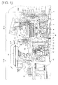
- Figure 1 is an overall schematic view of a hybrid drive force transmission device (an example of a drive force transmission device) according to a first embodiment. The overall configuration of the device will now be described with reference to Figure 1 .
- the hybrid drive force transmission device is provided with an engine Eng (drive source), a motor and clutch unit M/C, a transmission unit T/M, an engine output shaft 1, a clutch hub shaft 2, a clutch hub 3, a clutch drum shaft 4, a transmission input shaft 5, a clutch drum 6, a dry multi-plate clutch 7 (dry clutch), a slave cylinder 8, and a motor/generator 9.
- the slave cylinder 8 which hydraulically controls the engagement and disengagement of the dry multi-plate clutch 7, is generally referred to as a concentric slave cylinder (CSC).
- CSC concentric slave cylinder
- the motor/generator 9 and the transmission input shaft 5 and coupled by the clutch drum 6 and the clutch drum shaft 4 putting the vehicle into electric driving mode.
- the dry multi-plate clutch 7 is hydraulically engaged by the slave cylinder 8
- the engine Eng and motor/generator 9 and the engine output shaft 1 and clutch hub shaft 2 are coupled by a damper 21.
- the clutch hub 3 and the clutch drum 6 are coupled by the engaged dry multi-plate clutch 7 to put the vehicle into hybrid driving mode.
- the motor and clutch unit M/C comprises the dry multi-plate clutch 7, the slave cylinder 8, and the motor/generator 9.
- the dry multi-plate clutch 7 is coupled and connected to the engine Eng, and connects and disconnects the transmission of drive force from the engine Eng.
- the slave cylinder 8 hydraulically controls the engagement and disengagement of the dry multi-plate clutch 7.
- the motor/generator 9 is disposed at a position on the outer circumference of the clutch drum 6 of the dry multi-plate clutch 7, and engages in the transmission of motive force with the transmission input shaft 5.
- the motor and clutch unit M/C is provided with a cylinder housing 81 comprising a first clutch pressure fluid passage 85 leading to the slave cylinder 8, the seal integrity of the housing being maintained by an O-ring 10.
- the motor/generator 9 is a synchronous AC electric motor, and comprises a rotor support frame 91 provided integrally with the clutch drum 6, and a rotor 92, supported by and affixed to the rotor support frame 91, in which a permanent magnet is embedded. Also comprised are a stator 94 affixed to the cylinder housing 81 and separated from the rotor 92 by an air gap 93, and a stator coil 95 wound around the stator 94. A water jacket 96 through which cooling water is flushed is formed on the cylinder housing 81.
- the transmission unit T/M is coupled and connected to the motor and clutch unit M/C, and comprises a transmission housing 41, a V-belt continuously variable transmission mechanism 42, and an oil pump O/P.
- the V-belt continuously variable transmission mechanism 42 is built into the transmission housing 41 and features a V-belt wrapped between two pulleys; an infinite number of gear ratios can be obtained by altering the belt contact radius of the pulleys.
- the oil pump O/P is a hydraulic pressure source for generating hydraulic pressure required at various locations, and, using oil pump pressure as source pressure, directs hydraulic pressure from a control valve, not shown in the drawings, for adjusting various types of pressure, such as gear shift hydraulic pressure supplied to the pulley chambers or clutch/brake hydraulic pressure, to locations where hydraulic pressure is required.
- the transmission unit T/M is further provided with a forward/reverse switching mechanism 43, an oil tank 44, and an endplate 45.
- the endplate 45 comprises a second clutch pressure fluid passage 47 ( Figure 2 ).
- the oil pump O/P is driven by rotational drive torque from the transmission input shaft 5 via a chain drive mechanism.
- the chain drive mechanism comprises a drive-side sprocket 51 that rotates in tandem with the rotational driving of the transmission input shaft 5, a driven-side sprocket 52 for rotationally driving a pump shaft 57, and a chain 53 wrapped around the sprockets 51, 52.
- the drive-side sprocket 51 is interposed between the transmission input shaft 5 and the endplate 45, and is supported by a bushing 55 so as to be capable of rotating with respect to a stator shaft 54 affixed to the transmission housing 41.
- Rotational drive torque from the transmission input shaft 5 is transmitted by a first adapter 56 that mates via a spline with the transmission input shaft 5 and mates via a claw with the drive-side sprocket 51.
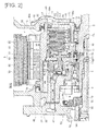
- Figure 2 is a cross-sectional view of the main parts of a motor and clutch unit of the hybrid drive force transmission device according to the first embodiment
- Figure 3 is an exploded perspective view of piston assembly pieces for a dry multi-plate clutch of the hybrid drive force transmission device according to the first embodiment.
- the configuration of the motor and clutch unit M/C will now be described with reference to Figures 2 and 3 .
- the clutch hub 3 is coupled to the engine output shaft 1 of the engine Eng.
- a drive plate 71 (first clutch plate) of the dry multi-plate clutch 7 is splined to the clutch hub 3, as shown in Figure 2 .
- the clutch drum 6 is coupled to the transmission input shaft 5 of the transmission unit T/M.
- a driven plate 72 (second clutch plate) of the dry multi-plate clutch 7 is splined to the clutch drum 6, as shown in Figure 2 .
- the dry multi-plate clutch 7 is configured by alternately arranging a plurality of drive plates 71, to both sides of which are attached frictional faces 73, 73, and driven plates 72 between the clutch hub 3 and the clutch drum 6. Engaging the dry multi-plate clutch 7 allows torque to be transmitted between the clutch hub 3 and the clutch drum 6, and releasing the dry multi-plate clutch 7 interrupts the transmission of torque between the clutch hub 3 and the clutch drum 6.
- the slave cylinder 8 is a hydraulic actuator for controlling the engagement and disengagement of the dry multi-plate clutch 7, and is disposed at a position between the transmission unit T/M and the clutch drum 6.
- the slave cylinder 8 comprises a piston 82 capable of sliding in a cylinder hole 80 in the cylinder housing 81, a first clutch pressure fluid passage 85, formed in the cylinder housing 81, for directing clutch pressure generated by the transmission unit T/M, and a cylinder fluid chamber 86 communicating with the first clutch pressure fluid passage 85.
- a needle bearing 87, a piston arm 83, a return spring 84, and an arm indentation plate 88 are interposed between the piston 82 and the dry multi-plate clutch 7.
- the piston arm 83 generates pressure for the dry multi-plate clutch 7 from the pressure from the slave cylinder 8, and is capable of sliding in a through-hole 61 formed in the clutch drum 6.
- the return spring 84 is interposed between the piston arm 83 and the clutch drum 6.
- the needle bearing 87 is interposed between the piston 82 and the piston arm 83, and keeps the piston 82 from rotating along with the piston arm 83.
- the arm indentation plate 88 is provided integrally with elastic accordion support members 89, 89, and inner and outer circumferential parts of the elastic accordion support members 89, 89 are pressure-fitted against the clutch drum 6.
- Leaked fluid from the piston arm 83 is prevented from flowing into the dry multi-plate clutch 7 by the arm indentation plate 88 and the elastic accordion support members 89, 89. That is, the arm indentation plate 88 and elastic accordion support members 89 sealed and immobilized at the position where the piston arm attaches to the clutch drum 6 serve to separate a wet space in which the slave cylinder 8 is disposed from the dry space in which the dry multi-plate clutch 7 is disposed.
- the piston arm 83 is constituted by a ring-shaped arm body 83a, and arm projections 83b projecting from the arm body 83a at four locations.
- the return spring 84 is constituted by a ring-shaped spring support plate 84a and a plurality of coil springs 84b affixed to the spring support plate 84a.
- the arm indentation plate 88 is pressed in place by the arm projections 83b of the piston arm 83.
- the elastic accordion support members 89, 89 are integrally provided inside and outside the arm indentation plate 88.
- a leaked/recovered fluid passage comprises a first bearing 12, a first seal member 31, a leaked fluid passage 32, a first recovered fluid passage 33, and a second recovered fluid passage 34, as shown in Figure 2 .
- leaked fluid from the sliding part of the piston 82 passes through the first recovered fluid passage 33 and the second recovered fluid passage 34, which are sealed by the first seal member 31, and returns to the transmission unit T/M.
- leaked fluid from the sliding part of the piston arm 83 passes through the leaked fluid passage 32, which is sealed by an elastic divider member (the arm indentation plate 88 and elastic accordion support members 89, 89), and the first recovered fluid passage 33 and the second recovered fluid passage 34, which are sealed by the first seal member 31, and returns to the transmission unit T/M.
- an elastic divider member the arm indentation plate 88 and elastic accordion support members 89, 89
- a bearing lubricant passage according to the first embodiment comprises a needle bearing 20, a second seal member 14, a first shaft core fluid passage 19, a second shaft core fluid passage 18, a lubricant passage 16, and a gap 17, as shown in Figure 2 .
- the bearing lubricant passage lubricates the bearings by carrying bearing lubricant from the transmission unit T/M through the needle bearing 20, the first bearing 12, which rotatably supports the clutch drum 6 with respect to the cylinder housing 81, and the needle bearing 87, which is interposed between the piston 82 and the piston arm 83, before returning it to the transmission unit T/M.
- the second seal member 14 is disposed between the clutch hub 3 and the clutch drum 6, as shown in Figure 2 .
- the second seal member 14 serves to prevent bearing lubricant from flowing from the wet space in which the slave cylinder 8 is disposed into the dry space in which the dry multi-plate clutch 7 is disposed.
- FIG. 4 and 5 shows various constituent members of the dry multi-plate clutch 7.
- the configuration of the dry multi-plate clutch 7 will now be described with reference to Figures 2 , 4, and 5 .
- the dry multi-plate clutch 7 connects and disconnects the transmission of drive force from the engine Eng, and, as shown in Figure 2 , is disposed within a clutch chamber 64 constituted by the closed space surrounded by the clutch hub shaft 2, the clutch hub 3, a clutch cover 6, and a front cover 60.
- the dry multi-plate clutch 7 is provided with the drive plate 71 (first clutch plate), the driven plate 72 (second clutch plate), a frictional face 73, and a front cover 60 (cover member) as component members.
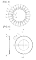
- the drive plate 71 is splined to the clutch hub 3, and comprises ventilation holes 74 at the position of the splined connection with the clutch hub 3 for admitting an air stream flowing in the axial direction.
- the drive plate 71 comprises the ventilation holes 74 at the positions of those spline tooth projections 75, out of spline teeth that intermesh with splines on the clutch hub 3, that project on an inner diameter side of the plate, these positions being located to the inside of face grooves 76 formed in the frictional face 73.
- a plurality of drive plates 71 (four in the first embodiment) are arranged so that their ventilation holes 74 communicate in the axial direction.
- the driven plate 72 is splined to the clutch drum 6, and comprises ventilation gaps 77 for admitting an air stream flowing in the axial direction at the position of the splined connection with the clutch drum 6.
- the ventilation gaps 77 form indentations 78 positioned in the center of spline tooth projections projecting on the outer diameter side of the plate, and are set by the open interstitial spaces formed upon engagement with the spline teeth of the clutch drum 6.
- a frictional face 73 is provided on both sides of the drive plate 71, and frictional surfaces thereof are pressed against the surface of the driven plate 72 when the clutch is engaged.
- the frictional face 73 is a ring-shaped plate member, and comprises face grooves 76 formed by lines radiating in the radial direction from positions on the inner diameter toward positions on the outer diameter.
- the face grooves 76 are of a depth such that they retain their grooved shape even if a certain degree of face wear occurs.
- the front cover 60 is integrally affixed to the cylinder housing 81, which is a motionless member supported by the first bearing 12 with respect to the clutch drum shaft 4, and covers the motor/generator 9 and the dry multi-plate clutch 7.
- the front cover 60 is a motionless member that is supported with respect to the clutch hub shaft 2 by a second bearing 13 and is sealed by a cover seal 15. That part of the interior space formed by the front cover 60 and cylinder housing 81 being covered nearer a clutch rotary shaft CL (equivalent to a rotor shaft) constitutes the clutch chamber 64 in which the dry multi-plate clutch 7 is housed, and the outer space of the clutch chamber 64 constitutes a motor chamber 65 in which the motor/generator 9 is housed.
- the clutch chamber 64 and the motor chamber 65 which are divided by a dust seal member 62, are dry spaces into which the flow of oil is blocked.
- the ejection of wear debris via an air stream effect of the dry multi-plate clutch 7 involves the ventilation holes 74, the ventilation gaps 77, and the face grooves 76.
- the ventilation holes 74 are formed at the locations of the spline joints between the drive plate 71 and the clutch hub 3, and admit an air stream flowing in the axial direction ( Figure 4 ).
- the ventilation gaps 77 are formed at the locations of the spline joints between the driven plate 72 and the clutch drum 6, and admit an air stream flowing in the axial direction ( Figure 5 ).
- the face grooves 76 are formed by lines radiating in the radial direction from positions on the inner diameter of the frictional face 73 toward positions on the outer diameter thereof, and admit an air stream flowing in the radial direction ( Figure 4 ).
- the ejection of wear debris via an air stream effect of the front cover 60 involves an air intake port 66, an air venting port 67, and a splash guard 68, as shown in Figures 2 and 6 .
- the air intake port 66 is a hole for drawing air into the clutch chamber 64 via the closed space, and, out of the front cover 60 disposed on the side of the dry multi-plate clutch 7, is provided extending in the axial direction toward the inner diameter side of the clutch plates 71, 72, as shown in Figure 2 .
- the specific radial direction position of the air intake port 66 is matched to the radial direction position of the dry multi-plate clutch 7 in which the ventilation holes 74 for admitting the air stream flowing in the axial direction are set.
- the air intake port 66 is an arcuate hole formed in the front cover 60.
- the air venting port 67 is a hole for venting an air stream from within the clutch chamber 64 via the closed space to the open air, and, out of the front cover 60 disposed on the side of the dry multi-plate clutch 7, is provided extending in the axial direction to the outer diameter side of the clutch plates 71, 72, as shown in Figure 2 .
- the specific radial direction position of the air venting port 67 is matched to the radial direction position of the dry multi-plate clutch 7 in which the ventilation gaps 77 for admitting the air stream flowing in the axial direction are set.
- the air venting port 67 is an arcuate hole formed in the front cover 60, and has a greater area than the air intake port 66.
- the splash guard 68 covers the air intake port 66 and the air venting port 67 of the front cover 60 in order to prevent the infiltration of water from the air intake port 66 and the air venting port 67 provided in the front cover 60 into the clutch chamber 64.
- the damper 21, which attenuates variations in drive force from the engine Eng constituting the drive source, is disposed at a position outside the splash guard 68.
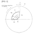
- the splash guard 68 is provided with a covering guard surface 68a, an outer circumferential guard surface 68b, an inner circumferential guard surface 68c, a side guard surface 68d, and an opening 68e.
- the shape of the side surface of the covering guard surface 68a conforms to the shape of the outer surface of the front cover 60, and the front surface has a fan shape having an angle of spread of roughly 90° so as to cover the air intake port 66 and the air venting port 67.
- the covering guard surface 68a prevents the infiltration of water from the head-on direction (axial direction) in the air intake port 66 and the air venting port 67.
- the outer circumferential guard surface 68b has an arc shape that closes off the outer circumference of the covering guard surface 68a.
- the outer circumferential guard surface 68b prevents the infiltration of water from above (in the radial direction) into the air intake port 66 or the air venting port 67 when water drawn up by the splash guard 68 falls down.
- the inner circumferential guard surface 68c has an arc shape that closes off the inner circumference of the covering guard surface 68a.
- the inner circumferential guard surface 68c prevents the infiltration of water from below (in the radial direction) into the air intake port 66 or the air venting port 67 when water is splashed from the direction of the clutch rotary shaft CL.
- the side guard surface 68d has the shape of a straight line in the radial direction that closes off part of the covering guard surface 68a.
- the side guard surface 68d is disposed upstream of the damper 21 with respect to the direction of rotation, and prevents the infiltration of water from the lateral direction (in the circumferential direction) into the air intake port 66 and the air venting port 67 when water is drawn up by the rotation of the damper 21.
- the opening 68e has the shape of a straight line in the radial direction leaving the other side of the covering guard surface 68a in order to take in air through the air intake port 66 and eject air streams from the air venting port 67.
- the opening 68e is disposed downstream of the damper 21 with respect to the direction of rotation. When water is drawn up by the rotation of the damper 21, the fact that the opening faces in the direction opposite that in which water is drawn up keeps water from directly falling upon the air intake port 66 or the air venting port 67.
- the direction in which the opening 68e faces is angled so that the opening is tilted with respect to the vertical direction so as to face downwards when the splash guard is installed in a vehicle (i.e., an inclination of roughly 45°).
- the description of the operation of the hybrid drive force transmission device according to the first embodiment will be divided into descriptions of the engagement and disengagement of the clutch by the slave cylinder, the ejection of wear debris by the air stream effect, and the prevention of water infiltration and ensuring of wear debris ejection by the splash guard.
- the operating fluid being supplied to the cylinder fluid chamber 86 drains through the clutch pressure fluid passage 85 into the transmission unit T/M, reducing the hydraulic pressure force acting upon the piston 82, in turn causing the biasing force exerted by the return spring 84 to exceed the hydraulic pressure force, thus causing the integrated piston arm 83 and arm indentation plate 88 to make a stroke in the leftward direction as seen in Figure 2 .
- the engagement force being transmitted to the arm indentation plate 88 is thereby released, disengaging the dry multi-plate clutch 7.
- this centrifugal fan effect sends air in a radial direction from a zone B in the area by the clutch hub 3 to a zone C in the area by the clutch drum 6, increasing the air pressure near the clutch drum 6 (positive pressure), and decreasing the air pressure near the clutch hub 3 (negative pressure).
- the difference in air pressure generates a radial direction air stream E of air moving in the radial direction from the area by the clutch hub 3 to the area by the clutch drum 6.
- the pressure at the inner diameter side of the dry multi-plate clutch 7 becomes less than atmospheric pressure (negative pressure), and the pressure at the outer diameter side of the dry multi-plate clutch 7 becomes greater than atmospheric pressure (positive pressure), creating a pressure relationship such that: air pressure at clutch outer diameter > atmospheric pressure > air pressure at clutch inner diameter.
- this radial direction air stream E creates a difference in air pressure between the external air constituting the atmospheric pressure and the inner diameter side of the clutch constituting the negative pressure. Accordingly, as shown in Figure 7 , external air taken in through the air intake port 66 passes through various ventilation holes 74, creating an inner diameter-side axial direction air stream F that flows through the area by the clutch hub 3, where the air pressure is reduced.
- the spline joint part of the driven plate 72 has low air resistance due to the presence of the extra space in order to ensure the movement of the plate.
- the presence of the ventilation gaps 77 for admitting axial direction air streams at the location of the spline joint between the driven plate 72 and the clutch drum 6 further reduces air resistance.
- the generation of the radial direction air stream E creates a difference in air pressure between the outer diameter side of the clutch constituting the positive pressure and the external air constituting the atmospheric pressure.
- the air stream changing its course from the inside diameter-side axial direction to the radial direction and flowing into the area by the clutch drum 6 generates an outer diameter-side axial direction air stream G passing from the ventilation gaps 77 at the spline joint through the air venting port 67 to the external air.
- the front cover 60 disposed on the side of the dry multi-plate clutch 7 comprises the air intake port 66 for taking external air into the closed space constituted by the clutch chamber 64, and the air venting port 67 for ejecting an air stream from within the clutch chamber 64 to the external air.
- the front cover 60 is also provided with the splash guard 68, which covers the air intake port 66 and the air venting port 67 and comprises the opening 68e.
- Water pooling in the damper chamber may be lifted to a position higher than the splash guard 68 due to the rotation of the damper or shaking in the unit. Water lifted above the splash guard 68 in this way falls down toward the splash guard 68, as indicated by arrow I in Figure 6 , but is caught by the closed arcuate outer circumferential guard surface 68b. Because the opening 68e is angled so as to be oriented downward with respect to the vertical direction when the splash guard is installed in a vehicle, the water reliably circumvents the opening 68e and falls downward, as indicated by arrow J in Figure 6 . The infiltration of water falling from a position higher than the splash guard 68 into the air intake port 66 or the air venting port 67 is thereby prevented.
- the presence of the opening 68e for taking in external air through the air intake port 66 and ejecting an air stream through the air venting port 67 in the splash guard 68 means that the generation of an air stream for ejecting wear debris from the surface of the frictional faces 73 is not impeded.
- the opening 68e is added to the flow of the air stream formed by the pressure relationship of clutch outer diameter-side air pressure > atmospheric pressure > clutch inner diameter-side air pressure.
- the air stream path (F to E to G) flowing from the external air through the opening 68e, the air intake port 66, the clutch inner diameter-side axial direction gap, the clutch radial direction gap, the clutch outer diameter side axial direction gap, the air venting port 67, and the opening 68e back to the external air is still formed.
- the hybrid drive force transmission device yields the following effects.
- water can be prevented from infiltrating through the opening 68e into the air intake port 66 or the air venting port 67 when water lifted to a position higher than the splash guard 68 falls downward.
- the opening in the splash guard is defined with respect to the vertical axis.
- Figure 8 is an illustration of the direction of an opening in a splash guard of a hybrid drive force transmission device according to the second embodiment.
- the direction in which the opening 68e in the splash guard 68 according to the second embodiment faces is angled so as to be inclined by a predetermined angle ⁇ in the rotational direction of the damper 21 with respect to a vertical axis K.
- the hybrid drive force transmission device yields the following effects.
- the direction in which the opening 68e in the splash guard 68 faces is set to an angle so as to be inclined in the rotational direction of the damper 4 with respect to a vertical axis K by a predetermined angle ⁇ .
- water can be prevented from infiltrating through the opening 68e into the air intake port 66 or the air venting port 67 when water lifted to a position higher than the splash guard 68 falls downward.
- a dry multi-plate clutch was used as the dry clutch, but a single-plate dry clutch may also be used.
- the dry clutch was a normally open clutch.
- a normally closed dry clutch utilizing a diaphragm spring or the like may also be used.
- the drive plate 71 was splined to the clutch hub 3, and the driven plate 72 was splined to the clutch drum 6.
- the drive plate it is also possible for the drive plate to be splined to the clutch drum and the driven plate to be splined to the clutch hub.
- the drive plate 71 comprised a frictional face 73.
- the driven plate it is also possible for the driven plate to comprise a frictional face.
- the ventilation holes 74, ventilation gaps 77, face grooves 76, and the like were provided in order to secure an air stream path within the dry multi-plate clutch 7.
- the gaps present at the spline joint create a path for axial direction air streams, and the gap between the plates forms a path for radial direction air streams. Accordingly, it is not essential to provide the ventilation holes 74, ventilation gaps 77, face grooves 76, or the like.
- the direction in which the opening 68e in the splash guard 68 faces is angled so that the opening faces downward with respect to the vertical axis when the splash guard is installed in a vehicle.
- any splash guard is acceptable as long as the opening is angled so that the infiltration of water from the opening into the air intake port or the air venting port when water lifted to a position higher that the splash guard falls downward is prevented.
- the direction in which the opening faces may be set to an angle anywhere from one such that the opening is only slightly oriented downward with respect to the vertical axis when the splash guard is installed in a vehicle to one such that the opening is orthogonal to the vertical axis (i.e., completely downward-facing) when the splash guard is installed in a vehicle.
- the first and second embodiments feature examples of application to a hybrid drive force transmission device equipped with an engine and a motor/generator, in which a dry multi-plate clutch is used to shift driving modes.
- the present invention can also be applied to an engine drive force transmission device, such as that for an engine vehicle, in which only an engine is used as a drive source and a dry clutch is used to start off.
- the present invention can also be applied to a motor drive force transmission device, such as that for an electric vehicle or a fuel cell vehicle, in which only a motor/generator is used as a drive source and a dry clutch is used to start off.
Landscapes
- Engineering & Computer Science (AREA)
- General Engineering & Computer Science (AREA)
- Mechanical Engineering (AREA)
- Hydraulic Clutches, Magnetic Clutches, Fluid Clutches, And Fluid Joints (AREA)
- Mechanical Operated Clutches (AREA)
- Hybrid Electric Vehicles (AREA)
Abstract
Description
- The present invention relates to a drive force transmission device, applied to a vehicle drivetrain, in which a dry clutch for connecting and disconnecting drive force transmission is disposed within a closed space.
- A hybrid drive force transmission device in which an engine, a motor, a clutch unit, and a transmission unit are coupled and connected to each other is known in the art. For the motor and the clutch unit, a dry multi-plate clutch is disposed inside an electric motor. Specifically, there are provided a clutch hub coupled to an output shaft of the engine, a clutch drum to which a rotor of the electric motor is affixed and which is coupled to an input shaft of the transmission, and a dry multi-plate clutch interposed between the clutch hub and the clutch drum (see, for example, patent citation 1).
- Patent citation 1: Unexamined Japanese Patent Application Publication
2010-151313 - However, the dry multi-plate clutch of this conventional hybrid drive force transmission device is covered by a unit housing and housed within a dry space sealed by a seal member. As a result, wear debris from the frictional face generated by repeated clutch engagement and disengagement must be ejected from the dry space in order to prevent wear debris-induced scraping. One possible method of doing this would be to provide a hole in a cover member of the dry multi-plate clutch; however, this would create the problem that, if water were to infiltrate the damper chamber, water drawn up by the rotation of the damper would infiltrate into the clutch chamber through the hole provided in the cover member. On the other hand, covering the hole entirely would lead of the problem of being incapable of ejecting wear debris.
- The present invention was conceived in view of the problems described above, it being an object thereof to provide a drive force transmission device that is capable of preventing water from infiltrating into a closed space in which a dry clutch is disposed and ensuring that dry clutch wear debris can be ejected outside.
- In order to achieve the abovementioned object, the present invention is a drive force transmission device in which a dry clutch for connecting and disconnecting drive force transmission is disposed within a closed space, wherein the dry clutch is provided with a first clutch plate, a second clutch plate, a frictional face, a cover member, and a splash guard.
- The first clutch plate is splined to the clutch hub.
- The second clutch plate is splined to the clutch drum.
- The frictional face is provided on either the first clutch plate or the second clutch plate, and a frictional surface thereof is pressed against a surface of the other plate when the clutch is engaged.
- The cover member comprises an air intake port for drawing external air into the closed space, and an air venting port for venting an air stream from the closed space into the external air.
- The splash guard is provided so as to cover the air intake port and the air venting port of the cover member, and comprises an opening for drawing in external air through the air intake port and venting an air stream from the air venting port.
- As described above, the cover member disposed on the side of the dry clutch comprises an air intake port for introducing external air into the closed space and an air venting port for venting an air stream from the closed space into the external air. The cover member is provided with a splash guard that covers the air intake port and the air venting port and comprises an opening.
- As a result, any water potentially infiltrating from the exterior through the air intake port or air venting port provided in the cover member into the closed space in which the dry clutch is disposed is prevented from infiltrating the closed space by the splash guard.
- The splash guard comprises an opening allowing for communication with the external air and covers the air intake port and the air venting port, and thus does not impede the generation of an air stream for ejecting wear debris from the surface of the frictional face to the exterior. Specifically, the pressure relationship engendered by the air pressure on the outer diameter side of the clutch being greater than the atmospheric pressure, which is in turn greater than the air pressure on the inner diameter side of the clutch generates an air stream that flows along a path going from the external air through the opening, the air intake port, a clutch inner diameter-side axial direction gap, a clutch radial direction gap, a clutch outer diameter side axial direction gap, the air venting port, the opening, and back to the external air.
- As a result, it is possible to prevent water from infiltrating a closed space in which a dry clutch is disposed and ensure that dry clutch wear debris can be ejected outside.
-
- [
Figure 1 ] An overall schematic view of a hybrid drive force transmission device (an example of a drive force transmission device) according to a first embodiment. - [
Figure 2 ] A cross-sectional view of the main parts of a motor and clutch unit of the hybrid drive force transmission device according to the first embodiment. - [
Figure 3 ] An exploded perspective view of piston assembly pieces for a dry multi-plate clutch of the hybrid drive force transmission device according to the first embodiment. - [
Figure 4 ] A head-on view of a drive plate for the dry multi-plate clutch of the hybrid drive force transmission device according to the first embodiment. - [
Figure 5 ] A cross-sectional view along line A-A (a) and a head-on view (b) of a driven plate for the dry multi-plate clutch of the hybrid drive force transmission device according to the first embodiment. - [
Figure 6 ] A side view of a front cover on which a splash guard for the dry multi-plate clutch of the hybrid drive force transmission device according to the first embodiment is provided. - [
Figure 7 ] An operational illustration of wear debris being ejected in the hybrid drive force transmission device according to the first embodiment. - [
Figure 8 ] An illustration of the direction of an opening in a splash guard of a hybrid drive force transmission device according to a second embodiment. - The following is a description of a best mode for carrying out the drive force transmission device according to the present invention on the basis of a embodiment and a second embodiment shown in the drawings.
- First, the configuration of the first embodiment will be described.
- The description of the configuration of the hybrid drive force transmission device according to the first embodiment will be divided into the overall configuration, the configuration of the motor and clutch unit, the configuration of the dry multi-plate clutch, and the ejection of wear debris by an air stream effect.
-
Figure 1 is an overall schematic view of a hybrid drive force transmission device (an example of a drive force transmission device) according to a first embodiment. The overall configuration of the device will now be described with reference toFigure 1 . - As shown in
Figure 1 , the hybrid drive force transmission device according to the first embodiment is provided with an engine Eng (drive source), a motor and clutch unit M/C, a transmission unit T/M, an engine output shaft 1, aclutch hub shaft 2, aclutch hub 3, aclutch drum shaft 4, atransmission input shaft 5, aclutch drum 6, a dry multi-plate clutch 7 (dry clutch), aslave cylinder 8, and a motor/generator 9. - The
slave cylinder 8, which hydraulically controls the engagement and disengagement of the dry multi-plate clutch 7, is generally referred to as a concentric slave cylinder (CSC). - In the hybrid drive force transmission device according to the first embodiment, when the normally open dry multi-plate clutch 7 is disengaged, the motor/
generator 9 and thetransmission input shaft 5 and coupled by theclutch drum 6 and theclutch drum shaft 4, putting the vehicle into electric driving mode. When the dry multi-plate clutch 7 is hydraulically engaged by theslave cylinder 8, the engine Eng and motor/generator 9 and the engine output shaft 1 andclutch hub shaft 2 are coupled by adamper 21. Theclutch hub 3 and theclutch drum 6 are coupled by the engaged dry multi-plate clutch 7 to put the vehicle into hybrid driving mode. - The motor and clutch unit M/C comprises the dry multi-plate clutch 7, the
slave cylinder 8, and the motor/generator 9. The dry multi-plate clutch 7 is coupled and connected to the engine Eng, and connects and disconnects the transmission of drive force from the engine Eng. Theslave cylinder 8 hydraulically controls the engagement and disengagement of the dry multi-plate clutch 7. The motor/generator 9 is disposed at a position on the outer circumference of theclutch drum 6 of the dry multi-plate clutch 7, and engages in the transmission of motive force with thetransmission input shaft 5. - The motor and clutch unit M/C is provided with a
cylinder housing 81 comprising a first clutchpressure fluid passage 85 leading to theslave cylinder 8, the seal integrity of the housing being maintained by an O-ring 10. - The motor/
generator 9 is a synchronous AC electric motor, and comprises arotor support frame 91 provided integrally with theclutch drum 6, and arotor 92, supported by and affixed to therotor support frame 91, in which a permanent magnet is embedded. Also comprised are astator 94 affixed to thecylinder housing 81 and separated from therotor 92 by anair gap 93, and astator coil 95 wound around thestator 94. Awater jacket 96 through which cooling water is flushed is formed on thecylinder housing 81. - The transmission unit T/M is coupled and connected to the motor and clutch unit M/C, and comprises a
transmission housing 41, a V-belt continuouslyvariable transmission mechanism 42, and an oil pump O/P. The V-belt continuouslyvariable transmission mechanism 42 is built into thetransmission housing 41 and features a V-belt wrapped between two pulleys; an infinite number of gear ratios can be obtained by altering the belt contact radius of the pulleys. The oil pump O/P is a hydraulic pressure source for generating hydraulic pressure required at various locations, and, using oil pump pressure as source pressure, directs hydraulic pressure from a control valve, not shown in the drawings, for adjusting various types of pressure, such as gear shift hydraulic pressure supplied to the pulley chambers or clutch/brake hydraulic pressure, to locations where hydraulic pressure is required. The transmission unit T/M is further provided with a forward/reverse switching mechanism 43, anoil tank 44, and anendplate 45. Theendplate 45 comprises a second clutch pressure fluid passage 47 (Figure 2 ). - The oil pump O/P is driven by rotational drive torque from the
transmission input shaft 5 via a chain drive mechanism. The chain drive mechanism comprises a drive-side sprocket 51 that rotates in tandem with the rotational driving of thetransmission input shaft 5, a driven-side sprocket 52 for rotationally driving apump shaft 57, and achain 53 wrapped around thesprockets side sprocket 51 is interposed between thetransmission input shaft 5 and theendplate 45, and is supported by abushing 55 so as to be capable of rotating with respect to astator shaft 54 affixed to thetransmission housing 41. Rotational drive torque from thetransmission input shaft 5 is transmitted by afirst adapter 56 that mates via a spline with thetransmission input shaft 5 and mates via a claw with the drive-side sprocket 51. -
Figure 2 is a cross-sectional view of the main parts of a motor and clutch unit of the hybrid drive force transmission device according to the first embodiment, andFigure 3 is an exploded perspective view of piston assembly pieces for a dry multi-plate clutch of the hybrid drive force transmission device according to the first embodiment. The configuration of the motor and clutch unit M/C will now be described with reference toFigures 2 and3 . - The
clutch hub 3 is coupled to the engine output shaft 1 of the engine Eng. A drive plate 71 (first clutch plate) of the dry multi-plate clutch 7 is splined to theclutch hub 3, as shown inFigure 2 . - The
clutch drum 6 is coupled to thetransmission input shaft 5 of the transmission unit T/M. A driven plate 72 (second clutch plate) of the dry multi-plate clutch 7 is splined to theclutch drum 6, as shown inFigure 2 . - The dry multi-plate clutch 7 is configured by alternately arranging a plurality of
drive plates 71, to both sides of which are attached frictional faces 73, 73, and drivenplates 72 between theclutch hub 3 and theclutch drum 6. Engaging the dry multi-plate clutch 7 allows torque to be transmitted between theclutch hub 3 and theclutch drum 6, and releasing the dry multi-plate clutch 7 interrupts the transmission of torque between theclutch hub 3 and theclutch drum 6. - The
slave cylinder 8 is a hydraulic actuator for controlling the engagement and disengagement of the dry multi-plate clutch 7, and is disposed at a position between the transmission unit T/M and theclutch drum 6. As shown inFigure 2 , theslave cylinder 8 comprises apiston 82 capable of sliding in acylinder hole 80 in thecylinder housing 81, a first clutchpressure fluid passage 85, formed in thecylinder housing 81, for directing clutch pressure generated by the transmission unit T/M, and acylinder fluid chamber 86 communicating with the first clutchpressure fluid passage 85. As shown inFigure 2 , aneedle bearing 87, apiston arm 83, areturn spring 84, and anarm indentation plate 88 are interposed between thepiston 82 and the dry multi-plate clutch 7. - The
piston arm 83 generates pressure for the dry multi-plate clutch 7 from the pressure from theslave cylinder 8, and is capable of sliding in a through-hole 61 formed in theclutch drum 6. Thereturn spring 84 is interposed between thepiston arm 83 and theclutch drum 6. Theneedle bearing 87 is interposed between thepiston 82 and thepiston arm 83, and keeps thepiston 82 from rotating along with thepiston arm 83. Thearm indentation plate 88 is provided integrally with elasticaccordion support members accordion support members clutch drum 6. Leaked fluid from thepiston arm 83 is prevented from flowing into the dry multi-plate clutch 7 by thearm indentation plate 88 and the elasticaccordion support members arm indentation plate 88 and elasticaccordion support members 89 sealed and immobilized at the position where the piston arm attaches to theclutch drum 6 serve to separate a wet space in which theslave cylinder 8 is disposed from the dry space in which the dry multi-plate clutch 7 is disposed. - As shown in
Figure 3 , thepiston arm 83 is constituted by a ring-shapedarm body 83a, andarm projections 83b projecting from thearm body 83a at four locations. - As shown in
Figure 3 , thereturn spring 84 is constituted by a ring-shapedspring support plate 84a and a plurality ofcoil springs 84b affixed to thespring support plate 84a. - As shown in
Figure 2 , thearm indentation plate 88 is pressed in place by thearm projections 83b of thepiston arm 83. As shown inFigure 3 , the elasticaccordion support members arm indentation plate 88. - A leaked/recovered fluid passage according to the first embodiment comprises a
first bearing 12, afirst seal member 31, a leakedfluid passage 32, a first recoveredfluid passage 33, and a secondrecovered fluid passage 34, as shown inFigure 2 . Specifically, leaked fluid from the sliding part of thepiston 82 passes through the first recoveredfluid passage 33 and the second recoveredfluid passage 34, which are sealed by thefirst seal member 31, and returns to the transmission unit T/M. In addition, leaked fluid from the sliding part of thepiston arm 83 passes through the leakedfluid passage 32, which is sealed by an elastic divider member (thearm indentation plate 88 and elasticaccordion support members 89, 89), and the first recoveredfluid passage 33 and the second recoveredfluid passage 34, which are sealed by thefirst seal member 31, and returns to the transmission unit T/M. - A bearing lubricant passage according to the first embodiment comprises a
needle bearing 20, asecond seal member 14, a first shaftcore fluid passage 19, a second shaftcore fluid passage 18, a lubricant passage 16, and agap 17, as shown inFigure 2 . The bearing lubricant passage lubricates the bearings by carrying bearing lubricant from the transmission unit T/M through theneedle bearing 20, thefirst bearing 12, which rotatably supports theclutch drum 6 with respect to thecylinder housing 81, and theneedle bearing 87, which is interposed between thepiston 82 and thepiston arm 83, before returning it to the transmission unit T/M. - The
second seal member 14 is disposed between theclutch hub 3 and theclutch drum 6, as shown inFigure 2 . Thesecond seal member 14 serves to prevent bearing lubricant from flowing from the wet space in which theslave cylinder 8 is disposed into the dry space in which the dry multi-plate clutch 7 is disposed. - [Configuration of the dry multi-plate clutch]
Figures 4 and 5 shows various constituent members of the dry multi-plate clutch 7. The configuration of the dry multi-plate clutch 7 will now be described with reference toFigures 2 ,4, and 5 . - The dry multi-plate clutch 7 connects and disconnects the transmission of drive force from the engine Eng, and, as shown in
Figure 2 , is disposed within aclutch chamber 64 constituted by the closed space surrounded by theclutch hub shaft 2, theclutch hub 3, aclutch cover 6, and afront cover 60. The dry multi-plate clutch 7 is provided with the drive plate 71 (first clutch plate), the driven plate 72 (second clutch plate), africtional face 73, and a front cover 60 (cover member) as component members. - The
drive plate 71 is splined to theclutch hub 3, and comprises ventilation holes 74 at the position of the splined connection with theclutch hub 3 for admitting an air stream flowing in the axial direction. As shown inFigure 4 , thedrive plate 71 comprises the ventilation holes 74 at the positions of thosespline tooth projections 75, out of spline teeth that intermesh with splines on theclutch hub 3, that project on an inner diameter side of the plate, these positions being located to the inside offace grooves 76 formed in thefrictional face 73. As shown inFigure 2 , a plurality of drive plates 71 (four in the first embodiment) are arranged so that theirventilation holes 74 communicate in the axial direction. - The driven
plate 72 is splined to theclutch drum 6, and comprisesventilation gaps 77 for admitting an air stream flowing in the axial direction at the position of the splined connection with theclutch drum 6. As shown inFigure 5 , theventilation gaps 77form indentations 78 positioned in the center of spline tooth projections projecting on the outer diameter side of the plate, and are set by the open interstitial spaces formed upon engagement with the spline teeth of theclutch drum 6. - A
frictional face 73 is provided on both sides of thedrive plate 71, and frictional surfaces thereof are pressed against the surface of the drivenplate 72 when the clutch is engaged. As shown inFigure 4 , thefrictional face 73 is a ring-shaped plate member, and comprisesface grooves 76 formed by lines radiating in the radial direction from positions on the inner diameter toward positions on the outer diameter. Theface grooves 76 are of a depth such that they retain their grooved shape even if a certain degree of face wear occurs. - The
front cover 60 is integrally affixed to thecylinder housing 81, which is a motionless member supported by thefirst bearing 12 with respect to theclutch drum shaft 4, and covers the motor/generator 9 and the dry multi-plate clutch 7. Specifically, thefront cover 60 is a motionless member that is supported with respect to theclutch hub shaft 2 by asecond bearing 13 and is sealed by acover seal 15. That part of the interior space formed by thefront cover 60 andcylinder housing 81 being covered nearer a clutch rotary shaft CL (equivalent to a rotor shaft) constitutes theclutch chamber 64 in which the dry multi-plate clutch 7 is housed, and the outer space of theclutch chamber 64 constitutes amotor chamber 65 in which the motor/generator 9 is housed. Theclutch chamber 64 and themotor chamber 65, which are divided by adust seal member 62, are dry spaces into which the flow of oil is blocked. - The manner in which wear debris is ejected from the dry multi-plate clutch 7 by an air stream effect will now be described with reference to
Figures 2 and4-6 . - The ejection of wear debris via an air stream effect of the dry multi-plate clutch 7 involves the ventilation holes 74, the
ventilation gaps 77, and theface grooves 76. - The ventilation holes 74 are formed at the locations of the spline joints between the
drive plate 71 and theclutch hub 3, and admit an air stream flowing in the axial direction (Figure 4 ). - The
ventilation gaps 77 are formed at the locations of the spline joints between the drivenplate 72 and theclutch drum 6, and admit an air stream flowing in the axial direction (Figure 5 ). - The
face grooves 76 are formed by lines radiating in the radial direction from positions on the inner diameter of thefrictional face 73 toward positions on the outer diameter thereof, and admit an air stream flowing in the radial direction (Figure 4 ). - The ejection of wear debris via an air stream effect of the
front cover 60 involves anair intake port 66, anair venting port 67, and asplash guard 68, as shown inFigures 2 and6 . - The
air intake port 66 is a hole for drawing air into theclutch chamber 64 via the closed space, and, out of thefront cover 60 disposed on the side of the dry multi-plate clutch 7, is provided extending in the axial direction toward the inner diameter side of theclutch plates Figure 2 . The specific radial direction position of theair intake port 66 is matched to the radial direction position of the dry multi-plate clutch 7 in which the ventilation holes 74 for admitting the air stream flowing in the axial direction are set. As shown inFigure 6 , theair intake port 66 is an arcuate hole formed in thefront cover 60. - The
air venting port 67 is a hole for venting an air stream from within theclutch chamber 64 via the closed space to the open air, and, out of thefront cover 60 disposed on the side of the dry multi-plate clutch 7, is provided extending in the axial direction to the outer diameter side of theclutch plates Figure 2 . The specific radial direction position of theair venting port 67 is matched to the radial direction position of the dry multi-plate clutch 7 in which theventilation gaps 77 for admitting the air stream flowing in the axial direction are set. As shown inFigure 6 , theair venting port 67 is an arcuate hole formed in thefront cover 60, and has a greater area than theair intake port 66. - As shown in
Figure 2 , thesplash guard 68 covers theair intake port 66 and theair venting port 67 of thefront cover 60 in order to prevent the infiltration of water from theair intake port 66 and theair venting port 67 provided in thefront cover 60 into theclutch chamber 64. Thedamper 21, which attenuates variations in drive force from the engine Eng constituting the drive source, is disposed at a position outside thesplash guard 68. Specifically, thesplash guard 68 is provided with a coveringguard surface 68a, an outercircumferential guard surface 68b, an innercircumferential guard surface 68c, aside guard surface 68d, and anopening 68e. - As shown in
Figures 2 and6 , the shape of the side surface of the coveringguard surface 68a conforms to the shape of the outer surface of thefront cover 60, and the front surface has a fan shape having an angle of spread of roughly 90° so as to cover theair intake port 66 and theair venting port 67. The coveringguard surface 68a prevents the infiltration of water from the head-on direction (axial direction) in theair intake port 66 and theair venting port 67. - As shown in
Figures 2 and6 , the outercircumferential guard surface 68b has an arc shape that closes off the outer circumference of the coveringguard surface 68a. The outercircumferential guard surface 68b prevents the infiltration of water from above (in the radial direction) into theair intake port 66 or theair venting port 67 when water drawn up by thesplash guard 68 falls down. - As shown in
Figures 2 and6 , the innercircumferential guard surface 68c has an arc shape that closes off the inner circumference of the coveringguard surface 68a. The innercircumferential guard surface 68c prevents the infiltration of water from below (in the radial direction) into theair intake port 66 or theair venting port 67 when water is splashed from the direction of the clutch rotary shaft CL. - As shown in
Figure 6 , theside guard surface 68d has the shape of a straight line in the radial direction that closes off part of the coveringguard surface 68a. Theside guard surface 68d is disposed upstream of thedamper 21 with respect to the direction of rotation, and prevents the infiltration of water from the lateral direction (in the circumferential direction) into theair intake port 66 and theair venting port 67 when water is drawn up by the rotation of thedamper 21. - As shown in
Figure 6 , theopening 68e has the shape of a straight line in the radial direction leaving the other side of the coveringguard surface 68a in order to take in air through theair intake port 66 and eject air streams from theair venting port 67. Theopening 68e is disposed downstream of thedamper 21 with respect to the direction of rotation. When water is drawn up by the rotation of thedamper 21, the fact that the opening faces in the direction opposite that in which water is drawn up keeps water from directly falling upon theair intake port 66 or theair venting port 67. In addition, as shown inFigure 6 , the direction in which theopening 68e faces is angled so that the opening is tilted with respect to the vertical direction so as to face downwards when the splash guard is installed in a vehicle (i.e., an inclination of roughly 45°). - Next, the operation of the present invention will be described.
- The description of the operation of the hybrid drive force transmission device according to the first embodiment will be divided into descriptions of the engagement and disengagement of the clutch by the slave cylinder, the ejection of wear debris by the air stream effect, and the prevention of water infiltration and ensuring of wear debris ejection by the splash guard.
- The engagement and disengagement of the dry multi-plate clutch 7 by the
slave cylinder 8 will now be described with reference toFigure 2 . - When the dry multi-plate clutch 7 is engaged by the
slave cylinder 8, clutch hydraulic pressure generated by the transmission unit T/M is supplied to thecylinder fluid chamber 86 via the first clutchpressure fluid passage 85 formed in thecylinder housing 81. As a result, hydraulic pressure force equivalent to the product of the hydraulic pressure and the area subjected to pressure acts upon thepiston 82, causing thepiston 82 to make a stroke in the rightward direction as seen inFigure 2 against the biasing force of thereturn spring 84 interposed between thepiston arm 83 and theclutch drum 6. Engagement force equivalent to the difference between the hydraulic pressure force and the biasing force is then transmitted from thepiston 82 to theneedle bearing 87, from there to thepiston arm 83, and finally to thearm indentation plate 88, thereby pressing thedrive plate 71 and the drivenplate 72 together and engaging the dry multi-plate clutch 7. - When the engaged dry multi-plate clutch 7 is disengaged, the operating fluid being supplied to the
cylinder fluid chamber 86 drains through the clutchpressure fluid passage 85 into the transmission unit T/M, reducing the hydraulic pressure force acting upon thepiston 82, in turn causing the biasing force exerted by thereturn spring 84 to exceed the hydraulic pressure force, thus causing theintegrated piston arm 83 andarm indentation plate 88 to make a stroke in the leftward direction as seen inFigure 2 . The engagement force being transmitted to thearm indentation plate 88 is thereby released, disengaging the dry multi-plate clutch 7. - As the dry multi-plate clutch 7 is repeatedly engaged and disengaged, as described above, the surface of the frictional face will slough off and accumulate between the
clutch plates Figure 7 . - When at least one of the
clutch hub 3 and theclutch drum 6 rotates around the clutch rotary shaft CL, the presence of theface grooves 76 on thefrictional face 73 generates a centrifugal fan effect using theclutch hub 3, which has africtional face 73 on both sides, as blades. - As shown in
Figure 7 , this centrifugal fan effect sends air in a radial direction from a zone B in the area by theclutch hub 3 to a zone C in the area by theclutch drum 6, increasing the air pressure near the clutch drum 6 (positive pressure), and decreasing the air pressure near the clutch hub 3 (negative pressure). The difference in air pressure generates a radial direction air stream E of air moving in the radial direction from the area by theclutch hub 3 to the area by theclutch drum 6. That is, the pressure at the inner diameter side of the dry multi-plate clutch 7 becomes less than atmospheric pressure (negative pressure), and the pressure at the outer diameter side of the dry multi-plate clutch 7 becomes greater than atmospheric pressure (positive pressure), creating a pressure relationship such that: air pressure at clutch outer diameter > atmospheric pressure > air pressure at clutch inner diameter. - The generation of this radial direction air stream E creates a difference in air pressure between the external air constituting the atmospheric pressure and the inner diameter side of the clutch constituting the negative pressure. Accordingly, as shown in
Figure 7 , external air taken in through theair intake port 66 passes through various ventilation holes 74, creating an inner diameter-side axial direction air stream F that flows through the area by theclutch hub 3, where the air pressure is reduced. - The spline joint part of the driven
plate 72 has low air resistance due to the presence of the extra space in order to ensure the movement of the plate. In addition, the presence of theventilation gaps 77 for admitting axial direction air streams at the location of the spline joint between the drivenplate 72 and theclutch drum 6 further reduces air resistance. The generation of the radial direction air stream E creates a difference in air pressure between the outer diameter side of the clutch constituting the positive pressure and the external air constituting the atmospheric pressure. Accordingly, as shown inFigure 7 , the air stream changing its course from the inside diameter-side axial direction to the radial direction and flowing into the area by theclutch drum 6 generates an outer diameter-side axial direction air stream G passing from theventilation gaps 77 at the spline joint through theair venting port 67 to the external air. - As shown by the arrows in in
Figure 7 , the generation of this air current creates an air stream flowing along a path (F to E to G) passing from the external air through theair intake port 66, the clutch inner diameter-side axial direction gap (ventilation holes 74, etc.), the clutch radial direction gap (facegrooves 76, etc.), the clutch outer diameter side axial direction gap (ventilation gaps 77, etc.), and theair venting port 67 back to the external air.Figure 7 only shows the radial direction air stream E closest to the piston, but a plurality of radial direction air streams E is generated at the locations where theface grooves 76 are present. Wear debris from the surface of the frictional faces 73 generated by repeated clutch engagement and disengagement of the clutch is thereby carried along this air stream (F to E to G) and ejected outside. - The provision of the
air intake port 66 and theair venting port 67 in thefront cover 60, as discussed above, necessitates measures to prevent the infiltration of water into theclutch chamber 64. However, wear debris ejection cannot be ensured if theair intake port 66 and theair venting port 67 are completely covered. It is therefore necessary to strike a balance between preventing water infiltration and ejecting wear debris. The water infiltration prevention and wear debris ejection performed by thesplash guard 68 in recognition of this need will now be described. - The
front cover 60 disposed on the side of the dry multi-plate clutch 7 comprises theair intake port 66 for taking external air into the closed space constituted by theclutch chamber 64, and theair venting port 67 for ejecting an air stream from within theclutch chamber 64 to the external air. Thefront cover 60 is also provided with thesplash guard 68, which covers theair intake port 66 and theair venting port 67 and comprises theopening 68e. - Water having entered the damper chamber in which the
damper 21 is disposed is prevented by thesplash guard 68 from infiltrating theclutch chamber 64 through theair intake port 66 or theair venting port 67. - Specifically, water approaching the
splash guard 68 from head-on (i.e., in an axial direction) is caught by the fan-shapedcovering guard surface 68a, preventing the water from entering theair intake port 66 or theair venting port 67. Water approaching thesplash guard 68 from below (i.e., in a radial direction) is caught by the arcuate innercircumferential guard surface 68c, preventing the water from entering theair intake port 66 or theair venting port 67. - When water pooling in the damper chamber is drawn up by the rotation of the
damper 21, the water is drawn in the rotational direction of thedamper 21, as shown by arrow H inFigure 6 . Water approaching thesplash guard 68 from upstream in the rotational direction of thedamper 21 is caught by the closedside guard surface 68d, preventing water from entering theair intake port 66 or theair venting port 67. The disposition of theopening 68e in thesplash guard 68 downstream of thedamper 21 with respect to the direction of rotation means that, when water is drawn up by the rotation of thedamper 21, the fact that the opening faces in the direction opposite that in which water is drawn up (the direction indicated by arrow H inFigure 6 ) keeps water from directly falling upon theair intake port 66 or theair venting port 67. - Water pooling in the damper chamber may be lifted to a position higher than the
splash guard 68 due to the rotation of the damper or shaking in the unit. Water lifted above thesplash guard 68 in this way falls down toward thesplash guard 68, as indicated by arrow I inFigure 6 , but is caught by the closed arcuate outercircumferential guard surface 68b. Because theopening 68e is angled so as to be oriented downward with respect to the vertical direction when the splash guard is installed in a vehicle, the water reliably circumvents theopening 68e and falls downward, as indicated by arrow J inFigure 6 . The infiltration of water falling from a position higher than thesplash guard 68 into theair intake port 66 or theair venting port 67 is thereby prevented. - The presence of the
opening 68e for taking in external air through theair intake port 66 and ejecting an air stream through theair venting port 67 in thesplash guard 68 means that the generation of an air stream for ejecting wear debris from the surface of the frictional faces 73 is not impeded. - In other words, the
opening 68e is added to the flow of the air stream formed by the pressure relationship of clutch outer diameter-side air pressure > atmospheric pressure > clutch inner diameter-side air pressure. In other words, despite the addition of thesplash guard 68, the air stream path (F to E to G) flowing from the external air through theopening 68e, theair intake port 66, the clutch inner diameter-side axial direction gap, the clutch radial direction gap, the clutch outer diameter side axial direction gap, theair venting port 67, and theopening 68e back to the external air is still formed. - Next, the effects of the first embodiment will be described.
- The hybrid drive force transmission device according to the first embodiment yields the following effects.
- (1) A drive force transmission device in which a dry clutch (the dry multi-plate clutch 7) for connecting and disconnecting the transmission of drive force is disposed within a closed space (the clutch chamber 64), wherein:
- the dry clutch (dry multi-plate clutch 7) is provided with:
- a first clutch plate (the drive plate 71) splined to a
clutch hub 3; - a second clutch plate (the driven plate 72) splined to a
clutch drum 6; - a
frictional face 73 provided on either the first clutch plate (drive plate 71) or the second clutch plate (driven plate 72), a frictional surface thereof being pressed against a surface of the other plate when the clutch is engaged; - a cover member (the front cover 60) having an
air intake port 66 for taking external air into the closed space (clutch chamber 64), and anair venting port 67 for ejecting an air stream from within the closed space (clutch chamber 64) into the external air; - a
splash guard 68 provided so as to cover theair intake port 66 and theair venting port 67 of the cover member (front cover 60), and having an opening for drawing in external air through theair intake port 66 and venting an air stream from theair venting port 67.
As a result, it is possible to prevent the infiltration of water into the closed space (clutch chamber 64) in which the dry clutch (dry multi-plate clutch 7) is disposed, and ensure that wear debris from the dry clutch (dry multi-plate clutch 7) is ejected to the exterior. - a first clutch plate (the drive plate 71) splined to a
- the dry clutch (dry multi-plate clutch 7) is provided with:
- (2) A
damper 21 for attenuating variations in drive force from the engine Eng constituting the drive source is disposed at a position outside thesplash guard 68; and
in thesplash guard 68, aside guard surface 68d located upstream with respect to the rotational direction of thedamper 21 is closed, and theopening 68e is provided in a side guard surface located downstream with respect to the rotational direction of thedamper 21.
As a result, in addition to the effects described in (1) above, water can be prevented from infiltrating through theopening 68e into theair intake port 66 or theair venting port 67 when water drawn up by the rotation of thedamper 21 approaches thesplash guard 68. - (3) The
opening 68e in thesplash guard 68 is angled so as to face in a horizontal direction or be oriented downward with respect to the vertical direction when the splash guard is installed in a vehicle. - As a result, in addition to the effects described in (2) above, water can be prevented from infiltrating through the
opening 68e into theair intake port 66 or theair venting port 67 when water lifted to a position higher than thesplash guard 68 falls downward. - In the second embodiment, the opening in the splash guard is defined with respect to the vertical axis.
- First, the configuration of the second embodiment will be described.
-
Figure 8 is an illustration of the direction of an opening in a splash guard of a hybrid drive force transmission device according to the second embodiment. - As shown in
Figure 8 , the direction in which theopening 68e in thesplash guard 68 according to the second embodiment faces is angled so as to be inclined by a predetermined angle α in the rotational direction of thedamper 21 with respect to a vertical axis K. - The other features of the second embodiment are similar to those of the first embodiment; illustration and description thereof will thus be omitted. The operation thereof is also similar to that of first embodiment, and description thereof will also be omitted.
- Next, the effects of the second embodiment will be described.
- The hybrid drive force transmission device according to the second embodiment yields the following effects.
- (4) The direction in which the
opening 68e in thesplash guard 68 faces is set to an angle so as to be inclined in the rotational direction of thedamper 4 with respect to a vertical axis K by a predetermined angle α. - As a result, in addition to the effects yielded by the first embodiment as described in (2) above, water can be prevented from infiltrating through the
opening 68e into theair intake port 66 or theair venting port 67 when water lifted to a position higher than thesplash guard 68 falls downward. - The foregoing has been a description of first and second embodiments of the drive force transmission device according to the present invention, but the specific configuration of the present invention is not limited to these embodiments, and various modifications and additions may be made to the design to the extent that they do not depart from the spirit of the invention as set forth in the claims.
- In the first embodiment, a dry multi-plate clutch was used as the dry clutch, but a single-plate dry clutch may also be used.
- In the first embodiment, the dry clutch was a normally open clutch. However, a normally closed dry clutch utilizing a diaphragm spring or the like may also be used.
- In the first embodiment, the
drive plate 71 was splined to theclutch hub 3, and the drivenplate 72 was splined to theclutch drum 6. However, it is also possible for the drive plate to be splined to the clutch drum and the driven plate to be splined to the clutch hub. - In the first embodiment, the
drive plate 71 comprised africtional face 73. However, it is also possible for the driven plate to comprise a frictional face. - In the first embodiment, the ventilation holes 74,
ventilation gaps 77,face grooves 76, and the like were provided in order to secure an air stream path within the dry multi-plate clutch 7. However, even without the presence of ventilation holes 74 orventilation gaps 77, the gaps present at the spline joint create a path for axial direction air streams, and the gap between the plates forms a path for radial direction air streams. Accordingly, it is not essential to provide the ventilation holes 74,ventilation gaps 77,face grooves 76, or the like. - In the first and second embodiments, the direction in which the
opening 68e in thesplash guard 68 faces is angled so that the opening faces downward with respect to the vertical axis when the splash guard is installed in a vehicle. However, any splash guard is acceptable as long as the opening is angled so that the infiltration of water from the opening into the air intake port or the air venting port when water lifted to a position higher that the splash guard falls downward is prevented. In other words, the direction in which the opening faces may be set to an angle anywhere from one such that the opening is only slightly oriented downward with respect to the vertical axis when the splash guard is installed in a vehicle to one such that the opening is orthogonal to the vertical axis (i.e., completely downward-facing) when the splash guard is installed in a vehicle. - The first and second embodiments feature examples of application to a hybrid drive force transmission device equipped with an engine and a motor/generator, in which a dry multi-plate clutch is used to shift driving modes. However, the present invention can also be applied to an engine drive force transmission device, such as that for an engine vehicle, in which only an engine is used as a drive source and a dry clutch is used to start off. The present invention can also be applied to a motor drive force transmission device, such as that for an electric vehicle or a fuel cell vehicle, in which only a motor/generator is used as a drive source and a dry clutch is used to start off.
- The present application claims the priority right of Japanese Patent Application
2011-267784 filled on December 7, 2011
Claims (4)
- A drive force transmission device in which a dry clutch for connecting and disconnecting drive force transmission is disposed within a closed space, comprising:the dry clutch comprises:a first clutch plate splined to a clutch hub;a second clutch plate splined to a clutch drum;a frictional face provided on either the first clutch plate or the second clutch plate, a frictional surface thereof being pressed against a surface of the other plate when the clutch is engaged;a cover member having an air intake port for drawing external air into the closed space, and an air venting port for venting an air stream from the closed space into the air; anda splash guard provided so as to cover the air intake port and the air venting port of the cover member, and having an opening for drawing in external air through the air intake port and venting an air stream from the air venting port.
- The drive force transmission device according to claim 1, wherein
a damper for attenuating variations in drive force from the drive source is provided at a position outside the splash guard; and
in the splash guard, a side guard surface located upstream with respect to the rotational direction of the damper is closed, and the opening is provided in a side guard surface located downstream with respect to the rotational direction of the damper. - The drive force transmission device according to claim 2, wherein
the opening is angled so as to face in a vertical direction or be oriented downward with respect to a vertical axis when the splash guard is installed in a vehicle. - The drive force transmission device according to claim 2, wherein
the direction in which the opening in the splash guard faces is angled so as to be inclined by a predetermined angle in the rotational direction of the damper with respect to a vertical axis.
Applications Claiming Priority (2)
| Application Number | Priority Date | Filing Date | Title |
|---|---|---|---|
| JP2011267784 | 2011-12-07 | ||
| PCT/JP2012/081596 WO2013084970A1 (en) | 2011-12-07 | 2012-12-06 | Driving force transmission device |
Publications (3)
| Publication Number | Publication Date |
|---|---|
| EP2789870A1 true EP2789870A1 (en) | 2014-10-15 |
| EP2789870A4 EP2789870A4 (en) | 2016-01-06 |
| EP2789870B1 EP2789870B1 (en) | 2017-03-15 |
Family
ID=48574328
Family Applications (1)
| Application Number | Title | Priority Date | Filing Date |
|---|---|---|---|
| EP12855725.3A Not-in-force EP2789870B1 (en) | 2011-12-07 | 2012-12-06 | Driving force transmission device |
Country Status (5)
| Country | Link |
|---|---|
| US (1) | US9062721B2 (en) |
| EP (1) | EP2789870B1 (en) |
| JP (1) | JP5626484B2 (en) |
| CN (1) | CN103975171B (en) |
| WO (1) | WO2013084970A1 (en) |
Cited By (2)
| Publication number | Priority date | Publication date | Assignee | Title |
|---|---|---|---|---|
| WO2017084667A1 (en) * | 2015-11-16 | 2017-05-26 | Schaeffler Technologies AG & Co. KG | Friction clutch comprising an axis of rotation |
| US11433754B2 (en) | 2017-08-02 | 2022-09-06 | Schaeffler Technologies AG & Co. KG | Hybrid module having an actuation unit comprising a needle bearing, and hybrid drive train |
Families Citing this family (13)
| Publication number | Priority date | Publication date | Assignee | Title |
|---|---|---|---|---|
| JP3325555B2 (en) | 2000-07-03 | 2002-09-17 | 来田農産株式会社 | Walk-type ridge forming machine |
| KR20160004876A (en) * | 2014-07-05 | 2016-01-13 | 한승주 | Variable Power Transmission Device |
| JP2017082968A (en) * | 2015-10-30 | 2017-05-18 | 曙ブレーキ工業株式会社 | Disc brake device |
| US10054173B2 (en) * | 2016-08-18 | 2018-08-21 | Toyota Motor Engineering & Manufacturing North America, Inc. | Integrated snap ring and return spring |
| DE102016225972B4 (en) * | 2016-12-22 | 2025-12-31 | Zf Friedrichshafen Ag | Transmission for a motor vehicle |
| CN207128609U (en) * | 2016-12-23 | 2018-03-23 | 舍弗勒技术股份两合公司 | Hybrid module and drive assembly for a motor vehicle |
| CN107380158A (en) * | 2017-07-25 | 2017-11-24 | 中国第汽车股份有限公司 | Dry clutch Half engagement point position self-learning method |
| CN108386461B (en) * | 2018-03-06 | 2019-07-23 | 科力远混合动力技术有限公司 | Multimode clutch actuator |
| US11684226B2 (en) | 2018-04-30 | 2023-06-27 | Emerson Electric Co. | Motor cover for wet/dry vacuum cleaner with vent openings |
| KR102601173B1 (en) * | 2018-07-17 | 2023-11-10 | 현대자동차주식회사 | Power train of hybrid electric vehicle |
| JP7208820B2 (en) * | 2019-02-22 | 2023-01-19 | 株式会社エクセディ | lockup device |
| JP2020180634A (en) * | 2019-04-24 | 2020-11-05 | 本田技研工業株式会社 | Hydraulic supply structure of clutch |
| DE102019123095A1 (en) * | 2019-08-02 | 2021-02-04 | Schaeffler Technologies AG & Co. KG | Hybrid module |
Family Cites Families (12)
| Publication number | Priority date | Publication date | Assignee | Title |
|---|---|---|---|---|
| US4382497A (en) * | 1980-03-13 | 1983-05-10 | Toyota Jidosha Kogyo Kabushiki Kaisha | Device for cooling a frictional clutch for an automobile |
| DE9007380U1 (en) * | 1990-05-04 | 1991-05-08 | J.M. Voith Gmbh, 7920 Heidenheim | Drivetrain, especially with a dual-mass flywheel |
| JPH0729333U (en) | 1993-11-04 | 1995-06-02 | 日野自動車工業株式会社 | Ventilation system for clutch housing |
| CN2651451Y (en) * | 2003-08-05 | 2004-10-27 | 中阳实业股份有限公司 | Cooling device for clutch pack of small general-purpose engine |
| JP4545025B2 (en) * | 2005-03-28 | 2010-09-15 | 日野自動車株式会社 | Clutch wear powder forced discharge structure |
| EP1873414A2 (en) * | 2006-06-27 | 2008-01-02 | LuK Lamellen und Kupplungsbau Beteiligungs KG | Motor vehicle drive train |
| US20080099258A1 (en) * | 2006-10-26 | 2008-05-01 | Berhan Michael T | Vented sealed housing assembly for vehicle powertrain |
| DE102007005461A1 (en) * | 2007-02-03 | 2008-08-07 | Borgwarner Inc., Auburn Hills | clutch assembly |
| WO2010061856A1 (en) | 2008-11-25 | 2010-06-03 | 日産自動車株式会社 | Friction coupling device |
| JP5332830B2 (en) * | 2009-04-03 | 2013-11-06 | 日産自動車株式会社 | Clutch dust discharge structure |
| JP5482523B2 (en) * | 2010-07-13 | 2014-05-07 | 日産自動車株式会社 | Disc brake |
| JP5499998B2 (en) | 2010-08-31 | 2014-05-21 | 日産自動車株式会社 | Driving force transmission device |
-
2012
- 2012-12-06 WO PCT/JP2012/081596 patent/WO2013084970A1/en not_active Ceased
- 2012-12-06 US US14/361,070 patent/US9062721B2/en active Active
- 2012-12-06 CN CN201280060469.3A patent/CN103975171B/en not_active Expired - Fee Related
- 2012-12-06 EP EP12855725.3A patent/EP2789870B1/en not_active Not-in-force
- 2012-12-06 JP JP2013548285A patent/JP5626484B2/en not_active Expired - Fee Related
Cited By (4)
| Publication number | Priority date | Publication date | Assignee | Title |
|---|---|---|---|---|
| WO2017084667A1 (en) * | 2015-11-16 | 2017-05-26 | Schaeffler Technologies AG & Co. KG | Friction clutch comprising an axis of rotation |
| US10781869B2 (en) | 2015-11-16 | 2020-09-22 | Schaeffler Technologies AG & Co. KG | Friction clutch having a rotational axis |
| US11433754B2 (en) | 2017-08-02 | 2022-09-06 | Schaeffler Technologies AG & Co. KG | Hybrid module having an actuation unit comprising a needle bearing, and hybrid drive train |
| EP3661780B1 (en) * | 2017-08-02 | 2023-09-06 | Schaeffler Technologies AG & Co. KG | Hybrid module having an actuation unit comprising a needle bearing, and hybrid drive train |
Also Published As
| Publication number | Publication date |
|---|---|
| EP2789870A4 (en) | 2016-01-06 |
| US20140332336A1 (en) | 2014-11-13 |
| EP2789870B1 (en) | 2017-03-15 |
| WO2013084970A1 (en) | 2013-06-13 |
| CN103975171A (en) | 2014-08-06 |
| JPWO2013084970A1 (en) | 2015-04-27 |
| US9062721B2 (en) | 2015-06-23 |
| JP5626484B2 (en) | 2014-11-19 |
| CN103975171B (en) | 2016-02-17 |
Similar Documents
| Publication | Publication Date | Title |
|---|---|---|
| EP2789870B1 (en) | Driving force transmission device | |
| JP5499998B2 (en) | Driving force transmission device | |
| JP5776781B2 (en) | Driving force transmission device | |
| US9124149B2 (en) | Drive force transmission device | |
| JP5533247B2 (en) | Driving force transmission device | |
| JP5471823B2 (en) | Driving force transmission device | |
| JP5332830B2 (en) | Clutch dust discharge structure | |
| CN101142422B (en) | Clutch device | |
| JP2013002522A (en) | Driving force transmission apparatus | |
| JP5565093B2 (en) | Driving force transmission device | |
| JP6115131B2 (en) | Dry multi-plate clutch device | |
| JP5533494B2 (en) | Vehicle clutch device | |
| WO2014054692A1 (en) | Breather structure | |
| JP2013119899A (en) | Driving force transmission device | |
| JP5707874B2 (en) | Driving force transmission device |
Legal Events
| Date | Code | Title | Description |
|---|---|---|---|
| PUAI | Public reference made under article 153(3) epc to a published international application that has entered the european phase |
Free format text: ORIGINAL CODE: 0009012 |
|
| 17P | Request for examination filed |
Effective date: 20140704 |
|
| AK | Designated contracting states |
Kind code of ref document: A1 Designated state(s): AL AT BE BG CH CY CZ DE DK EE ES FI FR GB GR HR HU IE IS IT LI LT LU LV MC MK MT NL NO PL PT RO RS SE SI SK SM TR |
|
| DAX | Request for extension of the european patent (deleted) | ||
| RA4 | Supplementary search report drawn up and despatched (corrected) |
Effective date: 20151208 |
|
| RIC1 | Information provided on ipc code assigned before grant |
Ipc: F16H 57/031 20120101ALI20151202BHEP Ipc: F16D 13/60 20060101ALI20151202BHEP Ipc: F16D 25/12 20060101AFI20151202BHEP Ipc: F16H 57/027 20120101ALI20151202BHEP |
|
| REG | Reference to a national code |
Ref country code: DE Ref legal event code: R079 Ref document number: 602012029976 Country of ref document: DE Free format text: PREVIOUS MAIN CLASS: F16D0025120000 Ipc: F16D0013720000 |
|
| RIC1 | Information provided on ipc code assigned before grant |
Ipc: F16D 25/0638 20060101ALI20160914BHEP Ipc: F16D 25/12 20060101ALI20160914BHEP Ipc: F16D 13/72 20060101AFI20160914BHEP Ipc: F16D 13/52 20060101ALI20160914BHEP |
|
| GRAP | Despatch of communication of intention to grant a patent |
Free format text: ORIGINAL CODE: EPIDOSNIGR1 |
|
| INTG | Intention to grant announced |
Effective date: 20161117 |
|
| GRAS | Grant fee paid |
Free format text: ORIGINAL CODE: EPIDOSNIGR3 |
|
| GRAA | (expected) grant |
Free format text: ORIGINAL CODE: 0009210 |
|
| AK | Designated contracting states |
Kind code of ref document: B1 Designated state(s): AL AT BE BG CH CY CZ DE DK EE ES FI FR GB GR HR HU IE IS IT LI LT LU LV MC MK MT NL NO PL PT RO RS SE SI SK SM TR |
|
| REG | Reference to a national code |
Ref country code: CH Ref legal event code: EP Ref country code: GB Ref legal event code: FG4D |
|
| REG | Reference to a national code |
Ref country code: IE Ref legal event code: FG4D |
|
| REG | Reference to a national code |
Ref country code: AT Ref legal event code: REF Ref document number: 875906 Country of ref document: AT Kind code of ref document: T Effective date: 20170415 |
|
| REG | Reference to a national code |
Ref country code: DE Ref legal event code: R096 Ref document number: 602012029976 Country of ref document: DE |
|
| REG | Reference to a national code |
Ref country code: NL Ref legal event code: MP Effective date: 20170315 |
|
| REG | Reference to a national code |
Ref country code: LT Ref legal event code: MG4D |
|
| PG25 | Lapsed in a contracting state [announced via postgrant information from national office to epo] |
Ref country code: NO Free format text: LAPSE BECAUSE OF FAILURE TO SUBMIT A TRANSLATION OF THE DESCRIPTION OR TO PAY THE FEE WITHIN THE PRESCRIBED TIME-LIMIT Effective date: 20170615 Ref country code: GR Free format text: LAPSE BECAUSE OF FAILURE TO SUBMIT A TRANSLATION OF THE DESCRIPTION OR TO PAY THE FEE WITHIN THE PRESCRIBED TIME-LIMIT Effective date: 20170616 Ref country code: LT Free format text: LAPSE BECAUSE OF FAILURE TO SUBMIT A TRANSLATION OF THE DESCRIPTION OR TO PAY THE FEE WITHIN THE PRESCRIBED TIME-LIMIT Effective date: 20170315 Ref country code: HR Free format text: LAPSE BECAUSE OF FAILURE TO SUBMIT A TRANSLATION OF THE DESCRIPTION OR TO PAY THE FEE WITHIN THE PRESCRIBED TIME-LIMIT Effective date: 20170315 Ref country code: FI Free format text: LAPSE BECAUSE OF FAILURE TO SUBMIT A TRANSLATION OF THE DESCRIPTION OR TO PAY THE FEE WITHIN THE PRESCRIBED TIME-LIMIT Effective date: 20170315 |
|
| REG | Reference to a national code |
Ref country code: AT Ref legal event code: MK05 Ref document number: 875906 Country of ref document: AT Kind code of ref document: T Effective date: 20170315 |
|
| PG25 | Lapsed in a contracting state [announced via postgrant information from national office to epo] |
Ref country code: SE Free format text: LAPSE BECAUSE OF FAILURE TO SUBMIT A TRANSLATION OF THE DESCRIPTION OR TO PAY THE FEE WITHIN THE PRESCRIBED TIME-LIMIT Effective date: 20170315 Ref country code: RS Free format text: LAPSE BECAUSE OF FAILURE TO SUBMIT A TRANSLATION OF THE DESCRIPTION OR TO PAY THE FEE WITHIN THE PRESCRIBED TIME-LIMIT Effective date: 20170315 Ref country code: BG Free format text: LAPSE BECAUSE OF FAILURE TO SUBMIT A TRANSLATION OF THE DESCRIPTION OR TO PAY THE FEE WITHIN THE PRESCRIBED TIME-LIMIT Effective date: 20170615 Ref country code: LV Free format text: LAPSE BECAUSE OF FAILURE TO SUBMIT A TRANSLATION OF THE DESCRIPTION OR TO PAY THE FEE WITHIN THE PRESCRIBED TIME-LIMIT Effective date: 20170315 |
|
| PG25 | Lapsed in a contracting state [announced via postgrant information from national office to epo] |
Ref country code: NL Free format text: LAPSE BECAUSE OF FAILURE TO SUBMIT A TRANSLATION OF THE DESCRIPTION OR TO PAY THE FEE WITHIN THE PRESCRIBED TIME-LIMIT Effective date: 20170315 |
|
| PG25 | Lapsed in a contracting state [announced via postgrant information from national office to epo] |
Ref country code: CZ Free format text: LAPSE BECAUSE OF FAILURE TO SUBMIT A TRANSLATION OF THE DESCRIPTION OR TO PAY THE FEE WITHIN THE PRESCRIBED TIME-LIMIT Effective date: 20170315 Ref country code: IT Free format text: LAPSE BECAUSE OF FAILURE TO SUBMIT A TRANSLATION OF THE DESCRIPTION OR TO PAY THE FEE WITHIN THE PRESCRIBED TIME-LIMIT Effective date: 20170315 Ref country code: ES Free format text: LAPSE BECAUSE OF FAILURE TO SUBMIT A TRANSLATION OF THE DESCRIPTION OR TO PAY THE FEE WITHIN THE PRESCRIBED TIME-LIMIT Effective date: 20170315 Ref country code: AT Free format text: LAPSE BECAUSE OF FAILURE TO SUBMIT A TRANSLATION OF THE DESCRIPTION OR TO PAY THE FEE WITHIN THE PRESCRIBED TIME-LIMIT Effective date: 20170315 Ref country code: SK Free format text: LAPSE BECAUSE OF FAILURE TO SUBMIT A TRANSLATION OF THE DESCRIPTION OR TO PAY THE FEE WITHIN THE PRESCRIBED TIME-LIMIT Effective date: 20170315 Ref country code: EE Free format text: LAPSE BECAUSE OF FAILURE TO SUBMIT A TRANSLATION OF THE DESCRIPTION OR TO PAY THE FEE WITHIN THE PRESCRIBED TIME-LIMIT Effective date: 20170315 Ref country code: RO Free format text: LAPSE BECAUSE OF FAILURE TO SUBMIT A TRANSLATION OF THE DESCRIPTION OR TO PAY THE FEE WITHIN THE PRESCRIBED TIME-LIMIT Effective date: 20170315 |
|
| REG | Reference to a national code |
Ref country code: FR Ref legal event code: PLFP Year of fee payment: 6 |
|
| PG25 | Lapsed in a contracting state [announced via postgrant information from national office to epo] |
Ref country code: SM Free format text: LAPSE BECAUSE OF FAILURE TO SUBMIT A TRANSLATION OF THE DESCRIPTION OR TO PAY THE FEE WITHIN THE PRESCRIBED TIME-LIMIT Effective date: 20170315 Ref country code: IS Free format text: LAPSE BECAUSE OF FAILURE TO SUBMIT A TRANSLATION OF THE DESCRIPTION OR TO PAY THE FEE WITHIN THE PRESCRIBED TIME-LIMIT Effective date: 20170715 Ref country code: PL Free format text: LAPSE BECAUSE OF FAILURE TO SUBMIT A TRANSLATION OF THE DESCRIPTION OR TO PAY THE FEE WITHIN THE PRESCRIBED TIME-LIMIT Effective date: 20170315 Ref country code: PT Free format text: LAPSE BECAUSE OF FAILURE TO SUBMIT A TRANSLATION OF THE DESCRIPTION OR TO PAY THE FEE WITHIN THE PRESCRIBED TIME-LIMIT Effective date: 20170717 |
|
| REG | Reference to a national code |
Ref country code: DE Ref legal event code: R097 Ref document number: 602012029976 Country of ref document: DE |
|
| PLBE | No opposition filed within time limit |
Free format text: ORIGINAL CODE: 0009261 |
|
| STAA | Information on the status of an ep patent application or granted ep patent |
Free format text: STATUS: NO OPPOSITION FILED WITHIN TIME LIMIT |
|
| PG25 | Lapsed in a contracting state [announced via postgrant information from national office to epo] |
Ref country code: DK Free format text: LAPSE BECAUSE OF FAILURE TO SUBMIT A TRANSLATION OF THE DESCRIPTION OR TO PAY THE FEE WITHIN THE PRESCRIBED TIME-LIMIT Effective date: 20170315 |
|
| 26N | No opposition filed |
Effective date: 20171218 |
|
| PG25 | Lapsed in a contracting state [announced via postgrant information from national office to epo] |
Ref country code: SI Free format text: LAPSE BECAUSE OF FAILURE TO SUBMIT A TRANSLATION OF THE DESCRIPTION OR TO PAY THE FEE WITHIN THE PRESCRIBED TIME-LIMIT Effective date: 20170315 |
|
| REG | Reference to a national code |
Ref country code: CH Ref legal event code: PL |
|
| REG | Reference to a national code |
Ref country code: IE Ref legal event code: MM4A |
|
| PG25 | Lapsed in a contracting state [announced via postgrant information from national office to epo] |
Ref country code: LU Free format text: LAPSE BECAUSE OF NON-PAYMENT OF DUE FEES Effective date: 20171206 Ref country code: MT Free format text: LAPSE BECAUSE OF NON-PAYMENT OF DUE FEES Effective date: 20171206 |
|
| REG | Reference to a national code |
Ref country code: BE Ref legal event code: MM Effective date: 20171231 |
|
| PG25 | Lapsed in a contracting state [announced via postgrant information from national office to epo] |
Ref country code: IE Free format text: LAPSE BECAUSE OF NON-PAYMENT OF DUE FEES Effective date: 20171206 |
|
| PG25 | Lapsed in a contracting state [announced via postgrant information from national office to epo] |
Ref country code: BE Free format text: LAPSE BECAUSE OF NON-PAYMENT OF DUE FEES Effective date: 20171231 Ref country code: CH Free format text: LAPSE BECAUSE OF NON-PAYMENT OF DUE FEES Effective date: 20171231 Ref country code: LI Free format text: LAPSE BECAUSE OF NON-PAYMENT OF DUE FEES Effective date: 20171231 |
|
| PG25 | Lapsed in a contracting state [announced via postgrant information from national office to epo] |
Ref country code: MC Free format text: LAPSE BECAUSE OF FAILURE TO SUBMIT A TRANSLATION OF THE DESCRIPTION OR TO PAY THE FEE WITHIN THE PRESCRIBED TIME-LIMIT Effective date: 20170315 Ref country code: HU Free format text: LAPSE BECAUSE OF FAILURE TO SUBMIT A TRANSLATION OF THE DESCRIPTION OR TO PAY THE FEE WITHIN THE PRESCRIBED TIME-LIMIT; INVALID AB INITIO Effective date: 20121206 |
|
| PG25 | Lapsed in a contracting state [announced via postgrant information from national office to epo] |
Ref country code: CY Free format text: LAPSE BECAUSE OF FAILURE TO SUBMIT A TRANSLATION OF THE DESCRIPTION OR TO PAY THE FEE WITHIN THE PRESCRIBED TIME-LIMIT Effective date: 20170315 |
|
| PG25 | Lapsed in a contracting state [announced via postgrant information from national office to epo] |
Ref country code: MK Free format text: LAPSE BECAUSE OF FAILURE TO SUBMIT A TRANSLATION OF THE DESCRIPTION OR TO PAY THE FEE WITHIN THE PRESCRIBED TIME-LIMIT Effective date: 20170315 |
|
| PG25 | Lapsed in a contracting state [announced via postgrant information from national office to epo] |
Ref country code: TR Free format text: LAPSE BECAUSE OF FAILURE TO SUBMIT A TRANSLATION OF THE DESCRIPTION OR TO PAY THE FEE WITHIN THE PRESCRIBED TIME-LIMIT Effective date: 20170315 |
|
| PG25 | Lapsed in a contracting state [announced via postgrant information from national office to epo] |
Ref country code: AL Free format text: LAPSE BECAUSE OF FAILURE TO SUBMIT A TRANSLATION OF THE DESCRIPTION OR TO PAY THE FEE WITHIN THE PRESCRIBED TIME-LIMIT Effective date: 20170315 |
|
| PGFP | Annual fee paid to national office [announced via postgrant information from national office to epo] |
Ref country code: GB Payment date: 20231121 Year of fee payment: 12 |
|
| PGFP | Annual fee paid to national office [announced via postgrant information from national office to epo] |
Ref country code: FR Payment date: 20231122 Year of fee payment: 12 Ref country code: DE Payment date: 20231121 Year of fee payment: 12 |
|
| REG | Reference to a national code |
Ref country code: DE Ref legal event code: R119 Ref document number: 602012029976 Country of ref document: DE |
|
| GBPC | Gb: european patent ceased through non-payment of renewal fee |
Effective date: 20241206 |
|
| PG25 | Lapsed in a contracting state [announced via postgrant information from national office to epo] |
Ref country code: DE Free format text: LAPSE BECAUSE OF NON-PAYMENT OF DUE FEES Effective date: 20250701 |
|
| PG25 | Lapsed in a contracting state [announced via postgrant information from national office to epo] |
Ref country code: GB Free format text: LAPSE BECAUSE OF NON-PAYMENT OF DUE FEES Effective date: 20241206 |
|
| PG25 | Lapsed in a contracting state [announced via postgrant information from national office to epo] |
Ref country code: FR Free format text: LAPSE BECAUSE OF NON-PAYMENT OF DUE FEES Effective date: 20241231 |