EP2789775A2 - Fencing subassembly with the option of being transformed into a flood barrier - Google Patents
Fencing subassembly with the option of being transformed into a flood barrier Download PDFInfo
- Publication number
- EP2789775A2 EP2789775A2 EP13460052.7A EP13460052A EP2789775A2 EP 2789775 A2 EP2789775 A2 EP 2789775A2 EP 13460052 A EP13460052 A EP 13460052A EP 2789775 A2 EP2789775 A2 EP 2789775A2
- Authority
- EP
- European Patent Office
- Prior art keywords
- load
- span
- bar
- ground
- frame module
- Prior art date
- Legal status (The legal status is an assumption and is not a legal conclusion. Google has not performed a legal analysis and makes no representation as to the accuracy of the status listed.)
- Granted
Links
Images


Classifications
-
- E—FIXED CONSTRUCTIONS
- E04—BUILDING
- E04H—BUILDINGS OR LIKE STRUCTURES FOR PARTICULAR PURPOSES; SWIMMING OR SPLASH BATHS OR POOLS; MASTS; FENCING; TENTS OR CANOPIES, IN GENERAL
- E04H17/00—Fencing, e.g. fences, enclosures, corrals
- E04H17/14—Fences constructed of rigid elements, e.g. with additional wire fillings or with posts
- E04H17/16—Fences constructed of rigid elements, e.g. with additional wire fillings or with posts using prefabricated panel-like elements, e.g. wired frames
- E04H17/165—Fences constructed of rigid elements, e.g. with additional wire fillings or with posts using prefabricated panel-like elements, e.g. wired frames using panels with rigid filling and frame
- E04H17/166—Fences constructed of rigid elements, e.g. with additional wire fillings or with posts using prefabricated panel-like elements, e.g. wired frames using panels with rigid filling and frame with cross-members
-
- E—FIXED CONSTRUCTIONS
- E02—HYDRAULIC ENGINEERING; FOUNDATIONS; SOIL SHIFTING
- E02B—HYDRAULIC ENGINEERING
- E02B3/00—Engineering works in connection with control or use of streams, rivers, coasts, or other marine sites; Sealings or joints for engineering works in general
- E02B3/04—Structures or apparatus for, or methods of, protecting banks, coasts, or harbours
- E02B3/10—Dams; Dykes; Sluice ways or other structures for dykes, dams, or the like
- E02B3/102—Permanently installed raisable dykes
-
- E—FIXED CONSTRUCTIONS
- E04—BUILDING
- E04H—BUILDINGS OR LIKE STRUCTURES FOR PARTICULAR PURPOSES; SWIMMING OR SPLASH BATHS OR POOLS; MASTS; FENCING; TENTS OR CANOPIES, IN GENERAL
- E04H9/00—Buildings, groups of buildings or shelters adapted to withstand or provide protection against abnormal external influences, e.g. war-like action, earthquake or extreme climate
- E04H9/14—Buildings, groups of buildings or shelters adapted to withstand or provide protection against abnormal external influences, e.g. war-like action, earthquake or extreme climate against other dangerous influences, e.g. tornadoes, floods
- E04H9/145—Floods
-
- Y—GENERAL TAGGING OF NEW TECHNOLOGICAL DEVELOPMENTS; GENERAL TAGGING OF CROSS-SECTIONAL TECHNOLOGIES SPANNING OVER SEVERAL SECTIONS OF THE IPC; TECHNICAL SUBJECTS COVERED BY FORMER USPC CROSS-REFERENCE ART COLLECTIONS [XRACs] AND DIGESTS
- Y02—TECHNOLOGIES OR APPLICATIONS FOR MITIGATION OR ADAPTATION AGAINST CLIMATE CHANGE
- Y02A—TECHNOLOGIES FOR ADAPTATION TO CLIMATE CHANGE
- Y02A50/00—TECHNOLOGIES FOR ADAPTATION TO CLIMATE CHANGE in human health protection, e.g. against extreme weather
Definitions
- the subject of this invention is a modular, double-function subassembly which, placed in the vertical position, serves as a fence, and which features the option of being transformed into a flood barrier, after unfolding it.
- Polish patent description no. PL199 371 features a portable flood barrier with particular sections which can be arranged on the ground, thus forming parts of a barrier securing the area against flood water.
- the barrier is equipped with a raised partition mounted to the base, on one of its edges, with a hinge. The hinge allows for rotating the partition from the horizontal position to the raised position.
- Each section is also equipped with a flexible or rigid connector protruding from the base and reaching the partition, preventing from elevating the partition above the raised position.
- the essence of this invention is that it consists of a straight frame module unfolded outwards the fence and a corner frame module, both equipped with load-bearing piles mounted on the foundation slab settled in the ground. A span is mounted between the load-bearing piles of this straight frame module.
- Particular frame modules are interconnected with a bolt. Pins are mounted atop frame modules to support flexible sealing material, tightly mounted onto a dedicated sealing fixture founded in the ground.
- the corner frame module is, in general, divided according to its diagonal, whereas its hinged span is mounted in a fixed span using suitable hinges. After unfolding to the flood position, the hinged span rests on supports locked in support sockets. After unfolding to the flood position, the corner frame module rests on the ground, propped by a support locked in a support socket.
- the straight frame module unfolded outwards the fence is equipped with load-bearing piles, on which a hinged span is suspended.
- the load-bearing piles are connected to the span with a support and a bar, both mounted on pivots permanently fixed to the load-bearing piles.
- the lower edge of the flexible material is tied around the bar, and then enclosed with a flexible band.
- the bar is fixed using dedicated ties to a special curb founded in the ground. After folding the span to the vertical position, the bar is grabbed by a support, plus it is equipped with a joint.
- the load-bearing piles of this module are equipped with bolts cooperating with sleeves mounted on the span.
- the solution featured in the invention allows for eliminating the costs of logistics and the costs of storing classic flood barriers in dedicated, specially suited spaces.
- buildings and facilities are not secured by bags filled with sand, which has positive effect on the natural environment.
- the fact that transforming the fence into a flood barrier requires only bending the spans and applying a water-resistant, flexible material, easily sealed onto the ground allows for adapting the fence to the flood barrier function in the very first stage of a flood threat situation.
- the joint system used with the bar allows for easy unfolding of the fence and transforming it into a flood barrier.
- the fence When executed according to the specifications of the invention, the fence performs its utilitarian function for the entire duration of its life span. In a flood threat situation, the fence can be easily transformed to perform the function of a flood barrier.
- the load-bearing piles applied in the fence, opened ajar together with frame modules allow for unfolding the fence inwards in transforming it into a flood barrier.
- the result is rational use of land area, without the need to leave an outer strip of land for unfolding a fence, the segments of which unfold in the outward direction.
- Fig. 1 presents a front view of the straight frame module unfolded outwards the fence and the corner frame module
- Fig. 2 presents a front view of the straight frame module unfolded inwards the frame and the corner frame module
- Fig. 3 presents a side view on the straight module unfolded inwards the fence to the flood barrier position
- Fig. 4 presents a detail of the rotary connection of two load-bearing piles as well as a detail of the sealed connection of the spot where the barrier joins the ground
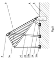
- Fig. 5 presents a side view on the corner module after unfolding it to the flood barrier position
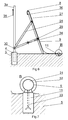
- Fig. 6 presents a view on the straight module of the fence, unfolded outwards, after transforming it into a flood barrier
- Fig. 7 presents a detail of the seal of the barrier unfolded outwards, in the spot where the fence meets the ground.
- the fence subassembly consists of straight frame module 1, unfolded outwards the fence and a corner frame module 2, both equipped with 3a, 3b, 3c load-bearing piles mounted on foundation 4 settled in the ground 5.
- a span 6 is mounted between the 3a, 3b load-bearing piles of this straight 1 frame module.
- Frame modules 1, 1a and 2 are interconnected with a bolt 7.
- Pins 8 are mounted atop frame modules 1, 1a and 2 to support flexible sealing material 9, tightly mounted onto a dedicated sealing fixture 10, 11 founded in the ground 5.
- the load-bearing piles 3a, 3b of the straight frame module 1 unfolded inwards the fence are permanently fixed to the span 6, forming an integral part.
- the load-bearing piles 3c, 3d are divided in the upper 12 and lower part 13, both mounted on rotary hinges on the pivot 14. After folding to the vertical position, they are temporarily connected to one another with a bar 15 equipped with a hole located on the free end of the pile 12 mounted on the upper part.
- the bar is shut off in special sleeves 16a, 16b, mounted on the lower part 13 of the pile, with a staple 17 located in co-axis holes of the bar 15 and the sleeve 16a, 16b.
- the flexible material 9 applied here is fully waterproof, and thus may be mounted on the frame modules 1 and 2 from the flood side. All frame modules 1, 1a and 2 are equipped with sleeves 19 cooperating with corresponding bolts 7. The lower part of the flexible material 9 is mounted in the base, at ground level 5, using a flexible roller 18 locked in a special fixture 10.
- the corner 2 frame module is, in general, divided according to its diagonal, whereas its hinged span 20 is mounted on a fixed span 21 using suitable hinges 22. After unfolding to the flood position, the hinged span 20 rests on supports 23, 23a locked in support sockets 24, 24a. After unfolding to the flood position, the corner 1a frame module rests on the ground 5, propped by a support 25 locked in a support socket 26.
- the straight frame module 1 unfolded outwards the fence is equipped with load-bearing piles 3a, 3b, on which a hinged span 27 is suspended.
- the load-bearing piles 3a, 3b are connected to the span 27 with a support 28 and a bar 29, both mounted on pivots 30 permanently fixed to the load-bearing piles 3a, 3b.
- the lower edge of the flexible material 9 is tied around the bar 31 near the ground 5, and then enclosed with a flexible band 32.
- the bar 31 is fixed using dedicated ties 33 to a special curb 11 founded in the ground 5.
- the bar 29 is grabbed by a support 28, plus the bar 29 is equipped with a joint 34.
- the load-bearing piles 3a, 3b of this module are equipped with bolts 35 cooperating with sleeves 36 mounted on the span 27.
Landscapes
- Engineering & Computer Science (AREA)
- General Engineering & Computer Science (AREA)
- Civil Engineering (AREA)
- Structural Engineering (AREA)
- Architecture (AREA)
- Environmental & Geological Engineering (AREA)
- Ocean & Marine Engineering (AREA)
- Mechanical Engineering (AREA)
- Revetment (AREA)
- Devices Affording Protection Of Roads Or Walls For Sound Insulation (AREA)
- Fencing (AREA)
Abstract
Description
- The subject of this invention is a modular, double-function subassembly which, placed in the vertical position, serves as a fence, and which features the option of being transformed into a flood barrier, after unfolding it.
- Polish patent description no.
PL199 371 - The essence of this invention is that it consists of a straight frame module unfolded outwards the fence and a corner frame module, both equipped with load-bearing piles mounted on the foundation slab settled in the ground. A span is mounted between the load-bearing piles of this straight frame module. Particular frame modules are interconnected with a bolt. Pins are mounted atop frame modules to support flexible sealing material, tightly mounted onto a dedicated sealing fixture founded in the ground.
- In another variant of the invention, the load-bearing piles of the straight, frame module unfolded inwards the fence are permanently fixed to the span, forming an integral part. The load-bearing piles are divided in the upper and lower part, both mounted on rotary hinges on the pivot. After folding to the vertical position, they are temporarily connected to one another with a bar equipped with a hole located on the free end of the pile mounted on the upper part. The bar is shut off in special sleeves, mounted on the lower part of the pile, with a staple located in co-axis holes of the bar and the sleeve. The flexible material applied here is fully waterproof, and thus may be mounted on the frame modules from the flood side. All frame modules are equipped with sleeves cooperating with corresponding bolts. The lower part of the flexible material is mounted in the base, at ground level, using a flexible roller locked in a special fixture.
- The corner frame module is, in general, divided according to its diagonal, whereas its hinged span is mounted in a fixed span using suitable hinges. After unfolding to the flood position, the hinged span rests on supports locked in support sockets. After unfolding to the flood position, the corner frame module rests on the ground, propped by a support locked in a support socket.
- The straight frame module unfolded outwards the fence is equipped with load-bearing piles, on which a hinged span is suspended. The load-bearing piles are connected to the span with a support and a bar, both mounted on pivots permanently fixed to the load-bearing piles. The lower edge of the flexible material is tied around the bar, and then enclosed with a flexible band. The bar is fixed using dedicated ties to a special curb founded in the ground. After folding the span to the vertical position, the bar is grabbed by a support, plus it is equipped with a joint. The load-bearing piles of this module are equipped with bolts cooperating with sleeves mounted on the span.
- The solution featured in the invention allows for eliminating the costs of logistics and the costs of storing classic flood barriers in dedicated, specially suited spaces. In the event of a flood, buildings and facilities are not secured by bags filled with sand, which has positive effect on the natural environment. The fact that transforming the fence into a flood barrier requires only bending the spans and applying a water-resistant, flexible material, easily sealed onto the ground allows for adapting the fence to the flood barrier function in the very first stage of a flood threat situation.
- The joint system used with the bar allows for easy unfolding of the fence and transforming it into a flood barrier.
- When executed according to the specifications of the invention, the fence performs its utilitarian function for the entire duration of its life span. In a flood threat situation, the fence can be easily transformed to perform the function of a flood barrier.
- The load-bearing piles applied in the fence, opened ajar together with frame modules allow for unfolding the fence inwards in transforming it into a flood barrier. The result is rational use of land area, without the need to leave an outer strip of land for unfolding a fence, the segments of which unfold in the outward direction.
- The subject of the invention is presented on an example in the figures, in which
Fig. 1 presents a front view of the straight frame module unfolded outwards the fence and the corner frame module,Fig. 2 presents a front view of the straight frame module unfolded inwards the frame and the corner frame module,Fig. 3 presents a side view on the straight module unfolded inwards the fence to the flood barrier position,Fig. 4 presents a detail of the rotary connection of two load-bearing piles as well as a detail of the sealed connection of the spot where the barrier joins the ground,Fig. 5 presents a side view on the corner module after unfolding it to the flood barrier position,Fig. 6 presents a view on the straight module of the fence, unfolded outwards, after transforming it into a flood barrier, andFig. 7 presents a detail of the seal of the barrier unfolded outwards, in the spot where the fence meets the ground. - According to the invention, the fence subassembly consists of straight frame module 1, unfolded outwards the fence and a
corner frame module 2, both equipped with 3a, 3b, 3c load-bearing piles mounted onfoundation 4 settled in theground 5. Aspan 6 is mounted between the 3a, 3b load-bearing piles of this straight 1 frame module.Frame modules bolt 7.Pins 8 are mounted atopframe modules flexible sealing material 9, tightly mounted onto adedicated sealing fixture ground 5. - In another variant of the invention, the load-bearing
piles span 6, forming an integral part. The load-bearingpiles lower part 13, both mounted on rotary hinges on thepivot 14. After folding to the vertical position, they are temporarily connected to one another with abar 15 equipped with a hole located on the free end of thepile 12 mounted on the upper part. The bar is shut off inspecial sleeves lower part 13 of the pile, with astaple 17 located in co-axis holes of thebar 15 and thesleeve flexible material 9 applied here is fully waterproof, and thus may be mounted on theframe modules 1 and 2 from the flood side. Allframe modules sleeves 19 cooperating withcorresponding bolts 7. The lower part of theflexible material 9 is mounted in the base, atground level 5, using aflexible roller 18 locked in aspecial fixture 10. - The
corner 2 frame module is, in general, divided according to its diagonal, whereas itshinged span 20 is mounted on afixed span 21 usingsuitable hinges 22. After unfolding to the flood position, thehinged span 20 rests onsupports support sockets corner 1a frame module rests on theground 5, propped by asupport 25 locked in asupport socket 26. - The straight frame module 1 unfolded outwards the fence is equipped with load-bearing
piles hinged span 27 is suspended. The load-bearingpiles span 27 with asupport 28 and abar 29, both mounted onpivots 30 permanently fixed to the load-bearingpiles flexible material 9 is tied around thebar 31 near theground 5, and then enclosed with aflexible band 32. Thebar 31 is fixed usingdedicated ties 33 to aspecial curb 11 founded in theground 5. After folding thespan 6 to the vertical position, thebar 29 is grabbed by asupport 28, plus thebar 29 is equipped with ajoint 34. The load-bearingpiles bolts 35 cooperating withsleeves 36 mounted on thespan 27.
Claims (10)
- The fence subassembly with the option of being transformed into a flood barrier, equipped with load-bearing elements, modules and spans, characterized in that it consists of the straight frame module (1, 1a) and the corner frame module (2) equipped with load-bearing piles (3a, 3b, 3c) mounted on a foundation (4) settled in the ground (5). A span (6) is mounted between the load-bearing piles (3a, 3b) of this straight (1) frame module, whereas frame modules (1, 1a) and (2) are interconnected with a bolt (7). Pins (8) are mounted atop frame modules (1, 1a) and (2) to support flexible sealing material (9) tightly mounted onto a dedicated sealing fixture (10, 11) founded in the ground (5).
- The fence subassembly according to claim 1 characterized in that load-bearing piles (3a, 3b) of the straight (1) frame module are permanently fixed to the span (6), forming an integral part, as the straight (1a) frame module, whereas the load-bearing piles (3c, 3d) are divided in the upper (12) and lower (13) part, both mounted on rotary hinges on the pivot (14). After folding to the vertical position, they are temporarily connected to one another with a bar (15) equipped with a hole located on the free end of the pile (12) mounted on the upper part and shut off in special sleeves (16a, 16b), mounted on the lower part (13) of the pile, with a staple (17) located in co-axis holes of the bar (15) and the sleeve (16a, 16b).
- The fence subassembly according to claim 1 characterized in that the flexible material (9) is water-resistant and mounted to frame modules (1) and (2) from the flood side.
- The fence subassembly according to claim 1 characterized in that frame modules (1, 1a) and (2) are equipped with sleeves (19) cooperating with corresponding bolts (7).
- The fence subassembly according to claim 1 or 2 characterized in that the lower edge of the flexible material (9) is mounted near the ground (5) with a flexible roller (18) locked in a special fixture (10).
- The fence subassembly according to claim 1 or 2 characterized in that the corner frame module (2) is, in general, divided according to its diagonal, whereas its hinged span (20) is mounted in a fixed span (21) using suitable hinges (22), and after unfolding to the flood position, the hinged span (20) rests on supports (23, 23a) locked in support sockets (24, 24a). After unfolding to the flood position, the corner frame module (1a) rests on the ground (5), propped by a support (25) locked in a support socket (26).
- The fence subassembly according to claim 1 characterized in that the frame module (1) is equipped with load-bearing piles (3a, 3b), on which a hinged span (27) is suspended, whereas the load-bearing piles (3a, 3b) are connected to the span (27) with a support (28) and a bar (29), both mounted on pivots (30) permanently fixed to the load-bearing piles (3a, 3b), and the lower edge of the flexible material (9) is tied around the bar (31) near the ground (5), and then enclosed with a flexible band (32), whereas the bar (31) is fixed using dedicated ties (33) to a special curb (11) founded in the ground (5).
- The fence subassembly according to claim 1 or 7 characterized in that after folding the span (6) to the vertical position, the bar (29) is grabbed by a support (28).
- The fence subassembly according to claim 1 or 7 characterized in that the bar (29) is equipped with a joint (34).
- The fence subassembly according to claim 1 or 7 characterized in that the load-bearing piles (3a, 3b) are equipped with bolts (35) cooperating with sleeves (36) mounted on the span (27).
Applications Claiming Priority (2)
| Application Number | Priority Date | Filing Date | Title |
|---|---|---|---|
| PL403490A PL403490A1 (en) | 2013-04-10 | 2013-04-10 | Segment fence with the ability to transform the barrier fence in the dam flood control |
| PL404925A PL404925A1 (en) | 2013-07-31 | 2013-07-31 | Fence subassembly with the option of converting it into a flood barrier |
Publications (3)
| Publication Number | Publication Date |
|---|---|
| EP2789775A2 true EP2789775A2 (en) | 2014-10-15 |
| EP2789775A3 EP2789775A3 (en) | 2015-03-11 |
| EP2789775B1 EP2789775B1 (en) | 2016-07-06 |
Family
ID=49223714
Family Applications (1)
| Application Number | Title | Priority Date | Filing Date |
|---|---|---|---|
| EP13460052.7A Not-in-force EP2789775B1 (en) | 2013-04-10 | 2013-08-02 | Fencing subassembly with the option of being transformed into a flood barrier |
Country Status (1)
| Country | Link |
|---|---|
| EP (1) | EP2789775B1 (en) |
Families Citing this family (1)
| Publication number | Priority date | Publication date | Assignee | Title |
|---|---|---|---|---|
| CN106593076A (en) * | 2015-10-15 | 2017-04-26 | 江苏爱福特科技开发有限公司 | Water injection fence |
Citations (1)
| Publication number | Priority date | Publication date | Assignee | Title |
|---|---|---|---|---|
| PL199371B1 (en) | 2001-03-16 | 2008-09-30 | Aquafence As | Portable flood barrier section and flood barrier |
Family Cites Families (3)
| Publication number | Priority date | Publication date | Assignee | Title |
|---|---|---|---|---|
| DE20302069U1 (en) * | 2003-02-05 | 2004-04-29 | Nezirovic, Fikret | Demountable flood protection barrier has a demountable support structure for a modular wall supported on permanent ground fittings |
| US7815397B1 (en) * | 2009-08-12 | 2010-10-19 | Chen-Yuan Dung | Expansion-sealed flood control gate |
| DE102010046504A1 (en) * | 2010-09-24 | 2012-03-29 | Hartmut Wibbeler | Flood protection wall |
-
2013
- 2013-08-02 EP EP13460052.7A patent/EP2789775B1/en not_active Not-in-force
Patent Citations (1)
| Publication number | Priority date | Publication date | Assignee | Title |
|---|---|---|---|---|
| PL199371B1 (en) | 2001-03-16 | 2008-09-30 | Aquafence As | Portable flood barrier section and flood barrier |
Also Published As
| Publication number | Publication date |
|---|---|
| EP2789775B1 (en) | 2016-07-06 |
| EP2789775A3 (en) | 2015-03-11 |
Similar Documents
| Publication | Publication Date | Title |
|---|---|---|
| CN104736768B (en) | blocking device | |
| BRPI0719354A2 (en) | FOLDING INDOOR | |
| US11008134B2 (en) | Foldable and/or collapsible plastic/composite utility enclosures | |
| RU2632912C2 (en) | Mobile barrier flood protection system | |
| CN1255177A (en) | Damming device for creating a liquid-retaining protective embankment | |
| WO2014155034A1 (en) | A shuttering support and related system | |
| RS64599B1 (en) | Mobile flood prevention system | |
| EP2789775A2 (en) | Fencing subassembly with the option of being transformed into a flood barrier | |
| CN104428476A (en) | flood control equipment | |
| US20160230362A1 (en) | Flood defence barriers and methods of erecting flood defence barriers | |
| SE0702093L (en) | container structure | |
| DE202008012907U1 (en) | Arrangement for the temporary protection of structures against flooding | |
| JP2020190076A (en) | Assembling method for assembling type buried box jigs such as handholes and manholes and assembling type buried box using the jig | |
| GB2533944A (en) | A modular building support apparatus | |
| AU2016267390A1 (en) | Fluid storage apparatus | |
| EP3034772B1 (en) | Sealing device of an opening for protecting against flooding | |
| RU2396390C1 (en) | Device for repair of hydraulic facilities | |
| BR102015009644A2 (en) | Container with sequential assembly and finishing system for building a house | |
| WO2003069072A1 (en) | Equipment for protecting buildings against flooding | |
| WO2015026220A2 (en) | Prefabricated modular dwelling | |
| US20190178027A1 (en) | Adjustable Flood Barrier Assembly | |
| DE20102852U1 (en) | Plate system | |
| CN216476461U (en) | A protective flap for outside corners | |
| CN208637997U (en) | A buried pipeline protection device | |
| EP1738050B1 (en) | Protective wall in particular high water protective wall |
Legal Events
| Date | Code | Title | Description |
|---|---|---|---|
| PUAI | Public reference made under article 153(3) epc to a published international application that has entered the european phase |
Free format text: ORIGINAL CODE: 0009012 |
|
| 17P | Request for examination filed |
Effective date: 20130802 |
|
| AK | Designated contracting states |
Kind code of ref document: A2 Designated state(s): AL AT BE BG CH CY CZ DE DK EE ES FI FR GB GR HR HU IE IS IT LI LT LU LV MC MK MT NL NO PL PT RO RS SE SI SK SM TR |
|
| AX | Request for extension of the european patent |
Extension state: BA ME |
|
| PUAL | Search report despatched |
Free format text: ORIGINAL CODE: 0009013 |
|
| AK | Designated contracting states |
Kind code of ref document: A3 Designated state(s): AL AT BE BG CH CY CZ DE DK EE ES FI FR GB GR HR HU IE IS IT LI LT LU LV MC MK MT NL NO PL PT RO RS SE SI SK SM TR |
|
| AX | Request for extension of the european patent |
Extension state: BA ME |
|
| RIC1 | Information provided on ipc code assigned before grant |
Ipc: E04H 9/14 20060101AFI20150203BHEP Ipc: E04H 17/16 20060101ALI20150203BHEP Ipc: E02B 3/10 20060101ALI20150203BHEP |
|
| R17P | Request for examination filed (corrected) |
Effective date: 20150825 |
|
| RBV | Designated contracting states (corrected) |
Designated state(s): AL AT BE BG CH CY CZ DE DK EE ES FI FR GB GR HR HU IE IS IT LI LT LU LV MC MK MT NL NO PL PT RO RS SE SI SK SM TR |
|
| GRAP | Despatch of communication of intention to grant a patent |
Free format text: ORIGINAL CODE: EPIDOSNIGR1 |
|
| INTG | Intention to grant announced |
Effective date: 20151208 |
|
| GRAS | Grant fee paid |
Free format text: ORIGINAL CODE: EPIDOSNIGR3 |
|
| GRAA | (expected) grant |
Free format text: ORIGINAL CODE: 0009210 |
|
| AK | Designated contracting states |
Kind code of ref document: B1 Designated state(s): AL AT BE BG CH CY CZ DE DK EE ES FI FR GB GR HR HU IE IS IT LI LT LU LV MC MK MT NL NO PL PT RO RS SE SI SK SM TR |
|
| REG | Reference to a national code |
Ref country code: GB Ref legal event code: FG4D |
|
| REG | Reference to a national code |
Ref country code: AT Ref legal event code: REF Ref document number: 810842 Country of ref document: AT Kind code of ref document: T Effective date: 20160715 Ref country code: CH Ref legal event code: EP |
|
| REG | Reference to a national code |
Ref country code: IE Ref legal event code: FG4D |
|
| REG | Reference to a national code |
Ref country code: DE Ref legal event code: R096 Ref document number: 602013009102 Country of ref document: DE |
|
| REG | Reference to a national code |
Ref country code: NL Ref legal event code: MP Effective date: 20160706 |
|
| REG | Reference to a national code |
Ref country code: LT Ref legal event code: MG4D |
|
| REG | Reference to a national code |
Ref country code: AT Ref legal event code: MK05 Ref document number: 810842 Country of ref document: AT Kind code of ref document: T Effective date: 20160706 |
|
| PG25 | Lapsed in a contracting state [announced via postgrant information from national office to epo] |
Ref country code: BE Free format text: LAPSE BECAUSE OF NON-PAYMENT OF DUE FEES Effective date: 20160831 |
|
| PG25 | Lapsed in a contracting state [announced via postgrant information from national office to epo] |
Ref country code: NL Free format text: LAPSE BECAUSE OF FAILURE TO SUBMIT A TRANSLATION OF THE DESCRIPTION OR TO PAY THE FEE WITHIN THE PRESCRIBED TIME-LIMIT Effective date: 20160706 Ref country code: FI Free format text: LAPSE BECAUSE OF FAILURE TO SUBMIT A TRANSLATION OF THE DESCRIPTION OR TO PAY THE FEE WITHIN THE PRESCRIBED TIME-LIMIT Effective date: 20160706 Ref country code: IT Free format text: LAPSE BECAUSE OF FAILURE TO SUBMIT A TRANSLATION OF THE DESCRIPTION OR TO PAY THE FEE WITHIN THE PRESCRIBED TIME-LIMIT Effective date: 20160706 Ref country code: NO Free format text: LAPSE BECAUSE OF FAILURE TO SUBMIT A TRANSLATION OF THE DESCRIPTION OR TO PAY THE FEE WITHIN THE PRESCRIBED TIME-LIMIT Effective date: 20161006 Ref country code: RS Free format text: LAPSE BECAUSE OF FAILURE TO SUBMIT A TRANSLATION OF THE DESCRIPTION OR TO PAY THE FEE WITHIN THE PRESCRIBED TIME-LIMIT Effective date: 20160706 Ref country code: HR Free format text: LAPSE BECAUSE OF FAILURE TO SUBMIT A TRANSLATION OF THE DESCRIPTION OR TO PAY THE FEE WITHIN THE PRESCRIBED TIME-LIMIT Effective date: 20160706 Ref country code: LT Free format text: LAPSE BECAUSE OF FAILURE TO SUBMIT A TRANSLATION OF THE DESCRIPTION OR TO PAY THE FEE WITHIN THE PRESCRIBED TIME-LIMIT Effective date: 20160706 Ref country code: IS Free format text: LAPSE BECAUSE OF FAILURE TO SUBMIT A TRANSLATION OF THE DESCRIPTION OR TO PAY THE FEE WITHIN THE PRESCRIBED TIME-LIMIT Effective date: 20161106 |
|
| PG25 | Lapsed in a contracting state [announced via postgrant information from national office to epo] |
Ref country code: PL Free format text: LAPSE BECAUSE OF FAILURE TO SUBMIT A TRANSLATION OF THE DESCRIPTION OR TO PAY THE FEE WITHIN THE PRESCRIBED TIME-LIMIT Effective date: 20160706 Ref country code: BE Free format text: LAPSE BECAUSE OF FAILURE TO SUBMIT A TRANSLATION OF THE DESCRIPTION OR TO PAY THE FEE WITHIN THE PRESCRIBED TIME-LIMIT Effective date: 20160706 Ref country code: GR Free format text: LAPSE BECAUSE OF FAILURE TO SUBMIT A TRANSLATION OF THE DESCRIPTION OR TO PAY THE FEE WITHIN THE PRESCRIBED TIME-LIMIT Effective date: 20161007 Ref country code: SE Free format text: LAPSE BECAUSE OF FAILURE TO SUBMIT A TRANSLATION OF THE DESCRIPTION OR TO PAY THE FEE WITHIN THE PRESCRIBED TIME-LIMIT Effective date: 20160706 Ref country code: AT Free format text: LAPSE BECAUSE OF FAILURE TO SUBMIT A TRANSLATION OF THE DESCRIPTION OR TO PAY THE FEE WITHIN THE PRESCRIBED TIME-LIMIT Effective date: 20160706 Ref country code: PT Free format text: LAPSE BECAUSE OF FAILURE TO SUBMIT A TRANSLATION OF THE DESCRIPTION OR TO PAY THE FEE WITHIN THE PRESCRIBED TIME-LIMIT Effective date: 20161107 Ref country code: ES Free format text: LAPSE BECAUSE OF FAILURE TO SUBMIT A TRANSLATION OF THE DESCRIPTION OR TO PAY THE FEE WITHIN THE PRESCRIBED TIME-LIMIT Effective date: 20160706 Ref country code: LV Free format text: LAPSE BECAUSE OF FAILURE TO SUBMIT A TRANSLATION OF THE DESCRIPTION OR TO PAY THE FEE WITHIN THE PRESCRIBED TIME-LIMIT Effective date: 20160706 |
|
| REG | Reference to a national code |
Ref country code: DE Ref legal event code: R119 Ref document number: 602013009102 Country of ref document: DE |
|
| REG | Reference to a national code |
Ref country code: CH Ref legal event code: PL |
|
| PG25 | Lapsed in a contracting state [announced via postgrant information from national office to epo] |
Ref country code: EE Free format text: LAPSE BECAUSE OF FAILURE TO SUBMIT A TRANSLATION OF THE DESCRIPTION OR TO PAY THE FEE WITHIN THE PRESCRIBED TIME-LIMIT Effective date: 20160706 Ref country code: MC Free format text: LAPSE BECAUSE OF FAILURE TO SUBMIT A TRANSLATION OF THE DESCRIPTION OR TO PAY THE FEE WITHIN THE PRESCRIBED TIME-LIMIT Effective date: 20160706 Ref country code: LI Free format text: LAPSE BECAUSE OF NON-PAYMENT OF DUE FEES Effective date: 20160831 Ref country code: RO Free format text: LAPSE BECAUSE OF FAILURE TO SUBMIT A TRANSLATION OF THE DESCRIPTION OR TO PAY THE FEE WITHIN THE PRESCRIBED TIME-LIMIT Effective date: 20160706 Ref country code: CH Free format text: LAPSE BECAUSE OF NON-PAYMENT OF DUE FEES Effective date: 20160831 |
|
| PLBE | No opposition filed within time limit |
Free format text: ORIGINAL CODE: 0009261 |
|
| STAA | Information on the status of an ep patent application or granted ep patent |
Free format text: STATUS: NO OPPOSITION FILED WITHIN TIME LIMIT |
|
| REG | Reference to a national code |
Ref country code: FR Ref legal event code: ST Effective date: 20170428 |
|
| PG25 | Lapsed in a contracting state [announced via postgrant information from national office to epo] |
Ref country code: SM Free format text: LAPSE BECAUSE OF FAILURE TO SUBMIT A TRANSLATION OF THE DESCRIPTION OR TO PAY THE FEE WITHIN THE PRESCRIBED TIME-LIMIT Effective date: 20160706 Ref country code: CZ Free format text: LAPSE BECAUSE OF FAILURE TO SUBMIT A TRANSLATION OF THE DESCRIPTION OR TO PAY THE FEE WITHIN THE PRESCRIBED TIME-LIMIT Effective date: 20160706 Ref country code: BG Free format text: LAPSE BECAUSE OF FAILURE TO SUBMIT A TRANSLATION OF THE DESCRIPTION OR TO PAY THE FEE WITHIN THE PRESCRIBED TIME-LIMIT Effective date: 20161006 Ref country code: SK Free format text: LAPSE BECAUSE OF FAILURE TO SUBMIT A TRANSLATION OF THE DESCRIPTION OR TO PAY THE FEE WITHIN THE PRESCRIBED TIME-LIMIT Effective date: 20160706 Ref country code: DK Free format text: LAPSE BECAUSE OF FAILURE TO SUBMIT A TRANSLATION OF THE DESCRIPTION OR TO PAY THE FEE WITHIN THE PRESCRIBED TIME-LIMIT Effective date: 20160706 |
|
| REG | Reference to a national code |
Ref country code: IE Ref legal event code: MM4A |
|
| 26N | No opposition filed |
Effective date: 20170407 |
|
| PG25 | Lapsed in a contracting state [announced via postgrant information from national office to epo] |
Ref country code: IE Free format text: LAPSE BECAUSE OF NON-PAYMENT OF DUE FEES Effective date: 20160802 Ref country code: DE Free format text: LAPSE BECAUSE OF NON-PAYMENT OF DUE FEES Effective date: 20170301 Ref country code: FR Free format text: LAPSE BECAUSE OF NON-PAYMENT OF DUE FEES Effective date: 20160906 |
|
| PG25 | Lapsed in a contracting state [announced via postgrant information from national office to epo] |
Ref country code: SI Free format text: LAPSE BECAUSE OF FAILURE TO SUBMIT A TRANSLATION OF THE DESCRIPTION OR TO PAY THE FEE WITHIN THE PRESCRIBED TIME-LIMIT Effective date: 20160706 Ref country code: LU Free format text: LAPSE BECAUSE OF NON-PAYMENT OF DUE FEES Effective date: 20160802 |
|
| GBPC | Gb: european patent ceased through non-payment of renewal fee |
Effective date: 20170802 |
|
| PG25 | Lapsed in a contracting state [announced via postgrant information from national office to epo] |
Ref country code: HU Free format text: LAPSE BECAUSE OF FAILURE TO SUBMIT A TRANSLATION OF THE DESCRIPTION OR TO PAY THE FEE WITHIN THE PRESCRIBED TIME-LIMIT; INVALID AB INITIO Effective date: 20130802 |
|
| PG25 | Lapsed in a contracting state [announced via postgrant information from national office to epo] |
Ref country code: MK Free format text: LAPSE BECAUSE OF FAILURE TO SUBMIT A TRANSLATION OF THE DESCRIPTION OR TO PAY THE FEE WITHIN THE PRESCRIBED TIME-LIMIT Effective date: 20160706 Ref country code: CY Free format text: LAPSE BECAUSE OF FAILURE TO SUBMIT A TRANSLATION OF THE DESCRIPTION OR TO PAY THE FEE WITHIN THE PRESCRIBED TIME-LIMIT Effective date: 20160706 Ref country code: MT Free format text: LAPSE BECAUSE OF NON-PAYMENT OF DUE FEES Effective date: 20160831 |
|
| PG25 | Lapsed in a contracting state [announced via postgrant information from national office to epo] |
Ref country code: GB Free format text: LAPSE BECAUSE OF NON-PAYMENT OF DUE FEES Effective date: 20170802 |
|
| PG25 | Lapsed in a contracting state [announced via postgrant information from national office to epo] |
Ref country code: AL Free format text: LAPSE BECAUSE OF FAILURE TO SUBMIT A TRANSLATION OF THE DESCRIPTION OR TO PAY THE FEE WITHIN THE PRESCRIBED TIME-LIMIT Effective date: 20160706 Ref country code: TR Free format text: LAPSE BECAUSE OF FAILURE TO SUBMIT A TRANSLATION OF THE DESCRIPTION OR TO PAY THE FEE WITHIN THE PRESCRIBED TIME-LIMIT Effective date: 20160706 |