EP2789525A1 - Steering device - Google Patents
Steering device Download PDFInfo
- Publication number
- EP2789525A1 EP2789525A1 EP12855629.7A EP12855629A EP2789525A1 EP 2789525 A1 EP2789525 A1 EP 2789525A1 EP 12855629 A EP12855629 A EP 12855629A EP 2789525 A1 EP2789525 A1 EP 2789525A1
- Authority
- EP
- European Patent Office
- Prior art keywords
- pinion
- housing
- shaft
- rack
- angle
- Prior art date
- Legal status (The legal status is an assumption and is not a legal conclusion. Google has not performed a legal analysis and makes no representation as to the accuracy of the status listed.)
- Granted
Links
Images



Classifications
-
- B—PERFORMING OPERATIONS; TRANSPORTING
- B62—LAND VEHICLES FOR TRAVELLING OTHERWISE THAN ON RAILS
- B62D—MOTOR VEHICLES; TRAILERS
- B62D3/00—Steering gears
- B62D3/02—Steering gears mechanical
- B62D3/12—Steering gears mechanical of rack-and-pinion type
-
- B—PERFORMING OPERATIONS; TRANSPORTING
- B62—LAND VEHICLES FOR TRAVELLING OTHERWISE THAN ON RAILS
- B62D—MOTOR VEHICLES; TRAILERS
- B62D5/00—Power-assisted or power-driven steering
- B62D5/04—Power-assisted or power-driven steering electrical, e.g. using an electric servo-motor connected to, or forming part of, the steering gear
- B62D5/0409—Electric motor acting on the steering column
-
- F—MECHANICAL ENGINEERING; LIGHTING; HEATING; WEAPONS; BLASTING
- F16—ENGINEERING ELEMENTS AND UNITS; GENERAL MEASURES FOR PRODUCING AND MAINTAINING EFFECTIVE FUNCTIONING OF MACHINES OR INSTALLATIONS; THERMAL INSULATION IN GENERAL
- F16C—SHAFTS; FLEXIBLE SHAFTS; ELEMENTS OR CRANKSHAFT MECHANISMS; ROTARY BODIES OTHER THAN GEARING ELEMENTS; BEARINGS
- F16C35/00—Rigid support of bearing units; Housings, e.g. caps, covers
- F16C35/04—Rigid support of bearing units; Housings, e.g. caps, covers in the case of ball or roller bearings
- F16C35/06—Mounting or dismounting of ball or roller bearings; Fixing them onto shaft or in housing
- F16C35/067—Fixing them in a housing
-
- F—MECHANICAL ENGINEERING; LIGHTING; HEATING; WEAPONS; BLASTING
- F16—ENGINEERING ELEMENTS AND UNITS; GENERAL MEASURES FOR PRODUCING AND MAINTAINING EFFECTIVE FUNCTIONING OF MACHINES OR INSTALLATIONS; THERMAL INSULATION IN GENERAL
- F16H—GEARING
- F16H57/00—General details of gearing
- F16H57/02—Gearboxes; Mounting gearing therein
- F16H57/028—Gearboxes; Mounting gearing therein characterised by means for reducing vibration or noise
-
- F—MECHANICAL ENGINEERING; LIGHTING; HEATING; WEAPONS; BLASTING
- F16—ENGINEERING ELEMENTS AND UNITS; GENERAL MEASURES FOR PRODUCING AND MAINTAINING EFFECTIVE FUNCTIONING OF MACHINES OR INSTALLATIONS; THERMAL INSULATION IN GENERAL
- F16C—SHAFTS; FLEXIBLE SHAFTS; ELEMENTS OR CRANKSHAFT MECHANISMS; ROTARY BODIES OTHER THAN GEARING ELEMENTS; BEARINGS
- F16C2226/00—Joining parts; Fastening; Assembling or mounting parts
- F16C2226/50—Positive connections
- F16C2226/60—Positive connections with threaded parts, e.g. bolt and nut connections
-
- F—MECHANICAL ENGINEERING; LIGHTING; HEATING; WEAPONS; BLASTING
- F16—ENGINEERING ELEMENTS AND UNITS; GENERAL MEASURES FOR PRODUCING AND MAINTAINING EFFECTIVE FUNCTIONING OF MACHINES OR INSTALLATIONS; THERMAL INSULATION IN GENERAL
- F16C—SHAFTS; FLEXIBLE SHAFTS; ELEMENTS OR CRANKSHAFT MECHANISMS; ROTARY BODIES OTHER THAN GEARING ELEMENTS; BEARINGS
- F16C2326/00—Articles relating to transporting
- F16C2326/20—Land vehicles
- F16C2326/24—Steering systems, e.g. steering rods or columns
-
- F—MECHANICAL ENGINEERING; LIGHTING; HEATING; WEAPONS; BLASTING
- F16—ENGINEERING ELEMENTS AND UNITS; GENERAL MEASURES FOR PRODUCING AND MAINTAINING EFFECTIVE FUNCTIONING OF MACHINES OR INSTALLATIONS; THERMAL INSULATION IN GENERAL
- F16H—GEARING
- F16H19/00—Gearings comprising essentially only toothed gears or friction members and not capable of conveying indefinitely-continuing rotary motion
- F16H19/02—Gearings comprising essentially only toothed gears or friction members and not capable of conveying indefinitely-continuing rotary motion for interconverting rotary or oscillating motion and reciprocating motion
- F16H19/04—Gearings comprising essentially only toothed gears or friction members and not capable of conveying indefinitely-continuing rotary motion for interconverting rotary or oscillating motion and reciprocating motion comprising a rack
-
- F—MECHANICAL ENGINEERING; LIGHTING; HEATING; WEAPONS; BLASTING
- F16—ENGINEERING ELEMENTS AND UNITS; GENERAL MEASURES FOR PRODUCING AND MAINTAINING EFFECTIVE FUNCTIONING OF MACHINES OR INSTALLATIONS; THERMAL INSULATION IN GENERAL
- F16H—GEARING
- F16H55/00—Elements with teeth or friction surfaces for conveying motion; Worms, pulleys or sheaves for gearing mechanisms
- F16H55/02—Toothed members; Worms
- F16H55/26—Racks
- F16H55/28—Special devices for taking up backlash
- F16H55/283—Special devices for taking up backlash using pressure yokes
-
- F—MECHANICAL ENGINEERING; LIGHTING; HEATING; WEAPONS; BLASTING
- F16—ENGINEERING ELEMENTS AND UNITS; GENERAL MEASURES FOR PRODUCING AND MAINTAINING EFFECTIVE FUNCTIONING OF MACHINES OR INSTALLATIONS; THERMAL INSULATION IN GENERAL
- F16H—GEARING
- F16H57/00—General details of gearing
- F16H57/02—Gearboxes; Mounting gearing therein
- F16H57/021—Shaft support structures, e.g. partition walls, bearing eyes, casing walls or covers with bearings
Definitions
- Fixing the bearing by a ring nut is preferred in increasing the rigidity of the bearing with respect to the radial direction and the thrust direction.
- this leads to the problem of increase in the size of the steering gear assembly, because a space for accommodating the ring nut is needed.
- An object of the present invention is to provide a rack-and-pinion type steering apparatus in which abnormal noise that might be caused when the position of engagement of a pinion and rack teeth is displaced due to a load acting on the pinion shaft is prevented from occurring without an increase in the manufacturing cost.
Landscapes
- Engineering & Computer Science (AREA)
- General Engineering & Computer Science (AREA)
- Mechanical Engineering (AREA)
- Chemical & Material Sciences (AREA)
- Combustion & Propulsion (AREA)
- Transportation (AREA)
- Transmission Devices (AREA)
- Power Steering Mechanism (AREA)
Abstract
Description
- The present invention relates to a steering apparatus, in particular, a rack-and-pinion type steering apparatus adapted to prevent abnormal noise from being generated when a gap is created between an outer ring of a bearing fixed by a tapered snap ring and a housing by a load exerted on a pinion shaft.
- In rack-and-pinion type steering apparatuses, a rack shaft that changes the turning angle of wheels via a tie rod is supported on the housing of the steering gear assembly in such a way as to be able to move back and forth, and a pinion shaft that transmits the rotation of the steering wheel to the rack shaft is rotatably supported on the housing by a bearing.
- In such rack-and-pinion type steering apparatus, the pinion shaft may move in the radial direction or in the thrust direction due to a load exerted on the pinion shaft upon steering operation, whereby abnormal noise is generated or the steering force is varied. In view of this, the bearing with which the pinion shaft is rotatably supported is fixed to the housing thereby fixing the pinion shaft with respect to the radial direction and the thrust direction to prevent the generation of abnormal noise and the variation in the steering force.
- Fixing the bearing by a ring nut is preferred in increasing the rigidity of the bearing with respect to the radial direction and the thrust direction. However, this leads to the problem of increase in the size of the steering gear assembly, because a space for accommodating the ring nut is needed.
- Preloading the bearing with a tapered snap ring serving as a fastening ring leads to low cost and light weight and allows reduction in the size of the steering gear assembly because the space for accommodating the tapered snap ring may be small. However, fixing the bearing by a tapered snap ring leads to low rigidity of the bearing with respect to the radial direction and the thrust direction.
- Consequently, a load exerted on the pinion shaft upon steering will press the tapered snap ring up in the axial direction or tilt it, whereby the pinion shaft will shift in the thrust direction to create a gap between the outer ring of the bearing and the housing. Then, the position of engagement of the pinion and the rack is displaced from the correct position, causing abnormal noise like slapping noise.
- In a rack-and-pinion type steering apparatus disclosed in Japanese Patent Application Laid-Open No.
2010-038254 2010-038254 - Patent Document: Japanese Patent Application Laid-Open No.
2010-038254 - An object of the present invention is to provide a rack-and-pinion type steering apparatus in which abnormal noise that might be caused when the position of engagement of a pinion and rack teeth is displaced due to a load acting on the pinion shaft is prevented from occurring without an increase in the manufacturing cost.
- The above-described object can be achieved by the following means. According to the present invention, there is provided a steering apparatus comprising a housing; a rack shaft that is supported on the aforementioned housing in such a way as to be able to move back and forth and changes the turning angle of a wheel via a tie rod; a pinion shaft that is linked with a steering wheel, has a pinion engaging with rack teeth of the aforementioned rack shaft, and transmits rotation of the steering wheel to the aforementioned rack shaft; a first bearing that is internally fitted to the aforementioned housing, rotatably supports one end of the aforementioned pinion shaft on the housing, and bears a radial load and a thrust load acting on the aforementioned pinion shaft; a second bearing that is internally fitted to the aforementioned housing, rotatably supports the other end of the aforementioned pinion shaft on the housing, and bears a radial load acting on the aforementioned pinion shaft; and a retaining ring that is internally fitted to an annular groove provided on an inner circumferential surface of the aforementioned housing and has a C-shaped part and an opening defined by two opposed ends of the C-shaped part, the aforementioned C-shaped part being in contact with an end face of an outer ring of the aforementioned first bearing to thereby fix the outer ring of the first bearing to the aforementioned housing, wherein the aforementioned retaining ring is internally fitted to the annular groove of the aforementioned housing in such a way that the aforementioned opening faces toward the aforementioned rack teeth as seen from an axial direction of the aforementioned pinion shaft.
- In a preferred mode of the steering apparatus according to the present invention, as seen from the axial direction of the aforementioned pinion shaft, let θ be the angle of the aforementioned opening relative to a center axis that is parallel to the axis of the aforementioned rack shaft and passes the center of the aforementioned pinion, and let α be a pressure angle of the aforementioned rack teeth; then the range of the aforementioned angle θ is an angle range that is on the rack shaft side among angle ranges delimited by two directions that are inclined respectively from one and the other directions of the aforementioned center axis by angle α about the center of the pinion toward the rack shaft.
- According to the present invention, even when a large moment M acts on the retaining ring by a load exerted on the pinion shaft, tilting of the retaining ring relative to the pinion shaft and displacement of the pinion shaft in the axial direction can be prevented from occurring. In consequence, the position of engagement of the pinion and the rack teeth can be maintained at an appropriate position, and therefore generation of abnormal noise and variation in the steering force can be prevented.
-
-
Fig. 1 is an overall perspective view of a column-assist, rack-and-pinion type steering apparatus according to an embodiment of the present invention. -
Fig. 2 is a longitudinal cross sectional view showing a portion of engagement of a rack and a pinion of a steering gear according to the embodiment of the present invention. -
Fig. 3 is a cross sectional view taken on line III-III ofFig. 2 . -
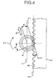
Fig. 4 is a cross sectional view taken on line IV-IV ofFig. 2 , illustrating a load acting on the tooth surface in the portion of engagement of rack teeth and the pinion rotating in the clockwise direction. -
Fig. 5 is a cross sectional view taken on line IV-IV ofFig. 2 , illustrating a load acting on the tooth surface in the portion of engagement of the rack teeth and the pinion rotating in the anticlockwise direction. -
Fig. 1 is an overall perspective view of a column-assist, rack-and-pinion type power steering apparatus according to an embodiment of the present invention. As shown inFig. 1 , the column-assist, rack-and-pinion type power steering apparatus according to the embodiment of the present invention applies a steering assist force generated by amotor 102 attached to a middle portion of asteering column 105 to a steering shaft in order to lighten the hand effort in operating thesteering wheel 101. The rotation of the steering shaft is transmitted to anintermediate shaft 106 to move a rack shaft of a rack-and-pinion typesteering gear assembly 103 back and forth via apinion shaft 107, thereby turning the steer wheels viatie rods 104. -
Fig. 2 is a longitudinal cross sectional view showing the portion of engagement of the rack and the pinion in a steering gear according to the embodiment of the present invention.Fig. 3 is a cross sectional view taken on line III-III ofFig. 2 .Fig. 4 is a cross sectional view taken on line IV-IV ofFig. 2 , illustrating a load acting on the tooth surface in the portion of engagement of rack teeth and the pinion rotating in the clockwise direction.Fig. 5 is a cross sectional view taken on line IV-IV ofFig. 2 , illustrating a load acting on the tooth surface in the portion of engagement of the rack teeth and the pinion rotating in the anticlockwise direction. - The
steering gear assembly 103 according to the embodiment of the present invention is mounted on a frame of a vehicle body such as a front sub-frame, which is not shown in the drawings. Arack shaft 31 is internally fitted in thehousing 21 of thesteering gear assembly 103 in such a way that therack shaft 31 can slide in the vehicle width direction, which is perpendicular to the plane of the drawing sheet ofFig. 2 . Ball joint sockets (not shown) are attached to both ends of therack shaft 31 with respect to the vehicle width direction respectively by screwing, andtie rods 104, 104 (seeFig. 1 ) coupled to the ball joint sockets are connected to wheels via knuckle arms (not shown). - The
pinion shaft 107 has apinion 41 provided in the portion near the lower end. Ashaft portion 42 of thepinion shaft 107 above thepinion 41 is rotatably supported on thehousing 21 via a ball bearing 51, which serves as the first bearing. The ball bearing 51 bears the radial load and the thrust load acting on thepinion shaft 107. Theshaft portion 42 has a diameter smaller than thepinion 41 and is adjacent to thepinion 41 with respect to the vertical direction with a shoulder 44 between them. The portion of thepinion shaft 107 above theshaft portion 42 is provided with agroove 43 extending along its circumference. Aring 52 is fixedly attached to thegroove 43 by caulking. Thering 52 and the shoulder 44 of thepinion shaft 107 hold the inner ring of the ball bearing 51 between them from above and below. - The outer ring of the ball bearing 51 is internally fitted in a
cylindrical bore 22 provided in thehousing 21. The portion of the inner circumferential surface of thecylindrical bore 22 above the ball bearing 51 is provided with anannular groove 23. Atapered snap ring 53 serving as a retaining ring is fitted in theannular groove 23. As shown inFig. 3 , thetapered snap ring 53 has a C-shaped part 532 and an opening 531 defined by two opposed ends of the C-shaped part 532. The upper end face of the outer ring of the ball bearing 51 is pressed downward in the axial direction by the C-shaped part 532 of thetapered snap ring 53, so that the outer ring of the ball bearing 51 is fixed to thehousing 21. Thetapered snap ring 53 is fitted in theannular groove 23 with the C-shaped part 532 being elastically compressed with respect to radial directions. Consequently, a force biasing thetapered snap ring 53 in radially extending directions is always acting on thetapered snap ring 53 in the state in which it is fitted in theannular groove 23. Thetapered snap ring 53 and theannular groove 23 each has at upper side a tapered surface that tapers in such a way that it becomes closer to the ball bearing 51 as it runs radially outward. With the above-described construction, as thetapered snap ring 53 is fitted into theannular groove 23, thetapered snap ring 53 expands in radial directions and presses the outer ring of the ball bearing 51 downward with respect to the axial direction by a wedge effect. In consequence, the gap between the outer ring of the ball bearing 51 and thetapered snap ring 53 and the gap between the outer ring of the ball bearing 51 and the bottom of thecylindrical bore 22 of thehousing 21 are eliminated, and the outer ring of the ball bearing 51 is fixed between thetapered snap ring 53 and the bottom of thecylindrical bore 22 of thehousing 21. - The
shaft portion 45 of thepinion shaft 107 below thepinion 41 is rotatably supported on thehousing 21 via a needle bearing 54, which serves as a second bearing. The needle bearing 54 bears only radial load acting on thepinion shaft 107. The rotation of thepinion shaft 107 is transmitted to therack teeth 32 of therack shaft 31 via thepinion 41 to change the orientation of the steer wheels via thetie rods Fig. 1 coupled to therack shaft 31. - The
housing 21 is provided with a guide bore 24 having a circular cross section and extending in the horizontal direction inFig. 2 or the substantially front-rear direction with respect to the vehicle body. Acylindrical rack guide 61 is internally fitted in the guide bore 24 in such a way that therack guide 61 can slide in the horizontal direction inFig. 2 . Therack guide 61 is provided with a concavecylindrical surface 62 having a curvature substantially equal to the curvature of a convex cylindrical outercircumferential surface 33 of therack shaft 31. The concavecylindrical surface 62 is in contact with the outercircumferential surface 33 of therack shaft 31 to press therack guide 61 against theouter circumference 33 of therack shaft 31. - An adjust
cover 63 is screwed to the right end of the guide bore 24. Acoil spring 64 is provided between the adjustcover 63 and therack guide 61. The adjustcover 63 is turned to appropriately adjust the distance over which it is screwed into the guide bore 24, thereby pressing therack guide 61 toward therack shaft 31 via thecoil spring 64 and pressing therack guide 61 against theouter circumference 33 of therack shaft 31. Thus, backlash in the engagement of thepinion 41 and therack shaft 31 is eliminated to allow smooth movement of therack shaft 31. - A cylindrical
fitting portion 711 at the lower end of a hollowcylindrical cover 71 is press-fitted to the cylindrical bore 22 provided in thehousing 21. Thebottom end face 713 of aflange 712 provided on the upper portion of the cylindricalfitting portion 711 abuts thetop end face 25 of thehousing 21 to position thecover 71 relative to thehousing 21 with respect to the vertical direction. - The
cover 71 extends upward to cover the upper part of thepinion shaft 107. Arubber gasket 72 fixedly attached to the upper end of thecover 71 abuts thetoe board 73 of the vehicle body to prevent the upward displacement of thecover 71. Thegasket 72 absorbs the displacement of thehousing 21 caused by vibration during the running of the vehicle to reduce the impact and prevents dust and foreign matters from entering into the gap between thehousing 21 and thepinion shaft 107. - As the
pinion 41 turns in the clockwise direction as seen from one axial direction of thepinion shaft 107 as indicated byarrow 411 inFig. 4 , the tooth surface of thepinion 41 presses arack tooth 32 in a certain direction in the engaging portion of therack tooth 32 and thepinion 41. The pressing force exerted on therack tooth 32 by the tooth surface of thepinion 41 acts in the direction D1 of the common normal line V1 of the tooth surface of thepinion 41 and therack tooth 32. The common normal line V1 is inclined relative to thepitch line 321 of therack teeth 32 by an angle equal to the pressure angle α of therack teeth 32. In this state, a load acts on the tooth surface of thepinion 41 in the direction opposite to arrow D1. This load acts along the common normal line V1 of the tooth surfaces in the engaging portion. With this load, a load F1 in the direction opposite to arrow D1 acts on thepinion 41 as a whole, as shown inFig. 4 . - On the other hand, as the
pinion 41 turns in the anticlockwise direction as seen from one axial direction of thepinion shaft 107 as indicated byarrow 412 inFig. 5 , the tooth surface of thepinion 41 presses arack tooth 32 in a certain direction in the engaging portion of therack tooth 32 and thepinion 41. The pressing force exerted on therack tooth 32 by the tooth surface of thepinion 41 acts in the direction D2 of the common normal line V2 of the tooth surface of thepinion 41 and therack tooth 32. The common normal line V2 is inclined relative to thepitch line 321 of therack teeth 32 by an angle equal to the pressure angle α of therack teeth 32. In this state, a load acts on the tooth surface of thepinion 41 in the direction opposite to arrow D2. This load acts along the common normal line V2 of the tooth surfaces in the engaging portion. With this load, a load F2 in the direction opposite to arrow D2 acts on thepinion 41 as a whole, as shown inFig. 5 . - As above, the direction of the load acting on the tooth surface in the engaging portion of the
pinion 41 changes depending on the turning direction of thepinion 41. In other words, the direction of the load acting on the pinion as a whole changes between the direction of the above-described load F1 or the direction of the above-described load F2 depending on the turning direction of thepinion 41. As shown inFig. 3 , afirst center axis 47 is defined as a straight line passing thecenter 46 of thepinion 41 and parallel to the axial direction of therack shaft 31 as seen from one axial direction of thepinion shaft 107. Then, the directions of the load F1 and F2 are oriented as follows. The direction of the load F1 is inclined from thecenter axis 47 away from therack shaft 31 on one side of thecenter 46 of thepinion 41 with respect to the vehicle width direction, e.g. on the upper side inFig. 3 , by angle α about thecenter 46 of thepinion 41. On the other hand, the direction of the load F2 is inclined from thecenter axis 47 away from therack shaft 31 on the other side of thecenter 46 of thepinion 41 with respect to the vehicle width direction, e.g. on the lower side inFig. 3 , by angle α about thecenter 46 of thepinion 41. - With the load F1, F2, a bending load that tends to bend the
pinion 41 away from therack shaft 31 acts on thepinion shaft 107, and a bending moment M acts on theball bearing 51 and thetapered snap ring 53 in a substantially upward direction as shown inFig. 2 . In other words, a large moment M acts on the portion of theball bearing 51 and thetapered snap ring 53 on the side opposite to therack shaft 31 as seen from one axial direction of thepinion shaft 107. On the other hand, the effect of the bending moment M on the portion of theball bearing 51 and thetapered snap ring 53 near therack shaft 31 is small. This bending moment M inclines theball bearing 51 and thetapered snap ring 53 relative to the center axis of thepinion shaft 107. The rigidity of the taperedsnap ring 53 is lowest in the portion near theopening 531 and highest in the portion of the C-shaped part 532 that is located at the position opposite to theopening 531, namely at the position having a angle difference of 180 degrees from theopening 531. - As shown in
Fig. 3 , theopening 531 of the taperedsnap ring 53 is fitted to theannular groove 23 at an angle minimizing the effect of the moment M generated by the load F1, F2. Specifically, the taperedsnap ring 53 is fitted to theannular groove 23 in such a way that theopening 531 is located on therack shaft 31 side of thefirst center axis 47 and on asecond center axis 48 passing thecenter 46 of thepinion 41 and perpendicular to thecenter axis 47 as seen from one axial direction of the pinion shaft. - In the embodiment of the present invention, as shown in
Fig. 3 , the angle θ or the angle formed by thecenter axis 47 and the line passing the center of theopening 531 of the taperedsnap ring 53 and thecenter 46 of thepinion 41 is set to 90 degrees. Specifically, theopening 531 is located at a position inclined from thefirst center axis 47 toward therack shaft 31 by 90 degrees about thecenter 46 of thepinion 41, as seen from one axial direction of thepinion shaft 107. Setting the angle θ of theopening 531 relative to thecenter axis 47 to 90 degrees is preferable because the influence of the load F1, F2 on the moment M of the taperedsnap ring 53 is minimized. The angle θ of theopening 531 relative to thecenter axis 47 is not limited to 90 degrees, but it may be set in such a way as to be in a range of angle β shown inFig. 3 or the range expressed by α < θ < (180 degrees - α). More specifically, as seen from one axial direction of thepinion shaft 107, let the angle of the direction of thefirst center axis 47 on one side of the vehicle width direction with respect to thecenter 46 of thepinion 41 be referred to as 0 degree, let the angle inclined from the direction of 0 degree toward therack shaft 31 by 90 degrees be referred to as 90 degrees, and let the angle of the direction of thefirst center axis 47 on the other side of the vehicle width direction be referred to as 180 degrees, then, the range of angle β or the range of θ is the angle range that is closer to therack shaft 31 among the angle ranges delimited by the direction inclined from the direction of 0 degree by angle α toward therack shaft 31 and the direction inclined from the direction of 180 degrees by angle α toward therack shaft 31. In other words, the range of θ is the angle range that is on therack shaft 31 side among the angle ranges delimited by the two directions that are inclined respectively from one and the other directions of thefirst center axis 47 by angle α about thecenter 46 of thepinion 41 toward therack shaft 31. - With the above-described arrangement, even when a large moment M is exerted on the tapered
snap ring 53 by a load F1, F2 acting on thepinion shaft 107 from wheels via therack shaft 31 during running or by a load applied to thepinion shaft 107 during steering, tilting of the taperedsnap ring 53 relative to thepinion shaft 107 and displacement of thepinion shaft 107 in the axial direction can be prevented from occurring. In consequence, the position of engagement of thepinion 41 and therack teeth 32 can be maintained at an appropriate position, and therefore generation of abnormal noise and variation in the steering force can be prevented. In the embodiment of the present invention, what is required is only setting the angle at which the taperedsnap ring 53 is fitted to theannular groove 23 to an appropriate angle. Therefore, increase in the manufacturing cost can be prevented. - While in the above-described embodiment, an exemplary case in which the present invention is applied to a tapered snap ring having an inclined surface on the top face has been described, the present invention may be applied to an ordinary snap ring having a flat top face. Furthermore, while in the above-described embodiment, an exemplary case in which the present invention is applied to a column-assist, rack-and-pinion type power steering apparatus has been described, the present invention may be applied to a pinion-assist, rack-and-pinion type power steering apparatus or a rack-and-pinion type manual steering apparatus.
Claims (2)
- A steering apparatus comprising:a housing;a rack shaft that is supported on said housing in such a way as to be able to move back and forth and changes a turning angle of wheels via tie rods;a pinion shaft that is linked with a steering wheel, has a pinion engaging with rack teeth of said rack shaft, and transmits rotation of the steering wheel to said rack shaft;a first bearing that is internally fitted to said housing, rotatably supports one end of said pinion shaft on the housing, and bears a radial load and a thrust load acting on said pinion shaft;a second bearing that is internally fitted to said housing, rotatably supports the other end of said pinion shaft on the housing, and bears a radial load acting on said pinion shaft; anda retaining ring that is internally fitted to an annular groove provided on an inner circumferential surface of said housing and has a C-shaped part and an opening defined by two opposed ends of the C-shaped part, said C-shaped part being in contact with an end face of an outer ring of said first bearing to thereby fix the outer ring of the first bearing to said housing,wherein said retaining ring is internally fitted to the annular groove of said housing in such a way that said opening faces toward said rack teeth as seen from an axial direction of said pinion shaft.
- A steering apparatus according to claim 1, wherein as seen from the axial direction of said pinion shaft, let θ be an angle of said opening relative to a center axis that is parallel to the axis of said rack shaft and passes the center of said pinion, and let α be a pressure angle of said rack teeth; then said angle θ is within an angle range that is on the rack shaft side among angle ranges delimited by two directions that are inclined respectively from one and the other directions of said center axis by angle α about the center of the pinion toward the rack shaft.
Applications Claiming Priority (2)
| Application Number | Priority Date | Filing Date | Title |
|---|---|---|---|
| JP2011265422 | 2011-12-05 | ||
| PCT/JP2012/075348 WO2013084568A1 (en) | 2011-12-05 | 2012-10-01 | Steering device |
Publications (3)
| Publication Number | Publication Date |
|---|---|
| EP2789525A1 true EP2789525A1 (en) | 2014-10-15 |
| EP2789525A4 EP2789525A4 (en) | 2016-07-27 |
| EP2789525B1 EP2789525B1 (en) | 2017-08-16 |
Family
ID=48573951
Family Applications (1)
| Application Number | Title | Priority Date | Filing Date |
|---|---|---|---|
| EP12855629.7A Active EP2789525B1 (en) | 2011-12-05 | 2012-10-01 | Steering device |
Country Status (5)
| Country | Link |
|---|---|
| US (1) | US9211905B2 (en) |
| EP (1) | EP2789525B1 (en) |
| JP (1) | JP5429405B2 (en) |
| CN (1) | CN103237711B (en) |
| WO (1) | WO2013084568A1 (en) |
Families Citing this family (1)
| Publication number | Priority date | Publication date | Assignee | Title |
|---|---|---|---|---|
| EP2781435A4 (en) * | 2011-11-15 | 2015-10-21 | Nsk Ltd | Rack and pinion-type steering gear unit |
Family Cites Families (14)
| Publication number | Priority date | Publication date | Assignee | Title |
|---|---|---|---|---|
| AU515182B2 (en) * | 1977-02-09 | 1981-03-19 | Bishop, A.E. | Low friction rack & pinion steering gear |
| JPS5555785Y2 (en) * | 1977-08-03 | 1980-12-24 | ||
| DE2742427C2 (en) * | 1977-09-21 | 1982-03-25 | Zahnradfabrik Friedrichshafen Ag, 7990 Friedrichshafen | Power steering rack and pinion, in particular for motor vehicles |
| JPS55132449U (en) * | 1979-03-13 | 1980-09-19 | ||
| JPS588670U (en) * | 1981-07-10 | 1983-01-20 | 日本精工株式会社 | Bearing fixing device for rack and pinion steering system |
| JPS60175772U (en) * | 1984-05-01 | 1985-11-21 | 光洋精工株式会社 | Rack and pinion steering device |
| ES2025408A6 (en) * | 1990-06-28 | 1992-03-16 | Bendix Espana | Rack and pinion assembly. |
| JP2004034829A (en) * | 2002-07-03 | 2004-02-05 | Nsk Ltd | Manufacturing method of steering device and rack shaft |
| JP4190905B2 (en) * | 2003-02-06 | 2008-12-03 | 日本精工株式会社 | Vehicle steering device |
| JP4389616B2 (en) * | 2004-03-15 | 2009-12-24 | 日本精工株式会社 | Electric power steering device |
| JP4810974B2 (en) * | 2005-11-04 | 2011-11-09 | 日本精工株式会社 | Manufacturing method of rack and pinion type steering device |
| DE112007001625T5 (en) * | 2006-07-12 | 2009-04-30 | Hitachi Ltd. | Power steering system, speed reduction device and storage |
| JP2010038254A (en) | 2008-08-05 | 2010-02-18 | Jtekt Corp | Mounting structure for retaining ring and steering device for vehicle |
| JP2011225191A (en) * | 2010-04-23 | 2011-11-10 | Jtekt Corp | Rack-pinion type steering device |
-
2012
- 2012-10-01 EP EP12855629.7A patent/EP2789525B1/en active Active
- 2012-10-01 JP JP2012545967A patent/JP5429405B2/en active Active
- 2012-10-01 WO PCT/JP2012/075348 patent/WO2013084568A1/en not_active Ceased
- 2012-10-01 CN CN201280001705.4A patent/CN103237711B/en active Active
- 2012-10-01 US US14/233,380 patent/US9211905B2/en active Active
Also Published As
| Publication number | Publication date |
|---|---|
| US20150041240A1 (en) | 2015-02-12 |
| EP2789525B1 (en) | 2017-08-16 |
| EP2789525A4 (en) | 2016-07-27 |
| JPWO2013084568A1 (en) | 2015-04-27 |
| WO2013084568A1 (en) | 2013-06-13 |
| CN103237711A (en) | 2013-08-07 |
| US9211905B2 (en) | 2015-12-15 |
| JP5429405B2 (en) | 2014-02-26 |
| CN103237711B (en) | 2015-10-21 |
Similar Documents
| Publication | Publication Date | Title |
|---|---|---|
| US9902421B2 (en) | Worm reduction gear and steering mechanism | |
| US9656685B2 (en) | Rack and pinion steering gear unit | |
| US9174665B2 (en) | Construction for fastening a bearing and a steering gear unit using this construction for fastening a bearing | |
| KR101095978B1 (en) | Electric power steering | |
| CN109843702A (en) | Electromechanical servo steering system with spring-loaded bearing arrangement | |
| KR20130119350A (en) | Rolling bearing for power steering mechanism | |
| US20110084470A1 (en) | Shock absorbing steering apparatus | |
| JP5626144B2 (en) | Steering device | |
| EP2789525B1 (en) | Steering device | |
| JP2019537694A (en) | Fixed bearings and steering gears | |
| JP5626162B2 (en) | Tapered snap ring fixing structure | |
| KR20100064074A (en) | Device for supporting worm gear shaft of motor driven power steering system | |
| JP2008074218A (en) | Steering device | |
| JP5310788B2 (en) | Steering device | |
| JP2008307966A (en) | Rack guide device | |
| US20050061575A1 (en) | Electric power steering apparatus | |
| JP4622638B2 (en) | Rack and pinion type steering gear | |
| EP2921373A1 (en) | Steering device | |
| JP2016155443A (en) | Steering device | |
| JP2009062031A (en) | Electric telescopic adjustment type steering device | |
| JP5983126B2 (en) | Actuator unit and vehicle steering apparatus including the same | |
| JP2023136662A (en) | steering device | |
| JP2010195211A (en) | Rack shaft supporting structure and rack pinion type steering device | |
| WO2019017397A1 (en) | Worm speed reducer | |
| JP2012206566A (en) | Rack and pinion steering device |
Legal Events
| Date | Code | Title | Description |
|---|---|---|---|
| PUAI | Public reference made under article 153(3) epc to a published international application that has entered the european phase |
Free format text: ORIGINAL CODE: 0009012 |
|
| 17P | Request for examination filed |
Effective date: 20140113 |
|
| AK | Designated contracting states |
Kind code of ref document: A1 Designated state(s): AL AT BE BG CH CY CZ DE DK EE ES FI FR GB GR HR HU IE IS IT LI LT LU LV MC MK MT NL NO PL PT RO RS SE SI SK SM TR |
|
| DAX | Request for extension of the european patent (deleted) | ||
| RA4 | Supplementary search report drawn up and despatched (corrected) |
Effective date: 20160627 |
|
| RIC1 | Information provided on ipc code assigned before grant |
Ipc: B62D 3/12 20060101AFI20160621BHEP Ipc: F16H 19/04 20060101ALI20160621BHEP |
|
| GRAP | Despatch of communication of intention to grant a patent |
Free format text: ORIGINAL CODE: EPIDOSNIGR1 |
|
| STAA | Information on the status of an ep patent application or granted ep patent |
Free format text: STATUS: GRANT OF PATENT IS INTENDED |
|
| INTG | Intention to grant announced |
Effective date: 20170223 |
|
| GRAS | Grant fee paid |
Free format text: ORIGINAL CODE: EPIDOSNIGR3 |
|
| GRAA | (expected) grant |
Free format text: ORIGINAL CODE: 0009210 |
|
| STAA | Information on the status of an ep patent application or granted ep patent |
Free format text: STATUS: THE PATENT HAS BEEN GRANTED |
|
| AK | Designated contracting states |
Kind code of ref document: B1 Designated state(s): AL AT BE BG CH CY CZ DE DK EE ES FI FR GB GR HR HU IE IS IT LI LT LU LV MC MK MT NL NO PL PT RO RS SE SI SK SM TR |
|
| REG | Reference to a national code |
Ref country code: GB Ref legal event code: FG4D |
|
| REG | Reference to a national code |
Ref country code: CH Ref legal event code: EP |
|
| REG | Reference to a national code |
Ref country code: IE Ref legal event code: FG4D |
|
| REG | Reference to a national code |
Ref country code: AT Ref legal event code: REF Ref document number: 918749 Country of ref document: AT Kind code of ref document: T Effective date: 20170915 |
|
| REG | Reference to a national code |
Ref country code: FR Ref legal event code: PLFP Year of fee payment: 6 |
|
| REG | Reference to a national code |
Ref country code: DE Ref legal event code: R096 Ref document number: 602012036132 Country of ref document: DE |
|
| REG | Reference to a national code |
Ref country code: NL Ref legal event code: MP Effective date: 20170816 |
|
| REG | Reference to a national code |
Ref country code: LT Ref legal event code: MG4D |
|
| REG | Reference to a national code |
Ref country code: AT Ref legal event code: MK05 Ref document number: 918749 Country of ref document: AT Kind code of ref document: T Effective date: 20170816 |
|
| PG25 | Lapsed in a contracting state [announced via postgrant information from national office to epo] |
Ref country code: SE Free format text: LAPSE BECAUSE OF FAILURE TO SUBMIT A TRANSLATION OF THE DESCRIPTION OR TO PAY THE FEE WITHIN THE PRESCRIBED TIME-LIMIT Effective date: 20170816 Ref country code: FI Free format text: LAPSE BECAUSE OF FAILURE TO SUBMIT A TRANSLATION OF THE DESCRIPTION OR TO PAY THE FEE WITHIN THE PRESCRIBED TIME-LIMIT Effective date: 20170816 Ref country code: LT Free format text: LAPSE BECAUSE OF FAILURE TO SUBMIT A TRANSLATION OF THE DESCRIPTION OR TO PAY THE FEE WITHIN THE PRESCRIBED TIME-LIMIT Effective date: 20170816 Ref country code: NO Free format text: LAPSE BECAUSE OF FAILURE TO SUBMIT A TRANSLATION OF THE DESCRIPTION OR TO PAY THE FEE WITHIN THE PRESCRIBED TIME-LIMIT Effective date: 20171116 Ref country code: NL Free format text: LAPSE BECAUSE OF FAILURE TO SUBMIT A TRANSLATION OF THE DESCRIPTION OR TO PAY THE FEE WITHIN THE PRESCRIBED TIME-LIMIT Effective date: 20170816 Ref country code: AT Free format text: LAPSE BECAUSE OF FAILURE TO SUBMIT A TRANSLATION OF THE DESCRIPTION OR TO PAY THE FEE WITHIN THE PRESCRIBED TIME-LIMIT Effective date: 20170816 |
|
| PG25 | Lapsed in a contracting state [announced via postgrant information from national office to epo] |
Ref country code: IS Free format text: LAPSE BECAUSE OF FAILURE TO SUBMIT A TRANSLATION OF THE DESCRIPTION OR TO PAY THE FEE WITHIN THE PRESCRIBED TIME-LIMIT Effective date: 20171216 Ref country code: LV Free format text: LAPSE BECAUSE OF FAILURE TO SUBMIT A TRANSLATION OF THE DESCRIPTION OR TO PAY THE FEE WITHIN THE PRESCRIBED TIME-LIMIT Effective date: 20170816 Ref country code: GR Free format text: LAPSE BECAUSE OF FAILURE TO SUBMIT A TRANSLATION OF THE DESCRIPTION OR TO PAY THE FEE WITHIN THE PRESCRIBED TIME-LIMIT Effective date: 20171117 Ref country code: PL Free format text: LAPSE BECAUSE OF FAILURE TO SUBMIT A TRANSLATION OF THE DESCRIPTION OR TO PAY THE FEE WITHIN THE PRESCRIBED TIME-LIMIT Effective date: 20170816 Ref country code: RS Free format text: LAPSE BECAUSE OF FAILURE TO SUBMIT A TRANSLATION OF THE DESCRIPTION OR TO PAY THE FEE WITHIN THE PRESCRIBED TIME-LIMIT Effective date: 20170816 Ref country code: BG Free format text: LAPSE BECAUSE OF FAILURE TO SUBMIT A TRANSLATION OF THE DESCRIPTION OR TO PAY THE FEE WITHIN THE PRESCRIBED TIME-LIMIT Effective date: 20171116 Ref country code: ES Free format text: LAPSE BECAUSE OF FAILURE TO SUBMIT A TRANSLATION OF THE DESCRIPTION OR TO PAY THE FEE WITHIN THE PRESCRIBED TIME-LIMIT Effective date: 20170816 |
|
| PG25 | Lapsed in a contracting state [announced via postgrant information from national office to epo] |
Ref country code: DK Free format text: LAPSE BECAUSE OF FAILURE TO SUBMIT A TRANSLATION OF THE DESCRIPTION OR TO PAY THE FEE WITHIN THE PRESCRIBED TIME-LIMIT Effective date: 20170816 Ref country code: CZ Free format text: LAPSE BECAUSE OF FAILURE TO SUBMIT A TRANSLATION OF THE DESCRIPTION OR TO PAY THE FEE WITHIN THE PRESCRIBED TIME-LIMIT Effective date: 20170816 Ref country code: RO Free format text: LAPSE BECAUSE OF FAILURE TO SUBMIT A TRANSLATION OF THE DESCRIPTION OR TO PAY THE FEE WITHIN THE PRESCRIBED TIME-LIMIT Effective date: 20170816 |
|
| REG | Reference to a national code |
Ref country code: DE Ref legal event code: R097 Ref document number: 602012036132 Country of ref document: DE |
|
| PG25 | Lapsed in a contracting state [announced via postgrant information from national office to epo] |
Ref country code: SK Free format text: LAPSE BECAUSE OF FAILURE TO SUBMIT A TRANSLATION OF THE DESCRIPTION OR TO PAY THE FEE WITHIN THE PRESCRIBED TIME-LIMIT Effective date: 20170816 Ref country code: EE Free format text: LAPSE BECAUSE OF FAILURE TO SUBMIT A TRANSLATION OF THE DESCRIPTION OR TO PAY THE FEE WITHIN THE PRESCRIBED TIME-LIMIT Effective date: 20170816 Ref country code: IT Free format text: LAPSE BECAUSE OF FAILURE TO SUBMIT A TRANSLATION OF THE DESCRIPTION OR TO PAY THE FEE WITHIN THE PRESCRIBED TIME-LIMIT Effective date: 20170816 Ref country code: MC Free format text: LAPSE BECAUSE OF FAILURE TO SUBMIT A TRANSLATION OF THE DESCRIPTION OR TO PAY THE FEE WITHIN THE PRESCRIBED TIME-LIMIT Effective date: 20170816 Ref country code: SM Free format text: LAPSE BECAUSE OF FAILURE TO SUBMIT A TRANSLATION OF THE DESCRIPTION OR TO PAY THE FEE WITHIN THE PRESCRIBED TIME-LIMIT Effective date: 20170816 |
|
| REG | Reference to a national code |
Ref country code: CH Ref legal event code: PL |
|
| PLBE | No opposition filed within time limit |
Free format text: ORIGINAL CODE: 0009261 |
|
| STAA | Information on the status of an ep patent application or granted ep patent |
Free format text: STATUS: NO OPPOSITION FILED WITHIN TIME LIMIT |
|
| 26N | No opposition filed |
Effective date: 20180517 |
|
| REG | Reference to a national code |
Ref country code: IE Ref legal event code: MM4A |
|
| PG25 | Lapsed in a contracting state [announced via postgrant information from national office to epo] |
Ref country code: LI Free format text: LAPSE BECAUSE OF NON-PAYMENT OF DUE FEES Effective date: 20171031 Ref country code: LU Free format text: LAPSE BECAUSE OF NON-PAYMENT OF DUE FEES Effective date: 20171001 Ref country code: CH Free format text: LAPSE BECAUSE OF NON-PAYMENT OF DUE FEES Effective date: 20171031 |
|
| REG | Reference to a national code |
Ref country code: BE Ref legal event code: MM Effective date: 20171031 |
|
| PG25 | Lapsed in a contracting state [announced via postgrant information from national office to epo] |
Ref country code: BE Free format text: LAPSE BECAUSE OF NON-PAYMENT OF DUE FEES Effective date: 20171031 Ref country code: SI Free format text: LAPSE BECAUSE OF FAILURE TO SUBMIT A TRANSLATION OF THE DESCRIPTION OR TO PAY THE FEE WITHIN THE PRESCRIBED TIME-LIMIT Effective date: 20170816 |
|
| REG | Reference to a national code |
Ref country code: FR Ref legal event code: PLFP Year of fee payment: 7 |
|
| PG25 | Lapsed in a contracting state [announced via postgrant information from national office to epo] |
Ref country code: MT Free format text: LAPSE BECAUSE OF NON-PAYMENT OF DUE FEES Effective date: 20171001 |
|
| PG25 | Lapsed in a contracting state [announced via postgrant information from national office to epo] |
Ref country code: IE Free format text: LAPSE BECAUSE OF NON-PAYMENT OF DUE FEES Effective date: 20171001 |
|
| PG25 | Lapsed in a contracting state [announced via postgrant information from national office to epo] |
Ref country code: HU Free format text: LAPSE BECAUSE OF FAILURE TO SUBMIT A TRANSLATION OF THE DESCRIPTION OR TO PAY THE FEE WITHIN THE PRESCRIBED TIME-LIMIT; INVALID AB INITIO Effective date: 20121001 |
|
| PG25 | Lapsed in a contracting state [announced via postgrant information from national office to epo] |
Ref country code: CY Free format text: LAPSE BECAUSE OF FAILURE TO SUBMIT A TRANSLATION OF THE DESCRIPTION OR TO PAY THE FEE WITHIN THE PRESCRIBED TIME-LIMIT Effective date: 20170816 |
|
| PGFP | Annual fee paid to national office [announced via postgrant information from national office to epo] |
Ref country code: FR Payment date: 20190913 Year of fee payment: 8 |
|
| PG25 | Lapsed in a contracting state [announced via postgrant information from national office to epo] |
Ref country code: MK Free format text: LAPSE BECAUSE OF FAILURE TO SUBMIT A TRANSLATION OF THE DESCRIPTION OR TO PAY THE FEE WITHIN THE PRESCRIBED TIME-LIMIT Effective date: 20170816 |
|
| PGFP | Annual fee paid to national office [announced via postgrant information from national office to epo] |
Ref country code: GB Payment date: 20190926 Year of fee payment: 8 |
|
| PG25 | Lapsed in a contracting state [announced via postgrant information from national office to epo] |
Ref country code: TR Free format text: LAPSE BECAUSE OF FAILURE TO SUBMIT A TRANSLATION OF THE DESCRIPTION OR TO PAY THE FEE WITHIN THE PRESCRIBED TIME-LIMIT Effective date: 20170816 |
|
| PG25 | Lapsed in a contracting state [announced via postgrant information from national office to epo] |
Ref country code: PT Free format text: LAPSE BECAUSE OF FAILURE TO SUBMIT A TRANSLATION OF THE DESCRIPTION OR TO PAY THE FEE WITHIN THE PRESCRIBED TIME-LIMIT Effective date: 20170816 |
|
| PG25 | Lapsed in a contracting state [announced via postgrant information from national office to epo] |
Ref country code: HR Free format text: LAPSE BECAUSE OF FAILURE TO SUBMIT A TRANSLATION OF THE DESCRIPTION OR TO PAY THE FEE WITHIN THE PRESCRIBED TIME-LIMIT Effective date: 20170816 |
|
| PG25 | Lapsed in a contracting state [announced via postgrant information from national office to epo] |
Ref country code: AL Free format text: LAPSE BECAUSE OF FAILURE TO SUBMIT A TRANSLATION OF THE DESCRIPTION OR TO PAY THE FEE WITHIN THE PRESCRIBED TIME-LIMIT Effective date: 20170816 |
|
| GBPC | Gb: european patent ceased through non-payment of renewal fee |
Effective date: 20201001 |
|
| PG25 | Lapsed in a contracting state [announced via postgrant information from national office to epo] |
Ref country code: FR Free format text: LAPSE BECAUSE OF NON-PAYMENT OF DUE FEES Effective date: 20201031 |
|
| PG25 | Lapsed in a contracting state [announced via postgrant information from national office to epo] |
Ref country code: GB Free format text: LAPSE BECAUSE OF NON-PAYMENT OF DUE FEES Effective date: 20201001 |
|
| PGFP | Annual fee paid to national office [announced via postgrant information from national office to epo] |
Ref country code: DE Payment date: 20250902 Year of fee payment: 14 |