EP2789517A2 - Electrical load control device, abnormality determination method, and abnormality determination program - Google Patents
Electrical load control device, abnormality determination method, and abnormality determination program Download PDFInfo
- Publication number
- EP2789517A2 EP2789517A2 EP14161414.9A EP14161414A EP2789517A2 EP 2789517 A2 EP2789517 A2 EP 2789517A2 EP 14161414 A EP14161414 A EP 14161414A EP 2789517 A2 EP2789517 A2 EP 2789517A2
- Authority
- EP
- European Patent Office
- Prior art keywords
- current
- abnormality
- electrical load
- value
- detection time
- Prior art date
- Legal status (The legal status is an assumption and is not a legal conclusion. Google has not performed a legal analysis and makes no representation as to the accuracy of the status listed.)
- Withdrawn
Links
- 230000005856 abnormality Effects 0.000 title claims abstract description 172
- 238000000034 method Methods 0.000 title claims description 39
- 238000001514 detection method Methods 0.000 claims abstract description 128
- 230000002159 abnormal effect Effects 0.000 claims abstract description 54
- 230000005540 biological transmission Effects 0.000 claims description 16
- 230000008569 process Effects 0.000 description 34
- 239000005367 kimax Substances 0.000 description 14
- 230000007246 mechanism Effects 0.000 description 10
- 238000010586 diagram Methods 0.000 description 5
- 230000007423 decrease Effects 0.000 description 3
- 230000000881 depressing effect Effects 0.000 description 2
- 230000005669 field effect Effects 0.000 description 2
- 230000006870 function Effects 0.000 description 2
- 238000005070 sampling Methods 0.000 description 2
- 230000008859 change Effects 0.000 description 1
- 238000006243 chemical reaction Methods 0.000 description 1
- 230000001186 cumulative effect Effects 0.000 description 1
- 230000000994 depressogenic effect Effects 0.000 description 1
- 230000000694 effects Effects 0.000 description 1
Images



Classifications
-
- B—PERFORMING OPERATIONS; TRANSPORTING
- B60—VEHICLES IN GENERAL
- B60W—CONJOINT CONTROL OF VEHICLE SUB-UNITS OF DIFFERENT TYPE OR DIFFERENT FUNCTION; CONTROL SYSTEMS SPECIALLY ADAPTED FOR HYBRID VEHICLES; ROAD VEHICLE DRIVE CONTROL SYSTEMS FOR PURPOSES NOT RELATED TO THE CONTROL OF A PARTICULAR SUB-UNIT
- B60W50/00—Details of control systems for road vehicle drive control not related to the control of a particular sub-unit, e.g. process diagnostic or vehicle driver interfaces
- B60W50/02—Ensuring safety in case of control system failures, e.g. by diagnosing, circumventing or fixing failures
- B60W50/0205—Diagnosing or detecting failures; Failure detection models
-
- F—MECHANICAL ENGINEERING; LIGHTING; HEATING; WEAPONS; BLASTING
- F16—ENGINEERING ELEMENTS AND UNITS; GENERAL MEASURES FOR PRODUCING AND MAINTAINING EFFECTIVE FUNCTIONING OF MACHINES OR INSTALLATIONS; THERMAL INSULATION IN GENERAL
- F16D—COUPLINGS FOR TRANSMITTING ROTATION; CLUTCHES; BRAKES
- F16D48/00—External control of clutches
- F16D48/06—Control by electric or electronic means, e.g. of fluid pressure
-
- F—MECHANICAL ENGINEERING; LIGHTING; HEATING; WEAPONS; BLASTING
- F16—ENGINEERING ELEMENTS AND UNITS; GENERAL MEASURES FOR PRODUCING AND MAINTAINING EFFECTIVE FUNCTIONING OF MACHINES OR INSTALLATIONS; THERMAL INSULATION IN GENERAL
- F16D—COUPLINGS FOR TRANSMITTING ROTATION; CLUTCHES; BRAKES
- F16D48/00—External control of clutches
- F16D48/06—Control by electric or electronic means, e.g. of fluid pressure
- F16D48/064—Control of electrically or electromagnetically actuated clutches
-
- F—MECHANICAL ENGINEERING; LIGHTING; HEATING; WEAPONS; BLASTING
- F16—ENGINEERING ELEMENTS AND UNITS; GENERAL MEASURES FOR PRODUCING AND MAINTAINING EFFECTIVE FUNCTIONING OF MACHINES OR INSTALLATIONS; THERMAL INSULATION IN GENERAL
- F16D—COUPLINGS FOR TRANSMITTING ROTATION; CLUTCHES; BRAKES
- F16D48/00—External control of clutches
- F16D48/06—Control by electric or electronic means, e.g. of fluid pressure
- F16D48/066—Control of fluid pressure, e.g. using an accumulator
-
- H—ELECTRICITY
- H02—GENERATION; CONVERSION OR DISTRIBUTION OF ELECTRIC POWER
- H02H—EMERGENCY PROTECTIVE CIRCUIT ARRANGEMENTS
- H02H3/00—Emergency protective circuit arrangements for automatic disconnection directly responsive to an undesired change from normal electric working condition with or without subsequent reconnection ; integrated protection
- H02H3/08—Emergency protective circuit arrangements for automatic disconnection directly responsive to an undesired change from normal electric working condition with or without subsequent reconnection ; integrated protection responsive to excess current
- H02H3/087—Emergency protective circuit arrangements for automatic disconnection directly responsive to an undesired change from normal electric working condition with or without subsequent reconnection ; integrated protection responsive to excess current for DC applications
-
- H—ELECTRICITY
- H03—ELECTRONIC CIRCUITRY
- H03K—PULSE TECHNIQUE
- H03K17/00—Electronic switching or gating, i.e. not by contact-making and –breaking
- H03K17/08—Modifications for protecting switching circuit against overcurrent or overvoltage
- H03K17/082—Modifications for protecting switching circuit against overcurrent or overvoltage by feedback from the output to the control circuit
- H03K17/0822—Modifications for protecting switching circuit against overcurrent or overvoltage by feedback from the output to the control circuit in field-effect transistor switches
-
- B—PERFORMING OPERATIONS; TRANSPORTING
- B60—VEHICLES IN GENERAL
- B60K—ARRANGEMENT OR MOUNTING OF PROPULSION UNITS OR OF TRANSMISSIONS IN VEHICLES; ARRANGEMENT OR MOUNTING OF PLURAL DIVERSE PRIME-MOVERS IN VEHICLES; AUXILIARY DRIVES FOR VEHICLES; INSTRUMENTATION OR DASHBOARDS FOR VEHICLES; ARRANGEMENTS IN CONNECTION WITH COOLING, AIR INTAKE, GAS EXHAUST OR FUEL SUPPLY OF PROPULSION UNITS IN VEHICLES
- B60K17/00—Arrangement or mounting of transmissions in vehicles
- B60K17/34—Arrangement or mounting of transmissions in vehicles for driving both front and rear wheels, e.g. four wheel drive vehicles
- B60K17/348—Arrangement or mounting of transmissions in vehicles for driving both front and rear wheels, e.g. four wheel drive vehicles having differential means for driving one set of wheels, e.g. the front, at one speed and the other set, e.g. the rear, at a different speed
- B60K17/35—Arrangement or mounting of transmissions in vehicles for driving both front and rear wheels, e.g. four wheel drive vehicles having differential means for driving one set of wheels, e.g. the front, at one speed and the other set, e.g. the rear, at a different speed including arrangements for suppressing or influencing the power transfer, e.g. viscous clutches
-
- B—PERFORMING OPERATIONS; TRANSPORTING
- B60—VEHICLES IN GENERAL
- B60W—CONJOINT CONTROL OF VEHICLE SUB-UNITS OF DIFFERENT TYPE OR DIFFERENT FUNCTION; CONTROL SYSTEMS SPECIALLY ADAPTED FOR HYBRID VEHICLES; ROAD VEHICLE DRIVE CONTROL SYSTEMS FOR PURPOSES NOT RELATED TO THE CONTROL OF A PARTICULAR SUB-UNIT
- B60W50/00—Details of control systems for road vehicle drive control not related to the control of a particular sub-unit, e.g. process diagnostic or vehicle driver interfaces
- B60W50/02—Ensuring safety in case of control system failures, e.g. by diagnosing, circumventing or fixing failures
- B60W50/0205—Diagnosing or detecting failures; Failure detection models
- B60W2050/022—Actuator failures
-
- B—PERFORMING OPERATIONS; TRANSPORTING
- B60—VEHICLES IN GENERAL
- B60Y—INDEXING SCHEME RELATING TO ASPECTS CROSS-CUTTING VEHICLE TECHNOLOGY
- B60Y2400/00—Special features of vehicle units
- B60Y2400/40—Actuators for moving a controlled member
- B60Y2400/404—Electro-magnetic actuators, e.g. with an electromagnet not rotating for moving a clutching member
- B60Y2400/4045—Electro-magnetic valves, i.e. solenoids
-
- F—MECHANICAL ENGINEERING; LIGHTING; HEATING; WEAPONS; BLASTING
- F16—ENGINEERING ELEMENTS AND UNITS; GENERAL MEASURES FOR PRODUCING AND MAINTAINING EFFECTIVE FUNCTIONING OF MACHINES OR INSTALLATIONS; THERMAL INSULATION IN GENERAL
- F16D—COUPLINGS FOR TRANSMITTING ROTATION; CLUTCHES; BRAKES
- F16D2500/00—External control of clutches by electric or electronic means
- F16D2500/10—System to be controlled
- F16D2500/104—Clutch
- F16D2500/10406—Clutch position
- F16D2500/10431—4WD Clutch dividing power between the front and the rear axle
-
- F—MECHANICAL ENGINEERING; LIGHTING; HEATING; WEAPONS; BLASTING
- F16—ENGINEERING ELEMENTS AND UNITS; GENERAL MEASURES FOR PRODUCING AND MAINTAINING EFFECTIVE FUNCTIONING OF MACHINES OR INSTALLATIONS; THERMAL INSULATION IN GENERAL
- F16D—COUPLINGS FOR TRANSMITTING ROTATION; CLUTCHES; BRAKES
- F16D2500/00—External control of clutches by electric or electronic means
- F16D2500/30—Signal inputs
- F16D2500/302—Signal inputs from the actuator
- F16D2500/3022—Current
-
- F—MECHANICAL ENGINEERING; LIGHTING; HEATING; WEAPONS; BLASTING
- F16—ENGINEERING ELEMENTS AND UNITS; GENERAL MEASURES FOR PRODUCING AND MAINTAINING EFFECTIVE FUNCTIONING OF MACHINES OR INSTALLATIONS; THERMAL INSULATION IN GENERAL
- F16D—COUPLINGS FOR TRANSMITTING ROTATION; CLUTCHES; BRAKES
- F16D2500/00—External control of clutches by electric or electronic means
- F16D2500/30—Signal inputs
- F16D2500/31—Signal inputs from the vehicle
- F16D2500/3114—Vehicle wheels
- F16D2500/3115—Vehicle wheel speed
-
- F—MECHANICAL ENGINEERING; LIGHTING; HEATING; WEAPONS; BLASTING
- F16—ENGINEERING ELEMENTS AND UNITS; GENERAL MEASURES FOR PRODUCING AND MAINTAINING EFFECTIVE FUNCTIONING OF MACHINES OR INSTALLATIONS; THERMAL INSULATION IN GENERAL
- F16D—COUPLINGS FOR TRANSMITTING ROTATION; CLUTCHES; BRAKES
- F16D2500/00—External control of clutches by electric or electronic means
- F16D2500/50—Problem to be solved by the control system
- F16D2500/51—Relating safety
- F16D2500/5102—Detecting abnormal operation, e.g. unwanted slip or excessive temperature
-
- F—MECHANICAL ENGINEERING; LIGHTING; HEATING; WEAPONS; BLASTING
- F16—ENGINEERING ELEMENTS AND UNITS; GENERAL MEASURES FOR PRODUCING AND MAINTAINING EFFECTIVE FUNCTIONING OF MACHINES OR INSTALLATIONS; THERMAL INSULATION IN GENERAL
- F16D—COUPLINGS FOR TRANSMITTING ROTATION; CLUTCHES; BRAKES
- F16D2500/00—External control of clutches by electric or electronic means
- F16D2500/50—Problem to be solved by the control system
- F16D2500/51—Relating safety
- F16D2500/5104—Preventing failures
-
- F—MECHANICAL ENGINEERING; LIGHTING; HEATING; WEAPONS; BLASTING
- F16—ENGINEERING ELEMENTS AND UNITS; GENERAL MEASURES FOR PRODUCING AND MAINTAINING EFFECTIVE FUNCTIONING OF MACHINES OR INSTALLATIONS; THERMAL INSULATION IN GENERAL
- F16D—COUPLINGS FOR TRANSMITTING ROTATION; CLUTCHES; BRAKES
- F16D2500/00—External control of clutches by electric or electronic means
- F16D2500/50—Problem to be solved by the control system
- F16D2500/51—Relating safety
- F16D2500/5108—Failure diagnosis
-
- F—MECHANICAL ENGINEERING; LIGHTING; HEATING; WEAPONS; BLASTING
- F16—ENGINEERING ELEMENTS AND UNITS; GENERAL MEASURES FOR PRODUCING AND MAINTAINING EFFECTIVE FUNCTIONING OF MACHINES OR INSTALLATIONS; THERMAL INSULATION IN GENERAL
- F16D—COUPLINGS FOR TRANSMITTING ROTATION; CLUTCHES; BRAKES
- F16D2500/00—External control of clutches by electric or electronic means
- F16D2500/50—Problem to be solved by the control system
- F16D2500/51—Relating safety
- F16D2500/5114—Failsafe
-
- F—MECHANICAL ENGINEERING; LIGHTING; HEATING; WEAPONS; BLASTING
- F16—ENGINEERING ELEMENTS AND UNITS; GENERAL MEASURES FOR PRODUCING AND MAINTAINING EFFECTIVE FUNCTIONING OF MACHINES OR INSTALLATIONS; THERMAL INSULATION IN GENERAL
- F16D—COUPLINGS FOR TRANSMITTING ROTATION; CLUTCHES; BRAKES
- F16D2500/00—External control of clutches by electric or electronic means
- F16D2500/50—Problem to be solved by the control system
- F16D2500/52—General
- F16D2500/525—Improve response of control system
-
- F—MECHANICAL ENGINEERING; LIGHTING; HEATING; WEAPONS; BLASTING
- F16—ENGINEERING ELEMENTS AND UNITS; GENERAL MEASURES FOR PRODUCING AND MAINTAINING EFFECTIVE FUNCTIONING OF MACHINES OR INSTALLATIONS; THERMAL INSULATION IN GENERAL
- F16D—COUPLINGS FOR TRANSMITTING ROTATION; CLUTCHES; BRAKES
- F16D2500/00—External control of clutches by electric or electronic means
- F16D2500/70—Details about the implementation of the control system
- F16D2500/704—Output parameters from the control unit; Target parameters to be controlled
- F16D2500/70402—Actuator parameters
- F16D2500/70418—Current
-
- F—MECHANICAL ENGINEERING; LIGHTING; HEATING; WEAPONS; BLASTING
- F16—ENGINEERING ELEMENTS AND UNITS; GENERAL MEASURES FOR PRODUCING AND MAINTAINING EFFECTIVE FUNCTIONING OF MACHINES OR INSTALLATIONS; THERMAL INSULATION IN GENERAL
- F16D—COUPLINGS FOR TRANSMITTING ROTATION; CLUTCHES; BRAKES
- F16D2500/00—External control of clutches by electric or electronic means
- F16D2500/70—Details about the implementation of the control system
- F16D2500/706—Strategy of control
- F16D2500/7061—Feed-back
- F16D2500/70615—PI control
-
- F—MECHANICAL ENGINEERING; LIGHTING; HEATING; WEAPONS; BLASTING
- F16—ENGINEERING ELEMENTS AND UNITS; GENERAL MEASURES FOR PRODUCING AND MAINTAINING EFFECTIVE FUNCTIONING OF MACHINES OR INSTALLATIONS; THERMAL INSULATION IN GENERAL
- F16D—COUPLINGS FOR TRANSMITTING ROTATION; CLUTCHES; BRAKES
- F16D2500/00—External control of clutches by electric or electronic means
- F16D2500/70—Details about the implementation of the control system
- F16D2500/71—Actions
- F16D2500/7101—Driver alarm
- F16D2500/7104—Visual alarms
-
- F—MECHANICAL ENGINEERING; LIGHTING; HEATING; WEAPONS; BLASTING
- F16—ENGINEERING ELEMENTS AND UNITS; GENERAL MEASURES FOR PRODUCING AND MAINTAINING EFFECTIVE FUNCTIONING OF MACHINES OR INSTALLATIONS; THERMAL INSULATION IN GENERAL
- F16D—COUPLINGS FOR TRANSMITTING ROTATION; CLUTCHES; BRAKES
- F16D2500/00—External control of clutches by electric or electronic means
- F16D2500/70—Details about the implementation of the control system
- F16D2500/71—Actions
- F16D2500/7107—Others
- F16D2500/7109—Pulsed signal; Generating or processing pulsed signals; PWM, width modulation, frequency or amplitude modulation
-
- H—ELECTRICITY
- H02—GENERATION; CONVERSION OR DISTRIBUTION OF ELECTRIC POWER
- H02H—EMERGENCY PROTECTIVE CIRCUIT ARRANGEMENTS
- H02H3/00—Emergency protective circuit arrangements for automatic disconnection directly responsive to an undesired change from normal electric working condition with or without subsequent reconnection ; integrated protection
- H02H3/02—Details
- H02H3/04—Details with warning or supervision in addition to disconnection, e.g. for indicating that protective apparatus has functioned
Definitions
- the invention relates to an electrical load control device including an overcurrent abnormality determination device, an overcurrent abnormality determination method for an electrical load control device, and an overcurrent abnormality determination program.
- a driving force distribution device of a four-wheel drive vehicle directly transmits a driving force from a transmission to either front wheels or rear wheels and also distributes and transmits the driving force to the other of the front wheels and the rear wheels through a variable torque clutch mechanism.
- a variable torque clutch mechanism an electromagnetic variable torque clutch mechanism is known.
- the electromagnetic variable torque clutch mechanism is controlled by a driving force distribution control device (ECU). That is, the frictional engagement force between clutch discs is variably controlled to control the fastening force by controlling the value of a current supplied to an electromagnetic solenoid using the ECU.
- ECU driving force distribution control device
- the ECU generates a current command value (the amount of the current to be supplied to the electromagnetic solenoid), and calculates a duty ratio to eliminate the deviation between the current command value and the actual current (detection current) flowing through the electromagnetic solenoid by using proportional and integral control (PI control) and Pulse Width Modulation (PWM) control.
- PI control proportional and integral control
- PWM Pulse Width Modulation
- the ECU controls the electromagnetic solenoid by outputting a control signal corresponding to the duty ratio to the driving circuit.
- the hunting phenomenon refers to a phenomenon in which excessive current (actual current) flows when a field effect transistor (FET) of the driving circuit is turned on in a state where a short-circuit failure occurs between both ends of the electromagnetic solenoid. Since the ECU performs the PI control, the ECU performs control so that the current is reduced to zero or a current value near zero by reducing the duty ratio when an excessive actual current is detected. When the current becomes zero, the ECU performs control so that a current flows again. As a result, an excessive current flows.
- FET field effect transistor
- a driving force distribution control device that determines whether or not there is a short circuit between both ends of an electromagnetic solenoid based on the detection of a hunting phenomenon is known (for example, refer to Japanese Patent Application Publication No. 2004-142726 ( JP 2004-142726 A )).
- this driving force distribution control device it is determined whether or not there is a short circuit between both ends of an electromagnetic solenoid based on the number of times of hunting of a current command value with respect to a threshold value within a time shorter than a predetermined time.
- a microcomputer of an ECU When it is determined that there is the current command value, a microcomputer of an ECU accumulates the number of times of hunting with respect to the threshold value within a time shorter than the predetermined time, and determines that both ends of the electromagnetic solenoid are short-circuited if the number of times of hunting is equal to or larger than the predetermined number of times.
- An object of the invention is to more quickly detect an overcurrent abnormality in an electrical load control device due to a short circuit between both terminals of an electrical load.
- an abnormality determination method for determining whether or not there is an abnormality in an electrical load control device that calculates a duty ratio to eliminate a difference between a current command value indicating a current to be supplied to an electrical load and a current value that is an actually detected value of a current flowing through the electrical load, and performs pulse width modulation control to control driving of the electrical load based on the duty ratio.
- an electrical load control device including an abnormality determination device.
- the electrical load control device calculates a duty ratio to eliminate a difference between a current command value indicating a current to be supplied to an electrical load and a current value that is an actually detected value of a current flowing through the electrical load, and the electrical load control device performs pulse width modulation control to control driving of the electrical load based on the duty ratio.
- the abnormality determination device includes a maximum current value detection unit that detects a maximum current value that is a largest current value among the current values; an abnormal current determination unit that determines whether or not there is an abnormal current based on a result of comparison between the detected maximum current value and an abnormal current threshold value; an abnormality detection time determination unit that determines whether or not a detection time, for which the abnormal current is detected, is equal to or larger than an abnormality detection time threshold value based on a result of comparison between the detection time and the abnormality detection time threshold value; and an abnormality determination unit that determines that there is an overcurrent abnormality when the maximum current value is equal to or larger than the abnormal current threshold value and the detection time is equal to or larger than the abnormality detection time threshold value.
- the abnormality determination unit determines that there is the overcurrent abnormality when the maximum current value is equal to or larger than the abnormal current threshold value and the detection time is equal to or larger than the abnormality detection time threshold value.
- the electrical load may be connected to a power supply through a relay in the abnormality determination device, and the abnormality determination unit may perform off control to turn off the relay when the abnormality determination unit determines that there is the overcurrent abnormality in the electrical load control device.
- the abnormality determination unit performs off control to turn off the relay when the abnormality determination unit determines that there is the overcurrent abnormality in the electrical load control device.
- the abnormality determination device may include a notification unit that provides a notification that there is the overcurrent abnormality when the abnormality determination unit determines that there is the overcurrent abnormality.
- a map showing a correlation between the maximum current value and the abnormality detection time threshold value may be stored in the electrical load control device, and the abnormality determination unit may set the abnormality detection time threshold value based on the detected maximum current value and the map.
- the abnormality detection time threshold value is set based on the maximum current value that is the maximum value of the current flowing through the electrical load.
- the maximum current value is large, the abnormality detection time threshold value is set to be small, and when the maximum current value is small, the abnormality detection time threshold value is set to be large.
- the abnormality detection time threshold value is set to be large when the maximum current value is small, it is possible to suppress an erroneous detection of the overcurrent abnormality in the electrical load control device.
- the electrical load control device may be configured to control, as the electrical load, a driving force distribution device that adjusts a ratio between driving forces transmitted from a driving source of a vehicle to a plurality of wheels through a driving force transmission system.
- an abnormality determination program for determining whether or not there is an abnormality in an electrical load control device that calculates a duty ratio to eliminate a difference between a current command value indicating a current to be supplied to an electrical load and a current value that is an actually detected value of a current flowing through the electrical load, and performs pulse width modulation control to control driving of the electrical load based on the duty ratio.
- the abnormality determination program includes a maximum current value detection step of detecting a maximum current value that is a largest current value among the current values sampled at timings based on the duty ratio; an abnormal current determination step of determining whether or not there is an abnormal current based on a result of comparison between the detected maximum current value and an abnormal current threshold value; and an abnormality detection time determination step of determining whether or not a detection time, for which the abnormal current is detected, is equal to or larger than an abnormality detection time threshold value based on a result of comparison between the detection time and the abnormality detection time threshold value.
- a determination is made as to whether there is an overcurrent abnormality in the electrical load control device based on a determination result in each of the abnormal current determination step and the abnormality detection time determination step.
- a four-wheel drive vehicle 11 includes an engine 12 that constitutes a driving source and a transaxle 13.
- the transaxle 13 includes a transmission, a transfer, and the like.
- a pair of front axles 14, 14 and a propeller shaft 15 are connected to the transaxle 13.
- Front wheels 16, 16 are connected to the front axles 14, 14.
- a driving force transmission device 17 as a driving force distribution device is connected to the propeller shaft 15, and a rear differential 18 is connected to the driving force transmission device 17 through a drive pinion shaft (not shown).
- Rear wheels 20, 20 are connected to the rear differential 18 through a pair of rear axles 19, 19.
- the driving force of the engine 12 is transmitted to the front wheels 16, 16 through the transaxle 13 and the front axles 14, 14.
- the propeller shaft 15 and the drive pinion shaft are connected to each other through the driving force transmission device 17 so that the torque can be transmitted, the driving force of the engine 12 is transmitted to the rear wheels 20, 20 through the propeller shaft 15, the drive pinion shaft, the rear differential 18, and the rear axles 19, 19.
- a driving force transmission system is constituted by the transaxle 13, the front axles 14, 14, the propeller shaft 15, the drive pinion shaft, the driving force transmission device 17, the rear differential 18, and the rear axles 19, 19.
- the driving force transmission device 17 includes a wet multi-disc type electromagnetic clutch mechanism 21, and the electromagnetic clutch mechanism 21 includes a plurality of clutch discs (not shown) that are frictionally engaged with each other or are spaced apart from each other.
- the electromagnetic clutch mechanism 21 includes a plurality of clutch discs (not shown) that are frictionally engaged with each other or are spaced apart from each other.
- the frictional engagement force between the clutch discs increases or decreases according to the amount (intensity) of the current supplied to the electromagnetic solenoid 22.
- transmission torque between the front wheels 16, 16 and the rear wheels 20, 20 can be arbitrarily adjusted. Transmission force between the front wheels 16, 16 and the rear wheels 20, 20 increases with an increase in the frictional engagement force between the clutch discs. On the other hand, the transmission force between the front wheels 16, 16 and the rear wheels 20, 20 decreases with a decrease in the frictional engagement force between the clutch discs.
- the supply of the current to the electromagnetic solenoid 22, the stopping of the supply of the current to the electromagnetic solenoid 22, and the adjustment of the amount of supplied current are controlled by a driving force distribution control device 31 (4WD-ECU) that is an electronic control device for driving force distribution.
- the driving force distribution control device 31 selects either a four-wheel drive state or a two-wheel drive state, and controls the driving force distribution ratio (torque distribution ratio) between the front wheels 16, 16 and the rear wheels 20, 20 in the four-wheel drive state, by controlling the frictional engagement force between the clutch discs in the electromagnetic clutch mechanism 21.
- the driving force distribution control device 31 of the four-wheel drive vehicle 11 is configured to include, as a main component, a microcomputer 32 including a central processing unit (CPU), a read only memory (ROM) 32a and a random access memory (RAM) 32b that constitute a storage unit, an input interface, and the like.
- the microcomputer 32 corresponds to an abnormality determination unit.
- the various characteristic maps are obtained in advance based on experimental data obtained by using a vehicle model, known theoretical calculated values, and the like.
- the RAM 32b is a work area in which various control programs written in the ROM 32a are loaded so that the CPU of the driving force distribution control device 31 executes various kinds of arithmetic processing (for example, arithmetic processing for controlling the supply of the current to the electromagnetic solenoid 22).
- Wheel speed sensors 33, a throttle opening sensor 34, a relay 35, current detection circuits 36a, 36b, an engine control device (not shown), and a warning light 50 are connected to the microcomputer 32 through an input/output interface (not shown).
- the wheel speed sensors 33 are provided for the right and left front wheels 16, 16 and the right and left rear wheels 20, 20, respectively. A total of four wheel speed sensors 33 detect the wheel speeds of the front wheels 16, 16 and the rear wheels 20, 20 separately, and transmit the detection results (wheel speed signals) to the microcomputer 32.
- the wheel speed is the rotation speed that is the number of revolutions of the wheel per unit time.
- the throttle opening sensor 34 is connected to a throttle valve (not shown), and detects the opening degree of the throttle valve (throttle opening), that is, the amount of depressing operation of an accelerator pedal (not shown) depressed by the driver.
- the throttle opening sensor transmits the detection result (depressing operation amount signal) to the microcomputer 32.
- the warning light 50 is turned on according to the control of the microcomputer 32.
- the warning light 50 corresponds to a notification unit.
- the four-wheel drive vehicle 11 includes a battery 38.
- a series circuit of a fuse 39, an ignition switch 40, the relay 35, a shunt resistor 41a, a field effect transistor (hereinafter, referred to as a FET 42), the electromagnetic solenoid 22, and a shunt resistor 41b is connected to both ends of the battery 38.
- Both ends of the shunt resistor 41a are connected to the input side of the current detection circuit 36a, and both ends of the shunt resistor 41b are connected to the input side of the current detection circuit 36b.
- the current detection circuit 36a detects a current flowing through the shunt resistor 41a based on a voltage between both ends of the shunt resistor 41a and the current detection circuit 36b detects a current flowing through the shunt resistor 41b based on a voltage between both ends of the shunt resistor 41b, and the current detection circuits 36a, 36b transmit these detection results to the microcomputer 32.
- the microcomputer 32 calculates a current flowing through the electromagnetic solenoid 22 based on the actual current flowing through the shunt resistor 41a, which is transmitted from the current detection circuit 36a.
- a flywheel diode 43 is connected to both ends of the electromagnetic solenoid 22. The flywheel diode 43 is provided to eliminate the back electromotive force generated when the FET 42 is turned off, and the FET 42 is protected by the flywheel diode 43.
- a gate G of the FET 42 is connected to the output side of the microcomputer 32.
- a source S of the FET 42 is connected to the positive terminal of the electromagnetic solenoid 22, and a drain D of the FET 42 is connected to the shunt resistor 41a.
- the microcomputer 32 calculates the amount of the current to be supplied to the electromagnetic solenoid 22 (current command value) by executing various control programs, such as a driving force distribution control program, based on various kinds of information (detection signals) obtained from the wheel speed sensor 33 and the throttle opening sensor 34.
- the microcomputer 32 generates (sets) the current command value for the electromagnetic solenoid 22 based on various kinds of information (detection signals) obtained from the wheel speed sensors 33 and the throttle opening sensor 34.
- the microcomputer 32 calculates a PI control value by using PI control in order to eliminate the deviation between the current command value and the actual current flowing through the electromagnetic solenoid 22.
- the microcomputer 32 determines a duty ratio by performing the PWM calculation according to the calculated PI control value, and performs ON/OFF control (PWM control) for the FET 42 so that a voltage controlled based on the duty ratio is applied to the electromagnetic solenoid 22.
- the microcomputer 32 variably controls the driving force distribution between the front wheel side and the rear wheel side by controlling the voltage applied to the electromagnetic solenoid 22.
- the microcomputer 32 When the ignition switch 40 is turned off (opened), the supply of electric power to the microcomputer 32 is stopped. When an overcurrent abnormality to be described later is detected, the microcomputer 32 notifies the user of occurrence of the overcurrent abnormality in the driving force distribution control device 31 by turning on the warning light 50.
- the microcomputer 32 acquires the upper current through the current detection circuit 36a during the period Ton.
- a period Tad for A/D sampling is a period shorter than the period Ton. Accordingly, it is possible to acquire the upper current in every period Ton for which the duty is ON.
- the microcomputer 32 performs A/D (I ADin ) conversion of the upper current acquired through the current detection circuit 36a. Then, the process proceeds to S120. In S120, the microcomputer 32 stores the current A/D value in a predetermined region I AD [N1] of the RAM 32b. Then, the process proceeds to S130.
- the microcomputer 32 increments the value of an A/D counter N1 (N1 ⁇ N1 + 1). Then, the process ends.
- the increment refers to increasing the value of the A/D counter N1 by 1, for example.
- the microcomputer 32 acquires the upper current every predetermined period Ton, and stores the acquired upper current in the predetermined region I AD [N1] of the RAM 32b. Next, the overcurrent abnormality determination process executed by the microcomputer 32 will be described with reference to the flowchart shown in FIG. 5 .
- the microcomputer 32 clears the cumulative value of the A/D counter N1 (N1 ⁇ 0). Then, the process proceeds to S220. In S220, the microcomputer 32 detects a maximum current value that is the largest value among the values of the upper current acquired during the period T1. Then, the process proceeds to S230.
- the microcomputer 32 determines whether or not there is an overcurrent abnormality by comparing the maximum current value detected in S220 with an abnormal current threshold value K Imax . More specifically, when the microcomputer 32 determines that the detected maximum current value is equal to or larger than the abnormal current threshold value K Imax (S230: YES), the process proceeds to S240. On the other hand, when the microcomputer 32 determines that the maximum current value is smaller than the abnormal current threshold value K Imax (S230: NO), the process proceeds to S290. In S290, the microcomputer 32 clears the value of an abnormality detection time counter T Imax (T Imax ⁇ 0). Then, the process proceeds to S295. S230 corresponds to an abnormal current determination step.
- the abnormal current threshold value K Imax is set to a value lower than a detection current detected when the duty ratio is set to, for example, X% in a state where both terminals of the electromagnetic solenoid 22 are short-circuited. Therefore, it is possible to determine whether or not the detection current is an abnormal current by comparing the detection current with the abnormal current threshold value K Imax .
- the abnormal current threshold value K Imax is determined in advance by a test and the like, and is stored in the ROM 32a.
- the microcomputer 32 increments the value of the abnormality detection time counter T Imax (T Imax ⁇ T Imax + 1). Then, the process executed by the microcomputer 32 proceeds to S250.
- the microcomputer 32 determines whether or not the detection time (the number of times an abnormal current is detected), for which an abnormal current is detected, is equal to or larger than an abnormality detection time. More specifically, when the value of the abnormality detection time counter T Imax is equal to or larger than the abnormality detection time counter threshold value K Tmax (S250:YES), the process executed by the microcomputer 32 proceeds to S260. On the other hand, when the value of the abnormality detection time counter T Imax is smaller than the abnormality detection time counter threshold value K Tmax that is a reference value used for determining whether or not there is an abnormality (S250: NO), the process executed by the microcomputer 32 proceeds to S295.
- the abnormality detection time counter threshold value K Tmax is the number of times an abnormal current is detected. Therefore, the detection time, for which an abnormality is detected, is determined by multiplying the value of the abnormality detection time counter T Imax by the period of the overcurrent abnormality determination process. Similarly, the abnormality detection time, which is a reference used for determining whether or not the detection time is abnormal, is determined by multiplying the abnormality detection time counter threshold value K Tmax by the period of the overcurrent abnormality determination process. Therefore, it is possible to determine whether or not the abnormality detection time has passed (the detection time is equal to or larger than the abnormality detection time), by comparing the value of the abnormality detection time counter T Imax with the abnormality detection time counter threshold value K Tmax .
- the abnormality detection time counter threshold value K Tmax is determined by a test and the like, and is stored in the ROM 32a. S250 corresponds to an abnormality detection time determination step. The abnormality detection time counter threshold value K Tmax corresponds to an abnormality detection time threshold value.
- the microcomputer 32 performs off control to turn off the relay 35. That is, when it is determined that the detected maximum current value is equal to or larger than the abnormal current threshold value K Imax and the detection time is equal to or larger than the abnormality detection time, the supply of electric power to the electromagnetic solenoid 22 is stopped by performing the off control to turn off the relay 35.
- the microcomputer 32 determines that there is an overcurrent abnormality, the microcomputer 32 notifies the driver of occurrence of the overcurrent abnormality in the driving force distribution control device 31 by turning on the warning light 50.
- the microcomputer 32 holds the value of the abnormality detection time counter T Imax (T Imax ⁇ K Tmax ). Then, the process proceeds to S295.
- the microcomputer 32 clears the maximum current value stored in a predetermined region Imax (Imax ⁇ 0), and the processing of the flowchart is ended.
- the microcomputer 32 functions as an abnormality determination device.
- the microcomputer 32 functions as a maximum current value detection unit that executes the process of S220, an abnormal current determination unit that executes the process of S230, and an abnormality detection time determination unit that executes the process of S250.
- the microcomputer 32 determines whether or not the value of a maximum value detection counter N2 is equal to or smaller than a maximum value detection counter threshold value K N1 .
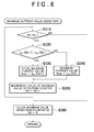
- the maximum value detection counter threshold value K N1 is the number of times the current A/D value is acquired during the period T1. For example, as shown in FIG. 3 , in a case where the current A/D value is acquired twice during the period T1, K N1 is 2.
- the process proceeds to S320.
- the microcomputer 32 compares the current A/D values acquired by the upper current acquisition process. For example, when the current A/D value stored in a predetermined region I AD [N2+1] of the RAM 32b is larger than the current A/D value stored in a predetermined region I AD [N2] (S320: YES), the process executed by the microcomputer 32 proceeds to S330. On the other hand, when the current A/D value stored in the predetermined region I AD [N2+1] is equal to or smaller than the current A/D value stored in the predetermined region I AD [N2] (S320: NO), the process proceeds to S340.
- the microcomputer 32 stores the current A/D value, which is stored in the predetermined region I AD [N2+1], in the predetermined region Imax of the RAM 32b. Then, the process proceeds to S350.
- the microcomputer 32 stores the current A/D value, which is stored in the predetermined region I AD [N2], in the predetermined region Imax of the RAM 32b. Then, the process proceeds to S350.
- the microcomputer 32 increments the value of the maximum value detection counter N2 (N2 ⁇ N2 + 1). Then, the process proceeds to S310. In S310, when the value of the maximum value detection counter N2 exceeds the maximum value detection counter threshold value K N1 (S310: NO), the process proceeds to S360.
- the microcomputer 32 clears the value of the maximum value detection counter N2 (N2 ⁇ 0), and the program processing is ended.
- the microcomputer 32 determines that there is an overcurrent abnormality in the driving force distribution control device 31 due to a short circuit between both terminals of the electromagnetic solenoid 22.
- the microcomputer 32 changes the driving mode of the four-wheel drive vehicle 11 from the four-wheel drive mode (4WD) to the two-wheel drive mode (2WD) when an overcurrent abnormality occurs in the driving force distribution control device 31, that is, when both terminals of the electromagnetic solenoid 22 are short-circuited. Accordingly, even if an overcurrent abnormality occurs in the driving force distribution control device 31, the four-wheel drive vehicle 11 can travel.
- the microcomputer 32 is provided as a device that determines whether or not there is an abnormality in the electromagnetic solenoid 22.
- the microcomputer 32 detects the maximum current value among the values of the upper current (actual current flowing through the shunt resistor 41a) acquired during the predetermined period T1, and determines that an overcurrent abnormality has occurred in the driving force distribution control device 31 when the maximum current value is equal to or larger than the abnormal current threshold value K Imax and the detection time, for which the maximum current value is equal to or larger than the abnormal current threshold value K Imax , is equal to or larger than the abnormality detection time.
- the driving force distribution control device 31 it is possible to quickly detect the overcurrent abnormality in the driving force distribution control device 31 due to a short circuit between both terminals of the electromagnetic solenoid 22, as compared to a known driving force distribution control device that determines whether or not there is an overcurrent abnormality based on the average value of the acquired current values, for example. Unless the abnormality detection time has passed (the detection time, for which the maximum current value is equal to or larger than the abnormal current threshold value K Imax , is equal to or larger than the abnormality detection time), it is not determined that there is an overcurrent abnormality. Therefore, it is also possible to suppress erroneous detection of an overcurrent abnormality in the driving force distribution control device 31.
- the microcomputer 32 performs the off control to turn off the relay 35 when it is determined that there is an overcurrent abnormality. Therefore, when it is determined that there is an overcurrent abnormality, it is possible to stop the supply of electric power to the electromagnetic solenoid 22. Accordingly, it is possible to prevent damage to an element, in particular, an element present between the battery 38 and the electromagnetic solenoid 22 due to the overcurrent abnormality in the driving force distribution control device 31.
- the microcomputer 32 When it is determined that there is an overcurrent abnormality in the driving force distribution control device 31, the microcomputer 32 notifies the driver of occurrence of the overcurrent abnormality in the driving force distribution control device 31 by turning on the warning light 50. Thus, it is possible to draw attention of the driver to the overcurrent abnormality in the driving force distribution control device 31.
- the abnormality detection time counter threshold value K Tmax in an example may be set according to the abnormal current threshold value K Imax .
- a map M is stored in the ROM 32a. As shown in FIG. 7 , the map M shows the correlation between the abnormal current threshold value K Imax and the abnormality detection time counter threshold value K Tmax .
- the microcomputer 32 sets the abnormality detection time counter threshold value K Tmax according to the abnormal current threshold value K Imax . That is, when the abnormal current threshold value K Imax is large, the abnormality detection time counter threshold value K Tmax is set to be short.
- This process is executed, for example, every time the state of the ignition switch 40 is changed from the OFF state to the ON state.
- the overcurrent abnormality in the driving force distribution control device 31 can be more quickly detected by setting the abnormality detection time counter threshold value K Tmax according to the detected maximum current value.
- the maximum value detection counter threshold value K N1 acquired during the period T1 may be appropriately changed.
- the maximum value detection counter threshold value K N1 may be set to 1.
- the maximum value detection counter threshold value K N1 is 1, it is possible to set the value of the current, which actually flows through the shunt resistor 41a, as the maximum current value and determine whether or not there is an overcurrent abnormality in the driving force distribution control device 31 based on the abnormality determination program in this example.
- the abnormality detection time counter threshold value K Tmax may be appropriately changed.
- the abnormality detection time counter threshold value K Tmax may be set to 1 or more.
- the microcomputer 32 determines that an overcurrent abnormality has occurred in the driving force distribution control device 31 when an abnormal current is detected once. Also in this case, it is possible to determine whether or not there is an overcurrent abnormality in the driving force distribution control device 31.
- an electrical load control device and an abnormality determination device are embodied as the driving force distribution control device 31 in the present embodiment, the electrical load control device and the abnormality determination device are not limited to this device.
- the electrical load control device and the abnormality determination device are embodied as a motor control device that controls an electric motor as an electrical load. In this case, it is possible to determine whether or not there is an abnormality in the motor control device due to an overcurrent that is caused by a short circuit between both terminals of the coil of the motor.
- warning light 50 is provided as a notification unit in the present embodiment, a speaker that generates a warning sound or a warning sound generator that generates a warning message through a synthetic sound circuit or the like may be provided as a notification unit.
- a microcomputer (32) of a driving force distribution control device (31) detects a maximum current value among values of an upper current (actual current flowing through a shunt resistor (41a) on a power supply side) acquired during a predetermined period, and determines that an overcurrent abnormality has occurred in the driving force distribution control device (31) when the maximum current value is equal to or larger than an abnormal current threshold value and a time, for which the maximum current value is equal to or larger than the abnormal current threshold value, is equal to or larger than an abnormality detection time. Then, the microcomputer (32) performs off control to turn off a relay (35), and notifies a driver of occurrence of the overcurrent abnormality using a notification unit (50).
Landscapes
- Engineering & Computer Science (AREA)
- General Engineering & Computer Science (AREA)
- Physics & Mathematics (AREA)
- Fluid Mechanics (AREA)
- Mechanical Engineering (AREA)
- Automation & Control Theory (AREA)
- Human Computer Interaction (AREA)
- Transportation (AREA)
- Electromagnetism (AREA)
- Arrangement And Driving Of Transmission Devices (AREA)
- Testing Of Short-Circuits, Discontinuities, Leakage, Or Incorrect Line Connections (AREA)
- Emergency Protection Circuit Devices (AREA)
Abstract
Description
- The invention relates to an electrical load control device including an overcurrent abnormality determination device, an overcurrent abnormality determination method for an electrical load control device, and an overcurrent abnormality determination program.
- Generally, a driving force distribution device of a four-wheel drive vehicle directly transmits a driving force from a transmission to either front wheels or rear wheels and also distributes and transmits the driving force to the other of the front wheels and the rear wheels through a variable torque clutch mechanism. By adjusting the transmission torque using this mechanism, the distribution of the driving force to the front and rear wheels is adjusted. As the variable torque clutch mechanism, an electromagnetic variable torque clutch mechanism is known. The electromagnetic variable torque clutch mechanism is controlled by a driving force distribution control device (ECU). That is, the frictional engagement force between clutch discs is variably controlled to control the fastening force by controlling the value of a current supplied to an electromagnetic solenoid using the ECU. Thus, the transmission torque is controlled. More specifically, the ECU generates a current command value (the amount of the current to be supplied to the electromagnetic solenoid), and calculates a duty ratio to eliminate the deviation between the current command value and the actual current (detection current) flowing through the electromagnetic solenoid by using proportional and integral control (PI control) and Pulse Width Modulation (PWM) control. The ECU controls the electromagnetic solenoid by outputting a control signal corresponding to the duty ratio to the driving circuit.
- When a short-circuit failure occurs between both ends of the electromagnetic solenoid, there is a possibility that a hunting phenomenon may occur. The hunting phenomenon refers to a phenomenon in which excessive current (actual current) flows when a field effect transistor (FET) of the driving circuit is turned on in a state where a short-circuit failure occurs between both ends of the electromagnetic solenoid. Since the ECU performs the PI control, the ECU performs control so that the current is reduced to zero or a current value near zero by reducing the duty ratio when an excessive actual current is detected. When the current becomes zero, the ECU performs control so that a current flows again. As a result, an excessive current flows.
- A driving force distribution control device that determines whether or not there is a short circuit between both ends of an electromagnetic solenoid based on the detection of a hunting phenomenon is known (for example, refer to Japanese Patent Application Publication No.
2004-142726 JP 2004-142726 A - In the driving force distribution control device (ECU) described in Japanese Patent Application Publication No.
2004-142726 JP 2004-142726 A - An object of the invention is to more quickly detect an overcurrent abnormality in an electrical load control device due to a short circuit between both terminals of an electrical load.
- According to an aspect of the invention, there is provided an abnormality determination method for determining whether or not there is an abnormality in an electrical load control device that calculates a duty ratio to eliminate a difference between a current command value indicating a current to be supplied to an electrical load and a current value that is an actually detected value of a current flowing through the electrical load, and performs pulse width modulation control to control driving of the electrical load based on the duty ratio. In the abnormality determination method, a determination is made that there is an overcurrent abnormality, when a maximum current value, which is a largest current value among the current values sampled at timings based on the duty ratio, is equal to or larger than an abnormal current threshold value and a detection time, for which an abnormal current is detected, is equal to or larger than an abnormality detection time threshold value.
- With this configuration, it is possible to more quickly detect an overcurrent abnormality in the electrical load control device due to a short circuit between both terminals of the electrical load.
- According to an aspect of the invention, there is provided an electrical load control device including an abnormality determination device. The electrical load control device calculates a duty ratio to eliminate a difference between a current command value indicating a current to be supplied to an electrical load and a current value that is an actually detected value of a current flowing through the electrical load, and the electrical load control device performs pulse width modulation control to control driving of the electrical load based on the duty ratio. The abnormality determination device includes a maximum current value detection unit that detects a maximum current value that is a largest current value among the current values; an abnormal current determination unit that determines whether or not there is an abnormal current based on a result of comparison between the detected maximum current value and an abnormal current threshold value; an abnormality detection time determination unit that determines whether or not a detection time, for which the abnormal current is detected, is equal to or larger than an abnormality detection time threshold value based on a result of comparison between the detection time and the abnormality detection time threshold value; and an abnormality determination unit that determines that there is an overcurrent abnormality when the maximum current value is equal to or larger than the abnormal current threshold value and the detection time is equal to or larger than the abnormality detection time threshold value.
- With this configuration, the abnormality determination unit determines that there is the overcurrent abnormality when the maximum current value is equal to or larger than the abnormal current threshold value and the detection time is equal to or larger than the abnormality detection time threshold value. Thus, it is possible to determine whether or not there is the overcurrent abnormality in the electrical load control device due to a short circuit in the electrical load, based on the maximum current value that is the maximum value of the current flowing through the electrical load.
- In the electrical load control device according to the above-mentioned aspect, the electrical load may be connected to a power supply through a relay in the abnormality determination device, and the abnormality determination unit may perform off control to turn off the relay when the abnormality determination unit determines that there is the overcurrent abnormality in the electrical load control device.
- With this configuration, the abnormality determination unit performs off control to turn off the relay when the abnormality determination unit determines that there is the overcurrent abnormality in the electrical load control device. By performing the off control to turn off the relay when it is determined that there is the abnormality in the electrical load, it is possible to prevent damage to an element provided between the power supply for the electrical load control device and the electrical load.
- In the electrical load control device according to the above-mentioned aspect, the abnormality determination device may include a notification unit that provides a notification that there is the overcurrent abnormality when the abnormality determination unit determines that there is the overcurrent abnormality. With this configuration, a driver is notified that the abnormality is detected through the notification unit. Thus, it is possible to draw the driver's attention to the overcurrent abnormality due to a short circuit between both terminals of the electrical load.
- In the electrical load control device according to the above-mentioned aspect, a map showing a correlation between the maximum current value and the abnormality detection time threshold value may be stored in the electrical load control device, and the abnormality determination unit may set the abnormality detection time threshold value based on the detected maximum current value and the map.
- With this configuration, the abnormality detection time threshold value is set based on the maximum current value that is the maximum value of the current flowing through the electrical load. When the maximum current value is large, the abnormality detection time threshold value is set to be small, and when the maximum current value is small, the abnormality detection time threshold value is set to be large. Thus, when a short circuit occurs in the electrical load, it is possible to more quickly detect the overcurrent abnormality in the electrical load control device. Since the abnormality detection time threshold value is set to be large when the maximum current value is small, it is possible to suppress an erroneous detection of the overcurrent abnormality in the electrical load control device.
- The electrical load control device according to the above-mentioned aspect may be configured to control, as the electrical load, a driving force distribution device that adjusts a ratio between driving forces transmitted from a driving source of a vehicle to a plurality of wheels through a driving force transmission system.
- With this configuration, it is possible to quickly detect the overcurrent due to a short circuit in the electrical load. In addition, it is possible to prevent damage to an element provided in a path, particularly, an element provided between the power supply and the electrical load in the driving force distribution control device.
- According to an aspect of the invention, there is provided an abnormality determination program for determining whether or not there is an abnormality in an electrical load control device that calculates a duty ratio to eliminate a difference between a current command value indicating a current to be supplied to an electrical load and a current value that is an actually detected value of a current flowing through the electrical load, and performs pulse width modulation control to control driving of the electrical load based on the duty ratio. The abnormality determination program includes a maximum current value detection step of detecting a maximum current value that is a largest current value among the current values sampled at timings based on the duty ratio; an abnormal current determination step of determining whether or not there is an abnormal current based on a result of comparison between the detected maximum current value and an abnormal current threshold value; and an abnormality detection time determination step of determining whether or not a detection time, for which the abnormal current is detected, is equal to or larger than an abnormality detection time threshold value based on a result of comparison between the detection time and the abnormality detection time threshold value. A determination is made as to whether there is an overcurrent abnormality in the electrical load control device based on a determination result in each of the abnormal current determination step and the abnormality detection time determination step.
- With this configuration, a determination is made as to whether there is the overcurrent abnormality in the electrical load control device based on a detection result in the maximum current value detection step and a determination result in each of the abnormal current determination step and the abnormality detection time determination step. Thus, it is possible to determine whether there is the overcurrent abnormality in the electrical load control device due to a short circuit between both terminals of the electrical load.
- The foregoing and further features and advantages of the invention will become apparent from the following description of example embodiments with reference to the accompanying drawings, wherein like numerals are used to represent like elements and wherein:
-
FIG. 1 is a schematic configuration diagram of a four-wheel drive vehicle according to an embodiment; -
FIG. 2 is a circuit diagram showing an electrical configuration of a driving force distribution control device according to the embodiment; -
FIG. 3 is a diagram including a graph A that is an explanatory diagram showing a correlation between a duty ratio and a time, a graph B that is an explanatory diagram showing a change in a current flowing between a battery and an electromagnetic solenoid with respect to a time axis of the graph A, and a graph C that is a timing chart showing A/D sampling with respect to the time axis of the graph A; -
FIG. 4 is a flowchart showing a flow of an upper current acquisition process in the embodiment; -
FIG. 5 is a flowchart showing a flow of an abnormality determination process in the embodiment; -
FIG. 6 is a flowchart showing a flow of a maximum current value detection process in the embodiment; and -
FIG. 7 is a map showing a correlation between an abnormal current threshold value and an abnormality detection time in another embodiment. - Hereinafter, an embodiment of a driving force distribution control device will be described. As shown in
FIG. 1 , a four-wheel drive vehicle 11 includes anengine 12 that constitutes a driving source and atransaxle 13. Thetransaxle 13 includes a transmission, a transfer, and the like. A pair offront axles propeller shaft 15 are connected to thetransaxle 13.Front wheels front axles force transmission device 17 as a driving force distribution device is connected to thepropeller shaft 15, and a rear differential 18 is connected to the drivingforce transmission device 17 through a drive pinion shaft (not shown).Rear wheels rear axles - The driving force of the
engine 12 is transmitted to thefront wheels transaxle 13 and thefront axles propeller shaft 15 and the drive pinion shaft are connected to each other through the drivingforce transmission device 17 so that the torque can be transmitted, the driving force of theengine 12 is transmitted to therear wheels propeller shaft 15, the drive pinion shaft, the rear differential 18, and therear axles - A driving force transmission system is constituted by the
transaxle 13, thefront axles propeller shaft 15, the drive pinion shaft, the drivingforce transmission device 17, the rear differential 18, and therear axles - The driving
force transmission device 17 includes a wet multi-disc type electromagneticclutch mechanism 21, and the electromagneticclutch mechanism 21 includes a plurality of clutch discs (not shown) that are frictionally engaged with each other or are spaced apart from each other. When a predetermined current is supplied to an electromagnetic solenoid 22 (refer toFIG. 2 ) as an electrical load provided in the electromagneticclutch mechanism 21, the clutch discs are frictionally engaged with each other, and the torque (driving force) is transmitted between thefront wheels rear wheels clutch mechanism 21 is stopped, the clutch discs are spaced apart from each other, and the transmission of torque between thefront wheels rear wheels - The frictional engagement force between the clutch discs increases or decreases according to the amount (intensity) of the current supplied to the
electromagnetic solenoid 22. By controlling the amount of the current supplied to theelectromagnetic solenoid 22, transmission torque between thefront wheels rear wheels front wheels rear wheels front wheels rear wheels - The supply of the current to the
electromagnetic solenoid 22, the stopping of the supply of the current to theelectromagnetic solenoid 22, and the adjustment of the amount of supplied current are controlled by a driving force distribution control device 31 (4WD-ECU) that is an electronic control device for driving force distribution. The driving forcedistribution control device 31 selects either a four-wheel drive state or a two-wheel drive state, and controls the driving force distribution ratio (torque distribution ratio) between thefront wheels rear wheels clutch mechanism 21. - The electrical configuration of the driving force
distribution control device 31 of the four-wheel drive vehicle 11 will be described with reference toFIG. 2 . As shown inFIG. 2 , the driving forcedistribution control device 31 of the four-wheel drive vehicle 11 is configured to include, as a main component, amicrocomputer 32 including a central processing unit (CPU), a read only memory (ROM) 32a and a random access memory (RAM) 32b that constitute a storage unit, an input interface, and the like. Themicrocomputer 32 corresponds to an abnormality determination unit. - Various programs executed by the
microcomputer 32, various data, and various characteristic maps are stored in theROM 32a. The various characteristic maps are obtained in advance based on experimental data obtained by using a vehicle model, known theoretical calculated values, and the like. TheRAM 32b is a work area in which various control programs written in theROM 32a are loaded so that the CPU of the driving forcedistribution control device 31 executes various kinds of arithmetic processing (for example, arithmetic processing for controlling the supply of the current to the electromagnetic solenoid 22). -
Wheel speed sensors 33, athrottle opening sensor 34, arelay 35,current detection circuits warning light 50 are connected to themicrocomputer 32 through an input/output interface (not shown). - The
wheel speed sensors 33 are provided for the right and leftfront wheels rear wheels wheel speed sensors 33 detect the wheel speeds of thefront wheels rear wheels microcomputer 32. The wheel speed is the rotation speed that is the number of revolutions of the wheel per unit time. - The
throttle opening sensor 34 is connected to a throttle valve (not shown), and detects the opening degree of the throttle valve (throttle opening), that is, the amount of depressing operation of an accelerator pedal (not shown) depressed by the driver. The throttle opening sensor transmits the detection result (depressing operation amount signal) to themicrocomputer 32. - The
warning light 50 is turned on according to the control of themicrocomputer 32. Thewarning light 50 corresponds to a notification unit. The four-wheel drive vehicle 11 includes abattery 38. A series circuit of afuse 39, anignition switch 40, therelay 35, ashunt resistor 41a, a field effect transistor (hereinafter, referred to as a FET 42), theelectromagnetic solenoid 22, and ashunt resistor 41b is connected to both ends of thebattery 38. - Both ends of the
shunt resistor 41a are connected to the input side of thecurrent detection circuit 36a, and both ends of theshunt resistor 41b are connected to the input side of thecurrent detection circuit 36b. Thecurrent detection circuit 36a detects a current flowing through theshunt resistor 41a based on a voltage between both ends of theshunt resistor 41a and thecurrent detection circuit 36b detects a current flowing through theshunt resistor 41b based on a voltage between both ends of theshunt resistor 41b, and thecurrent detection circuits microcomputer 32. Themicrocomputer 32 calculates a current flowing through theelectromagnetic solenoid 22 based on the actual current flowing through theshunt resistor 41a, which is transmitted from thecurrent detection circuit 36a. Aflywheel diode 43 is connected to both ends of theelectromagnetic solenoid 22. Theflywheel diode 43 is provided to eliminate the back electromotive force generated when theFET 42 is turned off, and theFET 42 is protected by theflywheel diode 43. A gate G of theFET 42 is connected to the output side of themicrocomputer 32. A source S of theFET 42 is connected to the positive terminal of theelectromagnetic solenoid 22, and a drain D of theFET 42 is connected to theshunt resistor 41a. - When the
ignition switch 40 is turned on (closed), electric power is supplied from thebattery 38 as a power supply to themicrocomputer 32 through a power supply circuit (not shown). Themicrocomputer 32 calculates the amount of the current to be supplied to the electromagnetic solenoid 22 (current command value) by executing various control programs, such as a driving force distribution control program, based on various kinds of information (detection signals) obtained from thewheel speed sensor 33 and thethrottle opening sensor 34. - More specifically, the
microcomputer 32 generates (sets) the current command value for theelectromagnetic solenoid 22 based on various kinds of information (detection signals) obtained from thewheel speed sensors 33 and thethrottle opening sensor 34. Themicrocomputer 32 calculates a PI control value by using PI control in order to eliminate the deviation between the current command value and the actual current flowing through theelectromagnetic solenoid 22. Themicrocomputer 32 determines a duty ratio by performing the PWM calculation according to the calculated PI control value, and performs ON/OFF control (PWM control) for theFET 42 so that a voltage controlled based on the duty ratio is applied to theelectromagnetic solenoid 22. Themicrocomputer 32 variably controls the driving force distribution between the front wheel side and the rear wheel side by controlling the voltage applied to theelectromagnetic solenoid 22. - When the
ignition switch 40 is turned off (opened), the supply of electric power to themicrocomputer 32 is stopped. When an overcurrent abnormality to be described later is detected, themicrocomputer 32 notifies the user of occurrence of the overcurrent abnormality in the driving forcedistribution control device 31 by turning on thewarning light 50. - Next, the overcurrent abnormality determination process executed by the
microcomputer 32 will be described in detail with reference toFIG. 3 and flowcharts shown inFIGS. 4 to 6 . The flowcharts are executed based on various control programs stored in advance in theROM 32a. Hereinafter, a step will be abbreviated as S. - First, a process of acquiring the upper current (precisely, the actual current flowing through the
shunt resistor 41a) executed by themicrocomputer 32 will be described. As shown inFIG. 3 where the period for which the duty is ON is a period Ton and the period for which the duty is OFF is a period Toff, themicrocomputer 32 acquires the upper current through thecurrent detection circuit 36a during the period Ton. A period Tad for A/D sampling is a period shorter than the period Ton. Accordingly, it is possible to acquire the upper current in every period Ton for which the duty is ON. - As shown in
FIG. 4 , in S110, themicrocomputer 32 performs A/D (IADin) conversion of the upper current acquired through thecurrent detection circuit 36a. Then, the process proceeds to S120. In S120, themicrocomputer 32 stores the current A/D value in a predetermined region IAD [N1] of theRAM 32b. Then, the process proceeds to S130. - In S130, the
microcomputer 32 increments the value of an A/D counter N1 (N1 ← N1 + 1). Then, the process ends. The increment refers to increasing the value of the A/D counter N1 by 1, for example. - The
microcomputer 32 acquires the upper current every predetermined period Ton, and stores the acquired upper current in the predetermined region IAD[N1] of theRAM 32b. Next, the overcurrent abnormality determination process executed by themicrocomputer 32 will be described with reference to the flowchart shown inFIG. 5 . - As shown in
FIG. 5 , in S210, themicrocomputer 32 clears the cumulative value of the A/D counter N1 (N1 ← 0). Then, the process proceeds to S220. In S220, themicrocomputer 32 detects a maximum current value that is the largest value among the values of the upper current acquired during the period T1. Then, the process proceeds to S230. - In S230, the
microcomputer 32 determines whether or not there is an overcurrent abnormality by comparing the maximum current value detected in S220 with an abnormal current threshold value KImax. More specifically, when themicrocomputer 32 determines that the detected maximum current value is equal to or larger than the abnormal current threshold value KImax (S230: YES), the process proceeds to S240. On the other hand, when themicrocomputer 32 determines that the maximum current value is smaller than the abnormal current threshold value KImax (S230: NO), the process proceeds to S290. In S290, themicrocomputer 32 clears the value of an abnormality detection time counter TImax (TImax ← 0). Then, the process proceeds to S295. S230 corresponds to an abnormal current determination step. The abnormal current threshold value KImax is set to a value lower than a detection current detected when the duty ratio is set to, for example, X% in a state where both terminals of theelectromagnetic solenoid 22 are short-circuited. Therefore, it is possible to determine whether or not the detection current is an abnormal current by comparing the detection current with the abnormal current threshold value KImax. The abnormal current threshold value KImax is determined in advance by a test and the like, and is stored in theROM 32a. - In S240, the
microcomputer 32 increments the value of the abnormality detection time counter TImax (TImax ← TImax + 1). Then, the process executed by themicrocomputer 32 proceeds to S250. - In S250, the
microcomputer 32 determines whether or not the detection time (the number of times an abnormal current is detected), for which an abnormal current is detected, is equal to or larger than an abnormality detection time. More specifically, when the value of the abnormality detection time counter TImax is equal to or larger than the abnormality detection time counter threshold value KTmax (S250:YES), the process executed by themicrocomputer 32 proceeds to S260. On the other hand, when the value of the abnormality detection time counter TImax is smaller than the abnormality detection time counter threshold value KTmax that is a reference value used for determining whether or not there is an abnormality (S250: NO), the process executed by themicrocomputer 32 proceeds to S295. - The abnormality detection time counter threshold value KTmax is the number of times an abnormal current is detected. Therefore, the detection time, for which an abnormality is detected, is determined by multiplying the value of the abnormality detection time counter TImax by the period of the overcurrent abnormality determination process. Similarly, the abnormality detection time, which is a reference used for determining whether or not the detection time is abnormal, is determined by multiplying the abnormality detection time counter threshold value KTmax by the period of the overcurrent abnormality determination process. Therefore, it is possible to determine whether or not the abnormality detection time has passed (the detection time is equal to or larger than the abnormality detection time), by comparing the value of the abnormality detection time counter TImax with the abnormality detection time counter threshold value KTmax. The abnormality detection time counter threshold value KTmax is determined by a test and the like, and is stored in the
ROM 32a. S250 corresponds to an abnormality detection time determination step. The abnormality detection time counter threshold value KTmax corresponds to an abnormality detection time threshold value. - In S260, the
microcomputer 32 performs off control to turn off therelay 35. That is, when it is determined that the detected maximum current value is equal to or larger than the abnormal current threshold value KImax and the detection time is equal to or larger than the abnormality detection time, the supply of electric power to theelectromagnetic solenoid 22 is stopped by performing the off control to turn off therelay 35. - In S270, when the
microcomputer 32 determines that there is an overcurrent abnormality, themicrocomputer 32 notifies the driver of occurrence of the overcurrent abnormality in the driving forcedistribution control device 31 by turning on thewarning light 50. In S280, themicrocomputer 32 holds the value of the abnormality detection time counter TImax (TImax ← KTmax). Then, the process proceeds to S295. - In S295, the
microcomputer 32 clears the maximum current value stored in a predetermined region Imax (Imax ← 0), and the processing of the flowchart is ended. Themicrocomputer 32 functions as an abnormality determination device. In this case, themicrocomputer 32 functions as a maximum current value detection unit that executes the process of S220, an abnormal current determination unit that executes the process of S230, and an abnormality detection time determination unit that executes the process of S250. - Next, a process of detecting the maximum value among the current A/D values acquired by the upper current acquisition process executed by the
microcomputer 32 will be described with reference to the flowchart shown inFIG. 6 . As shown inFIG. 6 , in S310, themicrocomputer 32 determines whether or not the value of a maximum value detection counter N2 is equal to or smaller than a maximum value detection counter threshold value KN1. The maximum value detection counter threshold value KN1 is the number of times the current A/D value is acquired during the period T1. For example, as shown inFIG. 3 , in a case where the current A/D value is acquired twice during the period T1, KN1 is 2. - When the value of the maximum value detection counter N2 is equal to or smaller than the maximum current value detection counter threshold value KN1 (S310: YES), the process proceeds to S320. In S320, the
microcomputer 32 compares the current A/D values acquired by the upper current acquisition process. For example, when the current A/D value stored in a predetermined region IAD [N2+1] of theRAM 32b is larger than the current A/D value stored in a predetermined region IAD [N2] (S320: YES), the process executed by themicrocomputer 32 proceeds to S330. On the other hand, when the current A/D value stored in the predetermined region IAD [N2+1] is equal to or smaller than the current A/D value stored in the predetermined region IAD [N2] (S320: NO), the process proceeds to S340. - In S330, the
microcomputer 32 stores the current A/D value, which is stored in the predetermined region IAD [N2+1], in the predetermined region Imax of theRAM 32b. Then, the process proceeds to S350. In S340, themicrocomputer 32 stores the current A/D value, which is stored in the predetermined region IAD [N2], in the predetermined region Imax of theRAM 32b. Then, the process proceeds to S350. - In S350, the
microcomputer 32 increments the value of the maximum value detection counter N2 (N2 ← N2 + 1). Then, the process proceeds to S310. In S310, when the value of the maximum value detection counter N2 exceeds the maximum value detection counter threshold value KN1 (S310: NO), the process proceeds to S360. - In S360, the
microcomputer 32 clears the value of the maximum value detection counter N2 (N2 ← 0), and the program processing is ended. Thus, when the upper current acquired during the predetermined period T1 is equal to or larger than the abnormal current threshold value (S230) and the abnormality detection time has passed (the detection time is equal to or larger than the abnormality detection time) (S250), themicrocomputer 32 determines that there is an overcurrent abnormality in the driving forcedistribution control device 31 due to a short circuit between both terminals of theelectromagnetic solenoid 22. Therefore, it is possible to quickly detect the overcurrent abnormality in the driving forcedistribution control device 31 due to a short circuit between both terminals of theelectromagnetic solenoid 22, as compared to a known driving force distribution control device that determines whether or not there is an overcurrent abnormality based on the average value of the acquired current values, for example. Further, it is possible to prevent damage to an element provided between thebattery 38 and theelectromagnetic solenoid 22. - The
microcomputer 32 changes the driving mode of the four-wheel drive vehicle 11 from the four-wheel drive mode (4WD) to the two-wheel drive mode (2WD) when an overcurrent abnormality occurs in the driving forcedistribution control device 31, that is, when both terminals of theelectromagnetic solenoid 22 are short-circuited. Accordingly, even if an overcurrent abnormality occurs in the driving forcedistribution control device 31, the four-wheel drive vehicle 11 can travel. - According to the embodiment described above, the following effects can be obtained. In the driving force
distribution control device 31, themicrocomputer 32 is provided as a device that determines whether or not there is an abnormality in theelectromagnetic solenoid 22. Themicrocomputer 32 detects the maximum current value among the values of the upper current (actual current flowing through theshunt resistor 41a) acquired during the predetermined period T1, and determines that an overcurrent abnormality has occurred in the driving forcedistribution control device 31 when the maximum current value is equal to or larger than the abnormal current threshold value KImax and the detection time, for which the maximum current value is equal to or larger than the abnormal current threshold value KImax, is equal to or larger than the abnormality detection time. Thus, it is possible to quickly detect the overcurrent abnormality in the driving forcedistribution control device 31 due to a short circuit between both terminals of theelectromagnetic solenoid 22, as compared to a known driving force distribution control device that determines whether or not there is an overcurrent abnormality based on the average value of the acquired current values, for example. Unless the abnormality detection time has passed (the detection time, for which the maximum current value is equal to or larger than the abnormal current threshold value KImax, is equal to or larger than the abnormality detection time), it is not determined that there is an overcurrent abnormality. Therefore, it is also possible to suppress erroneous detection of an overcurrent abnormality in the driving forcedistribution control device 31. - The
microcomputer 32 performs the off control to turn off therelay 35 when it is determined that there is an overcurrent abnormality. Therefore, when it is determined that there is an overcurrent abnormality, it is possible to stop the supply of electric power to theelectromagnetic solenoid 22. Accordingly, it is possible to prevent damage to an element, in particular, an element present between thebattery 38 and theelectromagnetic solenoid 22 due to the overcurrent abnormality in the driving forcedistribution control device 31. - When it is determined that there is an overcurrent abnormality in the driving force
distribution control device 31, themicrocomputer 32 notifies the driver of occurrence of the overcurrent abnormality in the driving forcedistribution control device 31 by turning on thewarning light 50. Thus, it is possible to draw attention of the driver to the overcurrent abnormality in the driving forcedistribution control device 31. - The invention can be implemented in the following modified examples obtained by appropriately modifying the embodiment described above. The abnormality detection time counter threshold value KTmax in an example may be set according to the abnormal current threshold value KImax. In this case, a map M is stored in the
ROM 32a. As shown inFIG. 7 , the map M shows the correlation between the abnormal current threshold value KImax and the abnormality detection time counter threshold value KTmax. On the basis of the map, themicrocomputer 32 sets the abnormality detection time counter threshold value KTmax according to the abnormal current threshold value KImax. That is, when the abnormal current threshold value KImax is large, the abnormality detection time counter threshold value KTmax is set to be short. This process is executed, for example, every time the state of theignition switch 40 is changed from the OFF state to the ON state. The overcurrent abnormality in the driving forcedistribution control device 31 can be more quickly detected by setting the abnormality detection time counter threshold value KTmax according to the detected maximum current value. - The maximum value detection counter threshold value KN1 acquired during the period T1 may be appropriately changed. For example, the maximum value detection counter threshold value KN1 may be set to 1. When the maximum value detection counter threshold value KN1 is 1, it is possible to set the value of the current, which actually flows through the
shunt resistor 41a, as the maximum current value and determine whether or not there is an overcurrent abnormality in the driving forcedistribution control device 31 based on the abnormality determination program in this example. - The abnormality detection time counter threshold value KTmax may be appropriately changed. For example, the abnormality detection time counter threshold value KTmax may be set to 1 or more. For example, if the abnormality detection time counter threshold value KTmax is 1, the
microcomputer 32 determines that an overcurrent abnormality has occurred in the driving forcedistribution control device 31 when an abnormal current is detected once. Also in this case, it is possible to determine whether or not there is an overcurrent abnormality in the driving forcedistribution control device 31. - Although an electrical load control device and an abnormality determination device are embodied as the driving force
distribution control device 31 in the present embodiment, the electrical load control device and the abnormality determination device are not limited to this device. For example, the electrical load control device and the abnormality determination device are embodied as a motor control device that controls an electric motor as an electrical load. In this case, it is possible to determine whether or not there is an abnormality in the motor control device due to an overcurrent that is caused by a short circuit between both terminals of the coil of the motor. - Although the
warning light 50 is provided as a notification unit in the present embodiment, a speaker that generates a warning sound or a warning sound generator that generates a warning message through a synthetic sound circuit or the like may be provided as a notification unit. - A microcomputer (32) of a driving force distribution control device (31) detects a maximum current value among values of an upper current (actual current flowing through a shunt resistor (41a) on a power supply side) acquired during a predetermined period, and determines that an overcurrent abnormality has occurred in the driving force distribution control device (31) when the maximum current value is equal to or larger than an abnormal current threshold value and a time, for which the maximum current value is equal to or larger than the abnormal current threshold value, is equal to or larger than an abnormality detection time. Then, the microcomputer (32) performs off control to turn off a relay (35), and notifies a driver of occurrence of the overcurrent abnormality using a notification unit (50).
Claims (7)
- An abnormality determination method for determining whether or not there is an abnormality in an electrical load control device that calculates a duty ratio to eliminate a difference between a current command value indicating a current to be supplied to an electrical load and a current value that is an actually detected value of a current flowing through the electrical load, and performs pulse width modulation control to control driving of the electrical load based on the duty ratio, wherein
a determination is made that there is an overcurrent abnormality, when a maximum current value, which is a largest current value among the current values sampled at timings based on the duty ratio, is equal to or larger than an abnormal current threshold value and a detection time, for which an abnormal current is detected, is equal to or larger than an abnormality detection time threshold value. - An electrical load control device comprising
an abnormality determination device,
wherein the electrical load control device calculates a duty ratio to eliminate a difference between a current command value indicating a current to be supplied to an electrical load and a current value that is an actually detected value of a current flowing through the electrical load, and the electrical load control device performs pulse width modulation control to control driving of the electrical load based on the duty ratio, and
wherein the abnormality determination device includes:a maximum current value detection unit that detects a maximum current value that is a largest current value among the current values;an abnormal current determination unit that determines whether or not there is an abnormal current based on a result of comparison between the detected maximum current value and an abnormal current threshold value;an abnormality detection time determination unit that determines whether or not a detection time, for which the abnormal current is detected, is equal to or larger than an abnormality detection time threshold value based on a result of comparison between the detection time and the abnormality detection time threshold value; andan abnormality determination unit that determines that there is an overcurrent abnormality when the maximum current value is equal to or larger than the abnormal current threshold value and the detection time is equal to or larger than the abnormality detection time threshold value. - The electrical load control device according to claim 2, wherein the electrical load is connected to a power supply through a relay in the abnormality determination device, and the abnormality determination unit performs off control to turn off the relay when the abnormality determination unit determines that there is the overcurrent abnormality in the electrical load control device.
- The electrical load control device according to claim 2 or 3, wherein the abnormality determination device includes a notification unit that provides a notification that there is the overcurrent abnormality when the abnormality determination unit determines that there is the overcurrent abnormality.
- The electrical load control device according to any one of claims 2 to 4, wherein a map showing a correlation between the maximum current value and the abnormality detection time threshold value is stored in the electrical load control device, and
the abnormality determination unit sets the abnormality detection time threshold value based on the detected maximum current value and the map. - The electrical load control device according to any one of claims 2 to 5,
wherein the electrical load is a driving force distribution device that adjusts a ratio between driving forces transmitted from a driving source of a vehicle to a plurality of wheels through a driving force transmission system. - An abnormality determination program for determining whether or not there is an abnormality in an electrical load control device that calculates a duty ratio to eliminate a difference between a current command value indicating a current to be supplied to an electrical load and a current value that is an actually detected value of a current flowing through the electrical load, and performs pulse width modulation control to control driving of the electrical load based on the duty ratio, the abnormality determination program comprising:a maximum current value detection step of detecting a maximum current value that is a largest current value among the current values sampled at timings based on the duty ratio;an abnormal current determination step of determining whether or not there is an abnormal current based on a result of comparison between the detected maximum current value and an abnormal current threshold value; andan abnormality detection time determination step of determining whether or not a detection time, for which the abnormal current is detected, is equal to or larger than an abnormality detection time threshold value based on a result of comparison between the detection time and the abnormality detection time threshold value,wherein a determination is made as to whether there is an overcurrent abnormality in the electrical load control device based on a determination result in each of the abnormal current determination step and the abnormality detection time determination step.
Applications Claiming Priority (1)
| Application Number | Priority Date | Filing Date | Title |
|---|---|---|---|
| JP2013066611A JP6201366B2 (en) | 2013-03-27 | 2013-03-27 | Overload abnormality determination device, driving force distribution control device, overcurrent abnormality determination method, and overcurrent abnormality determination program for electric load control device |
Publications (2)
| Publication Number | Publication Date |
|---|---|
| EP2789517A2 true EP2789517A2 (en) | 2014-10-15 |
| EP2789517A3 EP2789517A3 (en) | 2014-11-26 |
Family
ID=50732762
Family Applications (1)
| Application Number | Title | Priority Date | Filing Date |
|---|---|---|---|
| EP14161414.9A Withdrawn EP2789517A3 (en) | 2013-03-27 | 2014-03-25 | Electrical load control device, abnormality determination method, and abnormality determination program |
Country Status (4)
| Country | Link |
|---|---|
| US (1) | US9664241B2 (en) |
| EP (1) | EP2789517A3 (en) |
| JP (1) | JP6201366B2 (en) |
| CN (1) | CN104070997B (en) |
Families Citing this family (16)
| Publication number | Priority date | Publication date | Assignee | Title |
|---|---|---|---|---|
| JP6257264B2 (en) * | 2013-10-29 | 2018-01-10 | 三菱電機株式会社 | Semiconductor device |
| CN105592605B (en) * | 2014-10-22 | 2018-11-20 | 上海新进半导体制造有限公司 | A kind of LED load driving circuit |
| US10886764B2 (en) | 2014-12-18 | 2021-01-05 | Koki Holdings Co., Ltd. | Power tool |
| JP6492672B2 (en) * | 2015-01-14 | 2019-04-03 | 株式会社デンソー | Load drive device |
| FR3044771B1 (en) * | 2015-12-03 | 2017-12-01 | Continental Automotive France | OPEN LOAD DETECTION METHOD |
| DE102017219633B3 (en) * | 2017-11-06 | 2019-02-28 | Conti Temic Microelectronic Gmbh | Method for checking the plausibility of measurements of an actuator current and use of the method |
| EP3590776B1 (en) * | 2018-07-04 | 2022-03-30 | NXP USA, Inc. | Resistive short circuit immunity for wheel speed sensor interface on braking system |
| US11935338B2 (en) * | 2018-07-13 | 2024-03-19 | Hitachi Astemo, Ltd. | Automotive electronic control unit |
| DE102018212845B3 (en) * | 2018-08-01 | 2019-12-05 | Volkswagen Aktiengesellschaft | A diagnostic method and apparatus for verifying operability of an electromechanical load, and a computer program product and a vehicle |
| EP3680122B1 (en) | 2019-01-09 | 2022-08-31 | NXP USA, Inc. | Companion chip short circuit immunity |
| US11664740B2 (en) | 2020-03-17 | 2023-05-30 | Hamilton Sundstrand Corporation | Threshold detection systems |
| US11796594B2 (en) * | 2020-11-05 | 2023-10-24 | Schneider Electric It Corporation | PWM capture function for event analysis |
| US12405320B2 (en) | 2020-11-05 | 2025-09-02 | Schneider Electric It Corporation | PWM capture function for event analysis |
| CN112688280B (en) * | 2020-12-29 | 2023-11-17 | 苏州博思得电气有限公司 | Power supply protection method and device for high-voltage generator and X-ray imaging system |
| JP7647599B2 (en) * | 2022-01-18 | 2025-03-18 | 株式会社デンソー | Vehicle Electronic Control Unit |
| US12398615B2 (en) * | 2023-04-21 | 2025-08-26 | Halliburton Energy Services, Inc. | Characterization and diagnosis of solenoids used in well equipment |
Citations (3)
| Publication number | Priority date | Publication date | Assignee | Title |
|---|---|---|---|---|
| EP0850817A2 (en) * | 1996-12-25 | 1998-07-01 | Mitsubishi Denki Kabushiki Kaisha | Load short-circuit failure detection method and apparatus and electric power steering device |
| JP2004142726A (en) | 2002-08-27 | 2004-05-20 | Toyoda Mach Works Ltd | Hunting detection device for electric load controller, short-circuit detection device, driving force distribution controller hunting detection method, and short-circuit method |
| WO2012102319A1 (en) * | 2011-01-26 | 2012-08-02 | 株式会社ジェイテクト | Drive force allocation control apparatus |
Family Cites Families (12)
| Publication number | Priority date | Publication date | Assignee | Title |
|---|---|---|---|---|
| JPH0826910B2 (en) * | 1989-06-30 | 1996-03-21 | 三菱電機株式会社 | Short circuit ground fault detection device for electromagnetic clutch for vehicle |
| JPH04364316A (en) * | 1991-06-11 | 1992-12-16 | Toyota Autom Loom Works Ltd | Overcurrent detecting system |
| JP3276782B2 (en) * | 1994-08-18 | 2002-04-22 | 本田技研工業株式会社 | Electric assisted bicycle |
| JP3460885B2 (en) * | 1995-03-09 | 2003-10-27 | 三菱電機株式会社 | Electric power steering control device |
| JP2003139810A (en) * | 2001-10-31 | 2003-05-14 | Toyoda Mach Works Ltd | Relay failure detecting apparatus |
| EP1747932B1 (en) * | 2002-08-27 | 2011-09-28 | JTEKT Corporation | Electrical load controlling device |
| JP4415636B2 (en) | 2002-10-10 | 2010-02-17 | 株式会社ジェイテクト | Driving force distribution control device for four-wheel drive vehicle |
| JP4471314B2 (en) | 2004-11-30 | 2010-06-02 | 株式会社オートネットワーク技術研究所 | Power supply control device |
| CN101189795B (en) * | 2005-06-03 | 2010-06-09 | 株式会社自动网络技术研究所 | Power Controllers and Semiconductor Devices |
| KR100670735B1 (en) * | 2005-07-13 | 2007-01-19 | 씨멘스브이디오한라 주식회사 | Overcurrent detector of dual motor for automobile |
| TWI369049B (en) * | 2008-04-30 | 2012-07-21 | Advanced Analog Technology Inc | Power switch circuit exhibiting over current protection and short circuit protection mechanism |
| JP5668441B2 (en) * | 2010-12-07 | 2015-02-12 | 株式会社ジェイテクト | Driving force distribution control device |
-
2013
- 2013-03-27 JP JP2013066611A patent/JP6201366B2/en not_active Expired - Fee Related
-
2014
- 2014-03-24 US US14/222,804 patent/US9664241B2/en not_active Expired - Fee Related
- 2014-03-25 EP EP14161414.9A patent/EP2789517A3/en not_active Withdrawn
- 2014-03-27 CN CN201410119018.3A patent/CN104070997B/en not_active Expired - Fee Related
Patent Citations (4)
| Publication number | Priority date | Publication date | Assignee | Title |
|---|---|---|---|---|
| EP0850817A2 (en) * | 1996-12-25 | 1998-07-01 | Mitsubishi Denki Kabushiki Kaisha | Load short-circuit failure detection method and apparatus and electric power steering device |
| JP2004142726A (en) | 2002-08-27 | 2004-05-20 | Toyoda Mach Works Ltd | Hunting detection device for electric load controller, short-circuit detection device, driving force distribution controller hunting detection method, and short-circuit method |
| WO2012102319A1 (en) * | 2011-01-26 | 2012-08-02 | 株式会社ジェイテクト | Drive force allocation control apparatus |
| EP2669108A1 (en) * | 2011-01-26 | 2013-12-04 | JTEKT Corporation | Drive force allocation control apparatus |
Also Published As
| Publication number | Publication date |
|---|---|
| JP2014190836A (en) | 2014-10-06 |
| US9664241B2 (en) | 2017-05-30 |
| US20140297144A1 (en) | 2014-10-02 |
| CN104070997A (en) | 2014-10-01 |
| JP6201366B2 (en) | 2017-09-27 |
| CN104070997B (en) | 2018-08-28 |
| EP2789517A3 (en) | 2014-11-26 |
Similar Documents
| Publication | Publication Date | Title |
|---|---|---|
| US9664241B2 (en) | Electrical load control device, abnormality determination method, and abnormality determination program | |
| US9511773B2 (en) | System and method for hybrid vehicle control during wheel slip events to limit generator speed | |
| EP1747932B1 (en) | Electrical load controlling device | |
| US20160272180A1 (en) | Abnormality information generating apparatus and vehicle control system | |
| US20130304309A1 (en) | Driving force distribution control device | |
| EP2551159A1 (en) | Control method and control apparatus for four-wheel drive vehicle | |
| JP2013092379A (en) | Relay failure detection device | |
| US8885304B2 (en) | Drive force distribution control apparatus | |
| JP4265232B2 (en) | Electric load control device hunting detection device, short circuit detection device, driving force distribution control device, hunting detection method, and short circuit detection method | |
| JP6268820B2 (en) | Driving force distribution control device | |
| JP5831037B2 (en) | Driving force distribution control device | |
| JP4415636B2 (en) | Driving force distribution control device for four-wheel drive vehicle | |
| KR101869082B1 (en) | Device and method for protecting flap adherence using actuator motor velocity and current detection | |
| US20160221602A1 (en) | Electric power steering control device | |
| KR20180027702A (en) | Vehicle control method | |
| JP5789970B2 (en) | Driving force distribution device | |
| JP2013053933A (en) | Driving force allocation control device | |
| JP7729298B2 (en) | Electric vehicles | |
| JP6404073B2 (en) | Driving force control device | |
| JP2012126241A (en) | Driving power distribution control device | |
| JP4744303B2 (en) | Air gap estimation device for electromagnetic actuator | |
| JP2015501758A (en) | Accelerator pedal system for vehicles | |
| JP2003312293A (en) | Driving force allocation controller for four-wheeled- drive vehicle | |
| JP5768363B2 (en) | Driving force distribution device | |
| JP2014083927A (en) | Driving force distribution control unit |
Legal Events
| Date | Code | Title | Description |
|---|---|---|---|
| PUAI | Public reference made under article 153(3) epc to a published international application that has entered the european phase |
Free format text: ORIGINAL CODE: 0009012 |
|
| 17P | Request for examination filed |
Effective date: 20140325 |
|
| AK | Designated contracting states |
Kind code of ref document: A2 Designated state(s): AL AT BE BG CH CY CZ DE DK EE ES FI FR GB GR HR HU IE IS IT LI LT LU LV MC MK MT NL NO PL PT RO RS SE SI SK SM TR |
|
| AX | Request for extension of the european patent |
Extension state: BA ME |
|
| PUAL | Search report despatched |
Free format text: ORIGINAL CODE: 0009013 |
|
| AK | Designated contracting states |
Kind code of ref document: A3 Designated state(s): AL AT BE BG CH CY CZ DE DK EE ES FI FR GB GR HR HU IE IS IT LI LT LU LV MC MK MT NL NO PL PT RO RS SE SI SK SM TR |
|
| AX | Request for extension of the european patent |
Extension state: BA ME |
|
| RIC1 | Information provided on ipc code assigned before grant |
Ipc: H03K 17/08 20060101ALI20141023BHEP Ipc: B60W 50/02 20120101ALI20141023BHEP Ipc: B60K 17/35 20060101ALI20141023BHEP Ipc: H02H 9/02 20060101AFI20141023BHEP Ipc: F16D 48/06 20060101ALI20141023BHEP Ipc: B60K 17/02 20060101ALI20141023BHEP |
|
| R17P | Request for examination filed (corrected) |
Effective date: 20150422 |
|
| 17Q | First examination report despatched |
Effective date: 20180504 |
|
| STAA | Information on the status of an ep patent application or granted ep patent |
Free format text: STATUS: THE APPLICATION IS DEEMED TO BE WITHDRAWN |
|
| 18D | Application deemed to be withdrawn |
Effective date: 20190326 |