EP2789469A1 - Printing device - Google Patents
Printing device Download PDFInfo
- Publication number
- EP2789469A1 EP2789469A1 EP12856332.7A EP12856332A EP2789469A1 EP 2789469 A1 EP2789469 A1 EP 2789469A1 EP 12856332 A EP12856332 A EP 12856332A EP 2789469 A1 EP2789469 A1 EP 2789469A1
- Authority
- EP
- European Patent Office
- Prior art keywords
- height adjustment
- screw
- position fixing
- hole
- platen
- Prior art date
- Legal status (The legal status is an assumption and is not a legal conclusion. Google has not performed a legal analysis and makes no representation as to the accuracy of the status listed.)
- Granted
Links
Images


Classifications
-
- B—PERFORMING OPERATIONS; TRANSPORTING
- B41—PRINTING; LINING MACHINES; TYPEWRITERS; STAMPS
- B41J—TYPEWRITERS; SELECTIVE PRINTING MECHANISMS, i.e. MECHANISMS PRINTING OTHERWISE THAN FROM A FORME; CORRECTION OF TYPOGRAPHICAL ERRORS
- B41J11/00—Devices or arrangements of selective printing mechanisms, e.g. ink-jet printers or thermal printers, for supporting or handling copy material in sheet or web form
- B41J11/20—Platen adjustments for varying the strength of impression, for a varying number of papers, for wear or for alignment, or for print gap adjustment
Definitions
- the present invention relates to a printing apparatus.
- Patent Document 1 describes an ink jet printer that is intended to adjust the parallelism of a carriage shaft relative to a platen.
- Patent Document 1 describes a technique for adjusting the height of a carriage, and the carriage is usually fixed to the Y bar with high accuracy.
- the present invention was made in the light of the circumstances as described above, and it is an object of the present invention to provide a technique for fixing the mounting table for a recording medium such as a platen with high positional accuracy and with high workability.
- a printing apparatus is characterized by including a mounting table on which a recording medium is placed, a support base for supporting the mounting table, a height adjustment mechanism for adjusting the height of the mounting table relative to the support base, and a position fixing mechanism for fixing the position of the mounting table relative to the support base at a height that is adjusted by the height adjusting mechanism, wherein a portion where the height adjustment mechanism is operated for adjustment and a portion where the position fixing mechanism is operated for fixing are on the same side as viewed from the mounting table.
- the operation of height adjustment and position fixing can be performed from the same side as viewed from the mounting table such as a platen, it is possible to perform height adjustment and position fixing easily.
- the mechanism for height adjustment and the mechanism for position fixing are in different positions and one of them is hidden in the back of another member, it may be necessary to remove the other member in order to perform height adjustment and position fixing.
- the operation for height adjustment and position fixing becomes very complicated.
- since a portion where the height adjustment mechanism is operated and a portion where the position fixing mechanism is operated are on the same side as viewed from the mounting table, it suffices that work space is provided only in one direction of the mounting table in order to adjust the respective mechanisms. Therefore, it is possible to perform height adjustment and position fixing more easily.
- the height adjustment mechanism and the position fixing mechanism are on the same straight line.
- the height adjustment mechanism is a height adjustment screw including a contact part which passes through a through hole for height adjustment screw provided in the mounting table so that a side wall of the screw is screwed to an inner wall of the through hole for height adjustment screw, and which is brought into contact with the support base, by turning the height adjustment screw, the protrusion height of the contact part protruding from the mounting table to the support base side is adjusted, so that the height of the mounting table relative to the support base is adjusted, and the position fixing mechanism is a position fixing screw which passes through a through hole for position fixing screw provided in the mounting table.
- the height adjustment mechanism and the position fixing mechanism can be realized with a simple member, a screw, it is possible to simplify the configuration of the apparatus.
- the through hole for height adjustment screw and the through hole for position fixing screw are the same through hole, an inner through hole of which center axis is a straight line parallel to the depth direction of the through hole for position fixing screw is provided in the height adjustment screw, and the position fixing screw has a flange portion having a diameter larger than the diameter of the inner through hole, and an extended portion which passes through the inner through hole and is screwed to a female screw provided in the support base.
- Fig. 1 is a side sectional view schematically showing a schematic configuration of a printing apparatus 100 according to an embodiment of the present invention.
- the printing apparatus 100 is provided with a head 10, a carriage 20, a guide mechanism 30, a platen (mounting table) 40, a bracket (support base) 50 and a conveying roller 60, and is an ink jet recording apparatus for recording (printing) an image on a medium (recording medium) 1 such as paper and cloth.
- a medium (recording medium) 1 such as paper and cloth.
- the head 10 is a recording head for discharging ink to the medium 1.
- the carriage 20 drives the head 10 and the conveying roller 60 conveys the medium 1, the head 10 and/or the medium 1 move relatively to the scanning direction and the sub scanning direction.
- the guide mechanism 30 is a member for guiding the moving direction of the carriage 20.
- the platen 40 is a mounting table which is disposed immediately below the head 10 and on which the medium 1 is placed. That is, in a state where the medium 1 is placed on the platen 40, the printing apparatus 100 records (prints) an image on the medium (recording medium) 1 by discharging ink from the head 10 while relatively moving the head 10 and/or the medium 1.
- the bracket 50 is fixed to the printing apparatus 100, and serves as a support base of the platen 40.
- the platen 40 is supported by the bracket 50, and is adjustable by an adjustment mechanism described later in a direction approaching to the head 10 and in a direction separating from the head 10.
- the adjustment mechanism includes a height adjustment mechanism for adjusting the height of the platen 40 relative to the bracket 50, and a position fixing mechanism for fixing the position of the platen 40 relative to the bracket 50 at a height that is adjusted by the height adjustment mechanism.
- the printing apparatus 100 is provided with the mechanism for adjusting the height of the platen 40 and the mechanism for fixing it relative to the bracket 50, thus, the height of the platen 40 can be adjusted and fixed.
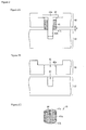
- Fig. 2 (a) is a side sectional view schematically showing a schematic configuration of the adjustment mechanism in the printing apparatus 100.
- Fig. 2 (b) is a side sectional view schematically showing a schematic configuration of the platen 40 and the bracket 50 around the adjustment mechanism.
- Fig. 2 (c) is a perspective view schematically showing a schematic configuration of the height adjustment mechanism.
- the height adjustment mechanism is constituted by a height adjustment screw 41
- the position fixing mechanism is constituted by a position fixing screw 42.
- the height adjustment screw 41 passes through a through hole (through hole for height adjustment screw and through hole for position fixing screw) 43 provided in the platen 40, so that a side wall 41a of the screw is screwed to an inner wall 43a of the through hole 43.
- the axis of the height adjustment screw 41 is a straight line parallel to the depth direction of the through hole 43, and the height adjustment screw 41 moves in the depth direction of the through hole 43 relative to the platen 40 when the height adjustment screw 41 is turned about the axis.
- an engaging groove 41c with which a screwdriver or the like is engaged is formed in the upper surface (the end opposite to the bracket 50) of the height adjustment screw 41, and when the height adjustment screw 41 is turned using a screwdriver or the like, the height adjustment screw 41 moves in the depth direction of the through hole 43. Then, the height adjustment screw 41 is protruded from the surface of the bracket 50 side of the platen 40, and a lower surface (contact part, the end of the bracket 50 side) 41b of the height adjustment screw 41 is brought into contact with the bracket 50, thus, the height of the platen 40 relative to the bracket 50 can be adjusted (distance D between the platen 40 and the bracket 50).
- an inner through hole 44 of which center axis is a straight line parallel to the depth direction of the through hole 43 is provided in the height adjustment screw 41.
- the position fixing screw 42 has a flange portion 42a having a diameter larger than the diameter of the inner through hole 44, and an extended portion 42b which passes through the inner through hole 44 and is screwed to a female screw 51 provided in the bracket 50.
- the inner through hole 44 serves as an opening hole allowing the position fixing screw 42 to pass through, so that the position fixing screw 42 is screwed to the bracket 50.
- an engaging groove with which a screwdriver or the like is engaged is formed in the upper surface (the end opposite to the bracket 50) of the flange portion 42a, and when the position fixing screw 42 is turned using a screwdriver or the like, the platen 40 is sandwiched between the lower surface (the end of the bracket 50 side) of the flange portion 42a of the position fixing screw 42 and the upper surface of the bracket 50 so as to fix the bracket 50 and the platen 40.
- the diameter of the flange portion 42a may not necessarily be larger than the through hole 43 as long as the diameter of the flange portion 42a is larger than the diameter of the inner through hole 44. Note that, in the case that the diameter of the flange portion 42a is smaller than the diameter of the through hole 43, when the lower surface of the flange portion 42a is brought into contact with the upper surface of the height adjustment screw 41, the platen 40 and the bracket 50 can be fixed.
- height adjustment and position fixing using the adjustment mechanism according to the present embodiment may be performed as follows. First, the height adjustment screw 41 is inserted into the through hole 43 in the platen 40 in the state shown in Fig. 2 (b) in order to adjust the height of the platen 40 relative to the bracket 50. That is, the engaging groove 41c with which a Phillips head screwdriver or the like is engaged is formed in the upper surface of the height adjustment screw 41, and when the height adjustment screw 41 is turned using a screwdriver or the like, the protrusion height of the lower surface 41b of the height adjustment screw 41 protruding from the platen 40 through the bracket 50 side can be adjusted.
- the height of the platen 40 relative to the bracket 50 can be adjusted from the upper surface side of the platen 40 (opposite side of the bracket 50) .
- the position fixing screw 42 is inserted into the inner through hole 44 in the height adjustment screw 41 and the female screw 51 in the bracket 50 in order to fix the position of the platen 40 relative to the bracket 50 at a height that is adjusted by the height adjustment screw 41.
- fixing can be performed by turning the position fixing screw 42 using a screwdriver or the like from the upper surface side of the platen 40 and sandwiching the platen 40 between the lower surface of the flange portion 42a of the position fixing screw 42 and the upper surface of the bracket 50 to fix the platen 40 and the bracket 50.
- Fig. 3 shows an example of the placement of the adjustment mechanism in the platen 40.
- Fig. 3 is a top view of the platen 40 as viewed from the opposite side of the bracket 50. As shown in Fig. 3 , for example, a plurality of adjustment mechanisms may be provided on the outer edge of the platen 40.
- the operation of height adjustment and position fixing can be performed from the same side as viewed from the platen 40. Therefore, it is possible to perform height adjustment and position fixing easily.
- Such a configuration is highly advantageous compared to other configurations.
- the position fixing screw 42 is adapted to be inserted into the height adjustment screw 41, so that the height adjustment mechanism (height adjustment screw 41) and the position fixing mechanism (position fixing screw 42) are on the same straight line.
- such a configuration is advantageous when the printing apparatus 100 is provided with a member (e.g., a cutter, a heater and a suction fan) to be provided in the vicinity of the platen 40. That is, when a special structure such as a cutter groove, heater wire and a hole for suction fan is required to be provided in the platen 40, it is undesirable to provide many structures for height adjustment and position fixing on the platen 40. This is because the flexibility of the placement of the member is significantly limited. Therefore, as in the present embodiment, it is preferred that the height adjustment mechanism (height adjustment screw 41) and the position fixing mechanism (position fixing screw 42) are placed on the same straight line for space saving.
- a member e.g., a cutter, a heater and a suction fan
- both of a portion where the height adjustment screw 41 is operated for adjustment and a portion where the position fixing screw 42 is operated for fixing are on the side opposite to the bracket 50 as viewed from the platen 40, the present invention is not limited thereto.
- both of a portion where the height adjustment screw 41 is operated for adjustment and a portion where the position fixing screw 42 is operated for fixing may be on the bracket 50 side as viewed from the platen 40.
- the height adjustment mechanism and the position fixing mechanism may not be placed on the same straight line.
- a configuration is possible in which a through hole for height adjustment screw and a through hole for position fixing screw are provided in different positions on the platen 40, the height adjustment screw 41 is inserted into the through hole for height adjustment screw, the position fixing screw 42 is inserted into the through hole for position fixing screw, and portions where respective screws are operated are on the same side as viewed from the platen 40.
- each of the height adjustment mechanism and the position fixing mechanism is constituted by a screw
- the present invention is not limited thereto.
- a configuration shown in Fig. 4 is possible. That is, as shown in Fig. 4 , as the position fixing mechanism, instead of the position fixing screw 42, a nut 45 which is screwed to a male screw 52 extending from the bracket 50 may be provided.
- a printing apparatus 100 includes the platen 40 on which the medium 1 is placed, the bracket 50 for supporting the platen 40, the height adjustment screw 41 for adjusting the height of the platen 40 relative to the bracket 50, and the position fixing screw 42 for fixing the position of the platen 40 relative to the bracket 50 at a height that is adjusted by the height adjustment screw 41, wherein a portion where the height adjustment screw 41 is operated for adjustment and a portion where the position fixing screw 42 is operated for fixing are formed on the same side as viewed from the platen 40.
- the operation of height adjustment and position fixing can be performed from the same side as viewed from the platen 40, it is possible to perform height adjustment and position fixing easily.
- the mechanism for height adjustment and the mechanism for position fixing are in different positions and one of them is hidden in the back of another member, it may be necessary to remove the other member in order to perform height adjustment and position fixing.
- the operation for height adjustment and position fixing becomes very complicated.
- since a portion where the height adjustment screw 41 is operated and a portion where the position fixing screw 42 is operated are on the same side as viewed from the platen 40, it suffices that work space is provided only in one direction of the platen 40 in order to adjust the respective mechanisms. Therefore, it is possible to perform height adjustment and position fixing more easily.
- the height adjustment screw 41 and the position fixing screw 42 are formed on the same straight line.
- the height adjustment screw 41 includes the lower surface 41b which passes through a through hole (e. g., through hole 43) for height adjustment screw provided in the platen 40 so that the side wall of the screw is screwed to the inner wall of the through hole for height adjustment screw, and is brought into contact with the bracket 50, by turning the height adjustment screw 41, the protrusion height of the lower surface 41b of the height adjustment screw 41 protruding from the platen 40 through the bracket 50 side is adjusted, so that the height of the platen 40 relative to the bracket 50 is adjusted, and the position fixing screw 42 is formed to pass through a through hole (e. g., through hole 43) for position fixing screw provided in the platen 40.
- a through hole e. g., through hole 43
- the height adjustment screw 41 and the position fixing screw 42 can be realized with a simple member, a screw, it is possible to simplify the configuration of the apparatus.
- the through hole for height adjustment screw and the through hole for position fixing screw are the same through hole (through hole 43), the inner through hole 44 of which center axis is a straight line parallel to the depth direction of the through hole 43 is provided in the height adjustment screw 41, and the position fixing screw 42 has the flange portion 42a having a diameter larger than the diameter of the inner through hole 44, and the extended portion 42b which passes through the inner through hole 44 and is screwed to the female screw 51 provided in the bracket 50.
- the present invention may be utilized in the manufacturing field of a printing apparatus.
Landscapes
- Handling Of Sheets (AREA)
Abstract


Description
- The present invention relates to a printing apparatus.
- Patent Document 1 describes an ink jet printer that is intended to adjust the parallelism of a carriage shaft relative to a platen.
- PTL 1:
JP-A-11-208052 - Patent Document 1 describes a technique for adjusting the height of a carriage, and the carriage is usually fixed to the Y bar with high accuracy.
- In contrast, the position of the platen is usually fixed with not very high accuracy.
- The present invention was made in the light of the circumstances as described above, and it is an object of the present invention to provide a technique for fixing the mounting table for a recording medium such as a platen with high positional accuracy and with high workability.
- A printing apparatus according to the present invention is characterized by including a mounting table on which a recording medium is placed, a support base for supporting the mounting table, a height adjustment mechanism for adjusting the height of the mounting table relative to the support base, and a position fixing mechanism for fixing the position of the mounting table relative to the support base at a height that is adjusted by the height adjusting mechanism, wherein a portion where the height adjustment mechanism is operated for adjustment and a portion where the position fixing mechanism is operated for fixing are on the same side as viewed from the mounting table.
- According to the configuration described above, since a mechanism for adjusting the height of the mounting table such as a platen and a mechanism for fixing it relative to the support base are provided, it is possible to adjust the height of the mounting table and fix it with high accuracy.
- Further, since the operation of height adjustment and position fixing can be performed from the same side as viewed from the mounting table such as a platen, it is possible to perform height adjustment and position fixing easily. For example, in the circumstances where the mechanism for height adjustment and the mechanism for position fixing are in different positions and one of them is hidden in the back of another member, it may be necessary to remove the other member in order to perform height adjustment and position fixing. In such a case, the operation for height adjustment and position fixing becomes very complicated. According to the configuration described above, since a portion where the height adjustment mechanism is operated and a portion where the position fixing mechanism is operated are on the same side as viewed from the mounting table, it suffices that work space is provided only in one direction of the mounting table in order to adjust the respective mechanisms. Therefore, it is possible to perform height adjustment and position fixing more easily.
- In the printing apparatus according to the present invention, it is more desirable that the height adjustment mechanism and the position fixing mechanism are on the same straight line.
- Since it is not necessary to provide, for each mechanism, space where each mechanism is provided, space is saved. Thus, for example, it is possible to improve flexibility of the placement of a cutter, a suction hole and the like in a printing apparatus with a cutter, a printing apparatus with a suction hole on a platen and the like. Therefore, the configuration described above is useful for a printer with a cutter and the like. Further, since adjustment and fixing can be performed with reference to the same straight line, the accuracy of height adjustment is improved.
- In the printing apparatus according to the present invention, more preferably, the height adjustment mechanism is a height adjustment screw including a contact part which passes through a through hole for height adjustment screw provided in the mounting table so that a side wall of the screw is screwed to an inner wall of the through hole for height adjustment screw, and which is brought into contact with the support base, by turning the height adjustment screw, the protrusion height of the contact part protruding from the mounting table to the support base side is adjusted, so that the height of the mounting table relative to the support base is adjusted, and the position fixing mechanism is a position fixing screw which passes through a through hole for position fixing screw provided in the mounting table.
- Since the height adjustment mechanism and the position fixing mechanism can be realized with a simple member, a screw, it is possible to simplify the configuration of the apparatus.
- In the printing apparatus according to the present invention, more preferably, the through hole for height adjustment screw and the through hole for position fixing screw are the same through hole, an inner through hole of which center axis is a straight line parallel to the depth direction of the through hole for position fixing screw is provided in the height adjustment screw, and the position fixing screw has a flange portion having a diameter larger than the diameter of the inner through hole, and an extended portion which passes through the inner through hole and is screwed to a female screw provided in the support base.
- It is possible to perform height adjustment and position fixing with a simple configuration and with a high degree of accuracy.
- According to the present invention, there is an effect that the height of a mounting table such as a platen can be adjusted and fixed.
-
- [
Fig. 1] Fig. 1 is a side sectional view schematically showing a schematic configuration of a printing apparatus according to an embodiment of the present invention. - [
Fig. 2] Fig. 2 (a) is a side sectional view schematically showing a schematic configuration of an adjustment mechanism in the printing apparatus according to the embodiment of the present invention,Fig. 2 (b) is a side sectional view schematically showing a schematic configuration of a mounting table and a support base around the adjustment mechanism, andFig. 2 (c) is a perspective view schematically showing a schematic configuration of the height adjustment mechanism. - [
Fig. 3] Fig. 3 is a top view showing an example of the placement of the adjustment mechanism in the printing apparatus according to the embodiment of the present invention. - [
Fig. 4] Fig. 4 is a side sectional view schematically showing a schematic configuration of an adjustment mechanism according to a variation of the present invention. - Hereafter, an embodiment of the present invention will be described in detail with reference to the drawings.
-
Fig. 1 is a side sectional view schematically showing a schematic configuration of aprinting apparatus 100 according to an embodiment of the present invention. As shown inFig. 1 , theprinting apparatus 100 is provided with ahead 10, acarriage 20, aguide mechanism 30, a platen (mounting table) 40, a bracket (support base) 50 and aconveying roller 60, and is an ink jet recording apparatus for recording (printing) an image on a medium (recording medium) 1 such as paper and cloth. - The
head 10 is a recording head for discharging ink to the medium 1. When thecarriage 20 drives thehead 10 and the conveyingroller 60 conveys the medium 1, thehead 10 and/or the medium 1 move relatively to the scanning direction and the sub scanning direction. Note that theguide mechanism 30 is a member for guiding the moving direction of thecarriage 20. - Further, the
platen 40 is a mounting table which is disposed immediately below thehead 10 and on which the medium 1 is placed. That is, in a state where the medium 1 is placed on theplaten 40, theprinting apparatus 100 records (prints) an image on the medium (recording medium) 1 by discharging ink from thehead 10 while relatively moving thehead 10 and/or the medium 1. - In addition, the
bracket 50 is fixed to theprinting apparatus 100, and serves as a support base of theplaten 40. And, theplaten 40 is supported by thebracket 50, and is adjustable by an adjustment mechanism described later in a direction approaching to thehead 10 and in a direction separating from thehead 10. By constituting theplaten 40 so as to be adjustable in a direction approaching to or separating from thehead 10 in this manner, it is possible to adjust the distance between thehead 10 and the medium 1, and improve the recording quality on the medium 1. - The adjustment mechanism includes a height adjustment mechanism for adjusting the height of the
platen 40 relative to thebracket 50, and a position fixing mechanism for fixing the position of theplaten 40 relative to thebracket 50 at a height that is adjusted by the height adjustment mechanism. Theprinting apparatus 100 is provided with the mechanism for adjusting the height of theplaten 40 and the mechanism for fixing it relative to thebracket 50, thus, the height of theplaten 40 can be adjusted and fixed. - Hereinafter, the configuration of the adjustment mechanism according to the present embodiment will be described with reference to the drawings.
Fig. 2 (a) is a side sectional view schematically showing a schematic configuration of the adjustment mechanism in theprinting apparatus 100. Further,Fig. 2 (b) is a side sectional view schematically showing a schematic configuration of theplaten 40 and thebracket 50 around the adjustment mechanism. In addition,Fig. 2 (c) is a perspective view schematically showing a schematic configuration of the height adjustment mechanism. - As shown in
Fig. 2 (a) , in the present embodiment, the height adjustment mechanism is constituted by aheight adjustment screw 41, and the position fixing mechanism is constituted by aposition fixing screw 42. - The height adjustment screw 41 passes through a through hole (through hole for height adjustment screw and through hole for position fixing screw) 43 provided in the
platen 40, so that aside wall 41a of the screw is screwed to aninner wall 43a of the throughhole 43. The axis of theheight adjustment screw 41 is a straight line parallel to the depth direction of the throughhole 43, and theheight adjustment screw 41 moves in the depth direction of the throughhole 43 relative to theplaten 40 when theheight adjustment screw 41 is turned about the axis. That is, anengaging groove 41c with which a screwdriver or the like is engaged is formed in the upper surface (the end opposite to the bracket 50) of theheight adjustment screw 41, and when theheight adjustment screw 41 is turned using a screwdriver or the like, theheight adjustment screw 41 moves in the depth direction of the throughhole 43. Then, theheight adjustment screw 41 is protruded from the surface of thebracket 50 side of theplaten 40, and a lower surface (contact part, the end of thebracket 50 side) 41b of theheight adjustment screw 41 is brought into contact with thebracket 50, thus, the height of theplaten 40 relative to thebracket 50 can be adjusted (distance D between theplaten 40 and the bracket 50). - Further, an inner through
hole 44 of which center axis is a straight line parallel to the depth direction of thethrough hole 43 is provided in theheight adjustment screw 41. Theposition fixing screw 42 has aflange portion 42a having a diameter larger than the diameter of the inner throughhole 44, and an extendedportion 42b which passes through the inner throughhole 44 and is screwed to afemale screw 51 provided in thebracket 50. Thus, the inner throughhole 44 serves as an opening hole allowing theposition fixing screw 42 to pass through, so that theposition fixing screw 42 is screwed to thebracket 50. Thus, it is possible to fix the position of theplaten 40 relative to thebracket 50 at a height that is adjusted by theheight adjustment screw 41. That is, an engaging groove with which a screwdriver or the like is engaged is formed in the upper surface (the end opposite to the bracket 50) of theflange portion 42a, and when theposition fixing screw 42 is turned using a screwdriver or the like, theplaten 40 is sandwiched between the lower surface (the end of thebracket 50 side) of theflange portion 42a of theposition fixing screw 42 and the upper surface of thebracket 50 so as to fix thebracket 50 and theplaten 40. - Note that the diameter of the
flange portion 42a may not necessarily be larger than the throughhole 43 as long as the diameter of theflange portion 42a is larger than the diameter of the inner throughhole 44. Note that, in the case that the diameter of theflange portion 42a is smaller than the diameter of the throughhole 43, when the lower surface of theflange portion 42a is brought into contact with the upper surface of theheight adjustment screw 41, theplaten 40 and thebracket 50 can be fixed. - For example, height adjustment and position fixing using the adjustment mechanism according to the present embodiment may be performed as follows. First, the
height adjustment screw 41 is inserted into the throughhole 43 in theplaten 40 in the state shown inFig. 2 (b) in order to adjust the height of theplaten 40 relative to thebracket 50. That is, the engaginggroove 41c with which a Phillips head screwdriver or the like is engaged is formed in the upper surface of theheight adjustment screw 41, and when theheight adjustment screw 41 is turned using a screwdriver or the like, the protrusion height of thelower surface 41b of theheight adjustment screw 41 protruding from theplaten 40 through thebracket 50 side can be adjusted. Thus, the height of theplaten 40 relative to thebracket 50 can be adjusted from the upper surface side of the platen 40 (opposite side of the bracket 50) . Subsequently, theposition fixing screw 42 is inserted into the inner throughhole 44 in theheight adjustment screw 41 and thefemale screw 51 in thebracket 50 in order to fix the position of theplaten 40 relative to thebracket 50 at a height that is adjusted by theheight adjustment screw 41. Note that fixing can be performed by turning theposition fixing screw 42 using a screwdriver or the like from the upper surface side of theplaten 40 and sandwiching theplaten 40 between the lower surface of theflange portion 42a of theposition fixing screw 42 and the upper surface of thebracket 50 to fix theplaten 40 and thebracket 50. - Note that one or more adjustment mechanisms may be provided on the
platen 40.Fig. 3 shows an example of the placement of the adjustment mechanism in theplaten 40.Fig. 3 is a top view of theplaten 40 as viewed from the opposite side of thebracket 50. As shown inFig. 3 , for example, a plurality of adjustment mechanisms may be provided on the outer edge of theplaten 40. - As described above, in the present embodiment, the operation of height adjustment and position fixing can be performed from the same side as viewed from the
platen 40. Therefore, it is possible to perform height adjustment and position fixing easily. Such a configuration is highly advantageous compared to other configurations. - This is because, for example, if the mechanism for height adjustment and the mechanism for position fixing are in different positions, it is difficult in design to provide work space for both mechanisms, and one of them may be hidden in the back of another member. In such a case, it is necessary to remove the other member in order to perform height adjustment and position fixing, and the operation for height adjustment and position fixing becomes very complicated.
- In contrast, according to the configuration of the present embodiment, since a portion where the height adjustment mechanism (height adjustment screw 41) is operated and a portion where the position fixing mechanism (position fixing screw 42) is operated are on the same side in the platen 40 (the opposite side to the
bracket 50 in the platen 40), it suffices that work space is provided only in one direction of theplaten 40 in order to adjust the respective mechanisms. Therefore, it is possible to perform height adjustment and position fixing more easily. - Further, in the present embodiment, the
position fixing screw 42 is adapted to be inserted into theheight adjustment screw 41, so that the height adjustment mechanism (height adjustment screw 41) and the position fixing mechanism (position fixing screw 42) are on the same straight line. - With such a configuration, since it is not necessary to provide, for each mechanism, space where each mechanism is provided, space is saved. Further, since adjustment and fixing can be performed with reference to the same straight line, the accuracy of height adjustment is improved.
- In particular, such a configuration is advantageous when the
printing apparatus 100 is provided with a member (e.g., a cutter, a heater and a suction fan) to be provided in the vicinity of theplaten 40. That is, when a special structure such as a cutter groove, heater wire and a hole for suction fan is required to be provided in theplaten 40, it is undesirable to provide many structures for height adjustment and position fixing on theplaten 40. This is because the flexibility of the placement of the member is significantly limited. Therefore, as in the present embodiment, it is preferred that the height adjustment mechanism (height adjustment screw 41) and the position fixing mechanism (position fixing screw 42) are placed on the same straight line for space saving. - Note that, in the present embodiment, although both of a portion where the
height adjustment screw 41 is operated for adjustment and a portion where theposition fixing screw 42 is operated for fixing are on the side opposite to thebracket 50 as viewed from theplaten 40, the present invention is not limited thereto. For example, both of a portion where theheight adjustment screw 41 is operated for adjustment and a portion where theposition fixing screw 42 is operated for fixing may be on thebracket 50 side as viewed from theplaten 40. - Further, the height adjustment mechanism and the position fixing mechanism may not be placed on the same straight line. For example, a configuration is possible in which a through hole for height adjustment screw and a through hole for position fixing screw are provided in different positions on the
platen 40, theheight adjustment screw 41 is inserted into the through hole for height adjustment screw, theposition fixing screw 42 is inserted into the through hole for position fixing screw, and portions where respective screws are operated are on the same side as viewed from theplaten 40. - Even in a configuration described above, as long as a portion where the
height adjustment screw 41 is operated for adjustment and a portion where theposition fixing screw 42 is operated for fixing are on the same side as viewed from theplaten 40, it suffices that work space is provided only in one direction of theplaten 40 in order to adjust the respective mechanisms, thus, it is possible to perform height adjustment and position fixing easily as in the present embodiment. - In addition, in the present embodiment, although each of the height adjustment mechanism and the position fixing mechanism is constituted by a screw, the present invention is not limited thereto. For example, a configuration shown in
Fig. 4 is possible. That is, as shown inFig. 4 , as the position fixing mechanism, instead of theposition fixing screw 42, anut 45 which is screwed to amale screw 52 extending from thebracket 50 may be provided. - As described above, a
printing apparatus 100 according to one embodiment of the present invention includes theplaten 40 on which the medium 1 is placed, thebracket 50 for supporting theplaten 40, theheight adjustment screw 41 for adjusting the height of theplaten 40 relative to thebracket 50, and theposition fixing screw 42 for fixing the position of theplaten 40 relative to thebracket 50 at a height that is adjusted by theheight adjustment screw 41, wherein a portion where theheight adjustment screw 41 is operated for adjustment and a portion where theposition fixing screw 42 is operated for fixing are formed on the same side as viewed from theplaten 40. - According to the configuration described above, since a mechanism for adjusting the height of the
platen 40 and a mechanism for fixing it relative to thebracket 50 are provided, it is possible to adjust the height of theplaten 40 and fix it with high accuracy. - Further, since the operation of height adjustment and position fixing can be performed from the same side as viewed from the
platen 40, it is possible to perform height adjustment and position fixing easily. For example, in the circumstances where the mechanism for height adjustment and the mechanism for position fixing are in different positions and one of them is hidden in the back of another member, it may be necessary to remove the other member in order to perform height adjustment and position fixing. In such a case, the operation for height adjustment and position fixing becomes very complicated. According to the configuration described above, since a portion where theheight adjustment screw 41 is operated and a portion where theposition fixing screw 42 is operated are on the same side as viewed from theplaten 40, it suffices that work space is provided only in one direction of theplaten 40 in order to adjust the respective mechanisms. Therefore, it is possible to perform height adjustment and position fixing more easily. - In addition, in the present embodiment, the
height adjustment screw 41 and theposition fixing screw 42 are formed on the same straight line. - Since it is not necessary to provide, for each mechanism, space where each mechanism is provided, space is saved. Further, since adjustment and fixing can be performed with reference to the same straight line, the accuracy of height adjustment is improved.
- Further, in the present embodiment, the
height adjustment screw 41 includes thelower surface 41b which passes through a through hole (e. g., through hole 43) for height adjustment screw provided in theplaten 40 so that the side wall of the screw is screwed to the inner wall of the through hole for height adjustment screw, and is brought into contact with thebracket 50, by turning theheight adjustment screw 41, the protrusion height of thelower surface 41b of theheight adjustment screw 41 protruding from theplaten 40 through thebracket 50 side is adjusted, so that the height of theplaten 40 relative to thebracket 50 is adjusted, and theposition fixing screw 42 is formed to pass through a through hole (e. g., through hole 43) for position fixing screw provided in theplaten 40. - Since the
height adjustment screw 41 and theposition fixing screw 42 can be realized with a simple member, a screw, it is possible to simplify the configuration of the apparatus. - Further, in the present embodiment, the through hole for height adjustment screw and the through hole for position fixing screw are the same through hole (through hole 43), the inner through
hole 44 of which center axis is a straight line parallel to the depth direction of the throughhole 43 is provided in theheight adjustment screw 41, and theposition fixing screw 42 has theflange portion 42a having a diameter larger than the diameter of the inner throughhole 44, and theextended portion 42b which passes through the inner throughhole 44 and is screwed to thefemale screw 51 provided in thebracket 50. - Therefore, it is possible to perform height adjustment and position fixing with a simple configuration and with a high degree of accuracy.
- The present invention is not limited to each embodiment described above, various modifications may be made within the scope of the claims, and embodiments obtained by combining technical means disclosed in respective different embodiments are also included in the technical scope of the present invention.
- The present invention may be utilized in the manufacturing field of a printing apparatus.
-
- 1:
- Medium (Recording medium)
- 10:
- Head
- 20:
- Carriage
- 30:
- Guide mechanism
- 40:
- Platen (Mounting table)
- 41:
- Height adjustment screw (Height adjustment mechanism)
- 41a:
- Side wall
- 41b:
- Lower surface (Contact part)
- 41c:
- Engaging groove
- 42:
- Position fixing screw (Position fixing mechanism)
- 42a:
- Flange portion
- 42b:
- Extended portion
- 43:
- Through hole (Through hole for height adjustment screw, Through hole for position fixing)
- 43a:
- Inner wall
- 44:
- Inner through hole
- 45:
- Nut (Position fixing mechanism)
- 50:
- Bracket (Support base)
- 51:
- Female screw
- 52:
- Male screw
- 60:
- Conveying roller
- 100:
- Printing apparatus
Claims (4)
- A printing apparatus, characterized by comprising:a mounting table on which a recording medium is placed;a support base for supporting the mounting table;a height adjustment mechanism for adjusting the height of the mounting table relative to the support base; anda position fixing mechanism for fixing the position of the mounting table relative to the support base at a height that is adjusted by the height adjusting mechanism,wherein a portion where the height adjustment mechanism is operated for adjustment and a portion where the position fixing mechanism is operated for fixing are on the same side as viewed from the mounting table.
- The printing apparatus according to claim 1, characterized in that the height adjustment mechanism and the position fixing mechanism are on the same straight line.
- The printing apparatus according to claim 1 or 2, characterized in that,
the height adjustment mechanism is a height adjustment screw including a contact part which passes through a through hole for height adjustment screw provided in the mounting table so that a side wall of the screw is screwed to an inner wall of the through hole for height adjustment screw, and which is brought into contact with the support base,
by turning the height adjustment screw, the protrusion height of the contact part protruding from the mounting table to the support base side is adjusted, so that the height of the mounting table relative to the support base is adjusted, and
the position fixing mechanism is a position fixing screw which passes through a through hole for position fixing screw provided in the mounting table. - The printing apparatus according to claim 3, characterized in that,
the through hole for height adjustment screw and the through hole for position fixing screw are the same through hole,
an inner through hole of which center axis is a straight line parallel to the depth direction of the through hole for position fixing screw is provided in the height adjustment screw, and
the position fixing screw has a flange portion having a diameter larger than the diameter of the inner through hole, and an extended portion which passes through the inner through hole and is screwed to a female screw provided in the support base.
Applications Claiming Priority (2)
| Application Number | Priority Date | Filing Date | Title |
|---|---|---|---|
| JP2011268408A JP5804922B2 (en) | 2011-12-07 | 2011-12-07 | Printing device |
| PCT/JP2012/081709 WO2013085012A1 (en) | 2011-12-07 | 2012-12-06 | Printing device |
Publications (3)
| Publication Number | Publication Date |
|---|---|
| EP2789469A1 true EP2789469A1 (en) | 2014-10-15 |
| EP2789469A4 EP2789469A4 (en) | 2015-07-08 |
| EP2789469B1 EP2789469B1 (en) | 2017-02-15 |
Family
ID=48574367
Family Applications (1)
| Application Number | Title | Priority Date | Filing Date |
|---|---|---|---|
| EP12856332.7A Active EP2789469B1 (en) | 2011-12-07 | 2012-12-06 | Printing device |
Country Status (4)
| Country | Link |
|---|---|
| EP (1) | EP2789469B1 (en) |
| JP (1) | JP5804922B2 (en) |
| CN (1) | CN103958207B (en) |
| WO (1) | WO2013085012A1 (en) |
Families Citing this family (9)
| Publication number | Priority date | Publication date | Assignee | Title |
|---|---|---|---|---|
| KR101816096B1 (en) * | 2015-12-09 | 2018-01-08 | (주)디지아이 | Flatten device of digital printing machine |
| KR101894729B1 (en) * | 2016-04-29 | 2018-09-05 | 백우인 | Printind height adjustable printer for cylinder of syringe |
| JP6893662B2 (en) * | 2017-02-03 | 2021-06-23 | 株式会社スリーストン | Bogie |
| JP6849944B2 (en) * | 2017-02-03 | 2021-03-31 | セイコーエプソン株式会社 | Position storage method for printing device and support |
| JP6893661B2 (en) * | 2017-02-03 | 2021-06-23 | 株式会社スリーストン | Bogie |
| IT201700097133A1 (en) * | 2017-08-29 | 2019-03-01 | Aleph S R L | PRINTER WITH ADJUSTABLE SLIDING TABLE |
| JP7081362B2 (en) * | 2018-07-18 | 2022-06-07 | 京セラドキュメントソリューションズ株式会社 | Height adjustment mechanism and image forming apparatus equipped with this |
| JP7248440B2 (en) * | 2019-01-30 | 2023-03-29 | ローランドディー.ジー.株式会社 | printer |
| JP7240968B2 (en) * | 2019-06-21 | 2023-03-16 | ローランドディー.ジー.株式会社 | Suction table and printing system |
Family Cites Families (11)
| Publication number | Priority date | Publication date | Assignee | Title |
|---|---|---|---|---|
| JPS61139467A (en) * | 1984-12-12 | 1986-06-26 | Hitachi Ltd | Printer |
| JP3488366B2 (en) * | 1997-07-18 | 2004-01-19 | スター精密株式会社 | Printer |
| JPH11208052A (en) * | 1998-01-23 | 1999-08-03 | Fuji Photo Film Co Ltd | Ink jet printer |
| JP2000280545A (en) * | 1999-04-01 | 2000-10-10 | Mutoh Ind Ltd | Platen support mechanism for inkjet printer |
| JP2004291396A (en) * | 2003-03-27 | 2004-10-21 | Mutoh Ind Ltd | Platen support device for recording device |
| JP2005212271A (en) * | 2004-01-29 | 2005-08-11 | Konica Minolta Holdings Inc | Record medium carrying device and image recording device |
| EP1804142B1 (en) * | 2005-12-28 | 2009-08-05 | Omega SA | Mechanical timepiece provided with means for adjusting the backlash of a wheel |
| JP5251351B2 (en) * | 2007-09-20 | 2013-07-31 | セイコーエプソン株式会社 | Liquid ejector |
| US8038288B2 (en) * | 2007-09-20 | 2011-10-18 | Seiko Epson Corporation | Liquid ejecting apparatus |
| CN201102360Y (en) * | 2007-09-30 | 2008-08-20 | 厦门精芯科技有限公司 | Improvement structure of miniature thermal inductance printer core clip |
| CN101440657B (en) * | 2008-11-17 | 2012-11-21 | 胡社荣 | Horizontally adjusting keel and adjusting screw thereof |
-
2011
- 2011-12-07 JP JP2011268408A patent/JP5804922B2/en active Active
-
2012
- 2012-12-06 EP EP12856332.7A patent/EP2789469B1/en active Active
- 2012-12-06 CN CN201280059579.8A patent/CN103958207B/en active Active
- 2012-12-06 WO PCT/JP2012/081709 patent/WO2013085012A1/en not_active Ceased
Also Published As
| Publication number | Publication date |
|---|---|
| CN103958207A (en) | 2014-07-30 |
| WO2013085012A1 (en) | 2013-06-13 |
| JP2013119217A (en) | 2013-06-17 |
| CN103958207B (en) | 2016-02-17 |
| JP5804922B2 (en) | 2015-11-04 |
| EP2789469B1 (en) | 2017-02-15 |
| EP2789469A4 (en) | 2015-07-08 |
Similar Documents
| Publication | Publication Date | Title |
|---|---|---|
| EP2789469B1 (en) | Printing device | |
| EP3093150A1 (en) | Adjustment mechanism and adjustment method | |
| EP2789464A1 (en) | Carriage and inkjet device | |
| US8801148B2 (en) | Inkjet recording apparatus | |
| CN103318665B (en) | The pillow block of feed roller and use the feeding means of this pillow block, image processing system and image processing apparatus | |
| CN102821965B (en) | System for adjusting the base of a printhead of a plotter | |
| JP2008238568A (en) | Image recording device | |
| CN102482041A (en) | Printer device and roller assembly | |
| EP1955854A2 (en) | Printer | |
| JP2008201107A (en) | Image forming apparatus and recording medium supporting apparatus | |
| JP7203652B2 (en) | TABLE MOVEMENT MECHANISM AND INKJET PRINTER INCLUDING THE SAME | |
| JP2011110844A (en) | Inkjet recording device | |
| JP2017052137A (en) | Head lifting mechanism in ink jet printer | |
| JP4917743B2 (en) | Image creation and cropping device | |
| JP5468313B2 (en) | Component mounting equipment | |
| JP2016538155A (en) | Printer having device for raising and lowering paper feed | |
| JP5968060B2 (en) | Rail position adjusting method and recording apparatus | |
| JP6591853B2 (en) | Image creation and cropping device | |
| CN213831047U (en) | Printing module guide rail support, printing module lifting mechanism and printing equipment | |
| EP3067212A1 (en) | Modular wide format printer | |
| JP2005125559A (en) | Cable holder and printer using the same | |
| US20140015910A1 (en) | Printer and paper transport method in printer | |
| JP2019199035A (en) | inkjet printer | |
| CN100569609C (en) | Front edge stop for knife folders | |
| JP2015168144A (en) | Printer |
Legal Events
| Date | Code | Title | Description |
|---|---|---|---|
| PUAI | Public reference made under article 153(3) epc to a published international application that has entered the european phase |
Free format text: ORIGINAL CODE: 0009012 |
|
| 17P | Request for examination filed |
Effective date: 20140707 |
|
| AK | Designated contracting states |
Kind code of ref document: A1 Designated state(s): AL AT BE BG CH CY CZ DE DK EE ES FI FR GB GR HR HU IE IS IT LI LT LU LV MC MK MT NL NO PL PT RO RS SE SI SK SM TR |
|
| DAX | Request for extension of the european patent (deleted) | ||
| RA4 | Supplementary search report drawn up and despatched (corrected) |
Effective date: 20150605 |
|
| RIC1 | Information provided on ipc code assigned before grant |
Ipc: B41J 11/02 20060101AFI20150529BHEP |
|
| GRAP | Despatch of communication of intention to grant a patent |
Free format text: ORIGINAL CODE: EPIDOSNIGR1 |
|
| RIC1 | Information provided on ipc code assigned before grant |
Ipc: B41J 11/02 20060101AFI20160916BHEP Ipc: B41J 11/20 20060101ALI20160916BHEP |
|
| INTG | Intention to grant announced |
Effective date: 20161019 |
|
| GRAS | Grant fee paid |
Free format text: ORIGINAL CODE: EPIDOSNIGR3 |
|
| GRAA | (expected) grant |
Free format text: ORIGINAL CODE: 0009210 |
|
| AK | Designated contracting states |
Kind code of ref document: B1 Designated state(s): AL AT BE BG CH CY CZ DE DK EE ES FI FR GB GR HR HU IE IS IT LI LT LU LV MC MK MT NL NO PL PT RO RS SE SI SK SM TR |
|
| REG | Reference to a national code |
Ref country code: CH Ref legal event code: EP Ref country code: GB Ref legal event code: FG4D |
|
| REG | Reference to a national code |
Ref country code: IE Ref legal event code: FG4D |
|
| REG | Reference to a national code |
Ref country code: AT Ref legal event code: REF Ref document number: 867667 Country of ref document: AT Kind code of ref document: T Effective date: 20170315 |
|
| REG | Reference to a national code |
Ref country code: DE Ref legal event code: R096 Ref document number: 602012028814 Country of ref document: DE |
|
| REG | Reference to a national code |
Ref country code: NL Ref legal event code: MP Effective date: 20170215 |
|
| REG | Reference to a national code |
Ref country code: LT Ref legal event code: MG4D |
|
| REG | Reference to a national code |
Ref country code: AT Ref legal event code: MK05 Ref document number: 867667 Country of ref document: AT Kind code of ref document: T Effective date: 20170215 |
|
| PG25 | Lapsed in a contracting state [announced via postgrant information from national office to epo] |
Ref country code: NO Free format text: LAPSE BECAUSE OF FAILURE TO SUBMIT A TRANSLATION OF THE DESCRIPTION OR TO PAY THE FEE WITHIN THE PRESCRIBED TIME-LIMIT Effective date: 20170515 Ref country code: LT Free format text: LAPSE BECAUSE OF FAILURE TO SUBMIT A TRANSLATION OF THE DESCRIPTION OR TO PAY THE FEE WITHIN THE PRESCRIBED TIME-LIMIT Effective date: 20170215 Ref country code: GR Free format text: LAPSE BECAUSE OF FAILURE TO SUBMIT A TRANSLATION OF THE DESCRIPTION OR TO PAY THE FEE WITHIN THE PRESCRIBED TIME-LIMIT Effective date: 20170516 Ref country code: FI Free format text: LAPSE BECAUSE OF FAILURE TO SUBMIT A TRANSLATION OF THE DESCRIPTION OR TO PAY THE FEE WITHIN THE PRESCRIBED TIME-LIMIT Effective date: 20170215 Ref country code: HR Free format text: LAPSE BECAUSE OF FAILURE TO SUBMIT A TRANSLATION OF THE DESCRIPTION OR TO PAY THE FEE WITHIN THE PRESCRIBED TIME-LIMIT Effective date: 20170215 |
|
| PG25 | Lapsed in a contracting state [announced via postgrant information from national office to epo] |
Ref country code: PT Free format text: LAPSE BECAUSE OF FAILURE TO SUBMIT A TRANSLATION OF THE DESCRIPTION OR TO PAY THE FEE WITHIN THE PRESCRIBED TIME-LIMIT Effective date: 20170615 Ref country code: SE Free format text: LAPSE BECAUSE OF FAILURE TO SUBMIT A TRANSLATION OF THE DESCRIPTION OR TO PAY THE FEE WITHIN THE PRESCRIBED TIME-LIMIT Effective date: 20170215 Ref country code: ES Free format text: LAPSE BECAUSE OF FAILURE TO SUBMIT A TRANSLATION OF THE DESCRIPTION OR TO PAY THE FEE WITHIN THE PRESCRIBED TIME-LIMIT Effective date: 20170215 Ref country code: RS Free format text: LAPSE BECAUSE OF FAILURE TO SUBMIT A TRANSLATION OF THE DESCRIPTION OR TO PAY THE FEE WITHIN THE PRESCRIBED TIME-LIMIT Effective date: 20170215 Ref country code: LV Free format text: LAPSE BECAUSE OF FAILURE TO SUBMIT A TRANSLATION OF THE DESCRIPTION OR TO PAY THE FEE WITHIN THE PRESCRIBED TIME-LIMIT Effective date: 20170215 Ref country code: NL Free format text: LAPSE BECAUSE OF NON-PAYMENT OF DUE FEES Effective date: 20170215 Ref country code: BG Free format text: LAPSE BECAUSE OF FAILURE TO SUBMIT A TRANSLATION OF THE DESCRIPTION OR TO PAY THE FEE WITHIN THE PRESCRIBED TIME-LIMIT Effective date: 20170515 Ref country code: AT Free format text: LAPSE BECAUSE OF FAILURE TO SUBMIT A TRANSLATION OF THE DESCRIPTION OR TO PAY THE FEE WITHIN THE PRESCRIBED TIME-LIMIT Effective date: 20170215 |
|
| PG25 | Lapsed in a contracting state [announced via postgrant information from national office to epo] |
Ref country code: RO Free format text: LAPSE BECAUSE OF FAILURE TO SUBMIT A TRANSLATION OF THE DESCRIPTION OR TO PAY THE FEE WITHIN THE PRESCRIBED TIME-LIMIT Effective date: 20170215 Ref country code: SK Free format text: LAPSE BECAUSE OF FAILURE TO SUBMIT A TRANSLATION OF THE DESCRIPTION OR TO PAY THE FEE WITHIN THE PRESCRIBED TIME-LIMIT Effective date: 20170215 Ref country code: CZ Free format text: LAPSE BECAUSE OF FAILURE TO SUBMIT A TRANSLATION OF THE DESCRIPTION OR TO PAY THE FEE WITHIN THE PRESCRIBED TIME-LIMIT Effective date: 20170215 Ref country code: EE Free format text: LAPSE BECAUSE OF FAILURE TO SUBMIT A TRANSLATION OF THE DESCRIPTION OR TO PAY THE FEE WITHIN THE PRESCRIBED TIME-LIMIT Effective date: 20170215 Ref country code: IT Free format text: LAPSE BECAUSE OF FAILURE TO SUBMIT A TRANSLATION OF THE DESCRIPTION OR TO PAY THE FEE WITHIN THE PRESCRIBED TIME-LIMIT Effective date: 20170215 |
|
| REG | Reference to a national code |
Ref country code: FR Ref legal event code: PLFP Year of fee payment: 6 |
|
| REG | Reference to a national code |
Ref country code: DE Ref legal event code: R097 Ref document number: 602012028814 Country of ref document: DE |
|
| PG25 | Lapsed in a contracting state [announced via postgrant information from national office to epo] |
Ref country code: PL Free format text: LAPSE BECAUSE OF FAILURE TO SUBMIT A TRANSLATION OF THE DESCRIPTION OR TO PAY THE FEE WITHIN THE PRESCRIBED TIME-LIMIT Effective date: 20170215 Ref country code: DK Free format text: LAPSE BECAUSE OF FAILURE TO SUBMIT A TRANSLATION OF THE DESCRIPTION OR TO PAY THE FEE WITHIN THE PRESCRIBED TIME-LIMIT Effective date: 20170215 Ref country code: SM Free format text: LAPSE BECAUSE OF FAILURE TO SUBMIT A TRANSLATION OF THE DESCRIPTION OR TO PAY THE FEE WITHIN THE PRESCRIBED TIME-LIMIT Effective date: 20170215 |
|
| PLBE | No opposition filed within time limit |
Free format text: ORIGINAL CODE: 0009261 |
|
| STAA | Information on the status of an ep patent application or granted ep patent |
Free format text: STATUS: NO OPPOSITION FILED WITHIN TIME LIMIT |
|
| 26N | No opposition filed |
Effective date: 20171116 |
|
| PG25 | Lapsed in a contracting state [announced via postgrant information from national office to epo] |
Ref country code: SI Free format text: LAPSE BECAUSE OF FAILURE TO SUBMIT A TRANSLATION OF THE DESCRIPTION OR TO PAY THE FEE WITHIN THE PRESCRIBED TIME-LIMIT Effective date: 20170215 |
|
| REG | Reference to a national code |
Ref country code: CH Ref legal event code: PL |
|
| GBPC | Gb: european patent ceased through non-payment of renewal fee |
Effective date: 20171206 |
|
| REG | Reference to a national code |
Ref country code: IE Ref legal event code: MM4A |
|
| PG25 | Lapsed in a contracting state [announced via postgrant information from national office to epo] |
Ref country code: MT Free format text: LAPSE BECAUSE OF NON-PAYMENT OF DUE FEES Effective date: 20171206 Ref country code: LU Free format text: LAPSE BECAUSE OF NON-PAYMENT OF DUE FEES Effective date: 20171206 |
|
| REG | Reference to a national code |
Ref country code: BE Ref legal event code: MM Effective date: 20171231 |
|
| PG25 | Lapsed in a contracting state [announced via postgrant information from national office to epo] |
Ref country code: IE Free format text: LAPSE BECAUSE OF NON-PAYMENT OF DUE FEES Effective date: 20171206 |
|
| PG25 | Lapsed in a contracting state [announced via postgrant information from national office to epo] |
Ref country code: GB Free format text: LAPSE BECAUSE OF NON-PAYMENT OF DUE FEES Effective date: 20171206 Ref country code: BE Free format text: LAPSE BECAUSE OF NON-PAYMENT OF DUE FEES Effective date: 20171231 Ref country code: CH Free format text: LAPSE BECAUSE OF NON-PAYMENT OF DUE FEES Effective date: 20171231 Ref country code: LI Free format text: LAPSE BECAUSE OF NON-PAYMENT OF DUE FEES Effective date: 20171231 |
|
| PG25 | Lapsed in a contracting state [announced via postgrant information from national office to epo] |
Ref country code: HU Free format text: LAPSE BECAUSE OF FAILURE TO SUBMIT A TRANSLATION OF THE DESCRIPTION OR TO PAY THE FEE WITHIN THE PRESCRIBED TIME-LIMIT; INVALID AB INITIO Effective date: 20121206 Ref country code: MC Free format text: LAPSE BECAUSE OF FAILURE TO SUBMIT A TRANSLATION OF THE DESCRIPTION OR TO PAY THE FEE WITHIN THE PRESCRIBED TIME-LIMIT Effective date: 20170215 |
|
| PG25 | Lapsed in a contracting state [announced via postgrant information from national office to epo] |
Ref country code: CY Free format text: LAPSE BECAUSE OF FAILURE TO SUBMIT A TRANSLATION OF THE DESCRIPTION OR TO PAY THE FEE WITHIN THE PRESCRIBED TIME-LIMIT Effective date: 20170215 |
|
| PG25 | Lapsed in a contracting state [announced via postgrant information from national office to epo] |
Ref country code: MK Free format text: LAPSE BECAUSE OF FAILURE TO SUBMIT A TRANSLATION OF THE DESCRIPTION OR TO PAY THE FEE WITHIN THE PRESCRIBED TIME-LIMIT Effective date: 20170215 |
|
| PG25 | Lapsed in a contracting state [announced via postgrant information from national office to epo] |
Ref country code: TR Free format text: LAPSE BECAUSE OF FAILURE TO SUBMIT A TRANSLATION OF THE DESCRIPTION OR TO PAY THE FEE WITHIN THE PRESCRIBED TIME-LIMIT Effective date: 20170215 |
|
| PG25 | Lapsed in a contracting state [announced via postgrant information from national office to epo] |
Ref country code: AL Free format text: LAPSE BECAUSE OF FAILURE TO SUBMIT A TRANSLATION OF THE DESCRIPTION OR TO PAY THE FEE WITHIN THE PRESCRIBED TIME-LIMIT Effective date: 20170215 Ref country code: IS Free format text: LAPSE BECAUSE OF FAILURE TO SUBMIT A TRANSLATION OF THE DESCRIPTION OR TO PAY THE FEE WITHIN THE PRESCRIBED TIME-LIMIT Effective date: 20170615 |
|
| PGFP | Annual fee paid to national office [announced via postgrant information from national office to epo] |
Ref country code: DE Payment date: 20251028 Year of fee payment: 14 |
|
| PGFP | Annual fee paid to national office [announced via postgrant information from national office to epo] |
Ref country code: FR Payment date: 20251110 Year of fee payment: 14 |