EP2789411A1 - Method for producing a gun cartridge casing and multiple station transfer press for carrying out the method - Google Patents
Method for producing a gun cartridge casing and multiple station transfer press for carrying out the method Download PDFInfo
- Publication number
- EP2789411A1 EP2789411A1 EP13162784.6A EP13162784A EP2789411A1 EP 2789411 A1 EP2789411 A1 EP 2789411A1 EP 13162784 A EP13162784 A EP 13162784A EP 2789411 A1 EP2789411 A1 EP 2789411A1
- Authority
- EP
- European Patent Office
- Prior art keywords
- metal
- steps
- transfer press
- deep drawing
- die
- Prior art date
- Legal status (The legal status is an assumption and is not a legal conclusion. Google has not performed a legal analysis and makes no representation as to the accuracy of the status listed.)
- Granted
Links
- 238000004519 manufacturing process Methods 0.000 title claims abstract description 14
- 238000000034 method Methods 0.000 title claims description 36
- 238000005406 washing Methods 0.000 claims abstract description 18
- 238000005554 pickling Methods 0.000 claims abstract description 17
- 239000002184 metal Substances 0.000 claims description 96
- 229910001369 Brass Inorganic materials 0.000 claims description 2
- 239000010951 brass Substances 0.000 claims description 2
- 239000000463 material Substances 0.000 description 8
- 238000000137 annealing Methods 0.000 description 7
- 239000004429 Calibre Substances 0.000 description 2
- 238000010409 ironing Methods 0.000 description 2
- 230000032258 transport Effects 0.000 description 2
- 230000003247 decreasing effect Effects 0.000 description 1
- 239000002699 waste material Substances 0.000 description 1
Images
Classifications
-
- B—PERFORMING OPERATIONS; TRANSPORTING
- B21—MECHANICAL METAL-WORKING WITHOUT ESSENTIALLY REMOVING MATERIAL; PUNCHING METAL
- B21D—WORKING OR PROCESSING OF SHEET METAL OR METAL TUBES, RODS OR PROFILES WITHOUT ESSENTIALLY REMOVING MATERIAL; PUNCHING METAL
- B21D51/00—Making hollow objects
- B21D51/16—Making hollow objects characterised by the use of the objects
- B21D51/54—Making hollow objects characterised by the use of the objects cartridge cases, e.g. for ammunition, for letter carriers in pneumatic-tube plants
-
- B—PERFORMING OPERATIONS; TRANSPORTING
- B21—MECHANICAL METAL-WORKING WITHOUT ESSENTIALLY REMOVING MATERIAL; PUNCHING METAL
- B21D—WORKING OR PROCESSING OF SHEET METAL OR METAL TUBES, RODS OR PROFILES WITHOUT ESSENTIALLY REMOVING MATERIAL; PUNCHING METAL
- B21D22/00—Shaping without cutting, by stamping, spinning, or deep-drawing
- B21D22/20—Deep-drawing
- B21D22/26—Deep-drawing for making peculiarly, e.g. irregularly, shaped articles
-
- B—PERFORMING OPERATIONS; TRANSPORTING
- B21—MECHANICAL METAL-WORKING WITHOUT ESSENTIALLY REMOVING MATERIAL; PUNCHING METAL
- B21D—WORKING OR PROCESSING OF SHEET METAL OR METAL TUBES, RODS OR PROFILES WITHOUT ESSENTIALLY REMOVING MATERIAL; PUNCHING METAL
- B21D22/00—Shaping without cutting, by stamping, spinning, or deep-drawing
- B21D22/20—Deep-drawing
- B21D22/28—Deep-drawing of cylindrical articles using consecutive dies
-
- B—PERFORMING OPERATIONS; TRANSPORTING
- B21—MECHANICAL METAL-WORKING WITHOUT ESSENTIALLY REMOVING MATERIAL; PUNCHING METAL
- B21D—WORKING OR PROCESSING OF SHEET METAL OR METAL TUBES, RODS OR PROFILES WITHOUT ESSENTIALLY REMOVING MATERIAL; PUNCHING METAL
- B21D24/00—Special deep-drawing arrangements in, or in connection with, presses
- B21D24/005—Multi-stage presses
-
- B—PERFORMING OPERATIONS; TRANSPORTING
- B21—MECHANICAL METAL-WORKING WITHOUT ESSENTIALLY REMOVING MATERIAL; PUNCHING METAL
- B21D—WORKING OR PROCESSING OF SHEET METAL OR METAL TUBES, RODS OR PROFILES WITHOUT ESSENTIALLY REMOVING MATERIAL; PUNCHING METAL
- B21D28/00—Shaping by press-cutting; Perforating
- B21D28/02—Punching blanks or articles with or without obtaining scrap; Notching
-
- B—PERFORMING OPERATIONS; TRANSPORTING
- B21—MECHANICAL METAL-WORKING WITHOUT ESSENTIALLY REMOVING MATERIAL; PUNCHING METAL
- B21K—MAKING FORGED OR PRESSED METAL PRODUCTS, e.g. HORSE-SHOES, RIVETS, BOLTS OR WHEELS
- B21K21/00—Making hollow articles not covered by a single preceding sub-group
- B21K21/04—Shaping thin-walled hollow articles, e.g. cartridges
-
- F—MECHANICAL ENGINEERING; LIGHTING; HEATING; WEAPONS; BLASTING
- F42—AMMUNITION; BLASTING
- F42B—EXPLOSIVE CHARGES, e.g. FOR BLASTING, FIREWORKS, AMMUNITION
- F42B5/00—Cartridge ammunition, e.g. separately-loaded propellant charges
- F42B5/26—Cartridge cases
- F42B5/28—Cartridge cases of metal, i.e. the cartridge-case tube is of metal
Definitions
- the present invention relates to a novel method for producing a gun cartridge casing.
- gun cartridge cases are drawn from sheet metal discs in three 'stages'. First a cup is formed from the sheet metal disc. Thereafter the cup is drawn to the desired length by a number of forming operations through punches of decreasing diameters until a suitable length of the part is attained. The drawn part is then provided with a neck, if necessary. Finally, the bottom of the drawn and necked part is provided with a groove to form the final cartridge case.
- the part For the annealing process the part should be clean, which requires a washing before the annealing. After the annealing the part is pickled, bondered and/or lubricated, which is required for the following drawing operations.
- the drawing process is typically carried out in a transfer press, where the product is deep drawn in a number of sets comprising pairs of punches and dies (stations) to receive workpieces leaving a deep drawn tool. If the drawing is carried out in a transfer press, the transport is accomplished by using mechanical grippers.
- a transfer press comprises 5 to 12 stations. Due to the heavy reduction in strength of the sheet, usually from an initial strength of about 3 to 4 mm to final strength of about 0.3 mm, the material is hardened. Further, the forming capability is reduced with every step. Therefore, the processes according to the state of the art require at least one further intermediate annealing process (incl. washing and pickling), sometimes depending on the calibre even more.
- necking process for most of the rifle cartridges.
- the necking is done after an annealing process to reduce the material stress before this critical forming process. Typically the necking is done in 2 stations.
- the groove and trim are formed using special equipment, which is separate from transfer press. For this to be achieved, the case is fixed in a collet chuck and turned while a shaped turning tool cuts the groove and a second one trims the length.
- the steps (b) of producing a blank from a metal sheet, and (c) of producing a cup are carried out in one cutting and forming station.
- the cartridge case is to be provided with a groove, it is advantageously produced in a method for manufacturing a gun cartridge casing having a groove in a single multiple station deep drawing transfer press comprising the steps of:
- the steps of cutting blanks of a metal sheet and forming a cup of the metal sheet are carried out in the same multiple station deep drawing transfer press in a sequence comprising the following steps:
- the neck is advantageously produced within the same multiple station deep drawing transfer press after step in a method for manufacturing a gun cartridge casing having a neck in a single multiple station deep drawing transfer press comprising the steps of:
- the steps of cutting blanks of a metal sheet and forming a cup of the metal sheet are carried out in the same multiple station deep drawing transfer press in a sequence comprising the following steps:
- a cartridge case having a groove and a neck is to be produced, then it may be produced in a method for manufacturing a gun cartridge casing having a neck in a single multiple station deep drawing transfer press comprising the steps of:
- the steps of cutting blanks of a metal sheet and forming a cup of the metal sheet are carried out in the same multiple station deep drawing transfer press in a sequence comprising the following steps:
- the cartridge case is to be equipped with a neck, such as in many rifle cartridge cases, it is desirable to produce it in the same multiple station deep drawing transfer press as all previous steps.
- the neck is preferably produced at the very end of the process.
- Pistol cartridge cases are normally not provided with a neck.
- a forming station in the multiple station deep drawing transfer press usually comprises a pair of a punch and a die where the metal sheet is formed, first into a metal cup, and subsequently into a cartridge case with elongated form in relation to the metal cup, a stripper, an ejecter and a gripper which transports the cup of cartridge case from one forming station to the next one.
- the forming station does not comprise a punch.
- a multiple station deep drawing transfer press for manufacturing a gun cartridge casings in a single machine, which comprises a cutting device for cutting discs out of a metal sheet and a number of forming stations for drawing and forming said metal discs, wherein in at least one forming station comprising a punch and a die, the die exhibits a splitted punch to form a groove.
- the metal sheet which is preferably a brass sheet
- a deep drawing transfer press Preferably a zig-zag feeder for providing a multiple cut is used to feed the material to the cutting tool which cuts discs out of sheet metal.
- a zig-zag feeder will utilize the material in a most efficient manner without needless waste of material.
- a cup is formed in the transfer press, and the cup is transferred to subsequent stations of the transfer press, preferably without any intermediate washing, pickling and/or bondering.
- the wall thickness of the case is reduced to a final wall thickness.
- the number of forming stations is higher than in known processes.
- the multiple station deep drawing transfer press used in the method according to the present invention comprises 12 to 25, preferably 15 to 25 forming stations in total.
- the number of forming stations used for step (e 3 ) is preferably from three to seven, most preferably from four to five.
- step (c) the cup is preferably formed in one forming station, where the thickness of the metal is preferably reduced by 40% to 70% while a cup is formed.
- the number of forming stations for carrying out drawing and forming steps (d) of the cup to form a cartridge case is from three to nine, more preferably from four to eight, such as from five to seven.
- the wall thickness of the cup or of the intermediately drawn cases is preferably reduced by a higher percentage during the earlier stages of the drawing process of step (d) than in later stages of the step (d).
- the wall thickness of the cup is reduced by 30% to 50%, more preferably about 40% in a first forming station of step (d). While normally the reduction is about 60% to 70%.
- the wall thickness of the drawn case is reduced in a second forming station of step (d) by a lower percentage than in a first forming station of step (d).
- the wall thickness of the drawn case is reduced by 20% to 30% in a second forming station of step (d).
- the wall thickness of the drawn case is reduced in a third forming station of step (d) by a lower percentage than in a second forming station of step (d).
- the wall thickness of the drawn case is reduced by 10% to 25%, preferably 10% to 20% in a third forming station of step (d). While normally the reduction is about 25% to 35%.
- the wall thickness of the drawn case is reduced in a fourth and any further forming station of step (d) by an equal or a lower percentage than in a third forming station of step (d).
- the wall thickness of the drawn case is reduced by 10% to 20% in a fourth or any further forming station of step (d).
- the press force depending on the caliber of the gun cartridge case, is preferably chosen between 75 to 250 tons, and a bed length is preferably from of 1000 to 3000 mm.
- a ridged mechanical press or ideally a servo spindle press is used, which can actively correct the punch winkling.
- one or two flash holes are pierced in the drawn case within the deep drawing transfer press.
- the grooving process is typically carried out in an external operation, in a turning method, wherein material is removed from the blank.
- the method according to the present invention integrates the grooving steps in a transfer press, and does not remove material while the groove is formed.
- the groove is formed in two steps.
- the first operation is a drawing operation where the bottom of the case is reduced in diameter to the required groove diameter.
- the bottom of the case is held with a splitted punch, then, the bottom and primer pocked are coined into the case. The material flows radially and, thus, the groove is formed.
- the punch is opened into its segments.
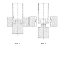
- Figures 1 and 2 are a cross-sectional view of a splitted punch according to the present invention in closed state ( Fig. 1 ), and in opened state ( Fig. 2 ), respectively.
Landscapes
- Engineering & Computer Science (AREA)
- Mechanical Engineering (AREA)
- General Engineering & Computer Science (AREA)
- Shaping Metal By Deep-Drawing, Or The Like (AREA)
- Press Drives And Press Lines (AREA)
- Forging (AREA)
Abstract
Description
- The present invention relates to a novel method for producing a gun cartridge casing.
- Typically gun cartridge cases are drawn from sheet metal discs in three 'stages'. First a cup is formed from the sheet metal disc. Thereafter the cup is drawn to the desired length by a number of forming operations through punches of decreasing diameters until a suitable length of the part is attained. The drawn part is then provided with a neck, if necessary. Finally, the bottom of the drawn and necked part is provided with a groove to form the final cartridge case.
- After each drawing stage the parts are annealed, pickled, rinsed and subjected to further quality improvement measures.
- For the annealing process the part should be clean, which requires a washing before the annealing. After the annealing the part is pickled, bondered and/or lubricated, which is required for the following drawing operations.
- Depending on the calibre, the drawing process is typically carried out in a transfer press, where the product is deep drawn in a number of sets comprising pairs of punches and dies (stations) to receive workpieces leaving a deep drawn tool. If the drawing is carried out in a transfer press, the transport is accomplished by using mechanical grippers.
- Normally a transfer press comprises 5 to 12 stations. Due to the heavy reduction in strength of the sheet, usually from an initial strength of about 3 to 4 mm to final strength of about 0.3 mm, the material is hardened. Further, the forming capability is reduced with every step. Therefore, the processes according to the state of the art require at least one further intermediate annealing process (incl. washing and pickling), sometimes depending on the calibre even more.
- After the ironing process in the transfer press there is necking process for most of the rifle cartridges. The necking is done after an annealing process to reduce the material stress before this critical forming process. Typically the necking is done in 2 stations.
- The groove and trim are formed using special equipment, which is separate from transfer press. For this to be achieved, the case is fixed in a collet chuck and turned while a shaped turning tool cuts the groove and a second one trims the length.
- It will readily be realised that such processes are laborious, costly, and require costly investments.
- It is therefore an object of the present invention to provide a method for producing a gun cartridge casing which can be performed on a single transfer press.
- There is provided a method for manufacturing a gun cartridge casing comprising the steps of:
- (a) providing a metal sheet to a multiple station deep drawing transfer press which comprises a blanking device for cutting blanks out of the metal sheet;
- (b) cutting a metal blanket of said metal sheet;
- (c) transferring said metal blanket obtained in step (b) to a first forming station which comprises a punch and a die, wherein said metal disc sheet is formed into a metal cup;
- (d1) transferring said metal cup obtained in step (c) to a second set of forming stations comprising a number of punches and dies, wherein said metal cup is deep drawn into an cartridge case; and
- (e1) releasing said cartridge case from the multiple station deep drawing transfer press,
- In an embodiment of the invention, the steps (b) of producing a blank from a metal sheet, and (c) of producing a cup are carried out in one cutting and forming station.
- If the cartridge case is to be provided with a groove, it is advantageously produced in a method for manufacturing a gun cartridge casing having a groove in a single multiple station deep drawing transfer press comprising the steps of:
- (d2) providing a metal cup to a set of forming stations in a multiple station deep drawing transfer press comprising a number of punches and dies, wherein said metal cup is deep drawn into a cartridge case; and
- (e2) transferring said metal cup obtained from step (d2) to a further forming station comprising a punch and a die, wherein the diameter of the bottom of said cartridge case is reduced to the required groove diameter;
- (f1) transferring said cartridge case having a bottom of reduced diameter obtained in step (e2) to a further forming station comprising a punch and a die to form a groove, wherein the die is a splitted die which can be opened after operation; and
- (g1) opening the splitted die and releasing the cartridge case provided with a groove from the multiple station deep drawing transfer press,
- Preferably, also the steps of cutting blanks of a metal sheet and forming a cup of the metal sheet are carried out in the same multiple station deep drawing transfer press in a sequence comprising the following steps:
- (a) providing a metal sheet to a multiple station deep drawing transfer press which comprises a blanking device for cutting blanks out of the metal sheet;
- (b) cutting a metal blanket of said metal sheet;
- (c) transferring said metal blanket obtained in step (b) to a first forming station which comprises a punch and a die,
- Some cartridge cases, particularly those used in rifles, require the presence of a neck. Also the neck is advantageously produced within the same multiple station deep drawing transfer press after step in a method for manufacturing a gun cartridge casing having a neck in a single multiple station deep drawing transfer press comprising the steps of:
- (d3) providing a metal cup to a set of forming stations in a multiple station deep drawing transfer press comprising a number of punches and dies, wherein said metal cup is deep drawn into a cartridge case; and
- (e3) transferring said cartridge case obtained in step (d3) to a further forming station, wherein said cartridge case is provided with a neck;
- (f2) and releasing the cartridge case from the multiple station deep drawing transfer press,
- Preferably, also the steps of cutting blanks of a metal sheet and forming a cup of the metal sheet are carried out in the same multiple station deep drawing transfer press in a sequence comprising the following steps:
- (a) providing a metal sheet to a multiple station deep drawing transfer press which comprises a blanking device for cutting blanks out of the metal sheet;
- (b) cutting a metal blanket of said metal sheet;
- (c) transferring said metal blanket obtained in step (b) to a first forming station which comprises a punch and a die,
- If a cartridge case having a groove and a neck is to be produced, then it may be produced in a method for manufacturing a gun cartridge casing having a neck in a single multiple station deep drawing transfer press comprising the steps of:
- (d4) providing a metal cup to a set of forming stations in a multiple station deep drawing transfer press comprising a number of punches and dies, wherein said metal cup is deep drawn into a cartridge case; and
- (e4) transferring said cartridge case obtained from step (d4) to a further forming station comprising a punch and a die, wherein the bottom of said cartridge case is reduced to the required groove diameter;
- (f3) transferring said cartridge case provided with a reduced bottom obtained in step (e2) to a further forming station comprising a punch and a die to form a groove, wherein the die is a splitted die which can be opened after operation; and;
- (g2) opening the splitted die and transferring said cartage case provided with a groove obtained in step (f2) to a further forming station, wherein said elongated metal cup is provided with a neck; and
- (h1) releasing the cartridge case from the multiple station deep drawing transfer press
- Preferably, also the steps of cutting blanks of a metal sheet and forming a cup of the metal sheet are carried out in the same multiple station deep drawing transfer press in a sequence comprising the following steps:
- (a) providing a metal sheet to a multiple station deep drawing transfer press which comprises a blanking device for cutting blanks out of the metal sheet;
- (b) cutting a metal blanket of said metal sheet;
- (c) transferring said metal blanket obtained in step (b) to a first forming station which comprises a punch and a die,
- If the cartridge case is to be equipped with a neck, such as in many rifle cartridge cases, it is desirable to produce it in the same multiple station deep drawing transfer press as all previous steps. In said machine, the neck is preferably produced at the very end of the process. Pistol cartridge cases are normally not provided with a neck.
- A forming station in the multiple station deep drawing transfer press usually comprises a pair of a punch and a die where the metal sheet is formed, first into a metal cup, and subsequently into a cartridge case with elongated form in relation to the metal cup, a stripper, an ejecter and a gripper which transports the cup of cartridge case from one forming station to the next one. In case a neck is formed, the forming station does not comprise a punch. There is just a die which forms a neck on the open side of the cartridge case and an inner pilot to maintain the wall thickness.
- According to the present invention there is also provided a multiple station deep drawing transfer press for manufacturing a gun cartridge casings in a single machine, which comprises a cutting device for cutting discs out of a metal sheet and a number of forming stations for drawing and forming said metal discs, wherein in at least one forming station comprising a punch and a die, the die exhibits a splitted punch to form a groove.
- According to the present invention, the metal sheet, which is preferably a brass sheet, is fed directly into a deep drawing transfer press. Preferably a zig-zag feeder for providing a multiple cut is used to feed the material to the cutting tool which cuts discs out of sheet metal. A zig-zag feeder will utilize the material in a most efficient manner without needless waste of material.
- Thereafter, a cup is formed in the transfer press, and the cup is transferred to subsequent stations of the transfer press, preferably without any intermediate washing, pickling and/or bondering. During various forming steps, the wall thickness of the case is reduced to a final wall thickness.
- To allow the further deep drawing and ironing operations without any annealing process to the final wall thickness, a reduction of the true strain of per operation is required. Preferably, according to the process of the present invention, the number of forming stations (pairs of punches and dies) is higher than in known processes. Preferably, the multiple station deep drawing transfer press used in the method according to the present invention comprises 12 to 25, preferably 15 to 25 forming stations in total. For Example, to include a neck, without any intermediate annealing step, the number of forming stations used for step (e3) is preferably from three to seven, most preferably from four to five.
- In step (c) the cup is preferably formed in one forming station, where the thickness of the metal is preferably reduced by 40% to 70% while a cup is formed.
- Preferably, the number of forming stations for carrying out drawing and forming steps (d) of the cup to form a cartridge case is from three to nine, more preferably from four to eight, such as from five to seven. In these forming stations, the wall thickness of the cup or of the intermediately drawn cases is preferably reduced by a higher percentage during the earlier stages of the drawing process of step (d) than in later stages of the step (d). For Example, according to a preferred embodiment the wall thickness of the cup is reduced by 30% to 50%, more preferably about 40% in a first forming station of step (d). While normally the reduction is about 60% to 70%.
- According to a further preferred embodiment, the wall thickness of the drawn case is reduced in a second forming station of step (d) by a lower percentage than in a first forming station of step (d). Preferably, the wall thickness of the drawn case is reduced by 20% to 30% in a second forming station of step (d).
- According to a still further preferred embodiment, the wall thickness of the drawn case is reduced in a third forming station of step (d) by a lower percentage than in a second forming station of step (d). Preferably, the wall thickness of the drawn case is reduced by 10% to 25%, preferably 10% to 20% in a third forming station of step (d). While normally the reduction is about 25% to 35%.
- According to a still further preferred embodiment, the wall thickness of the drawn case is reduced in a fourth and any further forming station of step (d) by an equal or a lower percentage than in a third forming station of step (d). Preferably, the wall thickness of the drawn case is reduced by 10% to 20% in a fourth or any further forming station of step (d).
- With the increasing number of forming stations and therefore with increasing bed size, the forming and coining force increases which may result in a winkling of the punch. The press force, depending on the caliber of the gun cartridge case, is preferably chosen between 75 to 250 tons, and a bed length is preferably from of 1000 to 3000 mm. Preferably, a ridged mechanical press or ideally a servo spindle press is used, which can actively correct the punch winkling.
- Preferably, one or two flash holes are pierced in the drawn case within the deep drawing transfer press.
- As described above, according to the state of the art, the grooving process is typically carried out in an external operation, in a turning method, wherein material is removed from the blank. The method according to the present invention, however, for the first time integrates the grooving steps in a transfer press, and does not remove material while the groove is formed.
- The groove is formed in two steps. For forming the groove, the first operation is a drawing operation where the bottom of the case is reduced in diameter to the required groove diameter. In a further station in the deep drawing transfer press, the bottom of the case is held with a splitted punch, then, the bottom and primer pocked are coined into the case. The material flows radially and, thus, the groove is formed. To release the case of the splitted punch, the punch is opened into its segments.
- This is further demonstrated by appending
Figures 1 and 2 , which are a cross-sectional view of a splitted punch according to the present invention in closed state (Fig. 1 ), and in opened state (Fig. 2 ), respectively.
Claims (14)
- A method for manufacturing a gun cartridge casing in a single multiple station deep drawing transfer press comprising the steps of:(a) providing a metal sheet to a multiple station deep drawing transfer press which comprises a blanking device for cutting blanks out of the metal sheet;(b) cutting a metal blanket of said metal sheet;(c) transferring said metal blanket obtained in step (b) to a first forming station which comprises a punch and a die, wherein said metal disc sheet is formed into a metal cup;(d1) transferring said metal cup obtained in step (c) to a second set of forming stations comprising a number of punches and dies, wherein said metal cup is deep drawn into an cartridge case; and(e1) releasing said cartridge case from the multiple station deep drawing transfer press,wherein between steps (a) and (e1), there are no intermediate washing, pickling and/or bondering steps.
- A method for manufacturing a gun cartridge casing having a groove in a single multiple station deep drawing transfer press comprising the steps of:(d2) providing a metal cup to a set of forming stations in a multiple station deep drawing transfer press comprising a number of punches and dies, wherein said metal cup is deep drawn into a cartridge case; and(e2) transferring said metal cup obtained from step (d2) to a further forming station comprising a punch and a die, wherein the diameter of the bottom of said cartridge case is reduced to the required groove diameter;(f1) transferring said cartridge case having a bottom of reduced diameter obtained in step (e2) to a further forming station comprising a punch and a die to form a groove, wherein the die is a splitted die which can be opened after operation; and(g1) opening the splitted die and releasing the cartridge case provided with a groove from the multiple station deep drawing transfer press,wherein between steps (d2) and (g1), there are no intermediate washing, pickling and/or bondering steps.
- The method according to claim 2, comprising the steps of:(a) providing a metal sheet to a multiple station deep drawing transfer press which comprises a blanking device for cutting blanks out of the metal sheet;(b) cutting a metal blanket of said metal sheet;(c) transferring said metal blanket obtained in step (b) to a first forming station which comprises a punch and a die, wherein said metal disc sheet is formed into a metal cup;whereupon the cup is transferred to step (d2), wherein between steps (a) and (h1), there are no intermediate washing, pickling and/or bondering steps.
- A method for manufacturing a gun cartridge casing having a neck in a single multiple station deep drawing transfer press comprising the steps of:(d3) providing a metal cup to a set of forming stations in a multiple station deep drawing transfer press comprising a number of punches and dies, wherein said metal cup is deep drawn into a cartridge case; and(e3) transferring said cartridge case obtained in step (d3) to a further forming station, wherein said cartridge case is provided with a neck;(f2) and releasing the cartridge case from the multiple station deep drawing transfer press,wherein between steps (d3) and (f2), there are no intermediate washing, pickling and/or bondering steps.
- The method according to claim 4, comprising the steps of:(a) providing a metal sheet to a multiple station deep drawing transfer press which comprises a blanking device for cutting blanks out of the metal sheet;(b) cutting a metal blanket of said metal sheet;(c) transferring said metal blanket obtained in step (b) to a first forming station which comprises a punch and a die, wherein said metal disc sheet is formed into a metal cup;whereupon the cup is transferred to step (d3), wherein between steps (a) and (f2), there are no intermediate washing, pickling and/or bondering steps.
- A method for manufacturing a gun cartridge casing having a neck in a single multiple station deep drawing transfer press comprising the steps of:(d4) providing a metal cup to a set of forming stations in a multiple station deep drawing transfer press comprising a number of punches and dies, wherein said metal cup is deep drawn into a cartridge case; and(e4) transferring said cartridge case obtained from step (d4) to a further forming station comprising a punch and a die, wherein the bottom of said cartridge case is reduced to the required groove diameter;(f3) transferring said cartridge case provided with a reduced bottom obtained in step (e2) to a further forming station comprising a punch and a die to form a groove, wherein the die is a splitted die which can be opened after operation; and;(g2) opening the splitted die and transferring said cartage case provided with a groove obtained in step (f2) to a further forming station, wherein said elongated metal cup is provided with a neck; and(h1) releasing the cartridge case from the multiple station deep drawing transfer presswherein between steps (d4) and (h1), there are no intermediate washing, pickling and/or bondering steps.
- The method according to claim 6, comprising the steps of:(a) providing a metal sheet to a multiple station deep drawing transfer press which comprises a blanking device for cutting blanks out of the metal sheet;(b) cutting a metal blanket of said metal sheet;(c) transferring said metal blanket obtained in step (b) to a first forming station which comprises a punch and a die, wherein said metal disc sheet is formed into a metal cup;whereupon the cup is transferred to step (d3), wherein between steps (a) and (h1), there are no intermediate washing, pickling and/or bondering steps.
- The method of any of the previous claims, wherein the metal sheet is of brass.
- The method of any of the previous claims, wherein said multiple station deep drawing transfer press comprises 12 to 25, preferably 15 to 25 pairs of punches and dies in total.
- The method of any of the previous claims, wherein said third set comprises three to five pairs of punches and dies for carrying out step (e).
- The method of any of the previous claims, wherein said multiple station deep drawing transfer press develops a press force between 75 and 250 tons.
- The method of any of the previous claims, wherein said multiple station deep drawing transfer press has a bed length between 1000 and 3000 mm.
- The method of any of the previous claims, wherein said multiple station deep drawing transfer press comprises a servo spindle press which actively corrects punch wrinkling.
- Multiple station deep drawing transfer press for manufacturing a gun cartridge casings in a single machine, which comprises a cutting device for cutting discs out of the metal sheet and a number of pairs of punches and dies for drawing said metal discs, wherein in at least one pair of a punch and a die, the die exhibits a splitted punch to form a groove.
Priority Applications (10)
| Application Number | Priority Date | Filing Date | Title |
|---|---|---|---|
| ES13162784.6T ES2637647T3 (en) | 2013-04-08 | 2013-04-08 | Method for producing a gun cartridge case, and a multi-station transfer press to carry out the method |
| PL13162784T PL2789411T3 (en) | 2013-04-08 | 2013-04-08 | Method for producing a gun cartridge casing and multiple station transfer press for carrying out the method |
| EP13162784.6A EP2789411B1 (en) | 2013-04-08 | 2013-04-08 | Method for producing a gun cartridge casing and multiple station transfer press for carrying out the method |
| DK13162784.6T DK2789411T3 (en) | 2013-04-08 | 2013-04-08 | Method of producing cartridge casings and multi-station deep draw transfer press to perform the method |
| IL230792A IL230792A0 (en) | 2013-04-08 | 2014-02-03 | Method for produing a gun cartridge casing |
| CA2843704A CA2843704A1 (en) | 2013-04-08 | 2014-02-26 | Method for producing a gun cartridge casing |
| JP2014060130A JP2014200845A (en) | 2013-04-08 | 2014-03-24 | Method for manufacturing cartridge for gun |
| ZA2014/02457A ZA201402457B (en) | 2013-04-08 | 2014-04-01 | Method for producing a gun cartridge casing |
| US14/245,338 US20140298979A1 (en) | 2013-04-08 | 2014-04-04 | Method for Producing a Gun Cartridge Casing |
| BR102014008262-0A BR102014008262A2 (en) | 2013-04-08 | 2014-04-04 | METHOD FOR PRODUCING A PISTOL CARTRIDGE CASE |
Applications Claiming Priority (1)
| Application Number | Priority Date | Filing Date | Title |
|---|---|---|---|
| EP13162784.6A EP2789411B1 (en) | 2013-04-08 | 2013-04-08 | Method for producing a gun cartridge casing and multiple station transfer press for carrying out the method |
Publications (2)
| Publication Number | Publication Date |
|---|---|
| EP2789411A1 true EP2789411A1 (en) | 2014-10-15 |
| EP2789411B1 EP2789411B1 (en) | 2017-05-17 |
Family
ID=48092733
Family Applications (1)
| Application Number | Title | Priority Date | Filing Date |
|---|---|---|---|
| EP13162784.6A Not-in-force EP2789411B1 (en) | 2013-04-08 | 2013-04-08 | Method for producing a gun cartridge casing and multiple station transfer press for carrying out the method |
Country Status (10)
| Country | Link |
|---|---|
| US (1) | US20140298979A1 (en) |
| EP (1) | EP2789411B1 (en) |
| JP (1) | JP2014200845A (en) |
| BR (1) | BR102014008262A2 (en) |
| CA (1) | CA2843704A1 (en) |
| DK (1) | DK2789411T3 (en) |
| ES (1) | ES2637647T3 (en) |
| IL (1) | IL230792A0 (en) |
| PL (1) | PL2789411T3 (en) |
| ZA (1) | ZA201402457B (en) |
Cited By (1)
| Publication number | Priority date | Publication date | Assignee | Title |
|---|---|---|---|---|
| WO2023046559A3 (en) * | 2021-09-21 | 2023-06-15 | Ruag Ammotec Ag | Method and tool for producing a base piece of a multi-part cartridge case, base piece and cartridge case |
Families Citing this family (4)
| Publication number | Priority date | Publication date | Assignee | Title |
|---|---|---|---|---|
| US10495430B2 (en) | 2017-03-07 | 2019-12-03 | National Machinery Llc | Long cartridge case |
| EP3765812B1 (en) | 2018-03-13 | 2024-04-24 | BAE SYSTEMS plc | Improved metal head unit for use with a polymer case to form a cartridge |
| GB2571951B (en) * | 2018-03-13 | 2022-04-20 | Bae Systems Plc | Improved pressed head |
| KR102759338B1 (en) * | 2022-11-11 | 2025-01-23 | 주식회사 풍산홀딩스 | Manufacturing device for cartridge case |
Citations (4)
| Publication number | Priority date | Publication date | Assignee | Title |
|---|---|---|---|---|
| GB433829A (en) * | 1933-08-22 | 1935-08-21 | Oreste Biginelli | The production of tubular metal cases such as cartridge cases |
| US2397370A (en) * | 1942-11-17 | 1946-03-26 | Raleigh Cycle Company Ltd | Manufacture of cartridge cases and the like |
| US3408718A (en) * | 1966-06-16 | 1968-11-05 | Trw Inc | Method of manufacturing cartridge cases and article of manufacture |
| FR2544068A1 (en) * | 1983-04-05 | 1984-10-12 | Lachaussee Sa Ets | Process for producing a cartridge case with central percussion and cartridge case so produced |
Family Cites Families (1)
| Publication number | Priority date | Publication date | Assignee | Title |
|---|---|---|---|---|
| GB1602973A (en) * | 1977-07-07 | 1981-11-18 | Spence G M | Process for producing tubular articles |
-
2013
- 2013-04-08 PL PL13162784T patent/PL2789411T3/en unknown
- 2013-04-08 DK DK13162784.6T patent/DK2789411T3/en active
- 2013-04-08 ES ES13162784.6T patent/ES2637647T3/en active Active
- 2013-04-08 EP EP13162784.6A patent/EP2789411B1/en not_active Not-in-force
-
2014
- 2014-02-03 IL IL230792A patent/IL230792A0/en unknown
- 2014-02-26 CA CA2843704A patent/CA2843704A1/en not_active Abandoned
- 2014-03-24 JP JP2014060130A patent/JP2014200845A/en active Pending
- 2014-04-01 ZA ZA2014/02457A patent/ZA201402457B/en unknown
- 2014-04-04 BR BR102014008262-0A patent/BR102014008262A2/en not_active IP Right Cessation
- 2014-04-04 US US14/245,338 patent/US20140298979A1/en not_active Abandoned
Patent Citations (4)
| Publication number | Priority date | Publication date | Assignee | Title |
|---|---|---|---|---|
| GB433829A (en) * | 1933-08-22 | 1935-08-21 | Oreste Biginelli | The production of tubular metal cases such as cartridge cases |
| US2397370A (en) * | 1942-11-17 | 1946-03-26 | Raleigh Cycle Company Ltd | Manufacture of cartridge cases and the like |
| US3408718A (en) * | 1966-06-16 | 1968-11-05 | Trw Inc | Method of manufacturing cartridge cases and article of manufacture |
| FR2544068A1 (en) * | 1983-04-05 | 1984-10-12 | Lachaussee Sa Ets | Process for producing a cartridge case with central percussion and cartridge case so produced |
Cited By (1)
| Publication number | Priority date | Publication date | Assignee | Title |
|---|---|---|---|---|
| WO2023046559A3 (en) * | 2021-09-21 | 2023-06-15 | Ruag Ammotec Ag | Method and tool for producing a base piece of a multi-part cartridge case, base piece and cartridge case |
Also Published As
| Publication number | Publication date |
|---|---|
| BR102014008262A2 (en) | 2014-12-23 |
| JP2014200845A (en) | 2014-10-27 |
| PL2789411T3 (en) | 2017-10-31 |
| EP2789411B1 (en) | 2017-05-17 |
| US20140298979A1 (en) | 2014-10-09 |
| IL230792A0 (en) | 2014-08-31 |
| ES2637647T3 (en) | 2017-10-16 |
| ZA201402457B (en) | 2017-08-30 |
| DK2789411T3 (en) | 2017-09-11 |
| CA2843704A1 (en) | 2014-10-08 |
Similar Documents
| Publication | Publication Date | Title |
|---|---|---|
| EP2789411B1 (en) | Method for producing a gun cartridge casing and multiple station transfer press for carrying out the method | |
| EP3372324B1 (en) | Long cartridge case | |
| EP2900398B1 (en) | Precision forged cartridge case | |
| EP3248704B1 (en) | Flanging method | |
| US2371716A (en) | Method of making cartridge cases and the like | |
| JP5373378B2 (en) | Forging method | |
| US11480416B2 (en) | Method for producing multi-component cases | |
| US2969030A (en) | Production of writing tips | |
| US7334447B1 (en) | Nacelle nose cap forming method and apparatus | |
| CN211727276U (en) | Punch forming mechanism for forming aluminum ring | |
| EP2759358A1 (en) | Method of making a forged part | |
| US2762108A (en) | Method for forming shell blanks | |
| US9718118B2 (en) | Forging apparatus | |
| US9566641B2 (en) | Forging apparatus | |
| EP2745953B1 (en) | A forging apparatus | |
| EP4663318A1 (en) | Long cartridge case - method of forming a closed end metal tube | |
| US1691878A (en) | Metal working | |
| US20220111431A1 (en) | Device With Multiple Coined Areas Having Multiple Mechanical Properties | |
| JP2007136529A (en) | Manufacturing method of high precision ring | |
| CN217775471U (en) | For military use bearing blank forges mould subassembly | |
| AU2020102626A4 (en) | Design of Progressive Tools | |
| CN105458630A (en) | Manufacturing method for intermediate blank of F22 alloy bell-shaped cartridge receiver forged piece | |
| KR101779894B1 (en) | Method for manufacturing pem nut | |
| CN106345899A (en) | Automobile trailing arm support machining process | |
| HK1217311A1 (en) | Cut-off end surface improvement |
Legal Events
| Date | Code | Title | Description |
|---|---|---|---|
| PUAI | Public reference made under article 153(3) epc to a published international application that has entered the european phase |
Free format text: ORIGINAL CODE: 0009012 |
|
| 17P | Request for examination filed |
Effective date: 20130408 |
|
| AK | Designated contracting states |
Kind code of ref document: A1 Designated state(s): AL AT BE BG CH CY CZ DE DK EE ES FI FR GB GR HR HU IE IS IT LI LT LU LV MC MK MT NL NO PL PT RO RS SE SI SK SM TR |
|
| AX | Request for extension of the european patent |
Extension state: BA ME |
|
| 17Q | First examination report despatched |
Effective date: 20160621 |
|
| GRAP | Despatch of communication of intention to grant a patent |
Free format text: ORIGINAL CODE: EPIDOSNIGR1 |
|
| INTG | Intention to grant announced |
Effective date: 20161121 |
|
| GRAJ | Information related to disapproval of communication of intention to grant by the applicant or resumption of examination proceedings by the epo deleted |
Free format text: ORIGINAL CODE: EPIDOSDIGR1 |
|
| GRAP | Despatch of communication of intention to grant a patent |
Free format text: ORIGINAL CODE: EPIDOSNIGR1 |
|
| INTC | Intention to grant announced (deleted) | ||
| INTG | Intention to grant announced |
Effective date: 20170201 |
|
| GRAS | Grant fee paid |
Free format text: ORIGINAL CODE: EPIDOSNIGR3 |
|
| GRAA | (expected) grant |
Free format text: ORIGINAL CODE: 0009210 |
|
| AK | Designated contracting states |
Kind code of ref document: B1 Designated state(s): AL AT BE BG CH CY CZ DE DK EE ES FI FR GB GR HR HU IE IS IT LI LT LU LV MC MK MT NL NO PL PT RO RS SE SI SK SM TR |
|
| REG | Reference to a national code |
Ref country code: GB Ref legal event code: FG4D |
|
| REG | Reference to a national code |
Ref country code: CH Ref legal event code: EP Ref country code: CH Ref legal event code: NV Representative=s name: R.A. EGLI AND CO, PATENTANWAELTE, CH |
|
| REG | Reference to a national code |
Ref country code: IE Ref legal event code: FG4D |
|
| REG | Reference to a national code |
Ref country code: AT Ref legal event code: REF Ref document number: 894002 Country of ref document: AT Kind code of ref document: T Effective date: 20170615 |
|
| REG | Reference to a national code |
Ref country code: SE Ref legal event code: TRGR |
|
| REG | Reference to a national code |
Ref country code: DE Ref legal event code: R096 Ref document number: 602013021160 Country of ref document: DE |
|
| REG | Reference to a national code |
Ref country code: NL Ref legal event code: FP |
|
| REG | Reference to a national code |
Ref country code: DK Ref legal event code: T3 Effective date: 20170905 |
|
| REG | Reference to a national code |
Ref country code: NO Ref legal event code: T2 Effective date: 20170517 |
|
| REG | Reference to a national code |
Ref country code: LT Ref legal event code: MG4D |
|
| REG | Reference to a national code |
Ref country code: AT Ref legal event code: MK05 Ref document number: 894002 Country of ref document: AT Kind code of ref document: T Effective date: 20170517 |
|
| REG | Reference to a national code |
Ref country code: ES Ref legal event code: FG2A Ref document number: 2637647 Country of ref document: ES Kind code of ref document: T3 Effective date: 20171016 |
|
| PG25 | Lapsed in a contracting state [announced via postgrant information from national office to epo] |
Ref country code: HR Free format text: LAPSE BECAUSE OF FAILURE TO SUBMIT A TRANSLATION OF THE DESCRIPTION OR TO PAY THE FEE WITHIN THE PRESCRIBED TIME-LIMIT Effective date: 20170517 Ref country code: AT Free format text: LAPSE BECAUSE OF FAILURE TO SUBMIT A TRANSLATION OF THE DESCRIPTION OR TO PAY THE FEE WITHIN THE PRESCRIBED TIME-LIMIT Effective date: 20170517 Ref country code: GR Free format text: LAPSE BECAUSE OF FAILURE TO SUBMIT A TRANSLATION OF THE DESCRIPTION OR TO PAY THE FEE WITHIN THE PRESCRIBED TIME-LIMIT Effective date: 20170818 Ref country code: LT Free format text: LAPSE BECAUSE OF FAILURE TO SUBMIT A TRANSLATION OF THE DESCRIPTION OR TO PAY THE FEE WITHIN THE PRESCRIBED TIME-LIMIT Effective date: 20170517 |
|
| PG25 | Lapsed in a contracting state [announced via postgrant information from national office to epo] |
Ref country code: IS Free format text: LAPSE BECAUSE OF FAILURE TO SUBMIT A TRANSLATION OF THE DESCRIPTION OR TO PAY THE FEE WITHIN THE PRESCRIBED TIME-LIMIT Effective date: 20170917 Ref country code: LV Free format text: LAPSE BECAUSE OF FAILURE TO SUBMIT A TRANSLATION OF THE DESCRIPTION OR TO PAY THE FEE WITHIN THE PRESCRIBED TIME-LIMIT Effective date: 20170517 Ref country code: RS Free format text: LAPSE BECAUSE OF FAILURE TO SUBMIT A TRANSLATION OF THE DESCRIPTION OR TO PAY THE FEE WITHIN THE PRESCRIBED TIME-LIMIT Effective date: 20170517 Ref country code: BG Free format text: LAPSE BECAUSE OF FAILURE TO SUBMIT A TRANSLATION OF THE DESCRIPTION OR TO PAY THE FEE WITHIN THE PRESCRIBED TIME-LIMIT Effective date: 20170817 |
|
| PG25 | Lapsed in a contracting state [announced via postgrant information from national office to epo] |
Ref country code: SK Free format text: LAPSE BECAUSE OF FAILURE TO SUBMIT A TRANSLATION OF THE DESCRIPTION OR TO PAY THE FEE WITHIN THE PRESCRIBED TIME-LIMIT Effective date: 20170517 Ref country code: RO Free format text: LAPSE BECAUSE OF FAILURE TO SUBMIT A TRANSLATION OF THE DESCRIPTION OR TO PAY THE FEE WITHIN THE PRESCRIBED TIME-LIMIT Effective date: 20170517 Ref country code: EE Free format text: LAPSE BECAUSE OF FAILURE TO SUBMIT A TRANSLATION OF THE DESCRIPTION OR TO PAY THE FEE WITHIN THE PRESCRIBED TIME-LIMIT Effective date: 20170517 |
|
| REG | Reference to a national code |
Ref country code: DE Ref legal event code: R097 Ref document number: 602013021160 Country of ref document: DE |
|
| PG25 | Lapsed in a contracting state [announced via postgrant information from national office to epo] |
Ref country code: SM Free format text: LAPSE BECAUSE OF FAILURE TO SUBMIT A TRANSLATION OF THE DESCRIPTION OR TO PAY THE FEE WITHIN THE PRESCRIBED TIME-LIMIT Effective date: 20170517 |
|
| PLBE | No opposition filed within time limit |
Free format text: ORIGINAL CODE: 0009261 |
|
| STAA | Information on the status of an ep patent application or granted ep patent |
Free format text: STATUS: NO OPPOSITION FILED WITHIN TIME LIMIT |
|
| 26N | No opposition filed |
Effective date: 20180220 |
|
| PG25 | Lapsed in a contracting state [announced via postgrant information from national office to epo] |
Ref country code: SI Free format text: LAPSE BECAUSE OF FAILURE TO SUBMIT A TRANSLATION OF THE DESCRIPTION OR TO PAY THE FEE WITHIN THE PRESCRIBED TIME-LIMIT Effective date: 20170517 |
|
| REG | Reference to a national code |
Ref country code: DE Ref legal event code: R119 Ref document number: 602013021160 Country of ref document: DE |
|
| REG | Reference to a national code |
Ref country code: DK Ref legal event code: EBP Effective date: 20180430 Ref country code: NO Ref legal event code: MMEP |
|
| PG25 | Lapsed in a contracting state [announced via postgrant information from national office to epo] |
Ref country code: MC Free format text: LAPSE BECAUSE OF FAILURE TO SUBMIT A TRANSLATION OF THE DESCRIPTION OR TO PAY THE FEE WITHIN THE PRESCRIBED TIME-LIMIT Effective date: 20170517 Ref country code: CZ Free format text: LAPSE BECAUSE OF NON-PAYMENT OF DUE FEES Effective date: 20180408 |
|
| REG | Reference to a national code |
Ref country code: CH Ref legal event code: PL |
|
| REG | Reference to a national code |
Ref country code: SE Ref legal event code: EUG |
|
| REG | Reference to a national code |
Ref country code: NL Ref legal event code: MM Effective date: 20180501 |
|
| REG | Reference to a national code |
Ref country code: BE Ref legal event code: MM Effective date: 20180430 |
|
| GBPC | Gb: european patent ceased through non-payment of renewal fee |
Effective date: 20180408 |
|
| REG | Reference to a national code |
Ref country code: IE Ref legal event code: MM4A |
|
| PG25 | Lapsed in a contracting state [announced via postgrant information from national office to epo] |
Ref country code: DE Free format text: LAPSE BECAUSE OF NON-PAYMENT OF DUE FEES Effective date: 20181101 Ref country code: SE Free format text: LAPSE BECAUSE OF NON-PAYMENT OF DUE FEES Effective date: 20180409 Ref country code: NO Free format text: LAPSE BECAUSE OF NON-PAYMENT OF DUE FEES Effective date: 20180430 Ref country code: FI Free format text: LAPSE BECAUSE OF NON-PAYMENT OF DUE FEES Effective date: 20180408 Ref country code: NL Free format text: LAPSE BECAUSE OF NON-PAYMENT OF DUE FEES Effective date: 20180501 Ref country code: LU Free format text: LAPSE BECAUSE OF NON-PAYMENT OF DUE FEES Effective date: 20180408 |
|
| PG25 | Lapsed in a contracting state [announced via postgrant information from national office to epo] |
Ref country code: BE Free format text: LAPSE BECAUSE OF NON-PAYMENT OF DUE FEES Effective date: 20180430 Ref country code: CH Free format text: LAPSE BECAUSE OF NON-PAYMENT OF DUE FEES Effective date: 20180430 Ref country code: LI Free format text: LAPSE BECAUSE OF NON-PAYMENT OF DUE FEES Effective date: 20180430 Ref country code: GB Free format text: LAPSE BECAUSE OF NON-PAYMENT OF DUE FEES Effective date: 20180408 |
|
| PG25 | Lapsed in a contracting state [announced via postgrant information from national office to epo] |
Ref country code: FR Free format text: LAPSE BECAUSE OF NON-PAYMENT OF DUE FEES Effective date: 20180430 Ref country code: IT Free format text: LAPSE BECAUSE OF NON-PAYMENT OF DUE FEES Effective date: 20180408 Ref country code: IE Free format text: LAPSE BECAUSE OF NON-PAYMENT OF DUE FEES Effective date: 20180408 |
|
| PG25 | Lapsed in a contracting state [announced via postgrant information from national office to epo] |
Ref country code: DK Free format text: LAPSE BECAUSE OF NON-PAYMENT OF DUE FEES Effective date: 20180430 |
|
| REG | Reference to a national code |
Ref country code: ES Ref legal event code: FD2A Effective date: 20190911 |
|
| PG25 | Lapsed in a contracting state [announced via postgrant information from national office to epo] |
Ref country code: ES Free format text: LAPSE BECAUSE OF NON-PAYMENT OF DUE FEES Effective date: 20180409 |
|
| PG25 | Lapsed in a contracting state [announced via postgrant information from national office to epo] |
Ref country code: MT Free format text: LAPSE BECAUSE OF NON-PAYMENT OF DUE FEES Effective date: 20180408 |
|
| PG25 | Lapsed in a contracting state [announced via postgrant information from national office to epo] |
Ref country code: PL Free format text: LAPSE BECAUSE OF NON-PAYMENT OF DUE FEES Effective date: 20180408 |
|
| PG25 | Lapsed in a contracting state [announced via postgrant information from national office to epo] |
Ref country code: TR Free format text: LAPSE BECAUSE OF FAILURE TO SUBMIT A TRANSLATION OF THE DESCRIPTION OR TO PAY THE FEE WITHIN THE PRESCRIBED TIME-LIMIT Effective date: 20170517 |
|
| PG25 | Lapsed in a contracting state [announced via postgrant information from national office to epo] |
Ref country code: HU Free format text: LAPSE BECAUSE OF FAILURE TO SUBMIT A TRANSLATION OF THE DESCRIPTION OR TO PAY THE FEE WITHIN THE PRESCRIBED TIME-LIMIT; INVALID AB INITIO Effective date: 20130408 Ref country code: PT Free format text: LAPSE BECAUSE OF FAILURE TO SUBMIT A TRANSLATION OF THE DESCRIPTION OR TO PAY THE FEE WITHIN THE PRESCRIBED TIME-LIMIT Effective date: 20170517 |
|
| PG25 | Lapsed in a contracting state [announced via postgrant information from national office to epo] |
Ref country code: CY Free format text: LAPSE BECAUSE OF FAILURE TO SUBMIT A TRANSLATION OF THE DESCRIPTION OR TO PAY THE FEE WITHIN THE PRESCRIBED TIME-LIMIT Effective date: 20170517 Ref country code: MK Free format text: LAPSE BECAUSE OF NON-PAYMENT OF DUE FEES Effective date: 20170517 |
|
| PG25 | Lapsed in a contracting state [announced via postgrant information from national office to epo] |
Ref country code: AL Free format text: LAPSE BECAUSE OF FAILURE TO SUBMIT A TRANSLATION OF THE DESCRIPTION OR TO PAY THE FEE WITHIN THE PRESCRIBED TIME-LIMIT Effective date: 20170517 |