EP2789368A1 - Leadless pacemaker - Google Patents
Leadless pacemaker Download PDFInfo
- Publication number
- EP2789368A1 EP2789368A1 EP14162987.3A EP14162987A EP2789368A1 EP 2789368 A1 EP2789368 A1 EP 2789368A1 EP 14162987 A EP14162987 A EP 14162987A EP 2789368 A1 EP2789368 A1 EP 2789368A1
- Authority
- EP
- European Patent Office
- Prior art keywords
- fixation
- housing
- free end
- pacemaker
- leadless pacemaker
- Prior art date
- Legal status (The legal status is an assumption and is not a legal conclusion. Google has not performed a legal analysis and makes no representation as to the accuracy of the status listed.)
- Granted
Links
- 230000007246 mechanism Effects 0.000 claims abstract description 22
- 210000005003 heart tissue Anatomy 0.000 claims abstract description 18
- 229910001220 stainless steel Inorganic materials 0.000 claims description 3
- 239000010935 stainless steel Substances 0.000 claims description 3
- HLXZNVUGXRDIFK-UHFFFAOYSA-N nickel titanium Chemical compound [Ti].[Ti].[Ti].[Ti].[Ti].[Ti].[Ti].[Ti].[Ti].[Ti].[Ti].[Ni].[Ni].[Ni].[Ni].[Ni].[Ni].[Ni].[Ni].[Ni].[Ni].[Ni].[Ni].[Ni].[Ni] HLXZNVUGXRDIFK-UHFFFAOYSA-N 0.000 claims description 2
- 229910001000 nickel titanium Inorganic materials 0.000 claims description 2
- 239000000463 material Substances 0.000 description 6
- 230000000747 cardiac effect Effects 0.000 description 5
- 210000001519 tissue Anatomy 0.000 description 4
- 241000242722 Cestoda Species 0.000 description 3
- 230000006378 damage Effects 0.000 description 3
- 238000000034 method Methods 0.000 description 3
- 238000004873 anchoring Methods 0.000 description 2
- 238000013461 design Methods 0.000 description 2
- 238000002513 implantation Methods 0.000 description 2
- 239000011347 resin Substances 0.000 description 2
- 229920005989 resin Polymers 0.000 description 2
- 230000000638 stimulation Effects 0.000 description 2
- 241000124008 Mammalia Species 0.000 description 1
- 208000010378 Pulmonary Embolism Diseases 0.000 description 1
- 206010049447 Tachyarrhythmia Diseases 0.000 description 1
- 208000001871 Tachycardia Diseases 0.000 description 1
- 238000013459 approach Methods 0.000 description 1
- 230000001746 atrial effect Effects 0.000 description 1
- 230000000903 blocking effect Effects 0.000 description 1
- 238000010276 construction Methods 0.000 description 1
- 230000008602 contraction Effects 0.000 description 1
- 230000002950 deficient Effects 0.000 description 1
- 230000002542 deteriorative effect Effects 0.000 description 1
- 238000011161 development Methods 0.000 description 1
- 208000015181 infectious disease Diseases 0.000 description 1
- 208000014674 injury Diseases 0.000 description 1
- 210000000936 intestine Anatomy 0.000 description 1
- 238000004519 manufacturing process Methods 0.000 description 1
- 238000012986 modification Methods 0.000 description 1
- 230000004048 modification Effects 0.000 description 1
- 231100000241 scar Toxicity 0.000 description 1
- 230000001360 synchronised effect Effects 0.000 description 1
- 230000000451 tissue damage Effects 0.000 description 1
- 231100000827 tissue damage Toxicity 0.000 description 1
- 230000008733 trauma Effects 0.000 description 1
- 230000002861 ventricular Effects 0.000 description 1
Images


Classifications
-
- A—HUMAN NECESSITIES
- A61—MEDICAL OR VETERINARY SCIENCE; HYGIENE
- A61N—ELECTROTHERAPY; MAGNETOTHERAPY; RADIATION THERAPY; ULTRASOUND THERAPY
- A61N1/00—Electrotherapy; Circuits therefor
- A61N1/02—Details
- A61N1/04—Electrodes
- A61N1/05—Electrodes for implantation or insertion into the body, e.g. heart electrode
- A61N1/0587—Epicardial electrode systems; Endocardial electrodes piercing the pericardium
- A61N1/059—Anchoring means
-
- A—HUMAN NECESSITIES
- A61—MEDICAL OR VETERINARY SCIENCE; HYGIENE
- A61N—ELECTROTHERAPY; MAGNETOTHERAPY; RADIATION THERAPY; ULTRASOUND THERAPY
- A61N1/00—Electrotherapy; Circuits therefor
- A61N1/18—Applying electric currents by contact electrodes
- A61N1/32—Applying electric currents by contact electrodes alternating or intermittent currents
- A61N1/36—Applying electric currents by contact electrodes alternating or intermittent currents for stimulation
- A61N1/372—Arrangements in connection with the implantation of stimulators
- A61N1/375—Constructional arrangements, e.g. casings
- A61N1/3756—Casings with electrodes thereon, e.g. leadless stimulators
-
- A—HUMAN NECESSITIES
- A61—MEDICAL OR VETERINARY SCIENCE; HYGIENE
- A61N—ELECTROTHERAPY; MAGNETOTHERAPY; RADIATION THERAPY; ULTRASOUND THERAPY
- A61N1/00—Electrotherapy; Circuits therefor
- A61N1/02—Details
- A61N1/04—Electrodes
- A61N1/05—Electrodes for implantation or insertion into the body, e.g. heart electrode
- A61N1/056—Transvascular endocardial electrode systems
- A61N1/057—Anchoring means; Means for fixing the head inside the heart
-
- A—HUMAN NECESSITIES
- A61—MEDICAL OR VETERINARY SCIENCE; HYGIENE
- A61N—ELECTROTHERAPY; MAGNETOTHERAPY; RADIATION THERAPY; ULTRASOUND THERAPY
- A61N1/00—Electrotherapy; Circuits therefor
- A61N1/18—Applying electric currents by contact electrodes
- A61N1/32—Applying electric currents by contact electrodes alternating or intermittent currents
- A61N1/36—Applying electric currents by contact electrodes alternating or intermittent currents for stimulation
- A61N1/372—Arrangements in connection with the implantation of stimulators
- A61N1/37205—Microstimulators, e.g. implantable through a cannula
Definitions
- the present disclosure relates to leadless cardiac pacemakers and, more particularly, to features and methods by which they are attached to heart tissue. More specifically, the present disclosure relates to features for attaching a leadless cardiac pacemaker to heart tissue with a radial fixation mechanism.
- Cardiac pacemakers provide an electrical stimulation of the heart when its own natural stimuli generation and/or conduction system failed to provide synchronized atrial and ventricular contractions at rates sufficient for a mammal's health. Furthermore, cardiac pacemakers may provide electrical overdrive stimulation to suppress or convert tachyarrhythmia.
- pacemakers are known as leadless pacemakers, as they do not require a pacing lead for connecting the electronics package to the pacing electrode. Instead, the pacing electrode is disposed on a distal portion of the housing.
- the leadless type pacemaker can solve typical problems with pacing leads, e.g. that they become a site of infection and morbidity or that they can become defective, thus deteriorating the pacemakers performance or even blocking the delivery of pacing pulses at all.
- a leadless pacemaker comprising a hermetic housing, a pacing electrode disposed on a distal portion of the housing, an electronics package disposed in the housing and configured to generate and deliver pacing pulses to the pacing electrode, and a fixation mechanism, arranged on the distal portion of the housing, wherein the fixation mechanism comprises at least one deformable hook-shaped thin fixation wire having an attachment portion fixedly attached at the distal portion of the housing and a free end portion which is angled or bent with respect to the attachment portion such that it extends essentially in conformity but with a small spacing to a neighboured surface portion of the housing such that the free end portion engages with heart tissue onto which the distal portion of the housing is pressed, upon rotation of the pacemaker in that direction in which the free end portion extends from the attachment portion, and disengages upon rotation of the pacemaker in the opposite direction.
- tapeworms use many small teeth anchor themselves to the wall of the intestine.
- One tapeworm species has all of the teeth angled in the same direction allowing it to disengage by moving its head in the opposite direction. The teeth simply slide out of their holes.
- the leadless pacemaker of the present invention is advantageous in so far as it can be easily placed by the physician, remain in place for the life of the pacemaker and can be removed with minimal tissue damage. More specifically, at least in some embodiments the disclosed fixation mechanism provides for sufficient fixation in a short time after implantation and avoids that the device comes free and causes a pulmonary embolism. Compared to prior passive fixation mechanisms and methods, the fixation mechanism disclosed herein avoids an undue entrenching in scar tissue and enables a sufficiently easy disengagement from that tissue. Compared to prior art combinations of passive and active fixation mechanisms, the mechanism disclosed herein provides a simple fixation means and avoids an undue complexity or unduly large dimensions beyond the desired design envelope.
- the fixation mechanism comprises a plurality of separate hook-shaped fixation wires, wherein the fixation wires are arranged such that the free end portions thereof essentially form segments of a closed curve, in particular a circle or an ellipse, the ends of each of the wires slightly protruding from the closed curve in a distal direction.
- the fixation mechanism comprises a plurality of separate hook-shaped fixation wires, wherein the fixation wires are arranged such that the free end portions thereof extend obliquely from a virtual inner closed curve, in particular a circle or an ellipse, accommodating the most inner points of the free end portions of all fixation wires to a virtual outer closed curve, in particular a circle or an ellipse, accommodating the end tips of all fixation wires.
- the or each fixation wire when a proximal force is exerted on the pacemaker in its state fixed to heart tissue, is deformable such that its end portion bends to adopt to the direction of the proximal force and slides out of the heart tissue without damaging it.
- the or each fixation wire comprises a central attachment portion and two free end portions, each extending from one end of the central attachment portion.
- the or each fixation wire or, more precisely, a projection of the or each fixation wire on a plane on which a longitudinal axis of the housing stands orthogonally is approximately S-shaped.
- the leadless pacemaker of the present invention comprises 2 to 12 fixation wires each having one free end portion.
- the fixation mechanism of the present invention contains a number of small wire tines which protrude from the header of the device and curve in the tangential direction relative to the diameter of the device.
- the number of tines is variable, but preferably as few as two tines (or free end portions) is sufficient and as many as 12 tines (or free end portions) is possible depending on device weight, wire diameter, and wire material.
- the tines engage with the heart tissue by clockwise rotation of the device during implantation.
- the tines release from the heart by counter clockwise rotation. If tines fail to disengage from rotation, device can be removed from the heart by sufficient force at which the tines will deform to slide out of the heart tissue without causing significant damage.
- the attachment portion of the or each fixation wire is moulded into a resin-moulded distal housing portion.
- the housing can comprise a cylindrical or cask shaped body housing most of the electronics package, and the distal housing portion can be conical or bell-shaped, and the or each free end portion of each fixation wire extends tangentially or obliquely close to the end face of the conical or bell-shaped housing portion.
- the header is bell shaped with a diameter equal to that of the hermetical can, and narrowing down to 4 mm at 2 mm from the end of the can.
- the tines exist in a horizontal plane 1.0 to 1.5 mm from the end of the hermetic can.
- the or at least one fixation wire forms the only or one pacing electrode.
- the pacing electrode can either be one or more of the tines, or a separate post protruding from the header along the long axis of the device.
- the or each fixation wire is bent two-dimensionally with its attachment portion bent rearward from the or each free end portion. More specifically, the rearwardly bent attachment portion is that portion which is covered with the resin of a resin-moulded distal housing portion mentioned further above.
- fixation wires are those which have two free end portions, between 1 and 6, preferably 1 or 2, such fixation wires can be provided in the fixation mechanism.
- the fixation wires are arranged such that the plane of the closed curve or virtual inner and outer closed curve is between 0.5 and 2.5 mm, preferably between 1 and 2 mm, proximal with respect to the end face of the distal housing portion or hermetic can, respectively.
- This is provided as anchoring systems which extend past the current outer diameter of the device during passage through the introducer are unacceptable due to the dimensional constraints that already exist. Therefore, the fixation mechanism disclosed herein fits within the diameter of the device until deployment. Additionally, the fixture must not extend more than 5 mm from the base of the hermetic can during delivery or the fixture must be flexible.
- the or each fixation wire is made from stainless steel, in particular from 316L stainless steel, or Nitinol.
- the diameter of the or each fixation wire is between 0.1 and 0.5 mm, preferably between 0.15 and 0.38 mm.
- the number, thickness, and material of the tines are interdependent and can be chosen by one of ordinary skill in the art according to the dimensions, weight, and specific requirements of the respective pacemaker.
- Figs. 1A to 1C show, as an embodiment of the invention, a leadless pacemaker 10 which has a basically cylindrical housing 11 for accommodating an electronics package (not shown).
- the housing 11 has a distal end portion 11a formed as a resin-moulded cap which is essentially bell-shaped.
- a tip-shaped pacing electrode 13 protrudes distally from the housing 11.
- Two fixation wires 15 which are essentially S-shaped are, in their central portions, embedded in the resin material of the cap 11a, whereas end portions 15b, 15c thereof almost tangentially (slightly inclined with respect to the periphery of the cap 11a) extend from both ends of the central portion.
- the central portion can be designated as attachment portion.
- the free end portions 15b, 15c would engage with heart tissue against which the distal end of the pacemaker is pressed, the free end portions could be designated as engagement or fixation portions, respectively. It is to be understood that upon anti-clockwise rotation of the pacemaker the free end portions of the fixation wires 15, once in engagement with heart tissue, would gradually disengage from such tissue.
- the material and dimensions of the fixation wires are selected such that even pulling the pacemaker away from the heart tissue basically along its long axis would result in disengagement of the free end portions from the heart tissue, without significant damage thereof.
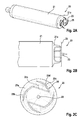
- Figs. 2A to 2C show a leadless pacemaker 20 according to a further embodiment of the invention.
- the pacemaker 20 has a cylindrical housing 21 and a distal end portion (resin-moulded cap) 21a, the shape and dimensions of which are essentially identical to those of the pacemaker 10 of Figs. 1A to 1C .
- the pacemaker 20 has a distally arranged pacing electrode 23 which is formed as a tip electrode and centrally protrudes from the distal end face of the cap 21a.
- two fixation wires 25 are attached to the distal end of the pacemaker by embedding central portions 25 a thereof in the resin-moulded cap 21 a.
- free end portions 25b, 25c extend from both ends of the central attachment portion 25a in a shape which is different from the first embodiment: Firstly, the central portions 25a are, with respect to the plane of extension of the free end portions 25b, 25c, bent rearwardly, i.e. proximally, into the cap 21a, whereas the plane of extension of the free ends is slightly distally from the end face of the cap 21, which at the same time is at the distal end face of the pacemaker 20.
- the shape of the fixation wires 25 is more Z-shaped, i.e. the free end portions are, with respect to the central attachment portion 25a, more angled than continuously bent. More precisely, even over the extension of the free end portions the fixation wires are not straight but comprise a further kink 25d.
- the overall arrangement of the two fixation wires is such that the respective inner end points of their free end portions are arranged on an inner circle, whereas all ends (sharp tips) of all free end portions are arranged on an outer circle.
- the inner circle basically coincides with the periphery of the end face of the cap 21a whereas the outer circle coincides with the outer periphery of the cylindrical housing 21.
- the function of the second embodiment is basically the same as that of the first embodiment.
- the more distal arrangement of the fixation wires, which at the same time is more distant with respect to the outer surface of the end cap, may result in an easier and more effective engagement into heart tissue and in an even more reliable and durable fixation of the pacemaker to the inner wall of the ventricle.
- a further leadless pacemaker 30 which is illustrated in Figs. 3A and 3B .
- the overall construction and shape of the pacemaker 30 is similar to that of the pacemakers shown in Figs. 1A to 2C , corresponding parts are designated with corresponding reference numerals.
- a major difference is that the pacemaker 30 does not have a separate pacing electrode but that at least one of the fixation wires 35, being connected to the electronics package inside the pacemaker, acts as a pacing electrode.
- the free end portions 35b, 35c are more smoothly bent and extend more tangentially than those of the pacemaker 20 of Figs. 2A to 2C .
- the end tips of all fee end portions are arranged on an outer circle which coincides with the outer periphery of the housing 31, although being positioned distally from the end of the cylindrical housing.
- most of the extension of the free end portion closely approaches said outer circle, with a very small angle of inclination. This may further reduce damage of the heart tissue, when screwing the distal end of the pacemaker into it, and in so far minimize trauma.
Landscapes
- Health & Medical Sciences (AREA)
- Animal Behavior & Ethology (AREA)
- Biomedical Technology (AREA)
- Nuclear Medicine, Radiotherapy & Molecular Imaging (AREA)
- Radiology & Medical Imaging (AREA)
- Life Sciences & Earth Sciences (AREA)
- Engineering & Computer Science (AREA)
- General Health & Medical Sciences (AREA)
- Public Health (AREA)
- Veterinary Medicine (AREA)
- Heart & Thoracic Surgery (AREA)
- Cardiology (AREA)
- Vascular Medicine (AREA)
- Electrotherapy Devices (AREA)
Abstract
Description
- The present disclosure relates to leadless cardiac pacemakers and, more particularly, to features and methods by which they are attached to heart tissue. More specifically, the present disclosure relates to features for attaching a leadless cardiac pacemaker to heart tissue with a radial fixation mechanism.
- Cardiac pacemakers provide an electrical stimulation of the heart when its own natural stimuli generation and/or conduction system failed to provide synchronized atrial and ventricular contractions at rates sufficient for a mammal's health. Furthermore, cardiac pacemakers may provide electrical overdrive stimulation to suppress or convert tachyarrhythmia.
- Whereas most types of cardiac pacemakers comprise a pacemaker housing for an electronics package which is implanted far from the heart and a pacemaker lead which connects the housing with a pacing electrode which is arranged within the heart, specific pacemakers have been developed, the housing of which is to be arranged in the heart. Such pacemakers are known as leadless pacemakers, as they do not require a pacing lead for connecting the electronics package to the pacing electrode. Instead, the pacing electrode is disposed on a distal portion of the housing. The leadless type pacemaker can solve typical problems with pacing leads, e.g. that they become a site of infection and morbidity or that they can become defective, thus deteriorating the pacemakers performance or even blocking the delivery of pacing pulses at all.
- Both in standard pacemaker arrangements and in leadless pacemakers, it is essential for their function to provide reliable and durable contact between the pacing electrode and the bodily tissue (heart tissue). Hence, for many years considerable efforts have been made, to develop suitable fixation mechanisms. Many such mechanisms based on different fixation principles, have been implemented in commercial pacing lead configurations or leadless pacemakers, respectively. A recent development, regarding a leadless pacemaker with radial fixation mechanism, is disclosed in
US 2012/0158111 A1 . - A leadless pacemaker is provided, comprising a hermetic housing, a pacing electrode disposed on a distal portion of the housing, an electronics package disposed in the housing and configured to generate and deliver pacing pulses to the pacing electrode, and a fixation mechanism, arranged on the distal portion of the housing, wherein the fixation mechanism comprises at least one deformable hook-shaped thin fixation wire having an attachment portion fixedly attached at the distal portion of the housing and a free end portion which is angled or bent with respect to the attachment portion such that it extends essentially in conformity but with a small spacing to a neighboured surface portion of the housing such that the free end portion engages with heart tissue onto which the distal portion of the housing is pressed, upon rotation of the pacemaker in that direction in which the free end portion extends from the attachment portion, and disengages upon rotation of the pacemaker in the opposite direction.
- The solution for anchoring the pacemaker to the wall of the heart is inspired by the head of a tapeworm. Tapeworms use many small teeth anchor themselves to the wall of the intestine. One tapeworm species has all of the teeth angled in the same direction allowing it to disengage by moving its head in the opposite direction. The teeth simply slide out of their holes.
- The leadless pacemaker of the present invention, at least in some of its embodiments, is advantageous in so far as it can be easily placed by the physician, remain in place for the life of the pacemaker and can be removed with minimal tissue damage. More specifically, at least in some embodiments the disclosed fixation mechanism provides for sufficient fixation in a short time after implantation and avoids that the device comes free and causes a pulmonary embolism. Compared to prior passive fixation mechanisms and methods, the fixation mechanism disclosed herein avoids an undue entrenching in scar tissue and enables a sufficiently easy disengagement from that tissue. Compared to prior art combinations of passive and active fixation mechanisms, the mechanism disclosed herein provides a simple fixation means and avoids an undue complexity or unduly large dimensions beyond the desired design envelope.
- In some embodiments, the fixation mechanism comprises a plurality of separate hook-shaped fixation wires, wherein the fixation wires are arranged such that the free end portions thereof essentially form segments of a closed curve, in particular a circle or an ellipse, the ends of each of the wires slightly protruding from the closed curve in a distal direction.
- In some alternative embodiments, the fixation mechanism comprises a plurality of separate hook-shaped fixation wires, wherein the fixation wires are arranged such that the free end portions thereof extend obliquely from a virtual inner closed curve, in particular a circle or an ellipse, accommodating the most inner points of the free end portions of all fixation wires to a virtual outer closed curve, in particular a circle or an ellipse, accommodating the end tips of all fixation wires.
- In further embodiments of the invention, the or each fixation wire, when a proximal force is exerted on the pacemaker in its state fixed to heart tissue, is deformable such that its end portion bends to adopt to the direction of the proximal force and slides out of the heart tissue without damaging it.
- In some further embodiments, the or each fixation wire comprises a central attachment portion and two free end portions, each extending from one end of the central attachment portion. According to a design option, the or each fixation wire or, more precisely, a projection of the or each fixation wire on a plane on which a longitudinal axis of the housing stands orthogonally is approximately S-shaped.
- In further embodiments, the leadless pacemaker of the present invention comprises 2 to 12 fixation wires each having one free end portion.
- According to some aspects of embodiments mentioned above, the fixation mechanism of the present invention contains a number of small wire tines which protrude from the header of the device and curve in the tangential direction relative to the diameter of the device. The number of tines is variable, but preferably as few as two tines (or free end portions) is sufficient and as many as 12 tines (or free end portions) is possible depending on device weight, wire diameter, and wire material. The tines engage with the heart tissue by clockwise rotation of the device during implantation. The tines release from the heart by counter clockwise rotation. If tines fail to disengage from rotation, device can be removed from the heart by sufficient force at which the tines will deform to slide out of the heart tissue without causing significant damage.
- In further embodiments of the invention, the attachment portion of the or each fixation wire is moulded into a resin-moulded distal housing portion. More specifically, the housing can comprise a cylindrical or cask shaped body housing most of the electronics package, and the distal housing portion can be conical or bell-shaped, and the or each free end portion of each fixation wire extends tangentially or obliquely close to the end face of the conical or bell-shaped housing portion. In more specific embodiments, the header is bell shaped with a diameter equal to that of the hermetical can, and narrowing down to 4 mm at 2 mm from the end of the can. In some embodiments, the tines exist in a horizontal plane 1.0 to 1.5 mm from the end of the hermetic can.
- In some embodiments, the or at least one fixation wire forms the only or one pacing electrode. In so far, the pacing electrode can either be one or more of the tines, or a separate post protruding from the header along the long axis of the device.
- In an embodiment of the invention, the or each fixation wire is bent two-dimensionally with its attachment portion bent rearward from the or each free end portion. More specifically, the rearwardly bent attachment portion is that portion which is covered with the resin of a resin-moulded distal housing portion mentioned further above.
- In line with a further embodiment mentioned above, if the fixation wires are those which have two free end portions, between 1 and 6, preferably 1 or 2, such fixation wires can be provided in the fixation mechanism.
- In a further embodiment of the invention, the fixation wires are arranged such that the plane of the closed curve or virtual inner and outer closed curve is between 0.5 and 2.5 mm, preferably between 1 and 2 mm, proximal with respect to the end face of the distal housing portion or hermetic can, respectively. This is provided as anchoring systems which extend past the current outer diameter of the device during passage through the introducer are unacceptable due to the dimensional constraints that already exist. Therefore, the fixation mechanism disclosed herein fits within the diameter of the device until deployment. Additionally, the fixture must not extend more than 5 mm from the base of the hermetic can during delivery or the fixture must be flexible.
- Regarding the material and dimensions of the fixation wires, numerous options are available. In some embodiments, the or each fixation wire is made from stainless steel, in particular from 316L stainless steel, or Nitinol. Furthermore, the diameter of the or each fixation wire is between 0.1 and 0.5 mm, preferably between 0.15 and 0.38 mm. As a matter of fact, the number, thickness, and material of the tines are interdependent and can be chosen by one of ordinary skill in the art according to the dimensions, weight, and specific requirements of the respective pacemaker.
- Figs. 14A, 1B and 1C
- are a perspective view of a leadless pacemaker according to an embodiment of the invention, a side view of the distal portion thereof, and an end view (distal end) thereof, respectively.
- Figs. 2A, 2B, and 2C
- are a perspective view of a leadless pacemaker according to a further embodiment of the invention, a side view of the distal portion thereof, and an end view (distal end) thereof, respectively.
- Figs. 3A and 3B
- are a perspective view and an end view (distal end) of a leadless pacemaker according to a further embodiment of the invention.
-
Figs. 1A to 1C show, as an embodiment of the invention, aleadless pacemaker 10 which has a basicallycylindrical housing 11 for accommodating an electronics package (not shown). Thehousing 11 has adistal end portion 11a formed as a resin-moulded cap which is essentially bell-shaped. In the center thereof, a tip-shaped pacing electrode 13 protrudes distally from thehousing 11. Twofixation wires 15 which are essentially S-shaped are, in their central portions, embedded in the resin material of thecap 11a, whereasend portions cap 11a) extend from both ends of the central portion. In view of its function, the central portion can be designated as attachment portion. - Given that upon clockwise rotation of the pacemaker along its axis the
free end portions fixation wires 15, once in engagement with heart tissue, would gradually disengage from such tissue. On the other hand, the material and dimensions of the fixation wires are selected such that even pulling the pacemaker away from the heart tissue basically along its long axis would result in disengagement of the free end portions from the heart tissue, without significant damage thereof. -
Figs. 2A to 2C show aleadless pacemaker 20 according to a further embodiment of the invention. Thepacemaker 20 has acylindrical housing 21 and a distal end portion (resin-moulded cap) 21a, the shape and dimensions of which are essentially identical to those of thepacemaker 10 ofFigs. 1A to 1C . Thepacemaker 20 has a distally arranged pacingelectrode 23 which is formed as a tip electrode and centrally protrudes from the distal end face of thecap 21a. Likewise in the same way as in the first embodiment, twofixation wires 25 are attached to the distal end of the pacemaker by embeddingcentral portions 25 a thereof in the resin-mouldedcap 21 a. - However, in this embodiment
free end portions central attachment portion 25a in a shape which is different from the first embodiment: Firstly, thecentral portions 25a are, with respect to the plane of extension of thefree end portions cap 21a, whereas the plane of extension of the free ends is slightly distally from the end face of thecap 21, which at the same time is at the distal end face of thepacemaker 20. - Furthermore, different from the first embodiment, the shape of the
fixation wires 25 is more Z-shaped, i.e. the free end portions are, with respect to thecentral attachment portion 25a, more angled than continuously bent. More precisely, even over the extension of the free end portions the fixation wires are not straight but comprise afurther kink 25d. The overall arrangement of the two fixation wires is such that the respective inner end points of their free end portions are arranged on an inner circle, whereas all ends (sharp tips) of all free end portions are arranged on an outer circle. The inner circle basically coincides with the periphery of the end face of thecap 21a whereas the outer circle coincides with the outer periphery of thecylindrical housing 21. - Irrespective of the slightly different shape of the fixation wires, the function of the second embodiment is basically the same as that of the first embodiment. The more distal arrangement of the fixation wires, which at the same time is more distant with respect to the outer surface of the end cap, may result in an easier and more effective engagement into heart tissue and in an even more reliable and durable fixation of the pacemaker to the inner wall of the ventricle.
- The same holds for a
further leadless pacemaker 30 which is illustrated inFigs. 3A and 3B . As the overall construction and shape of thepacemaker 30 is similar to that of the pacemakers shown inFigs. 1A to 2C , corresponding parts are designated with corresponding reference numerals. A major difference is that thepacemaker 30 does not have a separate pacing electrode but that at least one of thefixation wires 35, being connected to the electronics package inside the pacemaker, acts as a pacing electrode. - As a further difference, it should be mentioned that the
free end portions pacemaker 20 ofFigs. 2A to 2C . Again, the end tips of all fee end portions are arranged on an outer circle which coincides with the outer periphery of thehousing 31, although being positioned distally from the end of the cylindrical housing. As can be seen inFig. 3B , most of the extension of the free end portion closely approaches said outer circle, with a very small angle of inclination. This may further reduce damage of the heart tissue, when screwing the distal end of the pacemaker into it, and in so far minimize trauma. - Details pertinent to the present invention, materials and manufacturing techniques are within the skills of one of ordinary skill in the art. Numerous modifications of the embodiments mentioned and described above are possible, within the scope of the appending claims.
Claims (15)
- Leadless pacemaker (10; 20; 30), comprising
a hermetic housing (11;21;31),
a pacing electrode (13, 23, 35) disposed on a distal portion of the housing,
an electronics package disposed in the housing and configured to generate and deliver pacing pulses to the pacing electrode, and
a fixation mechanism (15; 25; 35), arranged on the distal portion of the housing, wherein the fixation mechanism comprises at least one deformable hook-shaped thin fixation wire (15; 25; 35) having an attachment portion (15a; 25a; 35a) fixedly attached at the distal portion of the housing and a free end portion (15b, 15c; 25b, 25c; 35b, 35c) which is angled or bent with respect to the attachment portion such that it extends essentially in conformity but with a small spacing to a neighboured surface portion of the housing such that the free end portion engages with heart tissue onto which the distal portion of the housing is pressed, upon rotation of the pacemaker in that direction in which the free end portion extends from the attachment portion, and disengages upon rotation of the pacemaker in the opposite direction. - Leadless pacemaker of claim 1, wherein the fixation mechanism (35) comprises a plurality of separate hook-shaped fixation wires, wherein the fixation wires (35) are arranged such that the free end portions (35b, 35c) thereof essentially form segments of a closed curve, in particular a circle or an ellipse, the ends of each of the wires slightly protruding from the closed curve in a distal direction.
- Leadless pacemaker of claim 1, wherein the fixation mechanism (15; 25) comprises a plurality of separate hook-shaped fixation wires, wherein the fixation wires (15; 25) are arranged such that the free end portions (15b, 15c; 25b, 25c) thereof extend obliquely from a virtual inner closed curve, in particular a circle or an ellipse, accommodating the most inner points of the free end portions of all fixation wires to a virtual outer closed curve, in particular a circle or an ellipse, accommodating the end tips of all fixation wires.
- Leadless pacemaker of one of the preceding claims, wherein the or each fixation wire (15; 25; 35), when a proximal force is exerted on the pacemaker in its state fixed to heart tissue, is deformable such that its end portion bends to adopt to the direction of the proximal force and slides out of the heart tissue without damaging it.
- Leadless pacemaker of one of the preceding claims, wherein the or each fixation wire (15; 25; 35) comprises a central attachment portion and two free end portions, each extending from one end of the central attachment portion.
- Leadless pacemaker of claim 5, wherein a projection of the or each fixation wire (15; 25; 35) on a plane on which a longitudinal axis of the housing stands orthogonally is S-shaped.
- Leadless pacemaker of one of the preceding claims, wherein the attachment portion (15a; 25a; 35a) of the or each fixation wire (15; 25; 35) is moulded into a resin-moulded distal housing portion (11a; 2 1 a; 31a).
- Leadless pacemaker of claim 7, wherein the housing comprises a cylindrical or cask shaped body housing (11; 21; 31) most of the electronics package, and the distal housing portion (11a; 21a; 31a) is conical or bell-shaped and the or each free end portion (15b, 15c; 25b, 25c; 35b, 35c) of each fixation wire extends tangentially or obliquely close to the end face of the conical or bell-shaped housing portion.
- Leadless pacemaker of one of the preceding claims, wherein the or each fixation wire (25, 35) is bent two-dimensionally with its attachment portion (24a; 35a) bent rearward from the or each free end portion.
- Leadless pacemaker of one of claims 2 to 9, wherein the fixation wires (15; 35) are arranged such that the plane of the closed curve or virtual inner and outer closed curve is between 0.5 and 2.5 mm, preferably between 1 and 2 mm, proximal with respect to the end face of the distal housing portion (11a; 31a).
- Leadless pacemaker of one of the preceding claims, comprising 2 to 12 fixation wires each having one free end portion.
- Leadless pacemaker of one of claims 1 to 10, comprising 1 to 6, preferably 1 or 2, fixation wires (15; 25; 35) each having two free end portions (15b, 15c; 25b, 25c; 35b, 35c).
- Leadless pacemaker of one of the preceding claims, wherein the or each fixation wire (15; 25; 35) is made from stainless steel or Nitinol.
- Leadless pacemaker of one of the preceding claims, wherein the diameter of the or each fixation wire (15; 25; 35) is between 0.1 and 0.5 mm, preferably between 0.15 and 0.38 mm.
- Leadless pacemaker of one of the preceding claims, wherein the or at least one fixation wire (35) forms the only or one pacing electrode.
Applications Claiming Priority (1)
| Application Number | Priority Date | Filing Date | Title |
|---|---|---|---|
| US201361809897P | 2013-04-09 | 2013-04-09 |
Publications (2)
| Publication Number | Publication Date |
|---|---|
| EP2789368A1 true EP2789368A1 (en) | 2014-10-15 |
| EP2789368B1 EP2789368B1 (en) | 2015-08-05 |
Family
ID=50391083
Family Applications (1)
| Application Number | Title | Priority Date | Filing Date |
|---|---|---|---|
| EP14162987.3A Not-in-force EP2789368B1 (en) | 2013-04-09 | 2014-04-01 | Leadless pacemaker |
Country Status (2)
| Country | Link |
|---|---|
| US (1) | US9358387B2 (en) |
| EP (1) | EP2789368B1 (en) |
Cited By (2)
| Publication number | Priority date | Publication date | Assignee | Title |
|---|---|---|---|---|
| CN107233665A (en) * | 2017-08-01 | 2017-10-10 | 郭成军 | Chambers of the heart implant and its fixing means |
| EP3456377A1 (en) * | 2017-09-14 | 2019-03-20 | Sorin CRM SAS | Attachment means for implantable cardiac device |
Families Citing this family (116)
| Publication number | Priority date | Publication date | Assignee | Title |
|---|---|---|---|---|
| US10842993B2 (en) * | 2013-08-16 | 2020-11-24 | Cardiac Pacemakers, Inc. | Leadless cardiac pacing devices |
| US20150196769A1 (en) | 2014-01-10 | 2015-07-16 | Cardiac Pacemakers, Inc. | Methods and systems for improved communication between medical devices |
| EP3092034B1 (en) | 2014-01-10 | 2019-10-30 | Cardiac Pacemakers, Inc. | Systems for detecting cardiac arrhythmias |
| US9526909B2 (en) | 2014-08-28 | 2016-12-27 | Cardiac Pacemakers, Inc. | Medical device with triggered blanking period |
| EP3209225B1 (en) | 2014-10-22 | 2021-09-22 | Cardiac Pacemakers, Inc. | Delivery devices for leadless cardiac devices |
| US9956400B2 (en) | 2014-10-22 | 2018-05-01 | Cardiac Pacemakers, Inc. | Delivery devices and methods for leadless cardiac devices |
| WO2016126968A1 (en) | 2015-02-06 | 2016-08-11 | Cardiac Pacemakers, Inc. | Systems and methods for safe delivery of electrical stimulation therapy |
| WO2016126613A1 (en) | 2015-02-06 | 2016-08-11 | Cardiac Pacemakers, Inc. | Systems and methods for treating cardiac arrhythmias |
| WO2016130477A2 (en) | 2015-02-09 | 2016-08-18 | Cardiac Pacemakers, Inc. | Implantable medical device with radiopaque id tag |
| CN107530002B (en) | 2015-03-04 | 2021-04-30 | 心脏起搏器股份公司 | System and method for treating cardiac arrhythmias |
| EP3270768B1 (en) | 2015-03-18 | 2023-12-13 | Cardiac Pacemakers, Inc. | Communications in a medical device system with link quality assessment |
| US10050700B2 (en) | 2015-03-18 | 2018-08-14 | Cardiac Pacemakers, Inc. | Communications in a medical device system with temporal optimization |
| US10357159B2 (en) | 2015-08-20 | 2019-07-23 | Cardiac Pacemakers, Inc | Systems and methods for communication between medical devices |
| EP3337558B1 (en) | 2015-08-20 | 2025-05-28 | Cardiac Pacemakers, Inc. | Methods for communication between medical devices |
| US9968787B2 (en) | 2015-08-27 | 2018-05-15 | Cardiac Pacemakers, Inc. | Spatial configuration of a motion sensor in an implantable medical device |
| US9956414B2 (en) | 2015-08-27 | 2018-05-01 | Cardiac Pacemakers, Inc. | Temporal configuration of a motion sensor in an implantable medical device |
| US10226631B2 (en) | 2015-08-28 | 2019-03-12 | Cardiac Pacemakers, Inc. | Systems and methods for infarct detection |
| CN108136189B (en) | 2015-08-28 | 2021-10-15 | 心脏起搏器股份公司 | System for Behavioral Response Signal Detection and Therapeutic Delivery |
| WO2017040115A1 (en) | 2015-08-28 | 2017-03-09 | Cardiac Pacemakers, Inc. | System for detecting tamponade |
| US10092760B2 (en) | 2015-09-11 | 2018-10-09 | Cardiac Pacemakers, Inc. | Arrhythmia detection and confirmation |
| CN108136185B (en) | 2015-10-08 | 2021-08-31 | 心脏起搏器股份公司 | Apparatus and method for adjusting pacing rate in an implantable medical device |
| CN108348758B (en) | 2015-11-20 | 2022-04-12 | 心脏起搏器股份公司 | Delivery devices and methods for leadless cardiac devices |
| CN108348759B (en) | 2015-11-20 | 2021-08-17 | 心脏起搏器股份公司 | Delivery devices and methods for leadless cardiac devices |
| JP6608063B2 (en) | 2015-12-17 | 2019-11-20 | カーディアック ペースメイカーズ, インコーポレイテッド | Implantable medical device |
| US10905886B2 (en) | 2015-12-28 | 2021-02-02 | Cardiac Pacemakers, Inc. | Implantable medical device for deployment across the atrioventricular septum |
| US10583303B2 (en) | 2016-01-19 | 2020-03-10 | Cardiac Pacemakers, Inc. | Devices and methods for wirelessly recharging a rechargeable battery of an implantable medical device |
| US10099050B2 (en) * | 2016-01-21 | 2018-10-16 | Medtronic, Inc. | Interventional medical devices, device systems, and fixation components thereof |
| WO2017136548A1 (en) | 2016-02-04 | 2017-08-10 | Cardiac Pacemakers, Inc. | Delivery system with force sensor for leadless cardiac device |
| CN108883286B (en) | 2016-03-31 | 2021-12-07 | 心脏起搏器股份公司 | Implantable medical device with rechargeable battery |
| US10668294B2 (en) | 2016-05-10 | 2020-06-02 | Cardiac Pacemakers, Inc. | Leadless cardiac pacemaker configured for over the wire delivery |
| US10328272B2 (en) | 2016-05-10 | 2019-06-25 | Cardiac Pacemakers, Inc. | Retrievability for implantable medical devices |
| EP3474945B1 (en) | 2016-06-27 | 2022-12-28 | Cardiac Pacemakers, Inc. | Cardiac therapy system using subcutaneously sensed p-waves for resynchronization pacing management |
| US11207527B2 (en) | 2016-07-06 | 2021-12-28 | Cardiac Pacemakers, Inc. | Method and system for determining an atrial contraction timing fiducial in a leadless cardiac pacemaker system |
| WO2018009392A1 (en) | 2016-07-07 | 2018-01-11 | Cardiac Pacemakers, Inc. | Leadless pacemaker using pressure measurements for pacing capture verification |
| EP3487579B1 (en) | 2016-07-20 | 2020-11-25 | Cardiac Pacemakers, Inc. | System for utilizing an atrial contraction timing fiducial in a leadless cardiac pacemaker system |
| US10391319B2 (en) | 2016-08-19 | 2019-08-27 | Cardiac Pacemakers, Inc. | Trans septal implantable medical device |
| EP3503799B1 (en) | 2016-08-24 | 2021-06-30 | Cardiac Pacemakers, Inc. | Integrated multi-device cardiac resynchronization therapy using p-wave to pace timing |
| EP3503970B1 (en) | 2016-08-24 | 2023-01-04 | Cardiac Pacemakers, Inc. | Cardiac resynchronization using fusion promotion for timing management |
| US10994145B2 (en) | 2016-09-21 | 2021-05-04 | Cardiac Pacemakers, Inc. | Implantable cardiac monitor |
| WO2018057318A1 (en) | 2016-09-21 | 2018-03-29 | Cardiac Pacemakers, Inc. | Leadless stimulation device with a housing that houses internal components of the leadless stimulation device and functions as the battery case and a terminal of an internal battery |
| US10758737B2 (en) | 2016-09-21 | 2020-09-01 | Cardiac Pacemakers, Inc. | Using sensor data from an intracardially implanted medical device to influence operation of an extracardially implantable cardioverter |
| WO2018081237A1 (en) | 2016-10-27 | 2018-05-03 | Cardiac Pacemakers, Inc. | Use of a separate device in managing the pace pulse energy of a cardiac pacemaker |
| US10413733B2 (en) | 2016-10-27 | 2019-09-17 | Cardiac Pacemakers, Inc. | Implantable medical device with gyroscope |
| US10765871B2 (en) | 2016-10-27 | 2020-09-08 | Cardiac Pacemakers, Inc. | Implantable medical device with pressure sensor |
| WO2018081275A1 (en) | 2016-10-27 | 2018-05-03 | Cardiac Pacemakers, Inc. | Multi-device cardiac resynchronization therapy with timing enhancements |
| WO2018081133A1 (en) | 2016-10-27 | 2018-05-03 | Cardiac Pacemakers, Inc. | Implantable medical device having a sense channel with performance adjustment |
| CN109922860B (en) | 2016-10-27 | 2023-07-04 | 心脏起搏器股份公司 | Implantable medical device delivery system with integrated sensors |
| CN109890456B (en) | 2016-10-31 | 2023-06-13 | 心脏起搏器股份公司 | System for activity level pacing |
| CN109952128B (en) | 2016-10-31 | 2023-06-13 | 心脏起搏器股份公司 | System for activity level pacing |
| US10583301B2 (en) | 2016-11-08 | 2020-03-10 | Cardiac Pacemakers, Inc. | Implantable medical device for atrial deployment |
| WO2018089308A1 (en) | 2016-11-09 | 2018-05-17 | Cardiac Pacemakers, Inc. | Systems, devices, and methods for setting cardiac pacing pulse parameters for a cardiac pacing device |
| EP3541472B1 (en) | 2016-11-21 | 2023-06-07 | Cardiac Pacemakers, Inc. | Implantable medical device with a magnetically permeable housing and an inductive coil disposed about the housing |
| US11198013B2 (en) | 2016-11-21 | 2021-12-14 | Cardiac Pacemakers, Inc. | Catheter and leadless cardiac devices including electrical pathway barrier |
| US10881869B2 (en) | 2016-11-21 | 2021-01-05 | Cardiac Pacemakers, Inc. | Wireless re-charge of an implantable medical device |
| CN109982746B (en) | 2016-11-21 | 2023-04-04 | 心脏起搏器股份公司 | Leadless cardiac pacemaker providing cardiac resynchronization therapy |
| CN109982738B (en) | 2016-11-21 | 2021-06-22 | 心脏起搏器股份公司 | Delivery device and wall attachment sensing |
| US10639486B2 (en) | 2016-11-21 | 2020-05-05 | Cardiac Pacemakers, Inc. | Implantable medical device with recharge coil |
| WO2018094344A2 (en) | 2016-11-21 | 2018-05-24 | Cardiac Pacemakers, Inc | Leadless cardiac pacemaker with multimode communication |
| US10485981B2 (en) | 2016-12-27 | 2019-11-26 | Cardiac Pacemakers, Inc. | Fixation methods for leadless cardiac devices |
| EP3562545B1 (en) | 2016-12-27 | 2023-11-08 | Cardiac Pacemakers, Inc. | Delivery devices and methods for leadless cardiac devices |
| US10806931B2 (en) | 2016-12-27 | 2020-10-20 | Cardiac Pacemakers, Inc. | Delivery devices and methods for leadless cardiac devices |
| AU2017387024B2 (en) | 2016-12-27 | 2020-04-09 | Cardiac Pacemakers, Inc. | Leadless delivery catheter with conductive pathway |
| EP3345651B1 (en) | 2017-01-04 | 2019-07-10 | BIOTRONIK SE & Co. KG | System for capture verification in implantable leadless pacemakers |
| US11207532B2 (en) | 2017-01-04 | 2021-12-28 | Cardiac Pacemakers, Inc. | Dynamic sensing updates using postural input in a multiple device cardiac rhythm management system |
| EP3348306A1 (en) | 2017-01-17 | 2018-07-18 | BIOTRONIK SE & Co. KG | Cardiac pacing system comprising an implantable leadless pacemaker and an implantable cardioverter-defibrillator |
| CN110198759B (en) | 2017-01-26 | 2023-08-11 | 心脏起搏器股份公司 | Leadless implantable device with removable fasteners |
| US10029107B1 (en) | 2017-01-26 | 2018-07-24 | Cardiac Pacemakers, Inc. | Leadless device with overmolded components |
| EP3573706B1 (en) | 2017-01-26 | 2025-08-27 | Cardiac Pacemakers, Inc. | Intra-body device communication with redundant message transmission |
| CN110225779B (en) | 2017-01-26 | 2023-04-04 | 心脏起搏器股份公司 | Delivery device for leadless cardiac devices |
| CN110418661B (en) | 2017-03-10 | 2024-01-02 | 心脏起搏器股份公司 | Fixtures for leadless cardiac devices |
| US10737092B2 (en) | 2017-03-30 | 2020-08-11 | Cardiac Pacemakers, Inc. | Delivery devices and methods for leadless cardiac devices |
| US10821288B2 (en) | 2017-04-03 | 2020-11-03 | Cardiac Pacemakers, Inc. | Cardiac pacemaker with pacing pulse energy adjustment based on sensed heart rate |
| US10905872B2 (en) | 2017-04-03 | 2021-02-02 | Cardiac Pacemakers, Inc. | Implantable medical device with a movable electrode biased toward an extended position |
| US11577085B2 (en) | 2017-08-03 | 2023-02-14 | Cardiac Pacemakers, Inc. | Delivery devices and methods for leadless cardiac devices |
| WO2019036568A1 (en) | 2017-08-18 | 2019-02-21 | Cardiac Pacemakers, Inc. | Implantable medical device with a flux concentrator and a receiving coil disposed about the flux concentrator |
| EP3668592B1 (en) | 2017-08-18 | 2021-11-17 | Cardiac Pacemakers, Inc. | Implantable medical device with pressure sensor |
| US11478653B2 (en) | 2017-09-15 | 2022-10-25 | Medtronic, Inc. | Electrodes for intra-cardiac pacemaker |
| EP3684465B1 (en) | 2017-09-20 | 2021-07-14 | Cardiac Pacemakers, Inc. | Implantable medical device with multiple modes of operation |
| WO2019090256A1 (en) | 2017-11-06 | 2019-05-09 | Pacesetter, Inc. | Biostimulator having fixation element |
| US11185703B2 (en) | 2017-11-07 | 2021-11-30 | Cardiac Pacemakers, Inc. | Leadless cardiac pacemaker for bundle of his pacing |
| CN111432875B (en) | 2017-12-01 | 2024-04-30 | 心脏起搏器股份公司 | Method and system for detecting atrial contraction timing reference and determining cardiac intervals from a ventricular implantable leadless cardiac pacemaker |
| US11813463B2 (en) | 2017-12-01 | 2023-11-14 | Cardiac Pacemakers, Inc. | Leadless cardiac pacemaker with reversionary behavior |
| WO2019108837A1 (en) | 2017-12-01 | 2019-06-06 | Cardiac Pacemakers, Inc. | Methods and systems for detecting atrial contraction timing fiducials within a search window from a ventricularly implanted leadless cardiac pacemaker |
| CN111417433B (en) | 2017-12-01 | 2024-04-30 | 心脏起搏器股份公司 | Method and system for detecting atrial contraction timing reference during ventricular filling from a ventricularly implanted leadless cardiac pacemaker |
| EP3735293B1 (en) | 2018-01-04 | 2022-03-09 | Cardiac Pacemakers, Inc. | Dual chamber pacing without beat-to-beat communication |
| US11529523B2 (en) | 2018-01-04 | 2022-12-20 | Cardiac Pacemakers, Inc. | Handheld bridge device for providing a communication bridge between an implanted medical device and a smartphone |
| EP3768160B1 (en) | 2018-03-23 | 2023-06-07 | Medtronic, Inc. | Vfa cardiac therapy for tachycardia |
| WO2019183507A1 (en) | 2018-03-23 | 2019-09-26 | Medtronic, Inc. | Av synchronous vfa cardiac therapy |
| JP2021518192A (en) | 2018-03-23 | 2021-08-02 | メドトロニック,インコーポレイテッド | VfA cardiac resynchronization therapy |
| US11577086B2 (en) * | 2018-08-20 | 2023-02-14 | Pacesetter, Inc. | Fixation mechanisms for a leadless cardiac biostimulator |
| WO2020065582A1 (en) | 2018-09-26 | 2020-04-02 | Medtronic, Inc. | Capture in ventricle-from-atrium cardiac therapy |
| US11951313B2 (en) | 2018-11-17 | 2024-04-09 | Medtronic, Inc. | VFA delivery systems and methods |
| WO2020132446A1 (en) | 2018-12-21 | 2020-06-25 | Medtronic, Inc. | Delivery systems and methods for left ventricular pacing |
| CN109568793B (en) * | 2018-12-25 | 2023-08-04 | 创领心律管理医疗器械(上海)有限公司 | Leadless pacemakers and leadless pacing systems |
| CN109498983B (en) * | 2018-12-29 | 2024-01-23 | 创领心律管理医疗器械(上海)有限公司 | leadless pacemaker |
| US11679265B2 (en) | 2019-02-14 | 2023-06-20 | Medtronic, Inc. | Lead-in-lead systems and methods for cardiac therapy |
| USD894396S1 (en) | 2019-03-08 | 2020-08-25 | Pacesetter, Inc. | Leadless biostimulator attachment feature |
| US11541243B2 (en) | 2019-03-15 | 2023-01-03 | Pacesetter, Inc. | Biostimulator having coaxial fixation elements |
| US11697025B2 (en) | 2019-03-29 | 2023-07-11 | Medtronic, Inc. | Cardiac conduction system capture |
| CN113660977B (en) | 2019-03-29 | 2024-12-17 | 心脏起搏器股份公司 | Systems and methods for treating cardiac arrhythmias |
| CN113677390B (en) | 2019-03-29 | 2024-12-17 | 心脏起搏器股份公司 | Systems and methods for treating cardiac arrhythmias |
| US11213676B2 (en) | 2019-04-01 | 2022-01-04 | Medtronic, Inc. | Delivery systems for VfA cardiac therapy |
| US11712188B2 (en) | 2019-05-07 | 2023-08-01 | Medtronic, Inc. | Posterior left bundle branch engagement |
| US11541232B2 (en) | 2019-06-18 | 2023-01-03 | Medtronic, Inc. | Electrode configuration for a medical device |
| US12502167B2 (en) | 2019-07-16 | 2025-12-23 | Edwards Lifesciences Corporation | Tissue remodeling systems and methods |
| US11305127B2 (en) | 2019-08-26 | 2022-04-19 | Medtronic Inc. | VfA delivery and implant region detection |
| US11510697B2 (en) | 2019-09-11 | 2022-11-29 | Cardiac Pacemakers, Inc. | Tools and systems for implanting and/or retrieving a leadless cardiac pacing device with helix fixation |
| WO2021050685A1 (en) | 2019-09-11 | 2021-03-18 | Cardiac Pacemakers, Inc. | Tools and systems for implanting and/or retrieving a leadless cardiac pacing device with helix fixation |
| US11918820B2 (en) * | 2020-01-21 | 2024-03-05 | Pacesetter, Inc. | Leadless biostimulator having overmolded header assembly |
| US11813466B2 (en) | 2020-01-27 | 2023-11-14 | Medtronic, Inc. | Atrioventricular nodal stimulation |
| US12543992B2 (en) | 2020-03-30 | 2026-02-10 | Medtronic, Inc. | Pacing efficacy determination using a representative morphology of external cardiac signals |
| US11911168B2 (en) | 2020-04-03 | 2024-02-27 | Medtronic, Inc. | Cardiac conduction system therapy benefit determination |
| US12605103B2 (en) | 2020-05-21 | 2026-04-21 | Medtronic, Inc. | QRS detection and bracketing |
| US12465770B2 (en) | 2020-07-31 | 2025-11-11 | Medtronic, Inc. | Coronary sinus conduction system pacing and delivery |
| US11813464B2 (en) | 2020-07-31 | 2023-11-14 | Medtronic, Inc. | Cardiac conduction system evaluation |
| CN116688358A (en) * | 2023-05-31 | 2023-09-05 | 西安敦博医疗器械有限公司 | Fixing system for cardiac pacing |
Citations (5)
| Publication number | Priority date | Publication date | Assignee | Title |
|---|---|---|---|---|
| US3835864A (en) * | 1970-09-21 | 1974-09-17 | Rasor Ass Inc | Intra-cardiac stimulator |
| US20110251660A1 (en) * | 2010-04-13 | 2011-10-13 | Medtronic Vascular, Inc. | Slidable Fixation Device for Securing a Medical Implant |
| US20120116489A1 (en) * | 2010-10-13 | 2012-05-10 | Alexander Khairkhahan | Leadless Cardiac Pacemaker with Anti-Unscrewing Feature |
| US20120158111A1 (en) | 2010-12-20 | 2012-06-21 | Alexander Khairkhahan | Leadless Pacemaker with Radial Fixation Mechanism |
| US20120172690A1 (en) * | 2010-12-29 | 2012-07-05 | Medtronic, Inc. | Implantable medical device fixation |
Family Cites Families (2)
| Publication number | Priority date | Publication date | Assignee | Title |
|---|---|---|---|---|
| US5545201A (en) * | 1995-03-29 | 1996-08-13 | Pacesetter, Inc. | Bipolar active fixation lead for sensing and pacing the heart |
| EP2674191B1 (en) * | 2007-04-25 | 2014-10-29 | St. Jude Medical AB | A medical implantable lead with dual helix |
-
2014
- 2014-03-27 US US14/227,112 patent/US9358387B2/en not_active Expired - Fee Related
- 2014-04-01 EP EP14162987.3A patent/EP2789368B1/en not_active Not-in-force
Patent Citations (5)
| Publication number | Priority date | Publication date | Assignee | Title |
|---|---|---|---|---|
| US3835864A (en) * | 1970-09-21 | 1974-09-17 | Rasor Ass Inc | Intra-cardiac stimulator |
| US20110251660A1 (en) * | 2010-04-13 | 2011-10-13 | Medtronic Vascular, Inc. | Slidable Fixation Device for Securing a Medical Implant |
| US20120116489A1 (en) * | 2010-10-13 | 2012-05-10 | Alexander Khairkhahan | Leadless Cardiac Pacemaker with Anti-Unscrewing Feature |
| US20120158111A1 (en) | 2010-12-20 | 2012-06-21 | Alexander Khairkhahan | Leadless Pacemaker with Radial Fixation Mechanism |
| US20120172690A1 (en) * | 2010-12-29 | 2012-07-05 | Medtronic, Inc. | Implantable medical device fixation |
Cited By (4)
| Publication number | Priority date | Publication date | Assignee | Title |
|---|---|---|---|---|
| CN107233665A (en) * | 2017-08-01 | 2017-10-10 | 郭成军 | Chambers of the heart implant and its fixing means |
| EP3456377A1 (en) * | 2017-09-14 | 2019-03-20 | Sorin CRM SAS | Attachment means for implantable cardiac device |
| CN109498995A (en) * | 2017-09-14 | 2019-03-22 | 索林Crm联合股份公司 | Attachment device for implantable cardiac equipment |
| US11351385B2 (en) | 2017-09-14 | 2022-06-07 | Sorin Crm Sas | Attachment means for implantable cardiac device |
Also Published As
| Publication number | Publication date |
|---|---|
| EP2789368B1 (en) | 2015-08-05 |
| US9358387B2 (en) | 2016-06-07 |
| US20140303704A1 (en) | 2014-10-09 |
Similar Documents
| Publication | Publication Date | Title |
|---|---|---|
| EP2789368B1 (en) | Leadless pacemaker | |
| US5931864A (en) | Coronary venous lead having fixation mechanism | |
| US11478637B2 (en) | Intracardiac capsule and an implantation accessory for use with the femoral artery | |
| US7899555B2 (en) | Intrapericardial lead | |
| US9020611B2 (en) | Leadless cardiac pacemaker with anti-unscrewing feature | |
| US4913164A (en) | Extensible passive fixation mechanism for lead assembly of an implantable cardiac stimulator | |
| US8548605B2 (en) | Apparatus and system for implanting an autonomous intracardiac capsule | |
| US9597514B2 (en) | Epicardial heart rhythm management devices, systems and methods | |
| US9168372B2 (en) | Temporary leadless implantable medical device with indwelling retrieval mechanism | |
| ES2652306T3 (en) | Lead-free cardiac stimulation device | |
| US8942829B2 (en) | Trans-septal lead anchoring | |
| US8401643B2 (en) | Implantable medical sensor and anchoring system | |
| EP0393265A1 (en) | Active fixation mechanism for a cardiac stimulating electrode | |
| CN108472485A (en) | Compact implantable medical device and delivery apparatus | |
| US20120296222A1 (en) | Implantable Medical Sensor and Anchoring System | |
| EP3285866A1 (en) | Intracardiac medical device | |
| WO2013032624A2 (en) | Holding members for implantable cardiac stimulation devices | |
| WO1989009081A1 (en) | Temporary pacing catheter | |
| CN109568793B (en) | Leadless pacemakers and leadless pacing systems | |
| US12311165B2 (en) | Implantable endovascular, low profile intracardiac left atrial restraining devices for low energy atrial cardioversion, pacing and sensing | |
| US20230264017A1 (en) | Advanced implantable endovascular, low profile intracardiac left atrial restraining devices for low energy atrial cardioversion, pacing and sensing | |
| JP2024504515A (en) | Improved transvenous cardiac pacing catheter | |
| KR20230124694A (en) | Wireless pacemaker, and its head-end component and tail-end component | |
| WO2022063511A1 (en) | Intra-cardiac device | |
| EP4512462A1 (en) | Biostimulator having pacing extension |
Legal Events
| Date | Code | Title | Description |
|---|---|---|---|
| PUAI | Public reference made under article 153(3) epc to a published international application that has entered the european phase |
Free format text: ORIGINAL CODE: 0009012 |
|
| 17P | Request for examination filed |
Effective date: 20140401 |
|
| AK | Designated contracting states |
Kind code of ref document: A1 Designated state(s): AL AT BE BG CH CY CZ DE DK EE ES FI FR GB GR HR HU IE IS IT LI LT LU LV MC MK MT NL NO PL PT RO RS SE SI SK SM TR |
|
| AX | Request for extension of the european patent |
Extension state: BA ME |
|
| R17P | Request for examination filed (corrected) |
Effective date: 20141020 |
|
| RBV | Designated contracting states (corrected) |
Designated state(s): AL AT BE BG CH CY CZ DE DK EE ES FI FR GB GR HR HU IE IS IT LI LT LU LV MC MK MT NL NO PL PT RO RS SE SI SK SM TR |
|
| RIC1 | Information provided on ipc code assigned before grant |
Ipc: A61N 1/375 20060101ALI20150119BHEP Ipc: A61N 1/05 20060101ALN20150119BHEP Ipc: A61N 1/372 20060101AFI20150119BHEP |
|
| GRAP | Despatch of communication of intention to grant a patent |
Free format text: ORIGINAL CODE: EPIDOSNIGR1 |
|
| INTG | Intention to grant announced |
Effective date: 20150424 |
|
| GRAS | Grant fee paid |
Free format text: ORIGINAL CODE: EPIDOSNIGR3 |
|
| GRAA | (expected) grant |
Free format text: ORIGINAL CODE: 0009210 |
|
| AK | Designated contracting states |
Kind code of ref document: B1 Designated state(s): AL AT BE BG CH CY CZ DE DK EE ES FI FR GB GR HR HU IE IS IT LI LT LU LV MC MK MT NL NO PL PT RO RS SE SI SK SM TR |
|
| REG | Reference to a national code |
Ref country code: GB Ref legal event code: FG4D |
|
| REG | Reference to a national code |
Ref country code: CH Ref legal event code: EP |
|
| REG | Reference to a national code |
Ref country code: AT Ref legal event code: REF Ref document number: 740358 Country of ref document: AT Kind code of ref document: T Effective date: 20150815 |
|
| REG | Reference to a national code |
Ref country code: IE Ref legal event code: FG4D |
|
| REG | Reference to a national code |
Ref country code: DE Ref legal event code: R096 Ref document number: 602014000109 Country of ref document: DE |
|
| REG | Reference to a national code |
Ref country code: AT Ref legal event code: MK05 Ref document number: 740358 Country of ref document: AT Kind code of ref document: T Effective date: 20150805 |
|
| REG | Reference to a national code |
Ref country code: LT Ref legal event code: MG4D |
|
| REG | Reference to a national code |
Ref country code: NL Ref legal event code: MP Effective date: 20150805 |
|
| PG25 | Lapsed in a contracting state [announced via postgrant information from national office to epo] |
Ref country code: NO Free format text: LAPSE BECAUSE OF FAILURE TO SUBMIT A TRANSLATION OF THE DESCRIPTION OR TO PAY THE FEE WITHIN THE PRESCRIBED TIME-LIMIT Effective date: 20151105 Ref country code: LT Free format text: LAPSE BECAUSE OF FAILURE TO SUBMIT A TRANSLATION OF THE DESCRIPTION OR TO PAY THE FEE WITHIN THE PRESCRIBED TIME-LIMIT Effective date: 20150805 Ref country code: LV Free format text: LAPSE BECAUSE OF FAILURE TO SUBMIT A TRANSLATION OF THE DESCRIPTION OR TO PAY THE FEE WITHIN THE PRESCRIBED TIME-LIMIT Effective date: 20150805 Ref country code: FI Free format text: LAPSE BECAUSE OF FAILURE TO SUBMIT A TRANSLATION OF THE DESCRIPTION OR TO PAY THE FEE WITHIN THE PRESCRIBED TIME-LIMIT Effective date: 20150805 Ref country code: GR Free format text: LAPSE BECAUSE OF FAILURE TO SUBMIT A TRANSLATION OF THE DESCRIPTION OR TO PAY THE FEE WITHIN THE PRESCRIBED TIME-LIMIT Effective date: 20151106 |
|
| PG25 | Lapsed in a contracting state [announced via postgrant information from national office to epo] |
Ref country code: AT Free format text: LAPSE BECAUSE OF FAILURE TO SUBMIT A TRANSLATION OF THE DESCRIPTION OR TO PAY THE FEE WITHIN THE PRESCRIBED TIME-LIMIT Effective date: 20150805 Ref country code: HR Free format text: LAPSE BECAUSE OF FAILURE TO SUBMIT A TRANSLATION OF THE DESCRIPTION OR TO PAY THE FEE WITHIN THE PRESCRIBED TIME-LIMIT Effective date: 20150805 Ref country code: PL Free format text: LAPSE BECAUSE OF FAILURE TO SUBMIT A TRANSLATION OF THE DESCRIPTION OR TO PAY THE FEE WITHIN THE PRESCRIBED TIME-LIMIT Effective date: 20150805 Ref country code: IS Free format text: LAPSE BECAUSE OF FAILURE TO SUBMIT A TRANSLATION OF THE DESCRIPTION OR TO PAY THE FEE WITHIN THE PRESCRIBED TIME-LIMIT Effective date: 20151205 Ref country code: PT Free format text: LAPSE BECAUSE OF FAILURE TO SUBMIT A TRANSLATION OF THE DESCRIPTION OR TO PAY THE FEE WITHIN THE PRESCRIBED TIME-LIMIT Effective date: 20151207 Ref country code: SE Free format text: LAPSE BECAUSE OF FAILURE TO SUBMIT A TRANSLATION OF THE DESCRIPTION OR TO PAY THE FEE WITHIN THE PRESCRIBED TIME-LIMIT Effective date: 20150805 Ref country code: ES Free format text: LAPSE BECAUSE OF FAILURE TO SUBMIT A TRANSLATION OF THE DESCRIPTION OR TO PAY THE FEE WITHIN THE PRESCRIBED TIME-LIMIT Effective date: 20150805 Ref country code: RS Free format text: LAPSE BECAUSE OF FAILURE TO SUBMIT A TRANSLATION OF THE DESCRIPTION OR TO PAY THE FEE WITHIN THE PRESCRIBED TIME-LIMIT Effective date: 20150805 |
|
| PG25 | Lapsed in a contracting state [announced via postgrant information from national office to epo] |
Ref country code: NL Free format text: LAPSE BECAUSE OF FAILURE TO SUBMIT A TRANSLATION OF THE DESCRIPTION OR TO PAY THE FEE WITHIN THE PRESCRIBED TIME-LIMIT Effective date: 20150805 |
|
| PG25 | Lapsed in a contracting state [announced via postgrant information from national office to epo] |
Ref country code: CZ Free format text: LAPSE BECAUSE OF FAILURE TO SUBMIT A TRANSLATION OF THE DESCRIPTION OR TO PAY THE FEE WITHIN THE PRESCRIBED TIME-LIMIT Effective date: 20150805 Ref country code: EE Free format text: LAPSE BECAUSE OF FAILURE TO SUBMIT A TRANSLATION OF THE DESCRIPTION OR TO PAY THE FEE WITHIN THE PRESCRIBED TIME-LIMIT Effective date: 20150805 Ref country code: DK Free format text: LAPSE BECAUSE OF FAILURE TO SUBMIT A TRANSLATION OF THE DESCRIPTION OR TO PAY THE FEE WITHIN THE PRESCRIBED TIME-LIMIT Effective date: 20150805 Ref country code: SK Free format text: LAPSE BECAUSE OF FAILURE TO SUBMIT A TRANSLATION OF THE DESCRIPTION OR TO PAY THE FEE WITHIN THE PRESCRIBED TIME-LIMIT Effective date: 20150805 Ref country code: IT Free format text: LAPSE BECAUSE OF FAILURE TO SUBMIT A TRANSLATION OF THE DESCRIPTION OR TO PAY THE FEE WITHIN THE PRESCRIBED TIME-LIMIT Effective date: 20150805 |
|
| REG | Reference to a national code |
Ref country code: DE Ref legal event code: R097 Ref document number: 602014000109 Country of ref document: DE |
|
| PG25 | Lapsed in a contracting state [announced via postgrant information from national office to epo] |
Ref country code: RO Free format text: LAPSE BECAUSE OF FAILURE TO SUBMIT A TRANSLATION OF THE DESCRIPTION OR TO PAY THE FEE WITHIN THE PRESCRIBED TIME-LIMIT Effective date: 20150805 |
|
| PLBE | No opposition filed within time limit |
Free format text: ORIGINAL CODE: 0009261 |
|
| STAA | Information on the status of an ep patent application or granted ep patent |
Free format text: STATUS: NO OPPOSITION FILED WITHIN TIME LIMIT |
|
| 26N | No opposition filed |
Effective date: 20160509 |
|
| PG25 | Lapsed in a contracting state [announced via postgrant information from national office to epo] |
Ref country code: BE Free format text: LAPSE BECAUSE OF NON-PAYMENT OF DUE FEES Effective date: 20160430 Ref country code: SI Free format text: LAPSE BECAUSE OF FAILURE TO SUBMIT A TRANSLATION OF THE DESCRIPTION OR TO PAY THE FEE WITHIN THE PRESCRIBED TIME-LIMIT Effective date: 20150805 |
|
| PG25 | Lapsed in a contracting state [announced via postgrant information from national office to epo] |
Ref country code: BE Free format text: LAPSE BECAUSE OF FAILURE TO SUBMIT A TRANSLATION OF THE DESCRIPTION OR TO PAY THE FEE WITHIN THE PRESCRIBED TIME-LIMIT Effective date: 20150805 Ref country code: LU Free format text: LAPSE BECAUSE OF FAILURE TO SUBMIT A TRANSLATION OF THE DESCRIPTION OR TO PAY THE FEE WITHIN THE PRESCRIBED TIME-LIMIT Effective date: 20160401 |
|
| REG | Reference to a national code |
Ref country code: FR Ref legal event code: ST Effective date: 20161230 |
|
| PG25 | Lapsed in a contracting state [announced via postgrant information from national office to epo] |
Ref country code: FR Free format text: LAPSE BECAUSE OF NON-PAYMENT OF DUE FEES Effective date: 20160502 |
|
| PG25 | Lapsed in a contracting state [announced via postgrant information from national office to epo] |
Ref country code: HU Free format text: LAPSE BECAUSE OF FAILURE TO SUBMIT A TRANSLATION OF THE DESCRIPTION OR TO PAY THE FEE WITHIN THE PRESCRIBED TIME-LIMIT; INVALID AB INITIO Effective date: 20140401 Ref country code: SM Free format text: LAPSE BECAUSE OF FAILURE TO SUBMIT A TRANSLATION OF THE DESCRIPTION OR TO PAY THE FEE WITHIN THE PRESCRIBED TIME-LIMIT Effective date: 20150805 |
|
| PG25 | Lapsed in a contracting state [announced via postgrant information from national office to epo] |
Ref country code: CY Free format text: LAPSE BECAUSE OF FAILURE TO SUBMIT A TRANSLATION OF THE DESCRIPTION OR TO PAY THE FEE WITHIN THE PRESCRIBED TIME-LIMIT Effective date: 20150805 Ref country code: MC Free format text: LAPSE BECAUSE OF FAILURE TO SUBMIT A TRANSLATION OF THE DESCRIPTION OR TO PAY THE FEE WITHIN THE PRESCRIBED TIME-LIMIT Effective date: 20150805 Ref country code: MT Free format text: LAPSE BECAUSE OF NON-PAYMENT OF DUE FEES Effective date: 20160430 Ref country code: MK Free format text: LAPSE BECAUSE OF FAILURE TO SUBMIT A TRANSLATION OF THE DESCRIPTION OR TO PAY THE FEE WITHIN THE PRESCRIBED TIME-LIMIT Effective date: 20150805 |
|
| PG25 | Lapsed in a contracting state [announced via postgrant information from national office to epo] |
Ref country code: BG Free format text: LAPSE BECAUSE OF FAILURE TO SUBMIT A TRANSLATION OF THE DESCRIPTION OR TO PAY THE FEE WITHIN THE PRESCRIBED TIME-LIMIT Effective date: 20150805 |
|
| PG25 | Lapsed in a contracting state [announced via postgrant information from national office to epo] |
Ref country code: TR Free format text: LAPSE BECAUSE OF FAILURE TO SUBMIT A TRANSLATION OF THE DESCRIPTION OR TO PAY THE FEE WITHIN THE PRESCRIBED TIME-LIMIT Effective date: 20150805 Ref country code: AL Free format text: LAPSE BECAUSE OF FAILURE TO SUBMIT A TRANSLATION OF THE DESCRIPTION OR TO PAY THE FEE WITHIN THE PRESCRIBED TIME-LIMIT Effective date: 20150805 |
|
| GBPC | Gb: european patent ceased through non-payment of renewal fee |
Effective date: 20180401 |
|
| PG25 | Lapsed in a contracting state [announced via postgrant information from national office to epo] |
Ref country code: GB Free format text: LAPSE BECAUSE OF NON-PAYMENT OF DUE FEES Effective date: 20180401 |
|
| PGFP | Annual fee paid to national office [announced via postgrant information from national office to epo] |
Ref country code: IE Payment date: 20220421 Year of fee payment: 9 Ref country code: DE Payment date: 20220426 Year of fee payment: 9 |
|
| PGFP | Annual fee paid to national office [announced via postgrant information from national office to epo] |
Ref country code: CH Payment date: 20220421 Year of fee payment: 9 |
|
| REG | Reference to a national code |
Ref country code: DE Ref legal event code: R119 Ref document number: 602014000109 Country of ref document: DE |
|
| REG | Reference to a national code |
Ref country code: CH Ref legal event code: PL |
|
| PG25 | Lapsed in a contracting state [announced via postgrant information from national office to epo] |
Ref country code: LI Free format text: LAPSE BECAUSE OF NON-PAYMENT OF DUE FEES Effective date: 20230430 Ref country code: DE Free format text: LAPSE BECAUSE OF NON-PAYMENT OF DUE FEES Effective date: 20231103 Ref country code: CH Free format text: LAPSE BECAUSE OF NON-PAYMENT OF DUE FEES Effective date: 20230430 |
|
| REG | Reference to a national code |
Ref country code: IE Ref legal event code: MM4A |
|
| PG25 | Lapsed in a contracting state [announced via postgrant information from national office to epo] |
Ref country code: IE Free format text: LAPSE BECAUSE OF NON-PAYMENT OF DUE FEES Effective date: 20230401 |
|
| PG25 | Lapsed in a contracting state [announced via postgrant information from national office to epo] |
Ref country code: IE Free format text: LAPSE BECAUSE OF NON-PAYMENT OF DUE FEES Effective date: 20230401 |