EP2789328A1 - Apparatus for transporting and treating drug containers - Google Patents
Apparatus for transporting and treating drug containers Download PDFInfo
- Publication number
- EP2789328A1 EP2789328A1 EP13163260.6A EP13163260A EP2789328A1 EP 2789328 A1 EP2789328 A1 EP 2789328A1 EP 13163260 A EP13163260 A EP 13163260A EP 2789328 A1 EP2789328 A1 EP 2789328A1
- Authority
- EP
- European Patent Office
- Prior art keywords
- drug container
- pull
- selected drug
- working area
- enclosed chamber
- Prior art date
- Legal status (The legal status is an assumption and is not a legal conclusion. Google has not performed a legal analysis and makes no representation as to the accuracy of the status listed.)
- Withdrawn
Links
Images




Classifications
-
- A—HUMAN NECESSITIES
- A61—MEDICAL OR VETERINARY SCIENCE; HYGIENE
- A61J—CONTAINERS SPECIALLY ADAPTED FOR MEDICAL OR PHARMACEUTICAL PURPOSES; DEVICES OR METHODS SPECIALLY ADAPTED FOR BRINGING PHARMACEUTICAL PRODUCTS INTO PARTICULAR PHYSICAL OR ADMINISTERING FORMS; DEVICES FOR ADMINISTERING FOOD OR MEDICINES ORALLY; BABY COMFORTERS; DEVICES FOR RECEIVING SPITTLE
- A61J1/00—Containers specially adapted for medical or pharmaceutical purposes
- A61J1/14—Details; Accessories therefor
- A61J1/16—Holders for containers
- A61J1/165—Cooled holders, e.g. for medications, insulin, blood or plasma
-
- A—HUMAN NECESSITIES
- A61—MEDICAL OR VETERINARY SCIENCE; HYGIENE
- A61M—DEVICES FOR INTRODUCING MEDIA INTO, OR ONTO, THE BODY; DEVICES FOR TRANSDUCING BODY MEDIA OR FOR TAKING MEDIA FROM THE BODY; DEVICES FOR PRODUCING OR ENDING SLEEP OR STUPOR
- A61M5/00—Devices for bringing media into the body in a subcutaneous, intra-vascular or intramuscular way; Accessories therefor, e.g. filling or cleaning devices, arm rests
- A61M5/002—Packages specially adapted therefor, e.g. packages for syringes or needles or kits for diabetics
-
- A—HUMAN NECESSITIES
- A61—MEDICAL OR VETERINARY SCIENCE; HYGIENE
- A61M—DEVICES FOR INTRODUCING MEDIA INTO, OR ONTO, THE BODY; DEVICES FOR TRANSDUCING BODY MEDIA OR FOR TAKING MEDIA FROM THE BODY; DEVICES FOR PRODUCING OR ENDING SLEEP OR STUPOR
- A61M5/00—Devices for bringing media into the body in a subcutaneous, intra-vascular or intramuscular way; Accessories therefor, e.g. filling or cleaning devices, arm rests
- A61M5/178—Syringes
- A61M5/1782—Devices aiding filling of syringes in situ
Definitions
- the present invention relates to an apparatus for the transportation and handling of drug containers, the containers being used in combination with drug administering devices, such as syringes.
- the cold chain not be interrupted from the time of production of the drug at a pharmaceutical company to its administration to the patient.
- a vaccine packaging is the multidose container, that is to say, containers that may contain up to 10, 100 or 1000 doses of vaccine, one dose being intended for one patient. Nevertheless, it may happen that a multidose container, such as for example a 10-dose container, is opened and that only three doses are used, for vaccinating three patients, the rest of the container being wasted because it is not administered in a sufficiently short time after opening of the container in order to guaranty the vaccine or drug sterility and its continuous handling at controlled temperatures.
- the multidose vials may be handled and manipulated at ambiant air, without sterile gloves. Their outer surface may thus become contaminated by outside contaminants, such as bacteria, viruses or funguses that may migrate into the vial. Such a phenomenon may lead to wasting all containers that are not used in a sufficiently short time after opening. Moreover, the outer surface of the vials itself may transmit the outside contaminants to other area by following the path of medical staff, for example during an immunization campaign.
- Apparatus for transporting drug containers have been proposed. Nevertheless, they are usually dedicated to store a plurality of containers in the same closed compartment without allowing direct access to a single one container. It would be desirable to provide an apparatus allowing not only transporting a plurality of drug containers, but also operating various tasks on these drug containers, such as inspecting them, for example one at a time, for example for selecting specific vaccine, without compromising the integrity of the other drug containers. In particular, it would be desirable to isolate a drug container from the other stored drug containers so as to complete tasks on said drug container without impeding on the temperature and the sterility of the other drug containers.
- a first aspect of the present invention is an apparatus for transporting and operating treatments on a plurality of drug containers filled with a drug solution and closed by a septum, the apparatus comprising :
- the apparatus in accordance with an embodiment of the invention allows for storing, transporting and operating treatments on drug containers, such as for example removing a selected drug container from the apparatus for inspecting it or shaking it, or withdrawing a dose of product from said drug container while ensuring favorable hygienic and temperature conditions.
- These operations can be realized without having to remove other drug containers also contained in the apparatus, while maintaining all the drug containers at a desired temperature range ensuring continuous efficiency and integrity of the drug solution contained in the drug containers.
- this apparatus allows for the realization of the various different steps required before an injection of a drug without having to handle directly the selected drug container with hands, said drug container remaining inside the apparatus.
- the apparatus in accordance with an aspect of the invention allows completing these operations without electrical supply, in regions where no electrical power may be found.
- this apparatus with its working area dedicated to one drug container ensures that the user selects the correct drug and removes it from the container without any misuse.
- the apparatus further comprises a locking system for temporary locking operation of the handling system when one selected drug container is positioned in said working area.
- the user may complete the tasks and/or treatment he is intended to perform without having to fear that the drug container may move from its position. The expected drug is therefore withdrawn from its container in safe condition.
- the user knows the other drug containers contained in the apparatus are maintained at the desired temperature.
- the apparatus further comprises an enclosed compartment capable of receiving said pull-out system before any selected drug container is positioned in said working area, said compartment being located adjacent said enclosed chamber and being provided with a first access port in communication with said first aperture and with a second access port in communication with the outside, said first and second access ports being configured so as to allow removal of said pull-out system and selected drug container from said apparatus.
- the user needs not looking for a pull-out system for removing the drug container he wishes to work on, for example for inspection, shaking and/or withdrawing a dose of product.
- Such an integrated pull-out system simplifies the operations performed by the user and significantly limits the handling of the drug containers when inspection, shaking and/or withdrawing are required before withdrawal of the drug from the container. All these different steps can be done without direct contact with the selected drug container.
- At least part of said cold storage accumulator is located within said enclosed compartment.
- the pull-out system is therefore itself maintained at the desired temperature before use. Risks that the temperature of the enclosed chamber gets out of the desired or necessary range (for vaccines in particular) are therefore greatly limited.
- the apparatus further comprises a cap for releasingly closing said second access port from the outside.
- the enclosed chamber, as well as the enclosed compartment, is therefore thermally sealed.
- the apparatus further comprises a first surface located on or coupled to said selected drug container, and a second surface located on said pull-out system, said first and second surfaces being capable of cooperating for automatically engaging each other when said selected drug container is moved from the storage area to the working area and for automatically disengaging from each other when said selected drug container is moved from the working area to the storage area.
- the first surface defining a projecting head
- the second surface may define a transversal slit capable of receiving said projecting head with engagement.
- the first and second surfaces engage each other so as to couple the pull-out system to the selected drug container in the direction of the removal of the drug container by the pull-out system.
- the user therefore does not need to fix the pull-out system to the selected drug container and he does not need to detach the pull-out system from the selected drug container when the operations he had to perform on said selected drug container are over, as these steps are completed automatically when he selects the drug container and causes it to move towards or away from the working area.
- This automatic coupling between the selected drug container and the pull-out system allows a simple, safe and clean displacement of the drug container within the apparatus as it limits the direct handling of the drug container by the user. Indeed, once the first surface and the second surface are engaged together, the user simply needs to pull on the pull-out system to withdraw the selected drug container from the enclosed chamber.
- said first surface being a metal surface
- said second surface is a magnet capable of magnetizing said first surface.
- the first and second surfaces may be two complementary surfaces cooperating together via a mechanical engagement.
- each drug container being fixedly received in a holder, said first surface is located on said holder.
- the holder may further serve to protect the drug container from shocks, and/or from light and/or from heat.
- said pull-out system further comprises a protecting sleeve coupled to said removal member, said protecting sleeve being capable of moving with respect to said removal member at least when said pull-out system and said selected drug container are engaged together, so as to extend around said selected drug container when said pull-out system removes said selected drug container from said working area of said enclosed chamber.
- the drug container is therefore double protected for example from shocks, light and/or heat when it is removed from the enclosed chamber, for example for inspection by the user, in particular due to said holder and protecting sleeve.
- the protecting sleeve is formed of an insulated material. The temperature of the drug container, while it is out of the enclosed chamber, is therefore maintained to the desired or necessary range for ensuring the integrity of the drug solution contained therein.
- the holder may be formed of an insulated material.
- the holder and/or the protecting sleeve may be configured so as to allow the user to see the inside of the drug container.
- the holder and/or the protecting sleeve may be made of a transparent material.
- the holder and/or the protecting sleeve may be provided in their side walls with one or more windows for viewing the drug container contents.
- the apparatus further comprises a shaking mechanism allowing the user to shake the selected drug container within said working area of said enclosed chamber when said selected drug container is engaged with said pull-out system. The user may then proceed to the mixing of the contents of the drug container without fearing that the outside temperature adversely affects the drug container contents and jeopardizes the integrity of the vaccine and/or drug solution, and without having to take the drug container in his hands.
- a shaking mechanism allowing the user to shake the selected drug container within said working area of said enclosed chamber when said selected drug container is engaged with said pull-out system. The user may then proceed to the mixing of the contents of the drug container without fearing that the outside temperature adversely affects the drug container contents and jeopardizes the integrity of the vaccine and/or drug solution, and without having to take the drug container in his hands.
- said shaking mechanism comprises an elastic component provided between said selected drug container and said bottom wall.
- the elastic component acts as elastic return means, so that, when the user pushes on the selected drug container in the direction of the bottom wall, for example via the pull-out system, the elastic component is compressed.
- the elastic component comes back rapidly to its initial rest state.
- a succession of pushes and releases by the user causes back and forth movements of the selected drug container.
- the selected drug container is shaken and its content is mixed. The shaking is enhanced and more efficient due to the presence of the elastic component.
- the elastic component is a helical spring positioned between the bottom wall of the lodging and the drug container.
- the apparatus further comprises a docking compartment configured for receiving said drug administering device and provided with an opening in communication with said second aperture for allowing the needle of said drug administering device to enter the septum of the selected drug container positioned in said working area.
- the apparatus is further provided with one or more temporary closure(s) for closing one or several of said first and second apertures and of said first and second access ports and said opening, when no treatment is operated on the drug containers, so as to maintain said enclosed chamber and enclosed compartment thermally sealed.
- closure(s) allow maintaining the enclosed chamber and the enclosed compartment free from any outside contaminants by avoiding any contamination from outside air or dust.
- a vial 10 comprises a tubular barrel having a longitudinal axis, closed at an end and having a collar 3 at the opposite end, said collar 3 forming an opening closed by a septum 4.
- the septum 4 is usually made of a material impermeable to gas and liquid and it seals hermetically the content of the vial 10.
- the septum 4 has an outer surface which is exposed to the outside and which can be pierced by the needle of a drug administering device to withdraw a dose of drug from the vial 10, as will be shown later with reference to Figures 15 and 16 .
- the apparatus 1 comprises a substantially cylindrical housing 2 closed at its bottom with a transversal wall 5 (see Figure 16 ) and at its top by a top lid 6.
- a transversal wall 5 see Figure 16
- top lid 6 a substantially cylindrical housing 2 closed at its bottom with a transversal wall 5 (see Figure 16 ) and at its top by a top lid 6.
- alternative external geometries can be appropriate depending on storage and transportation requirements.
- the apparatus 1 further comprises an enclosed chamber 11 located in the center of the cylindrical housing 2, this enclosed chamber 11 receiving a plurality, ten on the example shown, of vials 10.
- the apparatus 1 further comprises an enclosed compartment 12 located adjacent to the enclosed chamber 11, and comprising a cylindrical part 12a and a top part 12b.
- the cylindrical part 12a of the enclosed compartment 12 surrounds the enclosed chamber 11 and receives a plurality, five on the example shown in Figure 2 , of cold storage accumulators 13.
- the cold storage accumulators 13 can contain an eutectic fluid which can be frozen in a refrigerating equipment such as a refrigerator and then releases cooling energy to its surrounding environment.
- the cold storage accumulators 13 are intended to maintain at least the enclosed chamber 11 at a predetermined temperature range. In the case of vaccines, this temperature range should be between 2°C and 8°C for preserving the integrity and efficiency of the vaccines contained in the vials 10.
- the pull-out system 40 is actionable by a user and will be described in detail later on.
- the pull-out system 40 also serves for repositioning a vial 10 inside the enclosed chamber 11, once inspection and/or other necessary treatments have been performed on the vial 10 previously removed.
- the top part 12b of the enclosed compartment 12 may also receive additional cold storage accumulators 13, as shown in Figure 8 .
- the apparatus 1 further comprises a docking compartment 8, located underneath the enclosed chamber 11, where a drug administering device such as a syringe 9 (see Figure 15 ) can be secured and can be connected to a selected vial 10 of the enclosed chamber 11 to withdraw a dose of drug solution, as will be described below.
- a drug administering device such as a syringe 9 (see Figure 15 ) can be secured and can be connected to a selected vial 10 of the enclosed chamber 11 to withdraw a dose of drug solution, as will be described below.
- the cylindrical housing 2 is therefore provided with a side door 7 opening onto the docking compartment 8.
- the walls of the housing 2 can be suitably made of an insulating material such as, for example, a sandwich of different layers having a hard and smooth surface on the outside for durability and hygiene and internal layer(s) of for example polystyrene foam for insulation purpose.
- the top lid 6 is snap-fitted onto the cylindrical housing 2, and the side door 7 is hinged onto the cylindrical housing 2.
- Other securing arrangement of the top lid 6 and side door 7 onto the housing 2 can be contemplated.
- the side door 7 is also suitably equipped with locking devices to make sure that it cannot be unintentionally opened.
- the enclosed chamber 11 has globally the shape of a cylindrical cavity provided with a bottom wall 11a and a top wall 11b. It is thermally sealed except for two apertures, a first aperture 14 provided in the top wall 11b, and a second aperture 15 provided in the bottom wall 11a and facing the first aperture 14.
- the part of the enclosed chamber 11 located between the first aperture 14 and the second aperture 15 defines a working area 16 of the enclosed chamber 11, whereas the rest of the enclosed chamber 11 defines a storage area 17 of the enclosed chamber 11.
- the storage area 17 is intended to receive the plurality of vials 10 for storage and transportation, whereas the working area 16 is intended to receive one vial 10 at a time, hereinafter referred to as the selected vial 10a, for submission to various treatments such as inspection, shaking, withdrawal of a dose of drug solution contained therein.
- the first aperture 14 is dimensioned and shaped so as to allow access to, and removal of, the selected vial 10a located in said working area 16, by the pull-out system 40.
- the second aperture 15 is dimensioned and shaped so as to allow access to the septum 4 of the selected vial 10a by the needle 9a of a drug administering device 9, as shown in Figures 15 and 16 .
- the top wall of the docking compartment may be provided with an opening in communication with the second aperture 15 for allowing the needle of the drug administering device 9 to enter the septum 4 of the selected vial 10a.
- a connector may be provided on the collar 3 of each vial 10 in order to limit the contamination of the septum 4 as several drug administering device needles 9a will pierce successively the septum 4.
- Closure means such as doors or hatches, may be provided for temporary closing the first and second apertures (14, 15) in view of optimizing the refrigeration and the hygienic conditions of the enclosed chamber 11 when no treatment is performed on the selected vial 10a or when no selected vial is present in the working area 16 of the enclosed chamber 11.
- closure means of the second aperture 15 may be opened for drug solution withdrawal while closure means of the first aperture 14 are closed to maintain the cooling capacity of the cold storage accumulators 13.
- the closure means of the second aperture may be closed to maintain the cooling capacity of the cold storage accumulators 13 and to avoid contamination from outside air or dust.
- the closure means are preferably made of an insulating material so as to maintain the vials 10 in an insulated environment.
- the apparatus 1 has thus an enclosed chamber 11 where vials 10 can be stored in favorable hygienic conditions under a passively maintained temperature.
- the enclosed chamber 11 further comprises a handling system for moving the selected vial 10a from the storage area 16 to the working area 17 and vice versa.
- the handling system comprises a carrousel 20 capable of rotating around its rotational axis R by means of a gear 23 actionable by a user.
- the carrousel 20 comprises a cylindrical basket 21 closed at its bottom by a transversal wall 21b and comprising a plurality of circumferentially distributed lodgings having the shape of nests 22, each nest 22 being capable of receiving a vial 10, with the septum 4 and collar 3 of the vial 10 facing the transversal wall 21b.
- the gear 23 comprises a ring 24, intended to be fixed with respect to the apparatus 1, this ring 24 receiving a first wheel 25 provided with outer teeth 25a capable of cooperating with the outer teeth 26a of a second wheel 26.
- the second wheel 26 is coupled to the cylindrical basket 21 via a peg 26b engaging a recess 21a of the cylindrical basket 21.
- the first wheel 25 is further coupled to a button 27 capable of being rotated, a part 27a of which protrudes outside the housing 2 (see Figure 1 ) and is accessible by the user.
- the first wheel 25 rotates and thereby causes the rotation of the second wheel 26 and of the carrousel 20.
- Rotation of the carrousel 20 causes circular movement of the cylindrical basket 21 and therefore of all the nests 22.
- One of the nests, receiving the selected vial 10a is brought to the working area 16 of the enclosed chamber 11. Once the selected vial 10a is in the working area 16, it is aligned on a longitudinal axis A joining first aperture 14 to second aperture 15, this longitudinal axis being also the longitudinal axis of the pull-out system as will be shown later (see Figure 8 ). In this position, the outer surface of the septum 4 of the selected vial 10 faces the second aperture 15 of the working area 16.
- the apparatus 1 further comprises a locking system for temporary locking operation of the handling system, in particular for temporary locking activation of the button 27 by the user, in order to maintain the nest 22 receiving the selected vial 10a in its position in the working area 16 for the time required by the user for performing the tasks he wishes to perform on the selected vial 10a.
- a locking system for temporary locking operation of the handling system, in particular for temporary locking activation of the button 27 by the user, in order to maintain the nest 22 receiving the selected vial 10a in its position in the working area 16 for the time required by the user for performing the tasks he wishes to perform on the selected vial 10a.
- the locking system comprises a cogwheel 28 located at the center of the outer face of the transversal wall 21b of the cylindrical basket 21 and a sleeve 29, extending radially from the cogwheel 28 and intended to be fixed with respect to the apparatus 1 (not shown).
- the sleeve 29 encloses a peg 30 coupled to elastic return means (not shown) capable of moving the peg 30 inside and out of said sleeve 29 under the effect of a stress exerted on the peg 30.
- the pull-out system 40 comprises a removal member under the form of an elongated tube 41 intended to engage the selected vial 10a at time of removal or repositioning of the selected vial 10a from or inside the enclosed chamber 11.
- a removal member under the form of an elongated tube 41 intended to engage the selected vial 10a at time of removal or repositioning of the selected vial 10a from or inside the enclosed chamber 11.
- he bottom end of the elongated tube 41 is provided with an outer rim 41a in which is designed a surface defining a transversal slit 41b, the function of which will be explained later on.
- the pull-out system 40 further comprises a sleeve 42 surrounding the elongated tube 41, and provided with a longitudinal window 42a for allowing a user to see inside the sleeve 42.
- the top end of the sleeve 42 comprises an inner rim (not visible in the figures).
- the sleeve 42 is movable with respect to the elongated tube 41 between a retracted position in which it significantly surrounds the elongated tube 41, as shown in Figure 9A , and an extended position (see Figures 13 and 14 ), in which the inner rim of its top end is in abutment on the outer rim 41a of the elongated tube 41.
- the pull-out system 40 further comprises a cap 43 covering and snap-fitted to the top part of the elongated tube 41 : in the position where the pull-out system 40 is not in use and the selected vial 10a is not removed from the enclosed chamber 11, as shown in Figures 8 and 9A , the cap 43 is coupled to the sleeve 42 by means of a latch 44 so that the sleeve 42 is in its retracted position and surrounds the elongated tube 41. As shown later on, the latch 44 is releasable by a user to allow the sleeve 42 to reach its extended position.
- each vial 10 is fixedly received in a holder 45.
- the holder 45 allows a simplified handling of the vial 10 and provides protection to the vial, for example against shocks and contamination, during said handling.
- the holder 45 has the shape of a sleeve closed at its both ends and receiving the vial 10.
- the holder 45 may be made of an insulated material for protecting the vial 10 from heat.
- the vial 10 is blocked in longitudinal translation with respect to the holder 45 once it is received therein.
- the holder 45 is provided with a side window 45a for allowing the user to see inside the holder, in particular to see the vial 10 and its contents.
- the top end of each holder 45 is provided with a surface defining a projecting head 46.
- Vials 10 received in their holders 45 are inserted into the nests 22 of the carrousel 20 of the enclosed chamber 11.
- the holder 45 is in abutment against the transversal wall 21b of the cylindrical basket 21 of the carrousel 20.
- the cold storage accumulators 13 which have been previously stored in a refrigeration system, so that the eutectic fluid is preferably entirely solidified, are inserted into the enclosed compartment 12.
- the vials 10 are thus surrounded by a cooling capacity.
- the pull-out system 40 is stored in the top part 12b of the enclosed compartment 12.
- the enclosed compartment 12 has a first access port 18 in communication with the first aperture 14 and a second access port 19 in communication with the outside.
- the bottom end of the pull-out system 40 faces the first access port 18 and its top end, namely the cap 43, protrudes outside the apparatus 1 via the second access port 19.
- the cap 43 closes the second access port 19 for maintaining the enclosed compartment 12 thermally sealed.
- the first aperture 14 and the first access port 18 may be closed for maintaining the enclosed chamber 11 thermally sealed and uncontaminated.
- the top lid 6 is closed and preferably locked to avoid any contact with ambient air, at a potentially much higher temperature and likely to carry some contaminants.
- the temperature within the enclosed chamber 11 is thus remained between 2 degrees Celsius and 8 degrees Celsius over a period of time, for example 10 to 12 days, and the enclosed chamber remains in favorable hygienic conditions.
- the apparatus 1 can be carried to any places where there is relatively little or limited electricity supply without damaging the content of the vials 10 as the enclosed chamber 11 is kept at the correct temperature.
- the apparatus 1 allows the delivery of drugs and vaccines to people living in remote area, even if dust and contaminants are present, such as in deserts, equatorial or tropical areas, and where no medical infrastructure is available.
- the user decides to select a vial 10 for performing one of the following operations : inspection of the vial 10, and/or shaking the vial 10, and/or proceeding to the withdrawal of a dose of drug solution from said vial 10.
- the user rotates the button 27 in order to bring a selected vial 10a in the working area 16 of the enclosed chamber 11. Due to the locking system formed by the peg 30 and the cogwheel 28, the selected vial 10a is caused to be maintained in the right position in the working area 16, aligned onto the longitudinal axis A of the pull-out system 40, as shown in Figure 8 .
- the projecting head 46 of the holder 45 has cooperated with, and has engaged, the transversal slit 41b of the elongated tube 41, as shown in Figure 11 .
- the sleeve 42 of the pull-out system 40 is not represented for sake of clarity.
- the removal member (elongated tube 41) of the pull-out system 40 is now engaged with the selected vial 10a, as shown in Figure 8 .
- the engagement of the pull-out system 40 with the selected vial 10a therefore occurs automatically as the user rotates the button 27.
- the user needs not to perform additional step than rotating the button 27. No opening of the enclosed chamber 11 is required, as well as no direct contact between the user and the selected vial 10a. All the stored vials 10a are thereby within a desirable temperature range and free of outside contamination.
- the user For being able to remove the selected vial 10a from the enclosed chamber 11 in a view of inspecting its contents, the user then releases the latch 44 of the pull-out system 40, and he pulls up the elongated tube 41 by means of the cap 43 which is coupled to the elongated tube 41, as shown in Figure 13 .
- the latch 44 being released, the sleeve 42 is no more maintained in its retracted position with respect to the elongated tube 41.
- the holder 45 and the vial 10a are drawn in the top direction with the elongated tube 41.
- the sleeve 42 remains in the enclosed compartment 12 and extends progressively around the holder 45 and the vial 10a, as shown in Figure 13 , on which the top wall of the lid 6 of the apparatus 1 is schematically represented by a dotline.
- the sleeve 42 thereby forms an additional protection for the selected vial 10a, as it is removed from the enclosed chamber 11.
- the user continues pulling on the cap 43 and the inner rim of the sleeve 42 comes in abutment against the outer rim 41a of the elongated tube.
- the user eventually removes the holder 45 and the vial 10a from the apparatus 1 and is allowed to see the vial 10a and its contents via the windows (45a, 42a) of both the holder 45 and the sleeve 42, as shown by the arrow F in Figure 14 , on which the top wall of the lid 6 of the apparatus 1 is schematically represented by a dotline.
- the vial 10a is now outside the apparatus, it is protected both by the holder 45 and the sleeve 42, which may be both formed of insulated material.
- the user has the time to inspect the contents of the vial 10a, without fearing that the temperature of the vial 10a rises above the desired range of 2-8°C for a vaccine for example.
- the user does not need to touch directly the selected vial 10a, preserving it from contamination by direct contact with unclean hands or non-sterile gloves
- the user may rotate the selected vial 10a for a better inspection if necessary.
- the transversal slit of the pull-out system 40 may be replaced by a metal surface.
- the projecting head 46a of the holder 45 may comprise a magnet, able to cooperate with the metal surface.
- the engagement between the elongated tube 41 and the holder 45 is thus achieved as a result of magnetic forces, the operation of the pull-out system remaining unchanged.
- a helical spring 47 is located in the nest 22 between the bottom end of the holder 45 of the vial 10a and the bottom transversal wall 21b of the cylindrical basket 21.
- the vial 10a is globally maintained inside the enclosed chamber 11 and there is therefore no risk that its temperature rises above the desired temperature range, for example 2-8°C for a vaccine. Moreover, the shaking is being made inside the enclosed chamber 11, exposition of the selected vial 10 to outside contaminants is avoided.
- the user may proceed to the step of withdrawing a dose of drug solution from the selected vial 10a, with the help of a drug administering device 9 as shown in Figures 15 and 16 .
- a drug administering device 9 such as a syringe, provided with a needle 9a.
- the drug administering device 9 may be secured on a vertical shaft 51 of a loading system 50 intended to be positioned in the docking compartment 8 so that the needle 9a faces the outer surface of the septum 4 of the selected vial 10a (see Figures 8 and 16 ).
- the user then operates an actuator 52 of the loading system 50 in order to push the needle 9a towards the septum 4 so that the needle 9a pierces the septum 4 and enters inside the selected vial 10a.
- the apparatus 1 can be equipped with an electronic terminal which can store data such as the type of drug, the date of administration, the number of doses, the type of population etc.
- a mechanical vial indicator may be used to indicate to the user which vial 10 is present in the working area 16. This could be realized by coupling the second wheel 26 of the handling system with a numbered disk capable of indicating which vial number is selected. In such a case, the number could be seen by the user by a specific window (not shown) present for example in the cylindrical part 12a or in the top part 12b of the enclosed compartment 12.
- the described apparatus thus provides a significant improvement as it is possible to transport temperature sensitive drugs such as vaccines stored in multidose containers in an autonomous way, and to complete various tasks and/or operations on a selected container without fearing that the temperature of the selected container rises dramatically above an undesired temperature limit during these treatment steps. Furthermore, the invention allows for preservation of favorable hygienic conditions around the drug containers as manual handling of the drug containers outside of the apparatus is not required. In other terms, the apparatus according to the invention is specifically adapted for transporting and treating temperature sensitive drugs in area where access to electricity is limited or nonexistent and where hygienic conditions required for immunization or cure of patients cannot be sustained.
- the apparatus of the invention allows limiting or preventing the propagation of diseases from an immunization site to another.
Landscapes
- Health & Medical Sciences (AREA)
- General Health & Medical Sciences (AREA)
- Veterinary Medicine (AREA)
- Public Health (AREA)
- Animal Behavior & Ethology (AREA)
- Life Sciences & Earth Sciences (AREA)
- Hematology (AREA)
- Heart & Thoracic Surgery (AREA)
- Biomedical Technology (AREA)
- Vascular Medicine (AREA)
- Anesthesiology (AREA)
- Engineering & Computer Science (AREA)
- Diabetes (AREA)
- Pharmacology & Pharmacy (AREA)
- Medical Preparation Storing Or Oral Administration Devices (AREA)
Abstract
The invention relates to an apparatus (1) for transporting and operating treatments on drug containers (10) comprising :
- an enclosed chamber (11) comprising a storage area (17) and a working area (16) receiving one selected drug container (10a),
- a handling system (20) for moving said selected drug container (10a) from the storage area (17) to the working area (16) and vice versa,
- said working area (16) comprising a first aperture (14) for access to said selected drug container (10a) from the outside by a pull-out system (40) capable of removing the selected drug container (10a) from the enclosed chamber (11), and a second aperture (15) for access to the septum (4) of said selected drug container (10a) by a needle (9a) of a drug administering device (9), and
a cold storage accumulator (13) for maintaining the temperature of said enclosed chamber (11) at a predetermined temperature range.
Description
- The present invention relates to an apparatus for the transportation and handling of drug containers, the containers being used in combination with drug administering devices, such as syringes.
- One of the ways to improve health is to immunize entire populations against a number of diseases. To date, injection administration is the most common method of administering vaccines.
- Each year, numerous drugs, for example vaccines, need to be prepared throughout the world by healthcare institutions. Many vaccine compositions are usually not stable at room temperature and they must be stored at rather specific cold temperatures. Indeed, due to their biological nature, vaccines are usually temperature sensitive and typically need to be maintained and stored at all time between 2 and 8 degrees Celsius (°C). Some vaccines will be more sensitive to heat exposure and others will be sensitive to freezing. Therefore, maintaining and monitoring the appropriate temperatures during the storage and the handling of vaccines is a critical issue in order to sustain their efficacy. Overexposure to heat as well as overcooling may result in the destruction of the biological elements of the vaccines.
- Furthermore, it is critical that the cold chain not be interrupted from the time of production of the drug at a pharmaceutical company to its administration to the patient.
- From a supply chain perspective, a vaccine packaging is the multidose container, that is to say, containers that may contain up to 10, 100 or 1000 doses of vaccine, one dose being intended for one patient. Nevertheless, it may happen that a multidose container, such as for example a 10-dose container, is opened and that only three doses are used, for vaccinating three patients, the rest of the container being wasted because it is not administered in a sufficiently short time after opening of the container in order to guaranty the vaccine or drug sterility and its continuous handling at controlled temperatures.
- Further complicating appropriate handling of drugs or vaccines, in locations where it is difficult to maintain favorable hygienic conditions such as remote locations which are far from towns and from hospital facilities, the multidose vials may be handled and manipulated at ambiant air, without sterile gloves. Their outer surface may thus become contaminated by outside contaminants, such as bacteria, viruses or funguses that may migrate into the vial. Such a phenomenon may lead to wasting all containers that are not used in a sufficiently short time after opening. Moreover, the outer surface of the vials itself may transmit the outside contaminants to other area by following the path of medical staff, for example during an immunization campaign.
- Effective vaccination campaigns can therefore be difficult in some regions and a significant proportion of vaccines may be wasted. This may create an unacceptable cost for the health organizations in charge of immunization campaigns. In addition, it may happen that in case of vaccination campaigns, or pandemic, hundreds of patients need to be vaccinated in a very short time, in locations where it is difficult to maintain good hygienic conditions such as locations which are far from towns and from hospital facilities.
- Therefore, it would be desirable to provide an apparatus that would allow for transportation of several medical containers in remote locations while maintaining optimal temperature conditions, and that would allow for maintenance of favorable hygienic conditions during the handling and the filling of several drug administering devices. Such an apparatus would preferably guaranty the continuity of the cold chain which is a critical parameter for the drug compositions contained in multidose containers.
- Apparatus for transporting drug containers, provided with refrigeration systems, have been proposed. Nevertheless, they are usually dedicated to store a plurality of containers in the same closed compartment without allowing direct access to a single one container. It would be desirable to provide an apparatus allowing not only transporting a plurality of drug containers, but also operating various tasks on these drug containers, such as inspecting them, for example one at a time, for example for selecting specific vaccine, without compromising the integrity of the other drug containers. In particular, it would be desirable to isolate a drug container from the other stored drug containers so as to complete tasks on said drug container without impeding on the temperature and the sterility of the other drug containers.
- In particular, it would be desirable to be able to select and inspect a chosen drug container before withdrawing a dose of product therefrom while avoiding contacts between non-sterile surfaces and the drug containers. In addition, some vaccines need to be mixed before withdrawing a dose of product. It would therefore be desirable to be able to shake the drug container before withdrawing a dose of product, while keeping it sterile as much as possible at the desired temperature.
- There is therefore room for improvement in the field of storing, transporting and administering vaccines in regions where electricity supply is limited or nonexistent.
- It is an object of the present invention to provide an apparatus for storing, transporting and operating some tasks or treatments on drug solutions such as vaccines with relatively little or no electricity supply.
- It is a further object of the present invention to provide an apparatus for storing and transporting drug solutions such as vaccines with relatively little or no electricity supply while maintaining the drug sanitary state during and after the withdrawal of at least one dose.
- A first aspect of the present invention is an apparatus for transporting and operating treatments on a plurality of drug containers filled with a drug solution and closed by a septum, the apparatus comprising :
- an enclosed chamber comprising a storage area for storing said plurality of drug containers and a working area capable of receiving one drug container selected from said plurality of drug containers,
- a handling system for moving said selected drug container from the storage area to the working area and vice versa,
- said working area comprising a first aperture to allow access to said selected drug container from the outside of said enclosed chamber by a pull-out system capable of removing the selected drug container from the enclosed chamber, and a second aperture to allow access to the septum of said selected drug container by a needle of a drug administering device, and
- a cold storage accumulator for maintaining the temperature of at least said enclosed chamber at a predetermined temperature range.
- The apparatus in accordance with an embodiment of the invention allows for storing, transporting and operating treatments on drug containers, such as for example removing a selected drug container from the apparatus for inspecting it or shaking it, or withdrawing a dose of product from said drug container while ensuring favorable hygienic and temperature conditions. These operations can be realized without having to remove other drug containers also contained in the apparatus, while maintaining all the drug containers at a desired temperature range ensuring continuous efficiency and integrity of the drug solution contained in the drug containers. Moreover, this apparatus allows for the realization of the various different steps required before an injection of a drug without having to handle directly the selected drug container with hands, said drug container remaining inside the apparatus. In addition, the apparatus in accordance with an aspect of the invention allows completing these operations without electrical supply, in regions where no electrical power may be found. In addition, this apparatus with its working area dedicated to one drug container ensures that the user selects the correct drug and removes it from the container without any misuse.
- In embodiments, the apparatus further comprises a locking system for temporary locking operation of the handling system when one selected drug container is positioned in said working area. In such embodiments, the user may complete the tasks and/or treatment he is intended to perform without having to fear that the drug container may move from its position. The expected drug is therefore withdrawn from its container in safe condition. At the same time, due to the apparatus of the invention, the user knows the other drug containers contained in the apparatus are maintained at the desired temperature.
- In embodiments, the apparatus further comprises an enclosed compartment capable of receiving said pull-out system before any selected drug container is positioned in said working area, said compartment being located adjacent said enclosed chamber and being provided with a first access port in communication with said first aperture and with a second access port in communication with the outside, said first and second access ports being configured so as to allow removal of said pull-out system and selected drug container from said apparatus. The user needs not looking for a pull-out system for removing the drug container he wishes to work on, for example for inspection, shaking and/or withdrawing a dose of product. Such an integrated pull-out system simplifies the operations performed by the user and significantly limits the handling of the drug containers when inspection, shaking and/or withdrawing are required before withdrawal of the drug from the container. All these different steps can be done without direct contact with the selected drug container.
- In embodiments, at least part of said cold storage accumulator is located within said enclosed compartment. The pull-out system is therefore itself maintained at the desired temperature before use. Risks that the temperature of the enclosed chamber gets out of the desired or necessary range (for vaccines in particular) are therefore greatly limited.
- In embodiments, the apparatus further comprises a cap for releasingly closing said second access port from the outside. The enclosed chamber, as well as the enclosed compartment, is therefore thermally sealed.
- In embodiments, the apparatus further comprises a first surface located on or coupled to said selected drug container, and a second surface located on said pull-out system, said first and second surfaces being capable of cooperating for automatically engaging each other when said selected drug container is moved from the storage area to the working area and for automatically disengaging from each other when said selected drug container is moved from the working area to the storage area. For example, the first surface defining a projecting head, the second surface may define a transversal slit capable of receiving said projecting head with engagement. In particular, the first and second surfaces engage each other so as to couple the pull-out system to the selected drug container in the direction of the removal of the drug container by the pull-out system. The user therefore does not need to fix the pull-out system to the selected drug container and he does not need to detach the pull-out system from the selected drug container when the operations he had to perform on said selected drug container are over, as these steps are completed automatically when he selects the drug container and causes it to move towards or away from the working area. This automatic coupling between the selected drug container and the pull-out system allows a simple, safe and clean displacement of the drug container within the apparatus as it limits the direct handling of the drug container by the user. Indeed, once the first surface and the second surface are engaged together, the user simply needs to pull on the pull-out system to withdraw the selected drug container from the enclosed chamber.
- In embodiments, said first surface being a metal surface, said second surface is a magnet capable of magnetizing said first surface. Alternatively, the first and second surfaces may be two complementary surfaces cooperating together via a mechanical engagement.
- In embodiments, each drug container being fixedly received in a holder, said first surface is located on said holder. The holder may further serve to protect the drug container from shocks, and/or from light and/or from heat.
- In embodiments, said second surface being provided on a removal member of said pull-out system, said pull-out system further comprises a protecting sleeve coupled to said removal member, said protecting sleeve being capable of moving with respect to said removal member at least when said pull-out system and said selected drug container are engaged together, so as to extend around said selected drug container when said pull-out system removes said selected drug container from said working area of said enclosed chamber.
- The drug container is therefore double protected for example from shocks, light and/or heat when it is removed from the enclosed chamber, for example for inspection by the user, in particular due to said holder and protecting sleeve. In embodiments, the protecting sleeve is formed of an insulated material. The temperature of the drug container, while it is out of the enclosed chamber, is therefore maintained to the desired or necessary range for ensuring the integrity of the drug solution contained therein.
- In embodiments, the holder may be formed of an insulated material. For example, the holder and/or the protecting sleeve may be configured so as to allow the user to see the inside of the drug container. For example, the holder and/or the protecting sleeve may be made of a transparent material. Alternatively or in combination, the holder and/or the protecting sleeve may be provided in their side walls with one or more windows for viewing the drug container contents.
- In embodiments, the apparatus further comprises a shaking mechanism allowing the user to shake the selected drug container within said working area of said enclosed chamber when said selected drug container is engaged with said pull-out system. The user may then proceed to the mixing of the contents of the drug container without fearing that the outside temperature adversely affects the drug container contents and jeopardizes the integrity of the vaccine and/or drug solution, and without having to take the drug container in his hands.
- In embodiments, said selected drug container being received in abutment against a bottom wall of a lodging of said handling system when said selected drug container is positioned in said working area, said shaking mechanism comprises an elastic component provided between said selected drug container and said bottom wall. The elastic component acts as elastic return means, so that, when the user pushes on the selected drug container in the direction of the bottom wall, for example via the pull-out system, the elastic component is compressed. When the user releases his pressure on the selected drug container, the elastic component comes back rapidly to its initial rest state. As a consequence, a succession of pushes and releases by the user causes back and forth movements of the selected drug container. The selected drug container is shaken and its content is mixed. The shaking is enhanced and more efficient due to the presence of the elastic component. For example, the elastic component is a helical spring positioned between the bottom wall of the lodging and the drug container.
- In embodiments, the apparatus further comprises a docking compartment configured for receiving said drug administering device and provided with an opening in communication with said second aperture for allowing the needle of said drug administering device to enter the septum of the selected drug container positioned in said working area.
- In embodiments, the apparatus is further provided with one or more temporary closure(s) for closing one or several of said first and second apertures and of said first and second access ports and said opening, when no treatment is operated on the drug containers, so as to maintain said enclosed chamber and enclosed compartment thermally sealed. Such closure(s) allow maintaining the enclosed chamber and the enclosed compartment free from any outside contaminants by avoiding any contamination from outside air or dust.
- The following detailed description of several embodiments of the invention is better described when read in conjunction with the appended drawings being understood that the invention is not limited to the specific embodiments disclosed.
-
Figure 1 is a perspective view of an apparatus in one embodiment of the present invention; -
Figure 2 is a top view of the apparatus ofFigure 1 after the top lid has been removed; -
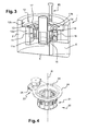
Figure 3 is a partial perspective and section view of the apparatus ofFigure 2 ; -
Figure 4 is a perspective view of the handling system of the apparatus ofFigures 2 and3 ; -
Figure 5 is an exploded view of the handling system ofFigure 4 ; -
Figure 6 is a bottom view of the handling system ofFigure 4 ; -
Figures 7A-C are partial bottom views of the locking system of the handling system ofFigures 4-6 ; -
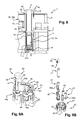
Figure 8 is a partial section view of the apparatus ofFigure 3 with the pull-out system located within the enclosed compartment; -
Figures 9A and 9B are respectively a partial perspective view and a partial exploded view of the handling system and the pull-out system of the apparatus ofFigure 3 ; -
Figure 10 is a side view of the removal member of the pull-out system ofFigures 9A and 9B ; -
Figure 11 is a partial side view of the removal member ofFigure 10 engaged with a holder of a drug container; -
Figure 12 is a partial side view of the removal member and holder ofFigure 11 together with a shaking system; -
Figures 13 and 14 are side views illustrating the inspection step, respectively when the drug container is removed from the enclosed chamber, and when the drug container is removed from the apparatus; -
Figure 15 is a perspective view of a drug administering device to be filled with a dose of the drug of the drug containers of the apparatus ofFigure 3 ; -
Figure 16 is a perspective view of the apparatus ofFigure 1 with side door open showing the docking compartment. - For purposes of the description hereinafter, the terms "upper", "lower", "right", "left", "vertical", "horizontal", "top", "bottom", "lateral", "longitudinal", and derivatives thereof shall relate to the invention as it is oriented in the drawing figures.
- With reference to
Figures 1-3 ,8 and16 , anapparatus 1 is shown in accordance with an embodiment of the invention for storing, transporting and operating treatments or tasks on a plurality of drug containers, such asmultidose vials 10, filled with a drug solution such as vaccine, while maintaining the appropriate temperature and hygienic conditions for preserving the integrity and efficiency of the drug solution. With reference toFigure 8 , avial 10 comprises a tubular barrel having a longitudinal axis, closed at an end and having acollar 3 at the opposite end, saidcollar 3 forming an opening closed by aseptum 4. Theseptum 4 is usually made of a material impermeable to gas and liquid and it seals hermetically the content of thevial 10. Theseptum 4 has an outer surface which is exposed to the outside and which can be pierced by the needle of a drug administering device to withdraw a dose of drug from thevial 10, as will be shown later with reference toFigures 15 and 16 . - In the illustrated embodiment of the invention, the
apparatus 1 comprises a substantiallycylindrical housing 2 closed at its bottom with a transversal wall 5 (seeFigure 16 ) and at its top by atop lid 6. However, alternative external geometries can be appropriate depending on storage and transportation requirements. - With reference to
Figure 2 , which shows theapparatus 1 with thetop lid 6 removed for clarity, theapparatus 1 further comprises anenclosed chamber 11 located in the center of thecylindrical housing 2, thisenclosed chamber 11 receiving a plurality, ten on the example shown, ofvials 10. With further reference toFigure 3 , theapparatus 1 further comprises anenclosed compartment 12 located adjacent to theenclosed chamber 11, and comprising a cylindrical part 12a and atop part 12b. - The cylindrical part 12a of the
enclosed compartment 12 surrounds theenclosed chamber 11 and receives a plurality, five on the example shown inFigure 2 , ofcold storage accumulators 13. Thecold storage accumulators 13 can contain an eutectic fluid which can be frozen in a refrigerating equipment such as a refrigerator and then releases cooling energy to its surrounding environment. Thecold storage accumulators 13 are intended to maintain at least theenclosed chamber 11 at a predetermined temperature range. In the case of vaccines, this temperature range should be between 2°C and 8°C for preserving the integrity and efficiency of the vaccines contained in thevials 10. - The
top part 12b of theenclosed compartment 12, located above theenclosed chamber 11, receives a pull-outsystem 40 for removingvials 10 from theenclosed chamber 11 and from theapparatus 1. The pull-outsystem 40 is actionable by a user and will be described in detail later on. The pull-outsystem 40 also serves for repositioning avial 10 inside theenclosed chamber 11, once inspection and/or other necessary treatments have been performed on thevial 10 previously removed. Thetop part 12b of theenclosed compartment 12 may also receive additionalcold storage accumulators 13, as shown inFigure 8 . - With reference to
Figure 16 , theapparatus 1 further comprises adocking compartment 8, located underneath theenclosed chamber 11, where a drug administering device such as a syringe 9 (seeFigure 15 ) can be secured and can be connected to a selectedvial 10 of theenclosed chamber 11 to withdraw a dose of drug solution, as will be described below. Thecylindrical housing 2 is therefore provided with aside door 7 opening onto thedocking compartment 8. - The walls of the
housing 2 can be suitably made of an insulating material such as, for example, a sandwich of different layers having a hard and smooth surface on the outside for durability and hygiene and internal layer(s) of for example polystyrene foam for insulation purpose. In the illustrated embodiment, thetop lid 6 is snap-fitted onto thecylindrical housing 2, and theside door 7 is hinged onto thecylindrical housing 2. Other securing arrangement of thetop lid 6 andside door 7 onto thehousing 2 can be contemplated. Theside door 7 is also suitably equipped with locking devices to make sure that it cannot be unintentionally opened. - With reference to
Figure 3 , theenclosed chamber 11 will now be described in details. Theenclosed chamber 11 has globally the shape of a cylindrical cavity provided with abottom wall 11a and atop wall 11b. It is thermally sealed except for two apertures, afirst aperture 14 provided in thetop wall 11b, and asecond aperture 15 provided in thebottom wall 11a and facing thefirst aperture 14. The part of theenclosed chamber 11 located between thefirst aperture 14 and thesecond aperture 15 defines a workingarea 16 of theenclosed chamber 11, whereas the rest of theenclosed chamber 11 defines astorage area 17 of theenclosed chamber 11. - As will be clear from the description below, the
storage area 17 is intended to receive the plurality ofvials 10 for storage and transportation, whereas the workingarea 16 is intended to receive onevial 10 at a time, hereinafter referred to as the selectedvial 10a, for submission to various treatments such as inspection, shaking, withdrawal of a dose of drug solution contained therein. In this view, thefirst aperture 14 is dimensioned and shaped so as to allow access to, and removal of, the selectedvial 10a located in said workingarea 16, by the pull-outsystem 40. Thesecond aperture 15 is dimensioned and shaped so as to allow access to theseptum 4 of the selectedvial 10a by theneedle 9a of adrug administering device 9, as shown inFigures 15 and 16 . In case thedocking compartment 8 comprises a top wall adjacent thebottom wall 11a of theenclosed chamber 11, the top wall of the docking compartment may be provided with an opening in communication with thesecond aperture 15 for allowing the needle of thedrug administering device 9 to enter theseptum 4 of the selectedvial 10a. In embodiments not shown, a connector may be provided on thecollar 3 of eachvial 10 in order to limit the contamination of theseptum 4 as several drug administeringdevice needles 9a will pierce successively theseptum 4. - Closure means, such as doors or hatches, may be provided for temporary closing the first and second apertures (14, 15) in view of optimizing the refrigeration and the hygienic conditions of the
enclosed chamber 11 when no treatment is performed on the selectedvial 10a or when no selected vial is present in the workingarea 16 of theenclosed chamber 11. For example, closure means of thesecond aperture 15 may be opened for drug solution withdrawal while closure means of thefirst aperture 14 are closed to maintain the cooling capacity of thecold storage accumulators 13. On the contrary, when the inspection and/or shaking steps are performed on the selectedvial 10a, the closure means of the second aperture may be closed to maintain the cooling capacity of thecold storage accumulators 13 and to avoid contamination from outside air or dust. The closure means are preferably made of an insulating material so as to maintain thevials 10 in an insulated environment. - The
apparatus 1 has thus anenclosed chamber 11 wherevials 10 can be stored in favorable hygienic conditions under a passively maintained temperature. - The
enclosed chamber 11 further comprises a handling system for moving the selectedvial 10a from thestorage area 16 to the workingarea 17 and vice versa. In the illustrated embodiment, the handling system comprises acarrousel 20 capable of rotating around its rotational axis R by means of agear 23 actionable by a user. With reference toFigures 4 and5 , thecarrousel 20 comprises acylindrical basket 21 closed at its bottom by atransversal wall 21b and comprising a plurality of circumferentially distributed lodgings having the shape ofnests 22, eachnest 22 being capable of receiving avial 10, with theseptum 4 andcollar 3 of thevial 10 facing thetransversal wall 21b. Thegear 23 comprises aring 24, intended to be fixed with respect to theapparatus 1, thisring 24 receiving afirst wheel 25 provided withouter teeth 25a capable of cooperating with theouter teeth 26a of asecond wheel 26. Thesecond wheel 26 is coupled to thecylindrical basket 21 via apeg 26b engaging arecess 21a of thecylindrical basket 21. Thefirst wheel 25 is further coupled to abutton 27 capable of being rotated, a part 27a of which protrudes outside the housing 2 (seeFigure 1 ) and is accessible by the user. - When the user rotates the
button 27, thefirst wheel 25 rotates and thereby causes the rotation of thesecond wheel 26 and of thecarrousel 20. Rotation of thecarrousel 20 causes circular movement of thecylindrical basket 21 and therefore of all thenests 22. One of the nests, receiving the selectedvial 10a, is brought to the workingarea 16 of theenclosed chamber 11. Once the selectedvial 10a is in the workingarea 16, it is aligned on a longitudinal axis A joiningfirst aperture 14 tosecond aperture 15, this longitudinal axis being also the longitudinal axis of the pull-out system as will be shown later (seeFigure 8 ). In this position, the outer surface of theseptum 4 of the selectedvial 10 faces thesecond aperture 15 of the workingarea 16. - In the illustrated embodiment, the
apparatus 1 further comprises a locking system for temporary locking operation of the handling system, in particular for temporary locking activation of thebutton 27 by the user, in order to maintain thenest 22 receiving the selectedvial 10a in its position in the workingarea 16 for the time required by the user for performing the tasks he wishes to perform on the selectedvial 10a. - With reference to
Figures 6 and 7A-C , the locking system comprises acogwheel 28 located at the center of the outer face of thetransversal wall 21b of thecylindrical basket 21 and asleeve 29, extending radially from thecogwheel 28 and intended to be fixed with respect to the apparatus 1 (not shown). Thesleeve 29 encloses apeg 30 coupled to elastic return means (not shown) capable of moving thepeg 30 inside and out of saidsleeve 29 under the effect of a stress exerted on thepeg 30. - With reference to
Figures 5, 7A and8 , when anest 22, and the corresponding selectedvial 10a, is in position in the workingarea 16 of theenclosed chamber 11, thepeg 30 is engaged in afirst recess 28a (position named 1 inFigure 7A ) of thecogwheel 28 and the elastic return means are for example in abutment against thepeg 30 and in a rest state. Therefore, moving thepeg 30 out ofrecess 28a requires a specific effort from the user on thebutton 27. As long as the user does not exert this specific effort, thenest 22 positioned in the workingarea 16 will not move, as thebasket 21 is blocked in rotation by means of thepeg 30 being engaged in therecess 28a. When the user decides that no more treatment is to be performed on the selectedvial 10a, he rotatesbutton 27 by applying the necessary effort for disengaging thepeg 30 from therecess 28a. During this step, as shown inFigure 7B , thepeg 30 retracts within thesleeve 29 and causes the elastic return means to be compressed. Thebasket 21 rotates until thepeg 30 faces thenext recess 28b and is pushed in engagement therewith (position named 2 inFigure 7C ) by means of the elastic return means coming back to their rest state, as shown inFigure 7C . Anothernest 22, adjacent thefirst nest 22, is now in position in the workingarea 16 of theenclosed chamber 11, and the user may complete new tasks on a new selectedvial 10a present in thisnew nest 22. - With reference to
Figures 9A to 11 , the pull-outsystem 40 will now be described in detail. The pull-outsystem 40 comprises a removal member under the form of anelongated tube 41 intended to engage the selectedvial 10a at time of removal or repositioning of the selectedvial 10a from or inside theenclosed chamber 11. As shown inFigure 10 , he bottom end of theelongated tube 41 is provided with anouter rim 41a in which is designed a surface defining atransversal slit 41b, the function of which will be explained later on. The pull-outsystem 40 further comprises asleeve 42 surrounding theelongated tube 41, and provided with alongitudinal window 42a for allowing a user to see inside thesleeve 42. The top end of thesleeve 42 comprises an inner rim (not visible in the figures). Thesleeve 42 is movable with respect to theelongated tube 41 between a retracted position in which it significantly surrounds theelongated tube 41, as shown inFigure 9A , and an extended position (seeFigures 13 and 14 ), in which the inner rim of its top end is in abutment on theouter rim 41a of theelongated tube 41. The pull-outsystem 40 further comprises acap 43 covering and snap-fitted to the top part of the elongated tube 41 : in the position where the pull-outsystem 40 is not in use and the selectedvial 10a is not removed from theenclosed chamber 11, as shown inFigures 8 and 9A , thecap 43 is coupled to thesleeve 42 by means of alatch 44 so that thesleeve 42 is in its retracted position and surrounds theelongated tube 41. As shown later on, thelatch 44 is releasable by a user to allow thesleeve 42 to reach its extended position. - With reference to
Figures 9A-11 , eachvial 10 is fixedly received in aholder 45. Theholder 45 allows a simplified handling of thevial 10 and provides protection to the vial, for example against shocks and contamination, during said handling. Theholder 45 has the shape of a sleeve closed at its both ends and receiving thevial 10. Theholder 45 may be made of an insulated material for protecting thevial 10 from heat. In particular, thevial 10 is blocked in longitudinal translation with respect to theholder 45 once it is received therein. Theholder 45 is provided with aside window 45a for allowing the user to see inside the holder, in particular to see thevial 10 and its contents. The top end of eachholder 45 is provided with a surface defining a projectinghead 46. - The use of the
apparatus 1 will now be explained in detail. -
Vials 10 received in theirholders 45 are inserted into thenests 22 of thecarrousel 20 of theenclosed chamber 11. In eachnest 22, theholder 45 is in abutment against thetransversal wall 21b of thecylindrical basket 21 of thecarrousel 20. Thecold storage accumulators 13 which have been previously stored in a refrigeration system, so that the eutectic fluid is preferably entirely solidified, are inserted into theenclosed compartment 12. Thevials 10 are thus surrounded by a cooling capacity. - As shown in
Figure 8 , the pull-outsystem 40 is stored in thetop part 12b of theenclosed compartment 12. Theenclosed compartment 12 has afirst access port 18 in communication with thefirst aperture 14 and asecond access port 19 in communication with the outside. The bottom end of the pull-outsystem 40 faces thefirst access port 18 and its top end, namely thecap 43, protrudes outside theapparatus 1 via thesecond access port 19. Before any use of theapparatus 1, thecap 43 closes thesecond access port 19 for maintaining theenclosed compartment 12 thermally sealed. For the same reason, thefirst aperture 14 and thefirst access port 18 may be closed for maintaining theenclosed chamber 11 thermally sealed and uncontaminated. - The
top lid 6 is closed and preferably locked to avoid any contact with ambient air, at a potentially much higher temperature and likely to carry some contaminants. The temperature within theenclosed chamber 11 is thus remained between 2 degrees Celsius and 8 degrees Celsius over a period of time, for example 10 to 12 days, and the enclosed chamber remains in favorable hygienic conditions. - In this way, the
apparatus 1 can be carried to any places where there is relatively little or limited electricity supply without damaging the content of thevials 10 as theenclosed chamber 11 is kept at the correct temperature. - Furthermore, the
apparatus 1 allows the delivery of drugs and vaccines to people living in remote area, even if dust and contaminants are present, such as in deserts, equatorial or tropical areas, and where no medical infrastructure is available. - When a user decides to perform an operation on a
vial 10 stored in theapparatus 1, he first causes opening of thefirst aperture 14 and of thefirst access port 18, so that thefirst aperture 14 and thefirst access port 18 are in communication with each other. In particular, thetransversal slit 41b of theelongated tube 41 of the pull-outsystem 40 now protrudes inside the workingarea 16 of theenclosed chamber 11. - The user then decides to select a
vial 10 for performing one of the following operations : inspection of thevial 10, and/or shaking thevial 10, and/or proceeding to the withdrawal of a dose of drug solution from saidvial 10. The user rotates thebutton 27 in order to bring a selectedvial 10a in the workingarea 16 of theenclosed chamber 11. Due to the locking system formed by thepeg 30 and thecogwheel 28, the selectedvial 10a is caused to be maintained in the right position in the workingarea 16, aligned onto the longitudinal axis A of the pull-outsystem 40, as shown inFigure 8 . During circular movement of thenest 22 receiving both the selectedvial 10a and itsholder 45, the projectinghead 46 of theholder 45 has cooperated with, and has engaged, thetransversal slit 41b of theelongated tube 41, as shown inFigure 11 . InFigure 11 , thesleeve 42 of the pull-outsystem 40 is not represented for sake of clarity. As a consequence of the projectinghead 46 being engaged in thetransversal slit 41b, the removal member (elongated tube 41) of the pull-outsystem 40 is now engaged with the selectedvial 10a, as shown inFigure 8 . The engagement of the pull-outsystem 40 with the selectedvial 10a therefore occurs automatically as the user rotates thebutton 27. The user needs not to perform additional step than rotating thebutton 27. No opening of theenclosed chamber 11 is required, as well as no direct contact between the user and the selectedvial 10a. All the storedvials 10a are thereby within a desirable temperature range and free of outside contamination. - For being able to remove the selected
vial 10a from theenclosed chamber 11 in a view of inspecting its contents, the user then releases thelatch 44 of the pull-outsystem 40, and he pulls up theelongated tube 41 by means of thecap 43 which is coupled to theelongated tube 41, as shown inFigure 13 . Thelatch 44 being released, thesleeve 42 is no more maintained in its retracted position with respect to theelongated tube 41. As a consequence, as the user pulls up on thecap 43, theholder 45 and thevial 10a are drawn in the top direction with theelongated tube 41. In a first step, thesleeve 42 remains in theenclosed compartment 12 and extends progressively around theholder 45 and thevial 10a, as shown inFigure 13 , on which the top wall of thelid 6 of theapparatus 1 is schematically represented by a dotline. Thesleeve 42 thereby forms an additional protection for the selectedvial 10a, as it is removed from theenclosed chamber 11. - In order to be able to inspect the selected
vial 10a, the user continues pulling on thecap 43 and the inner rim of thesleeve 42 comes in abutment against theouter rim 41a of the elongated tube. By continuing his movement, the user eventually removes theholder 45 and thevial 10a from theapparatus 1 and is allowed to see thevial 10a and its contents via the windows (45a, 42a) of both theholder 45 and thesleeve 42, as shown by the arrow F inFigure 14 , on which the top wall of thelid 6 of theapparatus 1 is schematically represented by a dotline. Although thevial 10a is now outside the apparatus, it is protected both by theholder 45 and thesleeve 42, which may be both formed of insulated material. As such, the user has the time to inspect the contents of thevial 10a, without fearing that the temperature of thevial 10a rises above the desired range of 2-8°C for a vaccine for example. Moreover, with such holder and sleeve, the user does not need to touch directly the selectedvial 10a, preserving it from contamination by direct contact with unclean hands or non-sterile gloves The user may rotate the selectedvial 10a for a better inspection if necessary. - In another embodiment not shown, the transversal slit of the pull-out
system 40 may be replaced by a metal surface. In such a case, the projecting head 46a of theholder 45 may comprise a magnet, able to cooperate with the metal surface. In such an embodiment, the engagement between theelongated tube 41 and theholder 45 is thus achieved as a result of magnetic forces, the operation of the pull-out system remaining unchanged. - With reference to
Figure 12 , is shown an embodiment where ahelical spring 47 is located in thenest 22 between the bottom end of theholder 45 of thevial 10a and the bottomtransversal wall 21b of thecylindrical basket 21. When the pull-outsystem 40 is engaged with theholder 45 by means of projectinghead 46 being engaged intransversal slit 41b, and thelatch 44 is released, the user may apply a pressure on the pull-outsystem 40 in the direction of thebottom wall 21b of thecylindrical basket 21. Under such a pressure, thehelical spring 47 is compressed. When the user releases his pressure, thehelical spring 47 tends to come back naturally to its rest state. A succession of such pressures and releases by the user therefore causes the shaking of the selectedvial 10a and the mixing of its contents. During this shaking, thevial 10a is globally maintained inside theenclosed chamber 11 and there is therefore no risk that its temperature rises above the desired temperature range, for example 2-8°C for a vaccine. Moreover, the shaking is being made inside theenclosed chamber 11, exposition of the selectedvial 10 to outside contaminants is avoided. - Once a selected
vial 10a has been inspected, shaken if necessary, and repositioned it in the workingarea 16 by means of the pull-outsystem 40, the user may proceed to the step of withdrawing a dose of drug solution from the selectedvial 10a, with the help of adrug administering device 9 as shown inFigures 15 and 16 . - With reference to
Figure 15 is shown adrug administering device 9, such as a syringe, provided with aneedle 9a. Thedrug administering device 9 may be secured on avertical shaft 51 of aloading system 50 intended to be positioned in thedocking compartment 8 so that theneedle 9a faces the outer surface of theseptum 4 of the selectedvial 10a (seeFigures 8 and16 ). The user then operates anactuator 52 of theloading system 50 in order to push theneedle 9a towards theseptum 4 so that theneedle 9a pierces theseptum 4 and enters inside the selectedvial 10a. The user then causes the stopper (not visible in the figures) of thedrug administering device 9 to move backwards by pushing backwards theactuator 52, in order to fill said device with a dose of drug solution from the selectedvial 10a. He then removes thedrug administering device 9 from theloading system 50 and proceeds to the injection of the dose of the drug solution to the patient. - Once all the doses of vaccine or drug solution contained in a first selected
vial 10a have been withdrawn, or if the user wishes to fill a drug administering device with a drug solution from anothervial 10 located in thestorage area 17, the user further rotates thebutton 27. The circular movement of thecylindrical basket 21 thus causes the disengagement of the projectinghead 46 of theholder 45 from thetransversal slit 41b of theelongated tube 41. While the circular movement of thecylindrical basket 21 continues, theprojection head 46 of theholder 45 of theadjacent nest 22 becomes automatically engaged in thetransversal slit 41b of theelongated tube 41 of the pull-outsystem 40. The user may then repeat the tasks described above on the new selectedvial 10a. - Additionally, the
apparatus 1 can be equipped with an electronic terminal which can store data such as the type of drug, the date of administration, the number of doses, the type of population etc. For example, a mechanical vial indicator may be used to indicate to the user whichvial 10 is present in the workingarea 16. This could be realized by coupling thesecond wheel 26 of the handling system with a numbered disk capable of indicating which vial number is selected. In such a case, the number could be seen by the user by a specific window (not shown) present for example in the cylindrical part 12a or in thetop part 12b of theenclosed compartment 12. - The described apparatus thus provides a significant improvement as it is possible to transport temperature sensitive drugs such as vaccines stored in multidose containers in an autonomous way, and to complete various tasks and/or operations on a selected container without fearing that the temperature of the selected container rises dramatically above an undesired temperature limit during these treatment steps. Furthermore, the invention allows for preservation of favorable hygienic conditions around the drug containers as manual handling of the drug containers outside of the apparatus is not required. In other terms, the apparatus according to the invention is specifically adapted for transporting and treating temperature sensitive drugs in area where access to electricity is limited or nonexistent and where hygienic conditions required for immunization or cure of patients cannot be sustained.
- In addition, wastage of unused doses stored in an opened multidose vial is avoided, as the apparatus described allows for isolating the vial from outside dust, air contaminants and contaminated surfaces. This maintains efficacy of the contained drug or vaccine overtime and allows using the global content of a multidose vial overtime.
- In addition, by limiting the contaminants reaching directly the surface of the containers, the apparatus of the invention allows limiting or preventing the propagation of diseases from an immunization site to another.
Claims (15)
- An apparatus (1) for transporting and operating treatments on a plurality of drug containers (10) filled with a drug solution and closed by a septum (4), the apparatus comprising :- an enclosed chamber (11) comprising a storage area (17) for storing said plurality of drug containers and a working area (16) capable of receiving one drug container selected from said plurality of drug containers,- a handling system (20) for moving said selected drug container from the storage area to the working area and vice versa,- said working area comprising a first aperture (14) to allow access to said selected drug container from the outside of said enclosed chamber by a pull-out system (40) capable of removing the selected drug container from the enclosed chamber, and a second aperture (15) to allow access to the septum of said selected drug container by a needle (9a) of a drug administering device (9), and- a cold storage accumulator (13) for maintaining the temperature of at least said enclosed chamber at a predetermined temperature range.
- The apparatus (1) of claim 1, further comprising a locking system (28, 29, 30) for temporary locking operation of the handling system when one selected drug container is positioned in said working area.
- The apparatus (1) of claim 1 or 2, further comprising an enclosed compartment (12) capable of receiving said pull-out system before any selected drug container is positioned in said working area, said compartment being located adjacent said enclosed chamber and being provided with a first access port (18) in communication with said first aperture and with a second access port (19) in communication with the outside, said first and second access ports being configured so as to allow removal of said pull-out system and selected drug container from said apparatus.
- The apparatus (1) of claim 3, wherein at least part of said cold storage accumulator is located within said enclosed compartment.
- Apparatus (1) of claim 3 or 4, further comprising a cap (43) for releasingly closing said second access port from the outside.
- Apparatus (1) of any one of claims 3 to 5, further comprising a first surface (46) located on or coupled to said selected drug container, and a second surface (41b) located on said pull-out system, said first and second surfaces being capable of cooperating for automatically engaging each other when said selected drug container is moved from the storage area to the working area and for automatically disengaging from each other when said selected drug container is moved from the working area to the storage area.
- Apparatus (1) of claim 6, wherein said first surface defining a projecting head (46), said second surface defines a transversal slit (41b) capable of receiving said projecting head with engagement.
- Apparatus (1) of claim 6 or 7, wherein said first surface being a metal surface, said second surface is a magnet capable of magnetizing said first surface.
- Apparatus (1) of any one of claims 6 to 8, wherein each drug container being fixedly received in a holder (45), said first surface (46) is located on said holder.
- Apparatus (1) of any one of claims 6 to 9, wherein said second surface (41b) being provided on a removal member (41) of said pull-out system, said pull-out system further comprises a protecting sleeve (42) coupled to said removal member, said protecting sleeve being capable of moving with respect to said removal member at least when said pull-out system and said selected drug container are engaged together, so as to extend around said selected drug container when said pull-out system removes said selected drug container from said working area of said enclosed chamber.
- Apparatus (1) of claim 10, wherein the protecting sleeve is formed of an insulated material.
- Apparatus (1) of any one of claims 1 to 11, further comprising a shaking mechanism (47) allowing the user to shake the selected drug container within said working area of said enclosed chamber when said selected drug container is engaged with said pull-out system.
- Apparatus (1) of claim 12 wherein said selected drug container being received in abutment against a bottom wall (21b) of a lodging (22) of said handling system when said selected drug container is positioned in said working area, said shaking mechanism comprises an elastic component (47) provided between said selected drug container and said bottom wall.
- Apparatus (1) of any one of claims 1 to 13, further comprising a docking compartment (8) configured for receiving said drug administering device (9) and provided with an opening in communication with said second aperture for allowing the needle (9a) of said drug administering device to enter the septum of the selected drug container positioned in said working area.
- Apparatus (1) of any one of claims 1 to 14, further provided with one or more temporary closure(s) for closing one or several of said first and second apertures and of said first and second access ports and said opening, when no treatment is operated on the drug containers, so as to maintain said enclosed chamber and enclosed compartment thermally sealed.
Priority Applications (1)
| Application Number | Priority Date | Filing Date | Title |
|---|---|---|---|
| EP13163260.6A EP2789328A1 (en) | 2013-04-11 | 2013-04-11 | Apparatus for transporting and treating drug containers |
Applications Claiming Priority (1)
| Application Number | Priority Date | Filing Date | Title |
|---|---|---|---|
| EP13163260.6A EP2789328A1 (en) | 2013-04-11 | 2013-04-11 | Apparatus for transporting and treating drug containers |
Publications (1)
| Publication Number | Publication Date |
|---|---|
| EP2789328A1 true EP2789328A1 (en) | 2014-10-15 |
Family
ID=48139724
Family Applications (1)
| Application Number | Title | Priority Date | Filing Date |
|---|---|---|---|
| EP13163260.6A Withdrawn EP2789328A1 (en) | 2013-04-11 | 2013-04-11 | Apparatus for transporting and treating drug containers |
Country Status (1)
| Country | Link |
|---|---|
| EP (1) | EP2789328A1 (en) |
Cited By (1)
| Publication number | Priority date | Publication date | Assignee | Title |
|---|---|---|---|---|
| GB2577683A (en) * | 2018-09-28 | 2020-04-08 | Ideabatic Ltd | A portable temperature-stable storage device |
Citations (2)
| Publication number | Priority date | Publication date | Assignee | Title |
|---|---|---|---|---|
| EP0922186A1 (en) * | 1996-08-30 | 1999-06-16 | Triple CCC CC | Container for a vial or ampoule |
| EP2514456A1 (en) * | 2011-04-21 | 2012-10-24 | Sanofi-Aventis Deutschland GmbH | Injection pen with linear magazine containing medicated modules |
-
2013
- 2013-04-11 EP EP13163260.6A patent/EP2789328A1/en not_active Withdrawn
Patent Citations (2)
| Publication number | Priority date | Publication date | Assignee | Title |
|---|---|---|---|---|
| EP0922186A1 (en) * | 1996-08-30 | 1999-06-16 | Triple CCC CC | Container for a vial or ampoule |
| EP2514456A1 (en) * | 2011-04-21 | 2012-10-24 | Sanofi-Aventis Deutschland GmbH | Injection pen with linear magazine containing medicated modules |
Cited By (2)
| Publication number | Priority date | Publication date | Assignee | Title |
|---|---|---|---|---|
| GB2577683A (en) * | 2018-09-28 | 2020-04-08 | Ideabatic Ltd | A portable temperature-stable storage device |
| GB2577683B (en) * | 2018-09-28 | 2020-09-23 | Ideabatic Ltd | A portable temperature-stable storage device |
Similar Documents
| Publication | Publication Date | Title |
|---|---|---|
| US10966903B2 (en) | Adaptor for coupling to a medical container | |
| US9713574B2 (en) | Dose counting device for coupling with a medical container | |
| US10751252B2 (en) | Adaptor for coupling with a medical container | |
| US9180070B2 (en) | Adaptor for coupling to a medical container | |
| SG192311A1 (en) | Adaptor with injection device for coupling to a medical container | |
| JP6240317B2 (en) | Assembly comprising an adapter and a blister for coupling to a medical container | |
| EP2922521B1 (en) | Adaptor for multidose medical container | |
| WO2023113842A1 (en) | Closed convenience kits for sterilized medicine preparation | |
| SG193656A1 (en) | Housing and apparatus for storing a medical container | |
| EP2759789A1 (en) | Apparatus for handling drug containers | |
| JP7440299B2 (en) | Medical liquid preparation cassettes, kits containing cassettes |
Legal Events
| Date | Code | Title | Description |
|---|---|---|---|
| PUAI | Public reference made under article 153(3) epc to a published international application that has entered the european phase |
Free format text: ORIGINAL CODE: 0009012 |
|
| 17P | Request for examination filed |
Effective date: 20130411 |
|
| AK | Designated contracting states |
Kind code of ref document: A1 Designated state(s): AL AT BE BG CH CY CZ DE DK EE ES FI FR GB GR HR HU IE IS IT LI LT LU LV MC MK MT NL NO PL PT RO RS SE SI SK SM TR |
|
| AX | Request for extension of the european patent |
Extension state: BA ME |
|
| STAA | Information on the status of an ep patent application or granted ep patent |
Free format text: STATUS: THE APPLICATION IS DEEMED TO BE WITHDRAWN |
|
| 18D | Application deemed to be withdrawn |
Effective date: 20150416 |