EP2789298A1 - Tissue anchor and insertion tool - Google Patents
Tissue anchor and insertion tool Download PDFInfo
- Publication number
- EP2789298A1 EP2789298A1 EP20140174999 EP14174999A EP2789298A1 EP 2789298 A1 EP2789298 A1 EP 2789298A1 EP 20140174999 EP20140174999 EP 20140174999 EP 14174999 A EP14174999 A EP 14174999A EP 2789298 A1 EP2789298 A1 EP 2789298A1
- Authority
- EP
- European Patent Office
- Prior art keywords
- anchor
- suture
- implant
- nub
- tissue
- Prior art date
- Legal status (The legal status is an assumption and is not a legal conclusion. Google has not performed a legal analysis and makes no representation as to the accuracy of the status listed.)
- Withdrawn
Links
Images


Classifications
-
- A—HUMAN NECESSITIES
- A61—MEDICAL OR VETERINARY SCIENCE; HYGIENE
- A61B—DIAGNOSIS; SURGERY; IDENTIFICATION
- A61B17/00—Surgical instruments, devices or methods, e.g. tourniquets
- A61B17/04—Surgical instruments, devices or methods, e.g. tourniquets for suturing wounds; Holders or packages for needles or suture materials
- A61B17/0401—Suture anchors, buttons or pledgets, i.e. means for attaching sutures to bone, cartilage or soft tissue; Instruments for applying or removing suture anchors
-
- A—HUMAN NECESSITIES
- A61—MEDICAL OR VETERINARY SCIENCE; HYGIENE
- A61B—DIAGNOSIS; SURGERY; IDENTIFICATION
- A61B17/00—Surgical instruments, devices or methods, e.g. tourniquets
- A61B17/04—Surgical instruments, devices or methods, e.g. tourniquets for suturing wounds; Holders or packages for needles or suture materials
- A61B17/0487—Suture clamps, clips or locks, e.g. for replacing suture knots; Instruments for applying or removing suture clamps, clips or locks
-
- A—HUMAN NECESSITIES
- A61—MEDICAL OR VETERINARY SCIENCE; HYGIENE
- A61B—DIAGNOSIS; SURGERY; IDENTIFICATION
- A61B17/00—Surgical instruments, devices or methods, e.g. tourniquets
- A61B17/04—Surgical instruments, devices or methods, e.g. tourniquets for suturing wounds; Holders or packages for needles or suture materials
- A61B17/0401—Suture anchors, buttons or pledgets, i.e. means for attaching sutures to bone, cartilage or soft tissue; Instruments for applying or removing suture anchors
- A61B2017/0409—Instruments for applying suture anchors
-
- A—HUMAN NECESSITIES
- A61—MEDICAL OR VETERINARY SCIENCE; HYGIENE
- A61B—DIAGNOSIS; SURGERY; IDENTIFICATION
- A61B17/00—Surgical instruments, devices or methods, e.g. tourniquets
- A61B17/04—Surgical instruments, devices or methods, e.g. tourniquets for suturing wounds; Holders or packages for needles or suture materials
- A61B17/0401—Suture anchors, buttons or pledgets, i.e. means for attaching sutures to bone, cartilage or soft tissue; Instruments for applying or removing suture anchors
- A61B2017/0412—Suture anchors, buttons or pledgets, i.e. means for attaching sutures to bone, cartilage or soft tissue; Instruments for applying or removing suture anchors having anchoring barbs or pins extending outwardly from suture anchor body
-
- A—HUMAN NECESSITIES
- A61—MEDICAL OR VETERINARY SCIENCE; HYGIENE
- A61B—DIAGNOSIS; SURGERY; IDENTIFICATION
- A61B17/00—Surgical instruments, devices or methods, e.g. tourniquets
- A61B17/04—Surgical instruments, devices or methods, e.g. tourniquets for suturing wounds; Holders or packages for needles or suture materials
- A61B17/0401—Suture anchors, buttons or pledgets, i.e. means for attaching sutures to bone, cartilage or soft tissue; Instruments for applying or removing suture anchors
- A61B2017/0414—Suture anchors, buttons or pledgets, i.e. means for attaching sutures to bone, cartilage or soft tissue; Instruments for applying or removing suture anchors having a suture-receiving opening, e.g. lateral opening
-
- A—HUMAN NECESSITIES
- A61—MEDICAL OR VETERINARY SCIENCE; HYGIENE
- A61B—DIAGNOSIS; SURGERY; IDENTIFICATION
- A61B17/00—Surgical instruments, devices or methods, e.g. tourniquets
- A61B17/04—Surgical instruments, devices or methods, e.g. tourniquets for suturing wounds; Holders or packages for needles or suture materials
- A61B17/0401—Suture anchors, buttons or pledgets, i.e. means for attaching sutures to bone, cartilage or soft tissue; Instruments for applying or removing suture anchors
- A61B2017/042—Suture anchors, buttons or pledgets, i.e. means for attaching sutures to bone, cartilage or soft tissue; Instruments for applying or removing suture anchors plastically deformed during insertion
- A61B2017/0422—Suture anchors, buttons or pledgets, i.e. means for attaching sutures to bone, cartilage or soft tissue; Instruments for applying or removing suture anchors plastically deformed during insertion by insertion of a separate member into the body of the anchor
- A61B2017/0424—Suture anchors, buttons or pledgets, i.e. means for attaching sutures to bone, cartilage or soft tissue; Instruments for applying or removing suture anchors plastically deformed during insertion by insertion of a separate member into the body of the anchor the separate member staying in the anchor after placement
-
- A—HUMAN NECESSITIES
- A61—MEDICAL OR VETERINARY SCIENCE; HYGIENE
- A61B—DIAGNOSIS; SURGERY; IDENTIFICATION
- A61B17/00—Surgical instruments, devices or methods, e.g. tourniquets
- A61B17/04—Surgical instruments, devices or methods, e.g. tourniquets for suturing wounds; Holders or packages for needles or suture materials
- A61B17/0401—Suture anchors, buttons or pledgets, i.e. means for attaching sutures to bone, cartilage or soft tissue; Instruments for applying or removing suture anchors
- A61B2017/0427—Suture anchors, buttons or pledgets, i.e. means for attaching sutures to bone, cartilage or soft tissue; Instruments for applying or removing suture anchors having anchoring barbs or pins extending outwardly from the anchor body
-
- A—HUMAN NECESSITIES
- A61—MEDICAL OR VETERINARY SCIENCE; HYGIENE
- A61B—DIAGNOSIS; SURGERY; IDENTIFICATION
- A61B17/00—Surgical instruments, devices or methods, e.g. tourniquets
- A61B17/04—Surgical instruments, devices or methods, e.g. tourniquets for suturing wounds; Holders or packages for needles or suture materials
- A61B17/0401—Suture anchors, buttons or pledgets, i.e. means for attaching sutures to bone, cartilage or soft tissue; Instruments for applying or removing suture anchors
- A61B2017/0438—Suture anchors, buttons or pledgets, i.e. means for attaching sutures to bone, cartilage or soft tissue; Instruments for applying or removing suture anchors slotted, i.e. having a longitudinal slot for enhancing their elasticity
-
- A—HUMAN NECESSITIES
- A61—MEDICAL OR VETERINARY SCIENCE; HYGIENE
- A61B—DIAGNOSIS; SURGERY; IDENTIFICATION
- A61B17/00—Surgical instruments, devices or methods, e.g. tourniquets
- A61B17/04—Surgical instruments, devices or methods, e.g. tourniquets for suturing wounds; Holders or packages for needles or suture materials
- A61B17/0401—Suture anchors, buttons or pledgets, i.e. means for attaching sutures to bone, cartilage or soft tissue; Instruments for applying or removing suture anchors
- A61B2017/044—Suture anchors, buttons or pledgets, i.e. means for attaching sutures to bone, cartilage or soft tissue; Instruments for applying or removing suture anchors with a threaded shaft, e.g. screws
-
- A—HUMAN NECESSITIES
- A61—MEDICAL OR VETERINARY SCIENCE; HYGIENE
- A61B—DIAGNOSIS; SURGERY; IDENTIFICATION
- A61B17/00—Surgical instruments, devices or methods, e.g. tourniquets
- A61B17/04—Surgical instruments, devices or methods, e.g. tourniquets for suturing wounds; Holders or packages for needles or suture materials
- A61B17/0401—Suture anchors, buttons or pledgets, i.e. means for attaching sutures to bone, cartilage or soft tissue; Instruments for applying or removing suture anchors
- A61B2017/0445—Suture anchors, buttons or pledgets, i.e. means for attaching sutures to bone, cartilage or soft tissue; Instruments for applying or removing suture anchors cannulated, e.g. with a longitudinal through-hole for passage of an instrument
-
- A—HUMAN NECESSITIES
- A61—MEDICAL OR VETERINARY SCIENCE; HYGIENE
- A61B—DIAGNOSIS; SURGERY; IDENTIFICATION
- A61B17/00—Surgical instruments, devices or methods, e.g. tourniquets
- A61B17/04—Surgical instruments, devices or methods, e.g. tourniquets for suturing wounds; Holders or packages for needles or suture materials
- A61B17/0401—Suture anchors, buttons or pledgets, i.e. means for attaching sutures to bone, cartilage or soft tissue; Instruments for applying or removing suture anchors
- A61B2017/0446—Means for attaching and blocking the suture in the suture anchor
- A61B2017/0458—Longitudinal through hole, e.g. suture blocked by a distal suture knot
Definitions
- This invention relates to tissue anchors and tools for inserting tissue anchors.
- Soft tissue such as ligaments and tendons, after they have torn away from bone, can be reattached using suture,
- a surgeon inserts an anchor with an attached suture into the bone and ties the suture about the soft tissue to secure the soft tissue to the bone.
- Tools for inserting pound-in type anchors generally include an outer tube in which the anchor is located, and an inner pusher tube for expelling the anchor from the tool.
- Tools for inserting screw-in type anchors generally have a tube that is somehow keyed to the anchor, typically by including a hexagonal-shaped end on the anchor and a hexagonal-shaped opening in the tube for receiving the end of the anchor, such that rotation of the tool acts to screw in the anchor.
- a surgical tool includes a shaft for receiving implants.
- the shaft defines a non-linear track.
- the tool includes, e.g., a deployment member movable along the track to deploy the implants.
- the track includes longitudinal and lateral sections.
- the deployment member includes a nub received in the track.
- the deployment member includes a handle and the nub extends from an inner surface of the handle.
- the deployment member includes a pusher for engaging the implants.
- the shaft defines a lumen for receiving the pusher.
- the track defines a formation for releasably locking the deployment member.
- the formation is a concavity
- the deployment member includes a nub releasably received in the concavity.
- the shaft is a cylindrical member and defines a lumen for receiving the implants.
- the shaft includes an adapter defining the track and a longitudinally extending member for receiving the implants.
- the surgical tool includes a second shaft coupled to the adapter and positioned alongside the longitudinally extending member.
- the surgical tool includes a hole forming member received by the second shaft and a lever coupled to the hole forming member for distally advancing the hole forming member relative to the second shaft.
- the adapter defines a second track for receiving the lever. Alternatively, a nub is received in the first track for advancing the hole forming member relative to the second shaft.
- a surgical tool includes implants and a shaft for receiving the implants.
- the shaft defines a non-linear track.
- the surgical tool includes, e.g., a deployment member movable along the track to selectively deploy the implants.
- Embodiments of this aspect of the invention may include a spacer disposed between two implants.
- a method includes advancing a shaft to a surgical site, the shaft housing implants, and moving a deployment member along a non-linear track defined by the shaft to deploy the implants into tissue at the surgical site.
- an implant includes a body, and a plurality of alternating threads and flutes helically arranged about the body such that the body rotates under a linear applied force.
- Each thread includes, e.g., multiple barbs.
- Embodiments of this aspect of the invention may include that the body defines a longitudinal passage.
- an implant includes a body having a distal end for pound-in advancement into tissue.
- the body includes, e.g., a plurality of cone-shaped, stacked barbs, and a diameter of an outermost region of the barbs increases proximally.
- Embodiments of this aspect of the invention may include a proximal break-away hub.
- a surgical tool includes a first member, a first implant coupled to the first member, a second member coupled to the first member, and a second implant coupled to the second member.
- the first implant has, e.g., forward threads and the second implant has, e.g., reverse threads,
- the surgical tool includes a suture joining the first and second implants.
- the first member defines a lumen and the second member is received within the lumen.
- the surgical tool includes a deployment element for advancing the second member relative to the first member.
- a surgical tool includes a first member, a first implant coupled to the first member, a second member coupled to the first member, and a second implant coupled to the second member.
- the first implant has, e.g., threads for rotary advancement into tissue and the second implant is configured, e.g., for pound-in advancement into tissue,
- the surgical tool includes a suture joining the first and second implants.
- the first member defines a lumen and the second member is received within the lumen.
- the surgical tool includes a deployment element for advancing the second member relative to the first member.
- a surgical tool includes a first member, a first implant coupled to the first member, a second member coupled to the first member, and a second implant coupled to the second member.
- the first and second implants are configured, e.g., for pound-in advancement into tissue.
- the surgical tool includes a suture joining the first and second implants.
- the first member defines a lumen and the second member is received within the lumen.
- the surgical tool includes a deployment element for advancing the second member relative to the first member.
- a surgical tool includes a first member, a first implant coupled to the first member, a second member coupled to the first member, and a second implant coupled to the second member.
- the first implant includes, e.g., means for advancement into tissue
- the second implant includes, e.g., means for advancement into tissue.
- the first implant means for advancement includes forward threads.
- the second implant means for advancement includes reverse threads.
- the first implant means for advancement includes threads for rotary advancement into tissue.
- the second implant means for advancement includes means for pound-in advancement into tissue.
- the first implant means for advancement includes means for pound-in advancement into tissue.
- the surgical tool further includes a suture joining the first and second implants.
- the first member defines a lumen and the second member is received within the lumen.
- the surgical tool also includes a deployment element for advancing the second member relative to the first member.
- an insertion tool 100 permitting arthroscopic insertion of two anchors coupled by a suture to, e.g., attach soft tissue to bone, includes an outer tubular member 110 for housing the two anchors, an adaptor 130 enabling controlled deployment of the anchors from outer tubular member 110, and an actuating handle 120 for deploying the anchors.
- handle 120 has a nub 126 and adaptor 130 defines a guide track 140 that receives nub 126 such that movement of nub 126 along track 140 guides the deployment of the two anchors from outer tubular member 110.
- outer tubular member 110 has a proximal region 113 and a distal region 111.
- Distal region 111 has an anchor receiver 118 for receiving the anchors.
- Adaptor 130 has a distal face 131 defining a through bore 132 for receiving proximal region 113 of outer tubular member 110.
- Outer tubular member 110 has a wall 112 defining a pair of substantially parallel longitudinal slots 114A, 114B extending through wall 112 in distal region 111, for purposes described below.
- handle 120 includes a hand grip 120a and a plunger member 128.
- Hand grip 120a has a distal end 121 with a distal wall 124.
- Wall 124 defines a circular opening 122 into a conical chamber 123 bounded by an interior wall 125.
- Nub 126 extends radially inward from interior wall 125.
- Opening 122 and chamber 123 are dimensioned to receive a proximal end 133 of adaptor 130 such that nub 126 is located in track 140 to attain guided relative motion between handle 120 and adaptor 130.
- Plunger member 128 is received within adapter through bore 132 and within outer tubular member 110.
- Plunger member 128 has a distal region 127 terminating in a contact face 129 for engaging an anchor located within outer tubular member 110,
- guide track 140 extends from proximal end 133 along part of the length of adaptor 130.
- Guide track 140 is formed by a first longitudinal extent 154, a first lateral extent 150, a second longitudinal extent 148, a second lateral extent 144, and a third longitudinal extent 142.
- First longitudinal extent 154 opens at a hole 157 in proximal end 133 to allow nub 126 to enter track 140.
- First longitudinal extent 154 extends distally from hole 157 to a first junction 155 with first lateral extent 150.
- First lateral extent 150 includes a stop 151 that is dimensioned to releasably receive nub 126 to hinder relative movement of nub 126 along track 140.
- Stop 151 is a concave depression in the proximal wall 150P of lateral extent 150 with a radius of curvature slightly larger than the radius of nub 126.
- First lateral extent 150 extends laterally along the outer circumference of adaptor 130 from first junction 155 with first longitudinal extent 154 to a second junction 149 with second longitudinal extent 148.
- Second longitudinal extent 148 extends distally from second junction 149 to a third junction 147 with second lateral extent 144, and has a length of about 1 inch (normalized with respect to a received suture anchor).
- Second lateral extent 144 includes a stop 145 that is similar to stop 151, and extends laterally along the outer circumference of adaptor 130 from third junction 147 to a fourth junction 143 with third longitudinal extent 142.
- Third longitudinal extent 142 extends distally from fourth junction 143 to an end 141, and has a length of about 1 inch (normalized with respect to a received suture anchor). The lengths of second longitudinal extent 148 and third longitudinal extent 142 determine the insertion depth of the two anchors housed in member 110, as discussed further below.
- anchor receiver 118 of outer tubular member 110 receives two anchors 80, 90, e.g., pound-in anchors, arranged in a row.
- Anchors 80, 90 each include a distal end 81, 91 capped by a tip 82, 92 and a proximal end 83, 93 with a suture eyelet 84, 94 ( FIG. 4 ), respectively. Tips 82, 92 are sufficiently robust to penetrate tissue, e.g., bone, Eyelets 84, 94 are dimensioned to pass at least one strand of suture for connecting the suture to anchors 80, 90, as discussed below in regard to FIG. 17 .
- Anchors 80, 90 are lined by a series of barb threads 85, 95 for retaining anchor 80, 90 in the penetrated tissue, as discussed below in regard to FIGS. 14A-16 .
- Anchors 80, 90 are separated by a spacer 60 that is also inside outer tubular member 110.
- Spacer 60 has a distal end 61 with a contact face 62 and a proximal end 63 that defines a tip dock 64.
- contact face 62 abuts proximal end 83 of anchor 80, and tip dock 64 receives tip 92 of anchor 90.
- Tip dock 64 is generally conical in shape to increase the contact area with tip 92 and prevent tip 92 from penetrating tip dock 64.
- Anchors 80, 90 and spacer 60 thus form a mechanical linkage capable of transmitting an expulsion force from anchor 90 to anchor 80 to insert anchor 80 into tissue, e.g., bone.
- an anchor assembly 40 is formed by anchors 80, 90 and spacer 60 joined by a suture 50.
- Suture 50 is retained in anchor receiver 118 inside outer tubular member 110 along with anchors 80, 90 and spacer 60.
- Suture 50 has a first knotted loop 51 that passes through eyelet 94 for joining suture 50 to anchor 90, and a first suture portion 52 that extends from eyelet 94 through eyelet 84.
- Suture 50 has a second portion 53 that exits eyelet 84 and is tied in a slip knot 54 with first suture portion 52.
- Suture 50 also includes a third suture portion 56 that exits slip knot 54 and extends to an end 57 joined to spacer 60.
- suture runs along either side of anchor 90 with slip knot 54 positioned proximal of anchor 90.
- slip knot 54 is a one-way knot in that the slip knot permits shortening of suture portion 52, but limits any tendency of suture portion 52 to lengthen.
- an operator positions insertion tool 100 with anchor receiver 118 oriented toward a selected surgical site 31 in a bone 30.
- Surgical site 31 is, e.g., a site where a soft tissue 34 is to be reattached to bone 30.
- Insertion tool 100 is preloaded with anchors 80, 90, spacer 60, and suture 50 with slip knot 54.
- nub 126 has been advanced through hole 157 along first longitudinal extent 154 and a portion of first lateral extent 150 of track 140 to stop 151 ( FIG. 2B ).
- the operator then advances anchor receiver 118 to contact surgical site 31 and presses handle 120 distally to release nub 126 from stop 151.
- the operator rotates handle 120 in the direction of arrow R1 to move nub 126 further along first lateral extent 150 to junction 149, where nub 126 enters longitudinal extent 148.
- the operator then applies an axial force F1 to handle 120, moving nub 126 distally along second longitudinal extent 148 and advancing plunger member 128 such that contact face 129 of plunger member 128 engages proximal end 93 of anchor 90 pushing anchor 90 distally.
- Tip 92 of anchor 90 in turn presses against tip dock 64 of spacer 60 which in turn presses against proximal end 83 of anchor 80 to push anchor 80 distally out of tubular member 110, causing tip 82 of anchor 80 to penetrate into bone 30 at site 31.
- nub 126 When nub 126 reaches the end of second longitudinal extent 148 at junction 147, the penetration of anchor 80 into bone 30 is completed. The operator then rotates handle 120 in the direction of arrow R2, moving nub 126 along a portion of second lateral extent 144 of track 140 to stop 145. The operator then releases the distally-directed pressure on handle 120 so that stop 145 receives nub 126 to hinder further relative movement between handle 120 and adaptor 130.
- the operator applies a force F2 to handle 120 moving nub 126 distally along third longitudinal extent 142 such that contact face 129 of plunger member 128 pushes against proximal end 93 of anchor 90 pushing anchor tip 92 into bone 30 at site 32.
- Penetration proceeds until nub 126 reaches end 141, at which time anchor assembly 40 is fully deployed from insertion tool 100.
- the operator then removes insertion tool 100 from surgical site 32, pulls on spacer 60 to shorten suture portion 62 and thus hold soft tissue 34 to bone 30.
- Slip knot 54 acts to limit loosening of the suture.
- adaptor 330 defines a first guide track 340 and a second guide track 360.
- Guide track 340 guides the deployment of the two anchors from member 310 in the same manner as described above with reference to guide track 140.
- Guide track 360 guides the extension and retraction of awl 390 by lever 337.
- Lever 337 is coupled to awl 390, e.g., by a press fit, welding or soldering.
- Outer tubular member 310 has a proximal end 313 and a distal end 311 with an anchor receiver 318 for receiving the suture anchors.
- Tubular member 310 has a wall 312 with a pair of substantially parallel longitudinal slots 314A, 314B extending therethrough at distal end 311.
- anchor receiver 318 of member 310 receives anchors 80, 90 in the same manner as described above with reference to anchor receiver 118.
- Member 315 has a wall 316 defining a lumen 316a for receiving retractable awl 390.
- Member 315 has a proximal end 317 and a distal end 319.
- Distal end 317 has an inner radial lip 382 defining a hole 380.
- Awl 390 has an extensible portion 394 dimensioned to pass through hole 380, and a body portion 396.
- Extensible portion 394 ends in an awl tip 391.
- Body portion 396 is dimensioned to catch on inner radial lip 382 such that body portion 396 cannot extend through hole 380.
- Member 315 also includes a compression spring 384 that acts between a distal end 395 of body portion 396 and radial lip 382 to retract extensible portion 394 into lumen 316a when lever 337 is moved proximally, as discussed further below.
- handle 320 includes a hand grip 320a and a plunger member 328.
- Hand grip 320a has a distal end 321 with a distal wall 324.
- Wall 324 defines a circular opening 322 into a conical chamber 323 bounded by an interior wall 325.
- Nub 326 extends radially inward from interior wall 325. Opening 322 and chamber 323 are dimensioned to receive proximal end 333 of adaptor 330 and maintain nub 326 in track 340 to attain guided relative motion between handle 320 and adaptor 330 for deploying two anchors from member 310.
- Distal end 321 also defines a longitudinal slit 328a that extends proximally from a distal opening 327a at wall 324.
- Longitudinal slit 328a is angularly positioned relative to nub 326 such that, when nub 326 is received in longitudinal extent 342 of adapter 330, slit 328 is radially aligned with second guide track 360.
- Plunger member 328 is dimensioned to slidably fit within member 310.
- Plunger member 328 has a distal region 327 terminating in a contact face 329 for engaging an anchor located within outer tubular member 310.
- adaptor 330 has a proximal end 333 and a distal face 331 defining a pair of through bores 332, 334.
- Plunger member 128 is received within adapter through bore 332.
- Proximal end 313 of tubular member 310 is received within through bore 332, and a proximal end 317 of tubular member 315 is received within through bore 334.
- Guide tracks 340, 360 extend along opposite sides of adaptor 330.
- Guide track 340 is formed by a first longitudinal extent 354, a first lateral extent 350, a second longitudinal extent 348, a second lateral extent 344, and a third longitudinal extent 342.
- First longitudinal extent 354 opens at a hole 357 in proximal end 333 to allow nub 326 to enter track 340.
- First longitudinal extent 354 extends distally from hole 357 to a first junction 355 with first lateral extent 350.
- First lateral extent 350 includes a stop 351 that is dimensioned to releasably receive nub 326 to hinder relative movement of nub 326 along track 340.
- Stop 351 is a concave depression in the proximal wall 350P of lateral extent 350 with a radius of curvature slightly larger than the radius of nub 326.
- First lateral extent 350 extends laterally along the outer circumference of adaptor 330 from first junction 355 with first longitudinal extent 354 to a second junction 349 with second longitudinal extent 348.
- Second longitudinal extent 348 extends distally from second junction 349 to a third junction 347 with second lateral extent 344, and has a length of about 1 inch (normalized with respect to a received suture anchor).
- Second lateral extent 344 includes a stop 345 that is similar to stop 351, and extends laterally along the outer circumference of adaptor 330 from third junction 347 to a fourth junction 343 with third longitudinal extent 342.
- Third longitudinal extent 342 extends distally from fourth junction 343 to an end 341, and has a length of about 1 inch (normalized with respect to a received suture anchor). The lengths of second longitudinal extent 348 and third longitudinal extent 342 determine the insertion depth of the two anchors housed in member 310, as discussed further below.
- Guide track 360 is formed by a longitudinal extent 362 and a lateral extent 364.
- Longitudinal extent 362 extends distally from a proximal side 361 to a junction 363 with lateral extent 364.
- Lateral extent 364 extends laterally along the outer circumference of adaptor 330 from junction 363 to a stop 365.
- Stop 365 is dimensioned to releasably receive lever 337 to hinder relative movement of lever 337 along track 360 and maintain extensible portion 394 of awl 390 extended through hole 380.
- Stop 363 is a concave depression in the proximal wall 364P of lateral extent 364 with a radius of curvature slightly larger than the radius of lever 337 in track 360.
- an operator positions insertion tool 300 with members 310, 315 oriented toward a selected surgical site 31 in a bone 30.
- Surgical site 31 is, e.g., a site where a soft tissue 34 is to be reattached to bone 30.
- Insertion tool 300 is preloaded with anchors 80, 90, spacer 60, and suture 50 with a slip knot.
- Nub 326 has been advanced through hole 357 along first longitudinal extent 354 and a portion of first lateral extent 350 of track 340 to stop 351 of FIG. 6C .
- Awl lever 337 is positioned proximally in track 360 such that the awl is retracted.
- the operator advances lever 337 distally along longitudinal extent 362 of track 360, advancing the awl out of member 315.
- lever 337 reaches junction 363
- the operator moves lever 337 laterally along lateral portion 364 into stop 365 which receives lever 337 and maintains the awl in the extended position.
- the operator uses the awl to make a hole 31H through the soft tissue into bone 30 at surgical site 31.
- lever 337 moves lever 337 laterally along lateral portion 364 out of stop 365 toward junction 363.
- the operator releases lever 337 and spring 384 ( FIG. 7 ) pushes lever 337 proximally to retract extensible portion 394 of the awl into member 315.
- the operator then aligns anchor receiver 318 with hole 31H and presses handle 320 distally to release nub 326 from stop 351.
- the operator rotates handle 320 in the direction of arrow R1 to move nub 326 further along first lateral extent 350 to junction 349, where nub 326 enters longitudinal extent 348.
- the operator applies a force F1 to handle 320, moving nub 326 distally along second longitudinal extent 348 and advancing contact face 329 of plunger member 328 (shown in FIG. 6B ) against proximal end 93 of anchor 90 to deploy anchor 80 as described above.
- the operator then rotates handle 320 in the direction of arrow R2, moving nub 326 along a portion of second lateral extent 344 of track 340 to stop 345 (shown in FIG. 6C ).
- the operator then releases the distally-directed pressure on handle 320 so that stop 345 receives nub 326 to hinder further relative movement between handle 320 and adaptor 330.
- Lever 337 has been moved distally in track 360 by the action of handle 320, though the awl is still fully located within member 315.
- the operator then withdraws tool 300 from hole 31H, drawing suture 50 through one of slots 314A, 314B and spacer 60 out of anchor receiver 318.
- the operator then orients members 310, 315 toward a second selected surgical site 32.
- lever 337 advances lever 337 distally along longitudinal extent 362 of track 360, advancing the awl out of member 315.
- lever 337 moves lever 337 laterally along lateral portion 364 into stop 365 which receives lever 337 and maintains the awl in the extended position.
- the operator uses the awl to make a hole 32H through the soft tissue into bone 30 at surgical site 32.
- lever 337 moves lever 337 laterally along lateral portion 364 out of stop 365 toward junction 363.
- the operator releases lever 337 and spring 384 ( FIG. 7 ) pushes lever 337 proximally to retract extensible portion 394 of the awl into member 315.
- the operator then aligns anchor receiver 318 with hole 32H and presses handle 320 distally to release nub 326 from stop 345.
- the operator rotates handle 320 in the direction of arrow R3 to move nub 326 further along second lateral extent 344 to junction 343, where nub 326 enters third longitudinal extent 342.
- the operator applies a force F2 to handle 320, moving nub 326 distally along third longitudinal extent 342 and advancing contact face 329 against proximal end 93 of anchor 90 to deploy anchor 90, as described above.
- lever 337 enters track 342 of handle 320.
- the operator then moves insertion tool 300 away from hole 32H, and grasps spacer 60 to tighten suture portion 62 and hold a soft tissue 34 to bone 30.
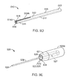
- FIG. 9A another suture anchor insertion tool 500 permits arthroscopic insertion of two anchors coupled by a suture to, e.g., attach soft tissue to bone.
- Insertion tool 500 includes an outer tubular member 510 that receives the two anchors and a retractable awl 590.
- Awl 590 has a tip 591 for forming a hole in bone.
- Tool 500 includes an actuating handle 520 for deploying the anchors and extending awl 590, and an adaptor 530 having a guide track 560 enabling controlled deployment of the anchors and awl 590 from member 510.
- member 510 has a proximal end 513 and a distal end 511 with an anchor receiver 518 for receiving the suture anchor.
- Member 510 has an outer circumferential wall 512 and an inner wall 516 that divides the interior of member 510 into a plunger channel 515 and an awl channel 517.
- Anchor receiver 518 is part of plunger channel 515.
- Wall 512 defines a pair of substantially parallel longitudinal slots 514A, 514B that extend into anchor receiver 518.
- Anchor receiver 518 receives anchors 80, 90 as described above.
- Awl 590 is spring loaded as shown in FIG. 7 .
- handle 520 includes a hand grip 520a and a plunger member 528.
- Handle 520 has a distal end 521 bounded by a distal wall 524.
- Wall 524 defines a circular opening 522 into a conical chamber 523 bounded by an interior wall 525. Opening 522 and chamber 523 are dimensioned to receive proximal end 533 of adaptor 530 to attain guided relative motion between handle 520 and adaptor 530.
- a pair of nubs 526, 527 extend radially inward from interior wall 525. Nubs 526, 527 are relatively positioned to be received by track 560 to enable controlled deployment of the anchors and awl 590 from member 510.
- Plunger member 528 is dimensioned to slidably fit within plunger channel 515 of member 510. Plunger member 528 terminates in a contact face 529.
- adaptor 530 defines a single guide track 560 that guides the deployment of two anchors and extension and retraction of awl 590 from member 510.
- Adaptor 530 has a proximal end 533 and a distal face 531 and defines a through bore hole 532 that receives proximal end 513 of tubular member 510 and plunger 528.
- Guide tracks 560 wraps around the outer circumference of adaptor 530.
- Guide track 540 is formed by a first longitudinal extent 582, a first lateral extent 578, a second longitudinal extent 576, a second lateral extent 372, a third longitudinal extent 568, a third lateral extent 564, and a fourth longitudinal extent 562.
- First longitudinal extent 582 opens at a hole 583 in proximal end 533 to allow nubs 926, 927 to enter track 560, as discussed further below.
- First longitudinal extent 354 extends distally from hole 583 to a first junction 581 with first lateral extent 578.
- First lateral extent 578 includes a stop 579 that is dimensioned to releasably receive nubs 926, 927 to hinder relative movement of nubs 926, 927 along track 560.
- Stop 579 is a concave depression with a radius of curvature slightly larger than the radius of nub 326.
- First lateral extent 578 extends laterally along the outer circumference of adaptor 530 from first junction 581 with first longitudinal extent 582 to a second junction 577 with second longitudinal extent 576, Second longitudinal extent 576 extends distally from second junction 577 to a third junction 575 with second lateral extent 572.
- Second longitudinal extent 576 has a length of about 1 inch (normalized with respect to a received suture anchor).
- Second lateral extent 572 includes a stop 573 that is similar to stop 579.
- Second lateral extent 572 extends laterally along the outer circumference of adaptor 530 from third junction 575 to a fourth junction 569 with third longitudinal extent 568.
- Third longitudinal extent 568 extends distally from fourth junction 569 to a fifth junction 567 with third lateral extent 564.
- Third longitudinal extent 568 has a length of about 1 inch (normalized with respect to a received suture anchor).
- Third lateral extent 564 includes a stop 565 that is similar to stop 579.
- Third lateral extent 564 extends laterally along the outer circumference of adaptor 530 from fifth junction 567 to a sixth junction 563 with fourth longitudinal extent 562.
- Fourth longitudinal extent 562 extends distally from sixth junction 563 to an end 561, and has a length of about 1 inch (normalized with respect to a received suture anchor).
- an operator positions insertion tool 500 with awl 590 oriented toward a selected surgical site 31 in a bone 30.
- Surgical site 31 is, e.g., a site where a soft tissue 34 is to be reattached to bone 30.
- Insertion tool 500 is preloaded with anchors 80, 90, spacer 60, and suture 50 with a slip knot.
- Nub 526 has been advanced through hole 583 along first longitudinal extent 582 and a portion of first lateral extent 578 of track 560 to stop 579 of FIG. 9B .
- Nub 526 contacts a proximal end 593 of awl 590 to extend and maintain awl 590 out of awl channel 517.
- the operator uses awl 590 to form a hole 31H in bone 30 and soft tissue 36.
- the operator rotates handle 520 in the direction of arrow R10 to move nub 526 out of stop 579 and into longitudinal extent 576. This moves nub 526 out of contact with a proximal end 593 of awl 590 to allow a spring (not shown) to retract awl 590 into awl channel 517, as described above.
- the operator then positions anchor receiver 518 at hole 31H in preparation for insertion of anchor 90.
- the operator applies a force F10 to handle 520 moving nub 526 distally along longitudinal extent 576 and advancing plunger member 528 to deploy anchor 80.
- the operator then rotates handle 520 in the direction of arrow R11, moving nub 526 along a portion of second lateral extent 572 of track 560 to stop 573 (shown in FIGS. 9B and 9C ).
- the operator then releases the distally-directed pressure on handle 520 so that stop 573 receives nub 526 to hinder further relative movement between handle 520 and adaptor 530.
- the operator then withdraws tool 500 from hole 31H, drawing suture 50 through one of slots 514A, 514B.
- the operator then rotates handle 520 in the direction of arrow R12 to move nub 526 out of stop 573 and to junction 569 of lateral extent 572 and longitudinal extent 568.
- the rotation of handle 520 in the direction of arrow R12 also brings nub 527 into contact with the distal end 593 of awl 590.
- the operator then pushes distally on handle 520 to advance nub 526 distally along longitudinal extent 568 and to advance nub 527 into longitudinal extent 582.
- the advancement of nub 526 along longitudinal extent 568 pushes spacer 60 out of anchor receiver 518.
- nub 527 into longitudinal extent 582 extends awl 590 out of awl channel 515.
- the operator rotates handle 520 in the direction of arrow R13 to move nub 527 into stop 565 in lateral extent 564 and nub 526 into stop 579 in lateral extent 578.
- the operator then uses awl 590 to form a hole 32H in the bone at surgical site 32.
- the operator rotates handle 520 in the direction of arrow R14. This rotation moves nub 527 out of stop 579 and into longitudinal extent 576, and moves nub 526 out of stop 565 and into longitudinal extent 562. This moves nub 526 out of contact with a proximal end 593 of awl 590 to allow the spring to retract awl 590 into awl channel 517.
- the operator positions anchor receiver 518 at hole 31H in preparation for insertion of anchor 90.
- the operator applies a force F12 to handle 520 moving nub 526 distally along longitudinal extent 562 and nub 527 distally along longitudinal extent 576, and advancing plunger member 528 to deploy anchor 90.
- the operator then moves insertion tool 500 away from hole 32H, and grasps spacer 60 to tighten suture portion 62 and hold a soft tissue 34 to bone 30.
- Insertion tool 800 permits arthroscopic insertion of two anchors coupled by a suture to, e.g., attach soft tissue to bone.
- Insertion tool 800 includes a handle 810, an outer tubular member 820 for housing the two anchors, and a plunger member 830 for inserting one of the two anchors, as discussed below.
- Handle 810 has a distal end 811 and a proximal end 813 and defines an interior channel 814 extending therebetween that receives plunger member 830.
- Distal end 811 of handle 810 defines a cutout portion 812 for receiving a proximal end 823 of member 820 in, e.g., a compression fit.
- Member 820 has a distal end 821 and proximal end 823, and has a wall 827 defining an axial channel 824 extending from proximal end 823 to distal end 821.
- axial channel 824 of member 820 communicates with interior channel 814 of handle 810 to form a passage for plunger member 830.
- Distal end 821 of member 820 includes a suture anchor receiver 828 for non-rotatably mating with a first suture anchor 880.
- Channel 824 is, e.g., hex-shaped in the region of anchor receiver 828, and anchor 880 includes a mating portion 882 that is, e.g., a male hex head to couple suture anchor 880 to suture anchor receiver 828 for combined rotation.
- Anchor 880 is held in the channel by, e.g., a friction fit or an interference fit.
- Suture anchor 880 also includes a thread 884 for facilitating torsional insertion of suture anchor 880 into bone.
- Plunger member 830 includes an elongate rod portion 834 with a distal end 831 defining a contact face 832 and a proximal end 833 terminating in a knob 836.
- Rod portion 834 is dimensioned to slide within axial channel 824 of member 820 and axial channel 814 of handle 810.
- a second suture anchor 890 is received in axial channel 824 of member 820 and is dimensioned to slide therein.
- Suture anchor 890 is designed for pound-in insertion into bone as discussed in, e.g., FIGS. 14A-16B .
- Suture anchors 880, 890 are, e.g., joined by a suture with a slip knot and separated by a spacer as illustrated in FIG. 4 .
- an operator inserts suture anchor 880 into a first surgical site by contacting suture anchor 880 to the site and applying a rotational torque R15 to handle 810. The operator then contacts suture anchor 890 to a second surgical site and applies an axial force F15 to knob 836 to drive plunger member 830 distally and deploy suture anchor 890 distally out of channel 824 and into the second surgical site.
- Insertion tool 900 permits arthroscopic insertion of two anchors coupled by a suture to, e.g., attach soft tissue to bone.
- Insertion tool 900 includes a handle 910 defining a guide slot 940, an outer tubular member 920 having a first anchor receiver 921 for receiving the first suture anchor 980, and a plunger member 930 having a second anchor receiver 931 for receiving the second suture anchor 990.
- Plunger member 930 is slidably received inside member 920 and is guided by guide slot 940 for inserting second suture anchor 990 into bone.
- Handle 910 has a distal end 911 and a proximal end 913 and defines an interior channel 914 for receiving plunger member 930.
- Distal end 911 of handle 910 defines a cutout portion 912 for receiving a proximal end 923 of member 920 in, e.g., a compression fit.
- Guide slot 940 extends through handle 910 to communicate with channel 914.
- Guide slot 940 includes a distal lateral extent 942 and a proximally extending longitudinal extent 944.
- Lateral extent 942 extends laterally from an end 941 to a junction 943 with longitudinal extent 944.
- Lateral extent 942 includes a stop 946 defined in a proximal wall 942P of slot 942.
- Longitudinal extent 944 extends longitudinally along handle 910 from junction 943 to a proximal stop 945.
- Member 920 has a distal end 921 and a proximal end 923, and a wall 927 defining an axial channel 924 extending from proximal end 823 to distal end 921.
- axial channel 924 of member 920 communicates with interior channel 914 of handle 910 to form a passage for plunger member 930.
- Distal end 921 of member 920 includes suture anchor receiver 928 for non-rotatably mating with first suture anchor 980 having a mating portion 982, as described above with reference to FIG. 11 .
- Suture anchor 980 also includes a thread 984 for facilitating torsional insertion of suture anchor 980 into bone.
- Plunger member 930 has a distal end 931 and a proximal end 933, and a wall 937 defining an axial channel 934 extending from proximal end 933 to distal end 931. Plunger member 930 is dimensioned to slide within axial channel 924 of member 920 and interior channel 914 of handle 910. Distal end 921 of plunger member 930 includes a suture anchor receiver 938 for non-rotatably mating with second suture anchor 990 having a mating portion 992, such as with hex couplings as described above. Suture anchor 990 also includes a thread 994 for facilitating torsional insertion of suture anchor 990 into bone.
- Anchors 980 and 990 are oppositely threaded, for example, thread 984 facilitates torsional insertion of suture anchor 980 into bone when handle 910 is rotated in the direction of arrow R16, whereas thread 994 facilitates torsional insertion of suture anchor 990 into bone when handle 910 is rotated in the direction of arrow R17.
- Proximal end 933 of plunger member 930 is joined to an actuating button 950 by, e.g., epoxy.
- Button 950 is slidable within guide slot 940 to extend distal end 931 of plunger member 930 out of channel 924 in member 920.
- an operator advances tool 800 to a first surgical site and inserts suture anchor 980 into the bone by rotating handle 910 in the direction of arrow R16.
- the operator then withdraws insertion tool 900 away from the first surgical site, releasing anchor 980, and advances button 950 distally along longitudinal extent 944 to advance plunger member 930 extending suture anchor 990 distally beyond distal end 921 of member 920.
- button 950 reaches junction 943, the operator advances button 950 laterally within lateral extent 942 and into stop 946 to maintain suture anchor 990 beyond distal end 921 of member 920.
- the operator then deploys suture anchor 990 at second surgical site by rotating handle 910 in the direction of arrow R17.
- the opposite rotation used to deploy suture anchor 990 removes wittdup of the suture that may have occurred during insertion of the first anchor 980.
- a pound-in suture anchor 1480 that rotates during insertion into tissue is generally rod-shaped and includes a distal end 1481 capped by a tip 1482 and a proximal end 1483 with a lateral suture eyelet 1484.
- Tip 1482 is sufficiently robust to penetrate tissue, e.g., bone.
- Eyelet 1484 is recessed from the outer circumference of suture anchor 1480 by a pair of recesses 1486 and is dimensioned to pass at least one strand of suture.
- the outer circumference of anchor 1480 has four helical rows 1481a-1481d of barbed threads 1485. Each helical row has the same pitch of, e.g., about 2 mm, and is separated from neighboring helical rows by smooth helical flutes 1488.
- the helical rows 1481a-1481d act to cause anchor 1480 to rotate when an axial pound-in force is applied to the anchor to aid in insertion and retention of the anchor in bone.
- Barbed threads 1485 have distal tapers 1486 and proximal ledges 1487. Tapers 1486 aid in insertion of the anchor in bone, and ledges 1487 aid in retaining the anchor in bone.
- Anchor 1480 can be used as the pound-in type anchor of any of the embodiments described above.
- FIGS. 15A-15C another embodiment of a pound-in type suture anchor 1580 that rotates during insertion into tissue includes a distal end 1581 capped by a tip 1582 and a proximal end 1583 capped by a proximal protrusion 1500 with a lateral suture eyelet 1584.
- Eyelet 1584 is recessed from the outer circumference of tip 1582 by a pair of recesses 1586 and is dimensioned to pass at least one strand of suture.
- anchor 1580 has three helical rows of barbed threads 1585 separated by smooth helical flutes 1588.
- FIGS, 16A and 16B another embodiment of a pound-in type suture anchor 1680 that rotates during insertion into tissue includes a distal end 1681 capped by a blunt tip 1682 and a proximal end 1683 capped by a proximal tubular protrusion 1620.
- Protrusion 1620 is banded by a circumferential annular depression 1622 for tying a suture to suture anchor 1680, as discussed below with reference to FIG. 17A .
- Tip 1682 is blunt and is suitable for insertion, e.g., into a predrilled hole in bone or other tissue.
- Anchor 1680 has an annular wall 1610 defining an interior longitudinal channel 1600 that extends from distal end 1681 to proximal end 1683.
- Longitudinal channel 1600 receives a guidewire or other orienting member to aid in guiding anchor 1680 to the bone hole.
- the outer circumference of anchor 1680 has four helical rows of barbed threads 1685 separated by smooth helical flutes 1688.
- FIGS. 17A-17F illustrate various ways of coupling suture to a suture anchor.
- one end of a length of suture 50a is looped around suture anchor 1680 within depression 1622, and secured by a knot 59, e.g., a heat sealed Chinese knot.
- the other end of suture 50a is formed into a loop 58 and secured by a knot 59a, e.g., a heat sealed Chinese knot.
- Loop 58 advantageously provides a good pulley surface for coupling suture 50 to anchor 1680.
- a suture anchor 1781 includes a proximal tubular protrusion 1720 banded by a circumferential annular depression 1722 for receiving suture 50.
- Tubular protrusion 1720 defines a pair of longitudinal channels 1725 that extend from a proximal face 1724 of the anchor to circumferential annular depression 1722 for receiving suture 50.
- Suture 50 passes from proximal face 1724 through longitudinal channel 1725, loops around annular depression 1722, and then returns past proximal face 1724 through longitudinal channel 1725.
- a suture anchor 1782 includes a proximal protrusion 1720 banded by a circumferential annular depression 1722, and defines a pair of longitudinal holes 1725 that extend from a proximal face 1724 of the anchor to circumferential annular depression 1722. Holes 1725 are located at opposite edges of protrusion 1720.
- a length of suture 50b has a pair of ends 555 that each pass through one longitudinal channel 1725 and terminate in a retaining knot 556 located in annular depression 1722 to form a pulley.
- a suture anchor 1783 defines a channel 1727 through which suture 50c is threaded.
- One end of the suture can be fixed to the other suture, e.g., with a Chinese knot 59 ( FIG. 17A ) to form a loop with the other end of the suture extending from the knot, or the two ends of suture can be knotted together to form a pulley.
- a suture anchor 1784 defines a channel 1727a through which suture 50d is threaded and tied to form a loop or pulley.
- a suture anchor 1785 includes a suture portion 557 that is encased, e.g., during molding of suture anchor 1785, in proximal end 1731 of the anchor to couple suture 50 to suture anchor 1784.
- the coupling methods of FIGS. 17B , 17C, 17D and 17F all have the advantage that no suture extends beyond the diameter of the anchor.
- an anchor insertion assembly 1810 includes an outer tubular member 1812 defining a lumen 1814, and an inner member 1816 received within lumen 1814.
- Assembly 1810 includes first and second suture anchors 1818, 1820.
- Anchor 1818 has a proximal break-off hub 1822 received within lumen 1814, and anchor 1820 is received within lumen 1814 proximal of anchor 1818.
- Anchors 1818, 1820 are of the pound-in type.
- Application of an axial force, f 1 to outer tubular member 1812 is used to implant anchor 1818 into tissue, and application of an axial force, f 2 , to inner member 1816 advances inner member 1816 relative to outer member 1812 to deploy anchor 1820.
- anchor 1818 has a distal end 1830 that tapers to a sharp point 1832, and a series of stacked, truncated cone shaped elements 1834.
- Each element 1834 tapers proximally to a larger outer diameter, with the base outer diameter, OD b , of each element 1834 being larger than the element 1834 immediately distal thereof.
- Hub 1822 is coupled to proximal element 1834a by a thin section 1836 that allows hub 1822 to be broken-off from element 1834a by application of lateral or torsional (e.g., twisting) force applied by outer member 1812 ( FIG. 18 ).
- Hub 1822 has a smaller outer diameter than the base outer diameter of section 1834a such that a ledge 1838 is defined by section 1834a against which the axial force of outer tubular member 1812 can be applied to anchor 1818.
- Anchor 1818 defines two through holes 1840, 1842 and a channel 1844 extending axially between each pair of through holes for receiving suture 1846.
- Each element 1834 defines two grooves 1850 that resist any tendency of anchor 1818 to twist during advancement into tissue. (Alternatively, grooves 1850 may be replaced by raised ribs for added strength.)
- Hub 1822 has a proximal opening 1852 that receives a distal end 1854 of anchor 1820.
- Anchor 1820 is identical in design to anchor 1818, with the exception of having a smaller outer diameter. The smaller outer diameter permits anchor 1820 to fit within outer tubular member lumen 1814. While anchor 1820 is shown in the figure as smaller than anchor 1818, it need not be smaller (e.g.
- Anchors 1818 and 1820 may be the same length and/or diameter).
- Inner member 1816 ( FIG. 18 ) is a solid cylindrical member with a distal notch 1816a for receiving break-off hub 1822a of anchor 1820. Inner member 1816 acts against a ledge 1838a of anchor 1820 to advance anchor 1820 into tissue.
- suture 1846 extends through hole 1842a in anchor 1820, then through hole 1840a in anchor 1820 to form a loop 1848 secured by a Chinese knot 1850. From knot 1850, suture 1846 extends distally to anchor 1818 and through hole 1840 to form a loop 1852 secured by a slip knot 1854. From knot 1854, suture 1846 extends to hole 1842, within which a second end 1846b of suture 1846 is fixed. While not shown in FIG. 19B , suture 1846 resides within channels 1844 between holes 1842 and 1844, and between holes 1842a and 1844a, such that in use, the suture located within the tissue remains within the outer diameter of the anchors.
- the operator pounds anchor 1818 into bone 1860. (Alternatively, a hole may be preformed for the anchor, e.g., by drilling.)
- the engagement of the distal end of outer tube 1812 against the proximal end of anchor 1818 transmits the driving forces to anchor 1818.
- anchor 1818 were reduced in diameter to, e.g., that of anchor 1820, the driving forces may be transmitted by the engagement of one or more protrusions (e.g., punch 1819, shown in phantom in Fig. 18 ) against a proximal end of hub 1822.
- Punch 1819 must permit anchor 1820 and inner member 1816 to pass, of course.
- outer tubular member 1812 does not need advance as far into bone 1860 to implant anchor 1818 as compared to an anchor having a hub that would need to be advanced into the bone.
- This has the advantage of limiting possible tissue damage that can occur when the end of an anchor delivery device is advanced into the bone to advance the hub into the bone.
- the operator breaks off hub 1822 from the remainder of anchor 1818.
- Grooves 1850 resist anchor 1818 rotating in the bone as the break-off force is applied, This is particularly useful if the operator employs torsional force due to, e.g., limited space at the surgical site.
- Hub 1822 remains attached to suture end 1846b such that hub 1822 does not become a loose body.
- slip knot 1854 is moved along suture 1846 to tighten suture 1846, thus, e.g., functioning to securely reattach soft tissue to bone 1860.
- Hub 1822a is attached to inner member 1816 (e.g. with adhesive or by a press fit) so that it does not fall out of outer tubular member 1812 into the surgical site.
- surgical site 31 may be a predrilled hole in bone 30.
- the various embodiments of pound-in anchors can include a break-off hub. Accordingly, other embodiments are within the scope of the following claims.
Abstract
Description
- This invention relates to tissue anchors and tools for inserting tissue anchors.
- Soft tissue such as ligaments and tendons, after they have torn away from bone, can be reattached using suture, A surgeon inserts an anchor with an attached suture into the bone and ties the suture about the soft tissue to secure the soft tissue to the bone. It is known to use pound-in and screw-in type anchors. Tools for inserting pound-in type anchors generally include an outer tube in which the anchor is located, and an inner pusher tube for expelling the anchor from the tool. Tools for inserting screw-in type anchors generally have a tube that is somehow keyed to the anchor, typically by including a hexagonal-shaped end on the anchor and a hexagonal-shaped opening in the tube for receiving the end of the anchor, such that rotation of the tool acts to screw in the anchor.
- According to one aspect of the invention, a surgical tool includes a shaft for receiving implants. The shaft defines a non-linear track. The tool includes, e.g., a deployment member movable along the track to deploy the implants.
- Embodiments of this aspect of the invention may include one or more of the following features:
- The track includes longitudinal and lateral sections. The deployment member includes a nub received in the track. The deployment member includes a handle and the nub extends from an inner surface of the handle. The deployment member includes a pusher for engaging the implants. The shaft defines a lumen for receiving the pusher.
- Embodiments of this aspect may additionally or alternatively include one or more of the following features:
- The track defines a formation for releasably locking the deployment member. The formation is a concavity, and the deployment member includes a nub releasably received in the concavity.
- Embodiments of this aspect may additionally or alternatively include one or more of the following features:
- The shaft is a cylindrical member and defines a lumen for receiving the implants. The shaft includes an adapter defining the track and a longitudinally extending member for receiving the implants. The surgical tool includes a second shaft coupled to the adapter and positioned alongside the longitudinally extending member. The surgical tool includes a hole forming member received by the second shaft and a lever coupled to the hole forming member for distally advancing the hole forming member relative to the second shaft. The adapter defines a second track for receiving the lever. Alternatively, a nub is received in the first track for advancing the hole forming member relative to the second shaft.
- According to another aspect of the invention, a surgical tool includes implants and a shaft for receiving the implants. The shaft defines a non-linear track. The surgical tool includes, e.g., a deployment member movable along the track to selectively deploy the implants.
- Embodiments of this aspect of the invention may include a spacer disposed between two implants.
- According to another aspect of the invention, a method includes advancing a shaft to a surgical site, the shaft housing implants, and moving a deployment member along a non-linear track defined by the shaft to deploy the implants into tissue at the surgical site.
- According to another aspect of the invention, an implant includes a body, and a plurality of alternating threads and flutes helically arranged about the body such that the body rotates under a linear applied force. Each thread includes, e.g., multiple barbs.
- Embodiments of this aspect of the invention may include that the body defines a longitudinal passage.
- According to another aspect of the invention, an implant includes a body having a distal end for pound-in advancement into tissue. The body includes, e.g., a plurality of cone-shaped, stacked barbs, and a diameter of an outermost region of the barbs increases proximally.
- Embodiments of this aspect of the invention may include a proximal break-away hub.
- According to another aspect of the invention, a surgical tool includes a first member, a first implant coupled to the first member, a second member coupled to the first member, and a second implant coupled to the second member. The first implant has, e.g., forward threads and the second implant has, e.g., reverse threads,
- Embodiments of this aspect of the invention may include one or more of the following features:
- The surgical tool includes a suture joining the first and second implants. The first member defines a lumen and the second member is received within the lumen. The surgical tool includes a deployment element for advancing the second member relative to the first member.
- According to another aspect of the invention, a surgical tool includes a first member, a first implant coupled to the first member, a second member coupled to the first member, and a second implant coupled to the second member. The first implant has, e.g., threads for rotary advancement into tissue and the second implant is configured, e.g., for pound-in advancement into tissue,
- Embodiments of this aspect of the invention may include one or more of the following features:
- The surgical tool includes a suture joining the first and second implants. The first member defines a lumen and the second member is received within the lumen. The surgical tool includes a deployment element for advancing the second member relative to the first member.
- According to another aspect of the invention, a surgical tool includes a first member, a first implant coupled to the first member, a second member coupled to the first member, and a second implant coupled to the second member. The first and second implants are configured, e.g., for pound-in advancement into tissue.
- Embodiments of this aspect of the invention may include one or more of the following features:
- The surgical tool includes a suture joining the first and second implants. The first member defines a lumen and the second member is received within the lumen. The surgical tool includes a deployment element for advancing the second member relative to the first member.
- According to another aspect of the invention, a surgical tool includes a first member, a first implant coupled to the first member, a second member coupled to the first member, and a second implant coupled to the second member. The first implant includes, e.g., means for advancement into tissue, and the second implant includes, e.g., means for advancement into tissue.
- Embodiments of this aspect of the invention may include one or more of the following features:
- The first implant means for advancement includes forward threads. The second implant means for advancement includes reverse threads. The first implant means for advancement includes threads for rotary advancement into tissue. The second implant means for advancement includes means for pound-in advancement into tissue. The first implant means for advancement includes means for pound-in advancement into tissue.
- Embodiments of this aspect may additionally or alternatively include one or more of the following features:
- The surgical tool further includes a suture joining the first and second implants. The first member defines a lumen and the second member is received within the lumen. The surgical tool also includes a deployment element for advancing the second member relative to the first member.
- The details of one or more embodiments of the invention are set forth in the accompanying drawings and the description below. Other features, objects, and advantages of the invention will be apparent from the description and drawings, and from the claims.
-
-
FIG. 1 is a perspective view of a suture anchor insertion tool; -
FIG. 2A is a perspective view of a handle of the suture anchor insertion tool ofFIG. 1 ; -
FIG. 2B is a perspective view of an adaptor of the suture anchor insertion tool ofFIG. 1 ; -
FIG. 2C is a perspective view of a member of the suture anchor insertion tool ofFIG. 1 ; -
FIG. 3 is a hidden line view of a distal portion of the suture anchor insertion tool ofFIG. 1 ; -
FIG. 4 is a perspective view of a suture anchor assembly; -
FIGS. 5A-5C are diagrammatic illustrations of the insertion tool ofFIG. 1 shown at various stages during deployment of suture anchors; -
FIG. 6A is a perspective view of an alternative embodiment of a suture anchor insertion tool; -
FIG. 6B is a perspective view of an adaptor of the insertion tool ofFIG. 6A ; -
FIG. 6C is another perspective view of the adaptor of the insertion tool ofFIG. 6A ; -
FIG. 6D is a perspective view of the adaptor of the insertion tool ofFIG. 6A ; -
FIG. 7 is a hidden line view of a distal portion of the suture anchor insertion tool ofFIG. 6A ; -
FIG. 8A-8F are diagrammatic illustrations of the insertion tool ofFIG. 6A shown at various stages during deployment of suture anchors; -
FIG. 9A is a perspective view of another alternative embodiment of a suture anchor insertion tool; -
FIG. 9B is a perspective view of an adaptor of the insertion tool ofFIG. 8A ; -
FIG. 9C is another perspective view of the adaptor of the insertion tool ofFIG. 8A ; -
FIG. 9D is a perspective view of a member of the suture anchor insertion tool ofFIG. 9A ; -
FIG. 9E is a perspective view of a handle of the suture anchor insertion tool ofFIG. 9A ; -
FIG. 10A-10E are diagrammatic illustrations of the insertion tool ofFIG. 8A shown at various stages during deployment of suture anchors; -
FIG. 11 is a perspective view of another alternative embodiment of a suture anchor insertion tool; -
FIG. 12 is a perspective view of another alternative embodiment of a suture anchor insertion tool; -
FIG. 13A is a cross-sectional view taken alonglines 13A-13A ofFIG. 12 ; -
FIG. 13B is a cross-sectional view taken alonglines 13B-13B ofFIG. 12 ; -
FIG. 14A is a perspective view of a suture anchor; -
FIG. 14B is an end on view of the suture anchor ofFIG. 14A ; -
FIG. 14C is a cross-sectional view taken alonglines 14C-14C of the suture anchor ofFIG. 14A ; -
FIG. 15A is a perspective view of another suture anchor; -
FIG. 15B is another perspective view of the suture anchor ofFIG. 15A ; -
FIG. 15C is a cross-sectional view taken along lines 15C-15C of the suture anchor ofFIG. 15A ; -
FIG. 16A is a perspective view of another suture anchor; -
FIG. 16B is cross-sectional view taken alonglines 16B-16B of the suture anchor ofFIG. 16A ; -
FIGS. 17A-17F are perspective views of links between suture anchors and sutures; -
FIG. 18 is another embodiment of an insertion tool with suture anchors; -
FIG. 19A is a side view of the suture anchors ofFIG. 18 ; -
FIG. 19B is a top view of the suture anchors ofFIG. 18 shown with a suture coupled to the anchors; and -
FIG. 20 shows the suture anchors ofFIG. 18 deployed in tissue. - Referring to
FIG. 1 , aninsertion tool 100 permitting arthroscopic insertion of two anchors coupled by a suture to, e.g., attach soft tissue to bone, includes an outertubular member 110 for housing the two anchors, anadaptor 130 enabling controlled deployment of the anchors from outertubular member 110, and anactuating handle 120 for deploying the anchors. Referring also toFIG. 2A , handle 120 has anub 126 andadaptor 130 defines a guide track 140 that receivesnub 126 such that movement ofnub 126 along track 140 guides the deployment of the two anchors from outertubular member 110. - Referring to
FIGS. 1 and 2C , outertubular member 110 has aproximal region 113 and adistal region 111.Distal region 111 has ananchor receiver 118 for receiving the anchors.Adaptor 130 has adistal face 131 defining a throughbore 132 for receivingproximal region 113 of outertubular member 110. Outertubular member 110 has awall 112 defining a pair of substantially parallellongitudinal slots wall 112 indistal region 111, for purposes described below. - Referring to
FIGS. 2A and 2B , handle 120 includes ahand grip 120a and aplunger member 128.Hand grip 120a has adistal end 121 with adistal wall 124.Wall 124 defines a circular opening 122 into a conical chamber 123 bounded by an interior wall 125.Nub 126 extends radially inward from interior wall 125. Opening 122 and chamber 123 are dimensioned to receive aproximal end 133 ofadaptor 130 such thatnub 126 is located in track 140 to attain guided relative motion betweenhandle 120 andadaptor 130.Plunger member 128 is received within adapter throughbore 132 and within outertubular member 110.Plunger member 128 has adistal region 127 terminating in acontact face 129 for engaging an anchor located within outertubular member 110, - Referring particularly to
FIG. 2B , guide track 140 extends fromproximal end 133 along part of the length ofadaptor 130. Guide track 140 is formed by a firstlongitudinal extent 154, a firstlateral extent 150, a secondlongitudinal extent 148, a secondlateral extent 144, and a thirdlongitudinal extent 142. Firstlongitudinal extent 154 opens at ahole 157 inproximal end 133 to allownub 126 to enter track 140. Firstlongitudinal extent 154 extends distally fromhole 157 to afirst junction 155 with firstlateral extent 150. Firstlateral extent 150 includes astop 151 that is dimensioned to releasably receivenub 126 to hinder relative movement ofnub 126 along track 140. Stop 151 is a concave depression in theproximal wall 150P oflateral extent 150 with a radius of curvature slightly larger than the radius ofnub 126. Firstlateral extent 150 extends laterally along the outer circumference ofadaptor 130 fromfirst junction 155 with firstlongitudinal extent 154 to asecond junction 149 with secondlongitudinal extent 148. Secondlongitudinal extent 148 extends distally fromsecond junction 149 to athird junction 147 with secondlateral extent 144, and has a length of about 1 inch (normalized with respect to a received suture anchor). Secondlateral extent 144 includes astop 145 that is similar to stop 151, and extends laterally along the outer circumference ofadaptor 130 fromthird junction 147 to afourth junction 143 with thirdlongitudinal extent 142. Thirdlongitudinal extent 142 extends distally fromfourth junction 143 to anend 141, and has a length of about 1 inch (normalized with respect to a received suture anchor). The lengths of secondlongitudinal extent 148 and thirdlongitudinal extent 142 determine the insertion depth of the two anchors housed inmember 110, as discussed further below. - Referring to
FIG. 3 ,anchor receiver 118 of outertubular member 110 receives twoanchors Anchors distal end tip proximal end suture eyelet 84, 94 (FIG. 4 ), respectively.Tips Eyelets anchors FIG. 17 .Anchors barb threads anchor FIGS. 14A-16 . -
Anchors spacer 60 that is also inside outertubular member 110.Spacer 60 has adistal end 61 with acontact face 62 and a proximal end 63 that defines atip dock 64. Withintube wall 112,contact face 62 abutsproximal end 83 ofanchor 80, andtip dock 64 receivestip 92 ofanchor 90.Tip dock 64 is generally conical in shape to increase the contact area withtip 92 and preventtip 92 from penetratingtip dock 64.Anchors spacer 60 thus form a mechanical linkage capable of transmitting an expulsion force fromanchor 90 to anchor 80 to insertanchor 80 into tissue, e.g., bone. - Referring also to
FIG. 4 , ananchor assembly 40 is formed byanchors spacer 60 joined by asuture 50.Suture 50 is retained inanchor receiver 118 inside outertubular member 110 along withanchors spacer 60.Suture 50 has a first knottedloop 51 that passes througheyelet 94 for joiningsuture 50 to anchor 90, and afirst suture portion 52 that extends fromeyelet 94 througheyelet 84.Suture 50 has asecond portion 53 that exitseyelet 84 and is tied in aslip knot 54 withfirst suture portion 52.Suture 50 also includes athird suture portion 56 that exitsslip knot 54 and extends to an end 57 joined to spacer 60. With the anchors loaded as shown inFig. 3 , suture runs along either side ofanchor 90 withslip knot 54 positioned proximal ofanchor 90. When a surgeon or other operator pulls onspacer 60, the length offirst suture portion 52 is shortened.Slip knot 54 is a one-way knot in that the slip knot permits shortening ofsuture portion 52, but limits any tendency ofsuture portion 52 to lengthen. - In use, an operator positions
insertion tool 100 withanchor receiver 118 oriented toward a selectedsurgical site 31 in abone 30.Surgical site 31 is, e.g., a site where asoft tissue 34 is to be reattached tobone 30.Insertion tool 100 is preloaded withanchors spacer 60, andsuture 50 withslip knot 54. Prior to use,nub 126 has been advanced throughhole 157 along firstlongitudinal extent 154 and a portion of firstlateral extent 150 of track 140 to stop 151 (FIG. 2B ). - Referring to
FIGS. 2B and5A , the operator then advancesanchor receiver 118 to contactsurgical site 31 and presses handle 120 distally to release nub 126 fromstop 151. The operator rotates handle 120 in the direction of arrow R1 to movenub 126 further along firstlateral extent 150 tojunction 149, wherenub 126 enterslongitudinal extent 148. - Referring also to
FIG. 5B , the operator then applies an axial force F1 to handle 120, movingnub 126 distally along secondlongitudinal extent 148 and advancingplunger member 128 such thatcontact face 129 ofplunger member 128 engagesproximal end 93 ofanchor 90 pushinganchor 90 distally.Tip 92 ofanchor 90 in turn presses againsttip dock 64 ofspacer 60 which in turn presses againstproximal end 83 ofanchor 80 to pushanchor 80 distally out oftubular member 110, causingtip 82 ofanchor 80 to penetrate intobone 30 atsite 31. - When nub 126 reaches the end of second
longitudinal extent 148 atjunction 147, the penetration ofanchor 80 intobone 30 is completed. The operator then rotates handle 120 in the direction of arrow R2, movingnub 126 along a portion of secondlateral extent 144 of track 140 to stop 145. The operator then releases the distally-directed pressure onhandle 120 so thatstop 145 receivesnub 126 to hinder further relative movement betweenhandle 120 andadaptor 130. - The operator then withdraws
tool 100 fromsite 31, drawingsuture 50 throughslot 114 andspacer 60 andslip knot 54 out ofanchor receiver 118. The operator then alignsanchor receiver 118 with a secondsurgical site 32, and presses handle 120 distally to release nub 126 fromstop 145. The operator then rotates handle 120 in the direction of arrow R2 to movenub 126 further along secondlateral extent 144 tojunction 143, wherenub 126 enters thirdlongitudinal extent 142. - Referring to
FIG. 5C , the operator applies a force F2 to handle 120 movingnub 126 distally along thirdlongitudinal extent 142 such thatcontact face 129 ofplunger member 128 pushes againstproximal end 93 ofanchor 90 pushinganchor tip 92 intobone 30 atsite 32. Penetration proceeds untilnub 126 reaches end 141, at whichtime anchor assembly 40 is fully deployed frominsertion tool 100. The operator then removesinsertion tool 100 fromsurgical site 32, pulls onspacer 60 to shortensuture portion 62 and thus holdsoft tissue 34 tobone 30.Slip knot 54 acts to limit loosening of the suture. - Further embodiments are within the scope of the following claims.
- For example, referring to
FIG. 6A , a sutureanchor insertion tool 300 permitting arthroscopic insertion of two anchors coupled by a suture to, e.g., attach soft tissue to bone includes an outertubular member 310 for housing the two anchors, anactuating handle 320 for deploying the anchors, a secondtubular member 315 mounted side-to-side withmember 310 housing aretractable awl 390 for punching a hole in bone, anactuating lever 337 for controllingawl 390, and anadaptor 330 enabling controlled deployment of the anchors frommember 310 and the awl frommember 315. Referring also toFIGS. 6C and 6D ,adaptor 330 defines afirst guide track 340 and asecond guide track 360.Guide track 340 guides the deployment of the two anchors frommember 310 in the same manner as described above with reference to guide track 140.Guide track 360 guides the extension and retraction ofawl 390 bylever 337.Lever 337 is coupled toawl 390, e.g., by a press fit, welding or soldering. - Outer
tubular member 310 has aproximal end 313 and adistal end 311 with ananchor receiver 318 for receiving the suture anchors.Tubular member 310 has awall 312 with a pair of substantially parallellongitudinal slots distal end 311. Referring also toFIG. 7 ,anchor receiver 318 ofmember 310 receivesanchors receiver 118. -
Member 315 has awall 316 defining alumen 316a for receivingretractable awl 390.Member 315 has aproximal end 317 and adistal end 319.Distal end 317 has an innerradial lip 382 defining ahole 380.Awl 390 has anextensible portion 394 dimensioned to pass throughhole 380, and abody portion 396.Extensible portion 394 ends in anawl tip 391.Body portion 396 is dimensioned to catch on innerradial lip 382 such thatbody portion 396 cannot extend throughhole 380.Member 315 also includes acompression spring 384 that acts between adistal end 395 ofbody portion 396 andradial lip 382 to retractextensible portion 394 intolumen 316a whenlever 337 is moved proximally, as discussed further below. - Referring to
FIGS. 6A and 6B , handle 320 includes ahand grip 320a and aplunger member 328.Hand grip 320a has adistal end 321 with adistal wall 324.Wall 324 defines acircular opening 322 into a conical chamber 323 bounded by aninterior wall 325.Nub 326 extends radially inward frominterior wall 325.Opening 322 and chamber 323 are dimensioned to receiveproximal end 333 ofadaptor 330 and maintainnub 326 intrack 340 to attain guided relative motion betweenhandle 320 andadaptor 330 for deploying two anchors frommember 310.Distal end 321 also defines alongitudinal slit 328a that extends proximally from a distal opening 327a atwall 324.Longitudinal slit 328a is angularly positioned relative to nub 326 such that, when nub 326 is received inlongitudinal extent 342 ofadapter 330, slit 328 is radially aligned withsecond guide track 360.Plunger member 328 is dimensioned to slidably fit withinmember 310.Plunger member 328 has adistal region 327 terminating in acontact face 329 for engaging an anchor located within outertubular member 310. - Referring to
FIGS. 6A ,6C, and 6D ,adaptor 330 has aproximal end 333 and adistal face 331 defining a pair of throughbores Plunger member 128 is received within adapter throughbore 332.Proximal end 313 oftubular member 310 is received within throughbore 332, and aproximal end 317 oftubular member 315 is received within throughbore 334. Guide tracks 340, 360 extend along opposite sides ofadaptor 330. -
Guide track 340 is formed by a firstlongitudinal extent 354, a firstlateral extent 350, a secondlongitudinal extent 348, a secondlateral extent 344, and a thirdlongitudinal extent 342. Firstlongitudinal extent 354 opens at a hole 357 inproximal end 333 to allownub 326 to entertrack 340. Firstlongitudinal extent 354 extends distally from hole 357 to afirst junction 355 with firstlateral extent 350. Firstlateral extent 350 includes astop 351 that is dimensioned to releasably receivenub 326 to hinder relative movement ofnub 326 alongtrack 340. Stop 351 is a concave depression in theproximal wall 350P oflateral extent 350 with a radius of curvature slightly larger than the radius ofnub 326. Firstlateral extent 350 extends laterally along the outer circumference ofadaptor 330 fromfirst junction 355 with firstlongitudinal extent 354 to asecond junction 349 with secondlongitudinal extent 348. Secondlongitudinal extent 348 extends distally fromsecond junction 349 to athird junction 347 with secondlateral extent 344, and has a length of about 1 inch (normalized with respect to a received suture anchor). Secondlateral extent 344 includes astop 345 that is similar to stop 351, and extends laterally along the outer circumference ofadaptor 330 fromthird junction 347 to afourth junction 343 with thirdlongitudinal extent 342. Thirdlongitudinal extent 342 extends distally fromfourth junction 343 to anend 341, and has a length of about 1 inch (normalized with respect to a received suture anchor). The lengths of secondlongitudinal extent 348 and thirdlongitudinal extent 342 determine the insertion depth of the two anchors housed inmember 310, as discussed further below. -
Guide track 360 is formed by alongitudinal extent 362 and alateral extent 364.Longitudinal extent 362 extends distally from aproximal side 361 to ajunction 363 withlateral extent 364.Lateral extent 364 extends laterally along the outer circumference ofadaptor 330 fromjunction 363 to astop 365. Stop 365 is dimensioned to releasably receivelever 337 to hinder relative movement oflever 337 alongtrack 360 and maintainextensible portion 394 ofawl 390 extended throughhole 380. Stop 363 is a concave depression in theproximal wall 364P oflateral extent 364 with a radius of curvature slightly larger than the radius oflever 337 intrack 360. - Referring to
FIG. 8A , in use, an operator positionsinsertion tool 300 withmembers surgical site 31 in abone 30.Surgical site 31 is, e.g., a site where asoft tissue 34 is to be reattached tobone 30.Insertion tool 300 is preloaded withanchors spacer 60, andsuture 50 with a slip knot.Nub 326 has been advanced through hole 357 along firstlongitudinal extent 354 and a portion of firstlateral extent 350 oftrack 340 to stop 351 ofFIG. 6C .Awl lever 337 is positioned proximally intrack 360 such that the awl is retracted. - Referring to
FIG. 8B , the operator advanceslever 337 distally alonglongitudinal extent 362 oftrack 360, advancing the awl out ofmember 315. Whenlever 337 reachesjunction 363, the operator moveslever 337 laterally alonglateral portion 364 intostop 365 which receiveslever 337 and maintains the awl in the extended position. The operator uses the awl to make ahole 31H through the soft tissue intobone 30 atsurgical site 31. - After
hole 31H is formed, the operator moveslever 337 laterally alonglateral portion 364 out ofstop 365 towardjunction 363. Atjunction 363, the operator releaseslever 337 and spring 384 (FIG. 7 ) pusheslever 337 proximally to retractextensible portion 394 of the awl intomember 315. - Referring to
FIG. 8C , the operator then alignsanchor receiver 318 withhole 31H and presses handle 320 distally to release nub 326 fromstop 351. The operator rotates handle 320 in the direction of arrow R1 to movenub 326 further along firstlateral extent 350 tojunction 349, wherenub 326 enterslongitudinal extent 348. The operator applies a force F1 to handle 320, movingnub 326 distally along secondlongitudinal extent 348 and advancingcontact face 329 of plunger member 328 (shown inFIG. 6B ) againstproximal end 93 ofanchor 90 to deployanchor 80 as described above. The operator then rotates handle 320 in the direction of arrow R2, movingnub 326 along a portion of secondlateral extent 344 oftrack 340 to stop 345 (shown inFIG. 6C ). The operator then releases the distally-directed pressure onhandle 320 so thatstop 345 receivesnub 326 to hinder further relative movement betweenhandle 320 andadaptor 330.Lever 337 has been moved distally intrack 360 by the action ofhandle 320, though the awl is still fully located withinmember 315. - Referring to
FIG. 8D , the operator then withdrawstool 300 fromhole 31H, drawingsuture 50 through one ofslots spacer 60 out ofanchor receiver 318. The operator then orientsmembers surgical site 32. - Referring to
FIG. 8E , the operator advanceslever 337 distally alonglongitudinal extent 362 oftrack 360, advancing the awl out ofmember 315. Whenlever 337 reachesjunction 363, the operator moveslever 337 laterally alonglateral portion 364 intostop 365 which receiveslever 337 and maintains the awl in the extended position. The operator uses the awl to make ahole 32H through the soft tissue intobone 30 atsurgical site 32. - After
hole 32H is formed, the operator moveslever 337 laterally alonglateral portion 364 out ofstop 365 towardjunction 363. Atjunction 363, the operator releaseslever 337 and spring 384 (FIG. 7 ) pusheslever 337 proximally to retractextensible portion 394 of the awl intomember 315. - Referring to
FIG. 8F , the operator then alignsanchor receiver 318 withhole 32H and presses handle 320 distally to release nub 326 fromstop 345. The operator rotates handle 320 in the direction of arrow R3 to movenub 326 further along secondlateral extent 344 tojunction 343, wherenub 326 enters thirdlongitudinal extent 342. The operator applies a force F2 to handle 320, movingnub 326 distally along thirdlongitudinal extent 342 and advancingcontact face 329 againstproximal end 93 ofanchor 90 to deployanchor 90, as described above. During the advancement ofhandle 320,lever 337 enterstrack 342 ofhandle 320. The operator then movesinsertion tool 300 away fromhole 32H, and graspsspacer 60 to tightensuture portion 62 and hold asoft tissue 34 tobone 30. - Referring to
FIG. 9A , another sutureanchor insertion tool 500 permits arthroscopic insertion of two anchors coupled by a suture to, e.g., attach soft tissue to bone.Insertion tool 500 includes an outertubular member 510 that receives the two anchors and aretractable awl 590.Awl 590 has atip 591 for forming a hole in bone.Tool 500 includes anactuating handle 520 for deploying the anchors and extendingawl 590, and anadaptor 530 having aguide track 560 enabling controlled deployment of the anchors andawl 590 frommember 510. - Referring to
FIGS. 9A and9D ,member 510 has aproximal end 513 and adistal end 511 with ananchor receiver 518 for receiving the suture anchor.Member 510 has an outercircumferential wall 512 and aninner wall 516 that divides the interior ofmember 510 into aplunger channel 515 and anawl channel 517.Anchor receiver 518 is part ofplunger channel 515.Wall 512 defines a pair of substantially parallellongitudinal slots anchor receiver 518.Anchor receiver 518 receivesanchors Awl 590 is spring loaded as shown inFIG. 7 . - Referring to
FIGS. 9A and9E , handle 520 includes ahand grip 520a and aplunger member 528. Handle 520 has adistal end 521 bounded by adistal wall 524.Wall 524 defines a circular opening 522 into a conical chamber 523 bounded by an interior wall 525. Opening 522 and chamber 523 are dimensioned to receiveproximal end 533 ofadaptor 530 to attain guided relative motion betweenhandle 520 andadaptor 530. A pair ofnubs Nubs track 560 to enable controlled deployment of the anchors andawl 590 frommember 510.Plunger member 528 is dimensioned to slidably fit withinplunger channel 515 ofmember 510.Plunger member 528 terminates in acontact face 529. - Referring to
FIGS. 9A, 9B, and 9C ,adaptor 530 defines asingle guide track 560 that guides the deployment of two anchors and extension and retraction ofawl 590 frommember 510.Adaptor 530 has aproximal end 533 and adistal face 531 and defines a throughbore hole 532 that receivesproximal end 513 oftubular member 510 andplunger 528. Guide tracks 560 wraps around the outer circumference ofadaptor 530. - Guide track 540 is formed by a first
longitudinal extent 582, a firstlateral extent 578, a secondlongitudinal extent 576, a second lateral extent 372, a thirdlongitudinal extent 568, a thirdlateral extent 564, and a fourthlongitudinal extent 562. Firstlongitudinal extent 582 opens at ahole 583 inproximal end 533 to allownubs 926, 927 to entertrack 560, as discussed further below. Firstlongitudinal extent 354 extends distally fromhole 583 to afirst junction 581 with firstlateral extent 578. Firstlateral extent 578 includes astop 579 that is dimensioned to releasably receivenubs 926, 927 to hinder relative movement ofnubs 926, 927 alongtrack 560. Stop 579 is a concave depression with a radius of curvature slightly larger than the radius ofnub 326. Firstlateral extent 578 extends laterally along the outer circumference ofadaptor 530 fromfirst junction 581 with firstlongitudinal extent 582 to asecond junction 577 with secondlongitudinal extent 576, Secondlongitudinal extent 576 extends distally fromsecond junction 577 to athird junction 575 with secondlateral extent 572. Secondlongitudinal extent 576 has a length of about 1 inch (normalized with respect to a received suture anchor). Secondlateral extent 572 includes astop 573 that is similar to stop 579. Secondlateral extent 572 extends laterally along the outer circumference ofadaptor 530 fromthird junction 575 to afourth junction 569 with thirdlongitudinal extent 568. Thirdlongitudinal extent 568 extends distally fromfourth junction 569 to afifth junction 567 with thirdlateral extent 564. Thirdlongitudinal extent 568 has a length of about 1 inch (normalized with respect to a received suture anchor). Thirdlateral extent 564 includes astop 565 that is similar to stop 579. Thirdlateral extent 564 extends laterally along the outer circumference ofadaptor 530 fromfifth junction 567 to asixth junction 563 with fourthlongitudinal extent 562. Fourthlongitudinal extent 562 extends distally fromsixth junction 563 to anend 561, and has a length of about 1 inch (normalized with respect to a received suture anchor). - Referring to
FIG. 10A , in use, an operator positionsinsertion tool 500 withawl 590 oriented toward a selectedsurgical site 31 in abone 30.Surgical site 31 is, e.g., a site where asoft tissue 34 is to be reattached tobone 30.Insertion tool 500 is preloaded withanchors spacer 60, andsuture 50 with a slip knot.Nub 526 has been advanced throughhole 583 along firstlongitudinal extent 582 and a portion of firstlateral extent 578 oftrack 560 to stop 579 ofFIG. 9B .Nub 526 contacts aproximal end 593 ofawl 590 to extend and maintainawl 590 out ofawl channel 517. The operator usesawl 590 to form ahole 31H inbone 30 andsoft tissue 36. - Referring to
FIG. 10B , after forminghole 31H, the operator rotates handle 520 in the direction of arrow R10 to movenub 526 out ofstop 579 and intolongitudinal extent 576. This movesnub 526 out of contact with aproximal end 593 ofawl 590 to allow a spring (not shown) to retractawl 590 intoawl channel 517, as described above. The operator then positionsanchor receiver 518 athole 31H in preparation for insertion ofanchor 90. - Referring to
FIG. 10C , the operator applies a force F10 to handle 520 movingnub 526 distally alonglongitudinal extent 576 and advancingplunger member 528 to deployanchor 80. The operator then rotates handle 520 in the direction of arrow R11, movingnub 526 along a portion of secondlateral extent 572 oftrack 560 to stop 573 (shown inFIGS. 9B and 9C ). The operator then releases the distally-directed pressure onhandle 520 so thatstop 573 receivesnub 526 to hinder further relative movement betweenhandle 520 andadaptor 530. - Referring to
FIG. 10D , the operator then withdrawstool 500 fromhole 31H, drawingsuture 50 through one ofslots nub 526 out ofstop 573 and tojunction 569 oflateral extent 572 andlongitudinal extent 568. The rotation ofhandle 520 in the direction of arrow R12 also bringsnub 527 into contact with thedistal end 593 ofawl 590. The operator then pushes distally onhandle 520 to advancenub 526 distally alonglongitudinal extent 568 and to advancenub 527 intolongitudinal extent 582. The advancement ofnub 526 alonglongitudinal extent 568 pushes spacer 60 out ofanchor receiver 518. The advancement ofnub 527 intolongitudinal extent 582 extendsawl 590 out ofawl channel 515. Oncenub 526 reachesjunction 567 andnub 527 reachesjunction 581, the operator then rotates handle 520 in the direction of arrow R13 to movenub 527 intostop 565 inlateral extent 564 andnub 526 intostop 579 inlateral extent 578. The operator then usesawl 590 to form ahole 32H in the bone atsurgical site 32. - Referring to
FIG. 10E , after forminghole 32H, the operator rotates handle 520 in the direction of arrow R14. This rotation movesnub 527 out ofstop 579 and intolongitudinal extent 576, and movesnub 526 out ofstop 565 and intolongitudinal extent 562. This movesnub 526 out of contact with aproximal end 593 ofawl 590 to allow the spring to retractawl 590 intoawl channel 517. The operator then positionsanchor receiver 518 athole 31H in preparation for insertion ofanchor 90. The operator then applies a force F12 to handle 520 movingnub 526 distally alonglongitudinal extent 562 andnub 527 distally alonglongitudinal extent 576, and advancingplunger member 528 to deployanchor 90. The operator then movesinsertion tool 500 away fromhole 32H, and graspsspacer 60 to tightensuture portion 62 and hold asoft tissue 34 tobone 30. - Referring to
FIG. 11 , another sutureanchor insertion tool 800 permits arthroscopic insertion of two anchors coupled by a suture to, e.g., attach soft tissue to bone.Insertion tool 800 includes ahandle 810, an outertubular member 820 for housing the two anchors, and aplunger member 830 for inserting one of the two anchors, as discussed below. - Handle 810 has a
distal end 811 and aproximal end 813 and defines aninterior channel 814 extending therebetween that receivesplunger member 830.Distal end 811 ofhandle 810 defines acutout portion 812 for receiving aproximal end 823 ofmember 820 in, e.g., a compression fit. -
Member 820 has adistal end 821 andproximal end 823, and has awall 827 defining anaxial channel 824 extending fromproximal end 823 todistal end 821. Whenproximal end 823 ofmember 820 is received incutout portion 812 ofhandle 810,axial channel 824 ofmember 820 communicates withinterior channel 814 ofhandle 810 to form a passage forplunger member 830.Distal end 821 ofmember 820 includes asuture anchor receiver 828 for non-rotatably mating with afirst suture anchor 880.Channel 824 is, e.g., hex-shaped in the region ofanchor receiver 828, andanchor 880 includes amating portion 882 that is, e.g., a male hex head tocouple suture anchor 880 to sutureanchor receiver 828 for combined rotation.Anchor 880 is held in the channel by, e.g., a friction fit or an interference fit.Suture anchor 880 also includes athread 884 for facilitating torsional insertion ofsuture anchor 880 into bone. -
Plunger member 830 includes anelongate rod portion 834 with adistal end 831 defining acontact face 832 and aproximal end 833 terminating in aknob 836.Rod portion 834 is dimensioned to slide withinaxial channel 824 ofmember 820 andaxial channel 814 ofhandle 810. - A
second suture anchor 890 is received inaxial channel 824 ofmember 820 and is dimensioned to slide therein.Suture anchor 890 is designed for pound-in insertion into bone as discussed in, e.g.,FIGS. 14A-16B . Suture anchors 880, 890 are, e.g., joined by a suture with a slip knot and separated by a spacer as illustrated inFIG. 4 . - In use, an operator inserts
suture anchor 880 into a first surgical site by contactingsuture anchor 880 to the site and applying a rotational torque R15 to handle 810. The operator then contacts sutureanchor 890 to a second surgical site and applies an axial force F15 toknob 836 to driveplunger member 830 distally and deploysuture anchor 890 distally out ofchannel 824 and into the second surgical site. - Referring to
FIGS. 12, 13A, and 13B , another sutureanchor insertion tool 900 permits arthroscopic insertion of two anchors coupled by a suture to, e.g., attach soft tissue to bone.Insertion tool 900 includes ahandle 910 defining aguide slot 940, an outertubular member 920 having afirst anchor receiver 921 for receiving thefirst suture anchor 980, and aplunger member 930 having asecond anchor receiver 931 for receiving thesecond suture anchor 990.Plunger member 930 is slidably received insidemember 920 and is guided byguide slot 940 for insertingsecond suture anchor 990 into bone. - Handle 910 has a
distal end 911 and aproximal end 913 and defines aninterior channel 914 for receivingplunger member 930.Distal end 911 ofhandle 910 defines acutout portion 912 for receiving aproximal end 923 ofmember 920 in, e.g., a compression fit. -
Guide slot 940 extends throughhandle 910 to communicate withchannel 914.Guide slot 940 includes a distallateral extent 942 and a proximally extendinglongitudinal extent 944.Lateral extent 942 extends laterally from anend 941 to ajunction 943 withlongitudinal extent 944.Lateral extent 942 includes astop 946 defined in a proximal wall 942P ofslot 942.Longitudinal extent 944 extends longitudinally alonghandle 910 fromjunction 943 to aproximal stop 945. -
Member 920 has adistal end 921 and aproximal end 923, and awall 927 defining anaxial channel 924 extending fromproximal end 823 todistal end 921. Whenproximal end 923 ofmember 920 is received incutout portion 912 ofhandle 910,axial channel 924 ofmember 920 communicates withinterior channel 914 ofhandle 910 to form a passage forplunger member 930.Distal end 921 ofmember 920 includes suture anchor receiver 928 for non-rotatably mating withfirst suture anchor 980 having amating portion 982, as described above with reference toFIG. 11 .Suture anchor 980 also includes athread 984 for facilitating torsional insertion ofsuture anchor 980 into bone. -
Plunger member 930 has adistal end 931 and a proximal end 933, and awall 937 defining anaxial channel 934 extending from proximal end 933 todistal end 931.Plunger member 930 is dimensioned to slide withinaxial channel 924 ofmember 920 andinterior channel 914 ofhandle 910.Distal end 921 ofplunger member 930 includes a suture anchor receiver 938 for non-rotatably mating withsecond suture anchor 990 having amating portion 992, such as with hex couplings as described above.Suture anchor 990 also includes athread 994 for facilitating torsional insertion ofsuture anchor 990 into bone.Anchors thread 984 facilitates torsional insertion ofsuture anchor 980 into bone whenhandle 910 is rotated in the direction of arrow R16, whereasthread 994 facilitates torsional insertion ofsuture anchor 990 into bone whenhandle 910 is rotated in the direction of arrow R17. - Proximal end 933 of
plunger member 930 is joined to an actuating button 950 by, e.g., epoxy. Button 950 is slidable withinguide slot 940 to extenddistal end 931 ofplunger member 930 out ofchannel 924 inmember 920. - In use, an operator advances
tool 800 to a first surgical site and insertssuture anchor 980 into the bone by rotatinghandle 910 in the direction of arrow R16. The operator then withdrawsinsertion tool 900 away from the first surgical site, releasinganchor 980, and advances button 950 distally alonglongitudinal extent 944 to advanceplunger member 930 extendingsuture anchor 990 distally beyonddistal end 921 ofmember 920. When button 950 reachesjunction 943, the operator advances button 950 laterally withinlateral extent 942 and intostop 946 to maintainsuture anchor 990 beyonddistal end 921 ofmember 920. The operator then deployssuture anchor 990 at second surgical site by rotatinghandle 910 in the direction of arrow R17. The opposite rotation used to deploysuture anchor 990 removes wittdup of the suture that may have occurred during insertion of thefirst anchor 980. - Referring to
FIGS. 14A-14C , a pound-insuture anchor 1480 that rotates during insertion into tissue is generally rod-shaped and includes adistal end 1481 capped by atip 1482 and aproximal end 1483 with alateral suture eyelet 1484.Tip 1482 is sufficiently robust to penetrate tissue, e.g., bone.Eyelet 1484 is recessed from the outer circumference ofsuture anchor 1480 by a pair ofrecesses 1486 and is dimensioned to pass at least one strand of suture. - The outer circumference of
anchor 1480 has fourhelical rows 1481a-1481d ofbarbed threads 1485. Each helical row has the same pitch of, e.g., about 2 mm, and is separated from neighboring helical rows by smoothhelical flutes 1488. Thehelical rows 1481a-1481d act to causeanchor 1480 to rotate when an axial pound-in force is applied to the anchor to aid in insertion and retention of the anchor in bone.Barbed threads 1485 havedistal tapers 1486 andproximal ledges 1487.Tapers 1486 aid in insertion of the anchor in bone, andledges 1487 aid in retaining the anchor in bone.Anchor 1480 can be used as the pound-in type anchor of any of the embodiments described above. - Referring to
FIGS. 15A-15C , another embodiment of a pound-intype suture anchor 1580 that rotates during insertion into tissue includes adistal end 1581 capped by atip 1582 and aproximal end 1583 capped by aproximal protrusion 1500 with alateral suture eyelet 1584.Eyelet 1584 is recessed from the outer circumference oftip 1582 by a pair ofrecesses 1586 and is dimensioned to pass at least one strand of suture. As discussed above with reference toFIG. 14A ,anchor 1580 has three helical rows ofbarbed threads 1585 separated by smoothhelical flutes 1588. - Referring to
FIGS, 16A and 16B , another embodiment of a pound-intype suture anchor 1680 that rotates during insertion into tissue includes adistal end 1681 capped by ablunt tip 1682 and aproximal end 1683 capped by aproximal tubular protrusion 1620.Protrusion 1620 is banded by a circumferentialannular depression 1622 for tying a suture tosuture anchor 1680, as discussed below with reference toFIG. 17A .Tip 1682 is blunt and is suitable for insertion, e.g., into a predrilled hole in bone or other tissue.Anchor 1680 has anannular wall 1610 defining an interiorlongitudinal channel 1600 that extends fromdistal end 1681 toproximal end 1683.Longitudinal channel 1600 receives a guidewire or other orienting member to aid in guidinganchor 1680 to the bone hole. As discussed above with reference toFIG. 14A , the outer circumference ofanchor 1680 has four helical rows ofbarbed threads 1685 separated by smoothhelical flutes 1688. -
FIGS. 17A-17F illustrate various ways of coupling suture to a suture anchor. Referring toFIG 17A , to couplesuture 50 tosuture anchor 1680 ofFIG. 16A , one end of a length ofsuture 50a is looped aroundsuture anchor 1680 withindepression 1622, and secured by aknot 59, e.g., a heat sealed Chinese knot. The other end ofsuture 50a is formed into aloop 58 and secured by aknot 59a, e.g., a heat sealed Chinese knot.Loop 58 advantageously provides a good pulley surface for couplingsuture 50 toanchor 1680. - Referring to
FIG. 17B , asuture anchor 1781 includes aproximal tubular protrusion 1720 banded by a circumferentialannular depression 1722 for receivingsuture 50.Tubular protrusion 1720 defines a pair oflongitudinal channels 1725 that extend from aproximal face 1724 of the anchor to circumferentialannular depression 1722 for receivingsuture 50.Suture 50 passes fromproximal face 1724 throughlongitudinal channel 1725, loops aroundannular depression 1722, and then returns pastproximal face 1724 throughlongitudinal channel 1725. - Referring to
FIG. 17C , asuture anchor 1782 includes aproximal protrusion 1720 banded by a circumferentialannular depression 1722, and defines a pair oflongitudinal holes 1725 that extend from aproximal face 1724 of the anchor to circumferentialannular depression 1722.Holes 1725 are located at opposite edges ofprotrusion 1720. A length ofsuture 50b has a pair ofends 555 that each pass through onelongitudinal channel 1725 and terminate in a retainingknot 556 located inannular depression 1722 to form a pulley. - Referring to
FIG. 17D , asuture anchor 1783 defines achannel 1727 through whichsuture 50c is threaded. One end of the suture can be fixed to the other suture, e.g., with a Chinese knot 59 (FIG. 17A ) to form a loop with the other end of the suture extending from the knot, or the two ends of suture can be knotted together to form a pulley. Likewise, referring toFIG. 17E , asuture anchor 1784 defines achannel 1727a through whichsuture 50d is threaded and tied to form a loop or pulley. - Referring to
FIG. 17F , asuture anchor 1785 includes asuture portion 557 that is encased, e.g., during molding ofsuture anchor 1785, inproximal end 1731 of the anchor to couplesuture 50 tosuture anchor 1784. The coupling methods ofFIGS. 17B ,17C, 17D and 17F all have the advantage that no suture extends beyond the diameter of the anchor. - Referring to
FIG. 18 , ananchor insertion assembly 1810 includes anouter tubular member 1812 defining alumen 1814, and aninner member 1816 received withinlumen 1814.Assembly 1810 includes first and second suture anchors 1818, 1820.Anchor 1818 has a proximal break-off hub 1822 received withinlumen 1814, andanchor 1820 is received withinlumen 1814 proximal ofanchor 1818.Anchors outer tubular member 1812 is used to implantanchor 1818 into tissue, and application of an axial force, f2, toinner member 1816 advancesinner member 1816 relative toouter member 1812 to deployanchor 1820. - Referring to
FIGS. 19A and19B ,anchor 1818 has adistal end 1830 that tapers to asharp point 1832, and a series of stacked, truncated cone shapedelements 1834. Eachelement 1834 tapers proximally to a larger outer diameter, with the base outer diameter, ODb, of eachelement 1834 being larger than theelement 1834 immediately distal thereof.Hub 1822 is coupled toproximal element 1834a by athin section 1836 that allowshub 1822 to be broken-off fromelement 1834a by application of lateral or torsional (e.g., twisting) force applied by outer member 1812 (FIG. 18 ).Hub 1822 has a smaller outer diameter than the base outer diameter ofsection 1834a such that aledge 1838 is defined bysection 1834a against which the axial force ofouter tubular member 1812 can be applied toanchor 1818. -
Anchor 1818 defines two throughholes channel 1844 extending axially between each pair of through holes for receivingsuture 1846. Eachelement 1834 defines twogrooves 1850 that resist any tendency ofanchor 1818 to twist during advancement into tissue. (Alternatively,grooves 1850 may be replaced by raised ribs for added strength.)Hub 1822 has aproximal opening 1852 that receives adistal end 1854 ofanchor 1820.Anchor 1820 is identical in design to anchor 1818, with the exception of having a smaller outer diameter. The smaller outer diameter permits anchor 1820 to fit within outertubular member lumen 1814. Whileanchor 1820 is shown in the figure as smaller thananchor 1818, it need not be smaller (e.g. anchors 1818 and 1820 may be the same length and/or diameter). Inner member 1816 (FIG. 18 ) is a solid cylindrical member with adistal notch 1816a for receiving break-offhub 1822a ofanchor 1820.Inner member 1816 acts against aledge 1838a ofanchor 1820 to advanceanchor 1820 into tissue. - Referring particularly to
FIG. 19B , from afirst suture end 1846a,suture 1846 extends throughhole 1842a inanchor 1820, then throughhole 1840a inanchor 1820 to form aloop 1848 secured by aChinese knot 1850. Fromknot 1850,suture 1846 extends distally to anchor 1818 and throughhole 1840 to form aloop 1852 secured by aslip knot 1854. Fromknot 1854,suture 1846 extends to hole 1842, within which asecond end 1846b ofsuture 1846 is fixed. While not shown inFIG. 19B ,suture 1846 resides withinchannels 1844 betweenholes holes 1842a and 1844a, such that in use, the suture located within the tissue remains within the outer diameter of the anchors. - Referring to
FIG. 20 , in use, the operator poundsanchor 1818 intobone 1860. (Alternatively, a hole may be preformed for the anchor, e.g., by drilling.) The engagement of the distal end ofouter tube 1812 against the proximal end ofanchor 1818 transmits the driving forces to anchor 1818. Alternatively, ifanchor 1818 were reduced in diameter to, e.g., that ofanchor 1820, the driving forces may be transmitted by the engagement of one or more protrusions (e.g.,punch 1819, shown in phantom inFig. 18 ) against a proximal end ofhub 1822.Punch 1819 must permitanchor 1820 andinner member 1816 to pass, of course. - Due to the break-off nature of
hub 1822,outer tubular member 1812 does not need advance as far intobone 1860 to implantanchor 1818 as compared to an anchor having a hub that would need to be advanced into the bone. This has the advantage of limiting possible tissue damage that can occur when the end of an anchor delivery device is advanced into the bone to advance the hub into the bone. By applying a lateral or torsional force toouter tubular member 1812, the operator breaks offhub 1822 from the remainder ofanchor 1818.Grooves 1850 resistanchor 1818 rotating in the bone as the break-off force is applied, This is particularly useful if the operator employs torsional force due to, e.g., limited space at the surgical site.Hub 1822 remains attached to sutureend 1846b such thathub 1822 does not become a loose body. - The operator then advances
inner member 1816 relative toouter member 1812 to deployanchor 1820 at a second location inbone 1860. (Alternatively, a hole may be preformed for the anchor, e.g., by drilling.) The operator then applies a lateral or torsional force toinner member 1816 to break offhub 1822a. By then pulling onhub 1822 ofanchor 1818,slip knot 1854 is moved alongsuture 1846 to tightensuture 1846, thus, e.g., functioning to securely reattach soft tissue tobone 1860. The operator then trimssuture 1846 nearslip knot 1854 and removeshub 1822.Hub 1822a is attached to inner member 1816 (e.g. with adhesive or by a press fit) so that it does not fall out ofouter tubular member 1812 into the surgical site. - A number of embodiments of the invention have been described. Nevertheless, it will be understood that various modifications may be made without departing from the spirit and scope of the invention. For example,
surgical site 31 may be a predrilled hole inbone 30. The various embodiments of pound-in anchors can include a break-off hub. Accordingly, other embodiments are within the scope of the following claims.
Claims (12)
- A surgical tool (100) comprising:an outer tubular member (110), an adaptor (130) coupled to the outer tubular member (100), and an actuator (120), coupled to the adaptor (130) the adaptor (130), including a guide track (140) and a nub (126) disposed within the guide track (140);a first implant (80) and a second implant (90) housed within the outer tubular member (110), the second implant (90) proximal to the first implant (80);wherein advancement of the nub (126) along the guide track (140) by the actuator (120) guides the deployment of the first and second implants from the outer tubular member.
- The surgical tool of claim 1:wherein the first implant is coupled to the outer tubular member (110) for deployment at a first surgical site; andthe second implant is coupled to the outer tubular member (110) and located proximal to the first implant, for deployment at a second surgical site spaced from the first surgical site.
- The surgical tool of claim 1 or claim 2 further comprising a suture (50) joining the first and second implants.
- The surgical tool of claim 1 or claim 2 further comprising a deployment element (128) coupled to the actuator (120) for advancement of the first and second implants into tissue.
- The surgical tool of any one of the preceding claims, wherein the first implant comprises threads for rotary adjustment into tissue.
- The surgical tool of claim 5, wherein the threads are forward threads.
- The surgical tool of any one of claims 4 or 6, wherein the second implant comprises reverse threads.
- The surgical tool of claim 4 or claim 5, wherein the second implant comprises means for pound-in advancement into tissue.
- The surgical tool of claim 4 or claim 8, wherein the first implant comprises means for pound-in advancement into tissue.
- The surgical tool of any one of the preceding claims, wherein the guide track is a continuous guide track formed along a length of the adaptor.
- The surgical tool of any one of the preceding claims, wherein the adaptor is disposed within an opening of the actuator such that the opening completely encircles a portion of the adaptor.
- The surgical tool of any one of the preceding claims, wherein advancement of the nub can be in a stepwise manner and a partial advancement of the nub deploys the first implant from the outer tubular member and another partial advancement of the nub along the guide track by the actuator deploys the second implant from the outer tubular member.
Applications Claiming Priority (2)
| Application Number | Priority Date | Filing Date | Title |
|---|---|---|---|
| US10/358,252 US9314235B2 (en) | 2003-02-05 | 2003-02-05 | Tissue anchor and insertion tool |
| EP04708599.8A EP1589880B1 (en) | 2003-02-05 | 2004-02-05 | Tissue anchor and insertion tool |
Related Parent Applications (2)
| Application Number | Title | Priority Date | Filing Date |
|---|---|---|---|
| EP04708599.8A Division-Into EP1589880B1 (en) | 2003-02-05 | 2004-02-05 | Tissue anchor and insertion tool |
| EP04708599.8A Division EP1589880B1 (en) | 2003-02-05 | 2004-02-05 | Tissue anchor and insertion tool |
Publications (1)
| Publication Number | Publication Date |
|---|---|
| EP2789298A1 true EP2789298A1 (en) | 2014-10-15 |
Family
ID=32771162
Family Applications (2)
| Application Number | Title | Priority Date | Filing Date |
|---|---|---|---|
| EP20140174999 Withdrawn EP2789298A1 (en) | 2003-02-05 | 2004-02-05 | Tissue anchor and insertion tool |
| EP04708599.8A Expired - Lifetime EP1589880B1 (en) | 2003-02-05 | 2004-02-05 | Tissue anchor and insertion tool |
Family Applications After (1)
| Application Number | Title | Priority Date | Filing Date |
|---|---|---|---|
| EP04708599.8A Expired - Lifetime EP1589880B1 (en) | 2003-02-05 | 2004-02-05 | Tissue anchor and insertion tool |
Country Status (5)
| Country | Link |
|---|---|
| US (1) | US9314235B2 (en) |
| EP (2) | EP2789298A1 (en) |
| JP (3) | JP4898426B2 (en) |
| AU (2) | AU2004211913B2 (en) |
| WO (1) | WO2004071307A2 (en) |
Families Citing this family (159)
| Publication number | Priority date | Publication date | Assignee | Title |
|---|---|---|---|---|
| US8668737B2 (en) | 1997-10-10 | 2014-03-11 | Senorx, Inc. | Tissue marking implant |
| US9820824B2 (en) | 1999-02-02 | 2017-11-21 | Senorx, Inc. | Deployment of polysaccharide markers for treating a site within a patent |
| US20090030309A1 (en) | 2007-07-26 | 2009-01-29 | Senorx, Inc. | Deployment of polysaccharide markers |
| US8498693B2 (en) | 1999-02-02 | 2013-07-30 | Senorx, Inc. | Intracorporeal marker and marker delivery device |
| US7983734B2 (en) | 2003-05-23 | 2011-07-19 | Senorx, Inc. | Fibrous marker and intracorporeal delivery thereof |
| US8361082B2 (en) | 1999-02-02 | 2013-01-29 | Senorx, Inc. | Marker delivery device with releasable plug |
| US7004970B2 (en) | 1999-10-20 | 2006-02-28 | Anulex Technologies, Inc. | Methods and devices for spinal disc annulus reconstruction and repair |
| US7615076B2 (en) | 1999-10-20 | 2009-11-10 | Anulex Technologies, Inc. | Method and apparatus for the treatment of the intervertebral disc annulus |
| US8632590B2 (en) * | 1999-10-20 | 2014-01-21 | Anulex Technologies, Inc. | Apparatus and methods for the treatment of the intervertebral disc |
| US6770076B2 (en) * | 2001-02-12 | 2004-08-03 | Opus Medical, Inc. | Method and apparatus for attaching connective tissues to bone using a knotless suture anchoring device |
| US6780198B1 (en) | 2001-12-06 | 2004-08-24 | Opus Medical, Inc. | Bone anchor insertion device |
| US20060036158A1 (en) | 2003-11-17 | 2006-02-16 | Inrad, Inc. | Self-contained, self-piercing, side-expelling marking apparatus |
| US7877133B2 (en) | 2003-05-23 | 2011-01-25 | Senorx, Inc. | Marker or filler forming fluid |
| US20050159762A1 (en) * | 2003-12-30 | 2005-07-21 | Juha-Pekka Nuutinen | Suture arrow device and installation device |
| US7390332B2 (en) * | 2004-02-24 | 2008-06-24 | Depuy Mitek, Inc. | Methods and devices for repairing tissue |
| US8257394B2 (en) | 2004-05-07 | 2012-09-04 | Usgi Medical, Inc. | Apparatus and methods for positioning and securing anchors |
| EP1802238A2 (en) * | 2004-10-18 | 2007-07-04 | Temple University of the Commonwealth System of Higher Education | Apparatus and method of endoscopic suturing |
| US8361113B2 (en) | 2006-02-03 | 2013-01-29 | Biomet Sports Medicine, Llc | Method and apparatus for coupling soft tissue to a bone |
| US8128658B2 (en) | 2004-11-05 | 2012-03-06 | Biomet Sports Medicine, Llc | Method and apparatus for coupling soft tissue to bone |
| US8303604B2 (en) | 2004-11-05 | 2012-11-06 | Biomet Sports Medicine, Llc | Soft tissue repair device and method |
| US8298262B2 (en) | 2006-02-03 | 2012-10-30 | Biomet Sports Medicine, Llc | Method for tissue fixation |
| US9017381B2 (en) | 2007-04-10 | 2015-04-28 | Biomet Sports Medicine, Llc | Adjustable knotless loops |
| US7749250B2 (en) | 2006-02-03 | 2010-07-06 | Biomet Sports Medicine, Llc | Soft tissue repair assembly and associated method |
| US9801708B2 (en) | 2004-11-05 | 2017-10-31 | Biomet Sports Medicine, Llc | Method and apparatus for coupling soft tissue to a bone |
| US7905904B2 (en) * | 2006-02-03 | 2011-03-15 | Biomet Sports Medicine, Llc | Soft tissue repair device and associated methods |
| US8118836B2 (en) | 2004-11-05 | 2012-02-21 | Biomet Sports Medicine, Llc | Method and apparatus for coupling soft tissue to a bone |
| US8137382B2 (en) | 2004-11-05 | 2012-03-20 | Biomet Sports Medicine, Llc | Method and apparatus for coupling anatomical features |
| US7909851B2 (en) | 2006-02-03 | 2011-03-22 | Biomet Sports Medicine, Llc | Soft tissue repair device and associated methods |
| US7658751B2 (en) | 2006-09-29 | 2010-02-09 | Biomet Sports Medicine, Llc | Method for implanting soft tissue |
| US8088130B2 (en) | 2006-02-03 | 2012-01-03 | Biomet Sports Medicine, Llc | Method and apparatus for coupling soft tissue to a bone |
| US20230329700A1 (en) * | 2005-02-07 | 2023-10-19 | Stryker Corporation | System And Method For All-Inside Suture Fixation For Implant Attachment And Soft Tissue Repair |
| US8808309B2 (en) | 2005-02-07 | 2014-08-19 | Ivy Sports Medicine, Llc | System and method for all-inside suture fixation for implant attachment and soft tissue repair |
| US8128640B2 (en) * | 2005-02-07 | 2012-03-06 | Ivy Sports Medicine LLC | System and method for all-inside suture fixation for implant attachment and soft tissue repair |
| US10357328B2 (en) | 2005-04-20 | 2019-07-23 | Bard Peripheral Vascular, Inc. and Bard Shannon Limited | Marking device with retractable cannula |
| US8252005B2 (en) * | 2005-06-30 | 2012-08-28 | Edwards Lifesciences Corporation | System, apparatus, and method for fastening tissue |
| WO2007059199A2 (en) | 2005-11-14 | 2007-05-24 | C.R. Bard, Inc. | Sling anchor system |
| US10517587B2 (en) | 2006-02-03 | 2019-12-31 | Biomet Sports Medicine, Llc | Method and apparatus for forming a self-locking adjustable loop |
| US8936621B2 (en) | 2006-02-03 | 2015-01-20 | Biomet Sports Medicine, Llc | Method and apparatus for forming a self-locking adjustable loop |
| US9078644B2 (en) | 2006-09-29 | 2015-07-14 | Biomet Sports Medicine, Llc | Fracture fixation device |
| US9149267B2 (en) | 2006-02-03 | 2015-10-06 | Biomet Sports Medicine, Llc | Method and apparatus for coupling soft tissue to a bone |
| US8652172B2 (en) | 2006-02-03 | 2014-02-18 | Biomet Sports Medicine, Llc | Flexible anchors for tissue fixation |
| US8801783B2 (en) | 2006-09-29 | 2014-08-12 | Biomet Sports Medicine, Llc | Prosthetic ligament system for knee joint |
| US8968364B2 (en) | 2006-02-03 | 2015-03-03 | Biomet Sports Medicine, Llc | Method and apparatus for fixation of an ACL graft |
| US8652171B2 (en) | 2006-02-03 | 2014-02-18 | Biomet Sports Medicine, Llc | Method and apparatus for soft tissue fixation |
| US8597327B2 (en) | 2006-02-03 | 2013-12-03 | Biomet Manufacturing, Llc | Method and apparatus for sternal closure |
| US11311287B2 (en) | 2006-02-03 | 2022-04-26 | Biomet Sports Medicine, Llc | Method for tissue fixation |
| US8562647B2 (en) | 2006-09-29 | 2013-10-22 | Biomet Sports Medicine, Llc | Method and apparatus for securing soft tissue to bone |
| US8562645B2 (en) | 2006-09-29 | 2013-10-22 | Biomet Sports Medicine, Llc | Method and apparatus for forming a self-locking adjustable loop |
| US11259792B2 (en) | 2006-02-03 | 2022-03-01 | Biomet Sports Medicine, Llc | Method and apparatus for coupling anatomical features |
| US9538998B2 (en) | 2006-02-03 | 2017-01-10 | Biomet Sports Medicine, Llc | Method and apparatus for fracture fixation |
| US20070191957A1 (en) * | 2006-02-07 | 2007-08-16 | Spinemedica Corporation | Spinal implants with cooperating suture anchors |
| US20070219558A1 (en) * | 2006-03-15 | 2007-09-20 | Allen Deutsch | Method and apparatus for arthroscopic surgery using suture anchors |
| US20080009904A1 (en) * | 2006-03-17 | 2008-01-10 | Bourque Barnard J | Soft Tissue Fixation |
| US20070219557A1 (en) * | 2006-03-17 | 2007-09-20 | Bourque Bernard J | Soft tissue fixation |
| US20080004702A1 (en) * | 2006-06-29 | 2008-01-03 | Spinemedica Corporation | Spinal implants with cooperating anchoring sutures |
| US8870916B2 (en) | 2006-07-07 | 2014-10-28 | USGI Medical, Inc | Low profile tissue anchors, tissue anchor systems, and methods for their delivery and use |
| US8894661B2 (en) | 2007-08-16 | 2014-11-25 | Smith & Nephew, Inc. | Helicoil interference fixation system for attaching a graft ligament to a bone |
| WO2008033950A2 (en) | 2006-09-13 | 2008-03-20 | C. R. Bard, Inc. | Urethral support system |
| US11259794B2 (en) | 2006-09-29 | 2022-03-01 | Biomet Sports Medicine, Llc | Method for implanting soft tissue |
| US9918826B2 (en) | 2006-09-29 | 2018-03-20 | Biomet Sports Medicine, Llc | Scaffold for spring ligament repair |
| US8672969B2 (en) | 2006-09-29 | 2014-03-18 | Biomet Sports Medicine, Llc | Fracture fixation device |
| US8821542B2 (en) * | 2006-10-31 | 2014-09-02 | Depuy Mitek, Llc | Suture management system |
| EP3542748B1 (en) | 2006-12-12 | 2023-08-16 | C. R. Bard, Inc. | Multiple imaging mode tissue marker |
| US8401622B2 (en) | 2006-12-18 | 2013-03-19 | C. R. Bard, Inc. | Biopsy marker with in situ-generated imaging properties |
| US8715348B2 (en) * | 2007-04-25 | 2014-05-06 | Alaska Hand Research LLC | Method and device for stabilizing joints with limited axial movement |
| EP2155071B1 (en) * | 2007-05-25 | 2014-07-16 | Cook Medical Technologies LLC | Medical devices and systems for closing perforations |
| US7963972B2 (en) * | 2007-09-12 | 2011-06-21 | Arthrocare Corporation | Implant and delivery system for soft tissue repair |
| AU2008304583B2 (en) * | 2007-09-25 | 2012-03-29 | Cook Medical Technologies Llc | Medical devices, systems, and methods for using tissue anchors |
| US7998150B2 (en) * | 2007-09-28 | 2011-08-16 | Olympus Medical Systems Corp. | Suturing device |
| US8206280B2 (en) | 2007-11-13 | 2012-06-26 | C. R. Bard, Inc. | Adjustable tissue support member |
| WO2009114316A2 (en) * | 2008-03-03 | 2009-09-17 | Alaska Hand Research, Llc | Cannulated anchor and system |
| US8961538B2 (en) | 2008-03-04 | 2015-02-24 | Arthrex, Inc. | Method and system for meniscal repair using suture implant cinch construct |
| US10022122B2 (en) * | 2008-06-06 | 2018-07-17 | DePuy Synthes Products, Inc. | Suture based tissue repair |
| US8834495B2 (en) | 2008-06-30 | 2014-09-16 | Arthrocare Corporation | Independent suture tensioning and snaring apparatus |
| US8231640B2 (en) | 2008-07-31 | 2012-07-31 | Olympus Medical Systems Corp. | Suture instrument |
| US9327061B2 (en) | 2008-09-23 | 2016-05-03 | Senorx, Inc. | Porous bioabsorbable implant |
| US8163022B2 (en) | 2008-10-14 | 2012-04-24 | Anulex Technologies, Inc. | Method and apparatus for the treatment of the intervertebral disc annulus |
| CA2742765C (en) | 2008-12-30 | 2016-04-12 | C.R. Bard Inc. | Marker delivery device for tissue marker placement |
| US20100204570A1 (en) * | 2009-02-06 | 2010-08-12 | Paul Lubock | Anchor markers |
| US9445806B2 (en) * | 2009-02-06 | 2016-09-20 | Karl Storz Gmbh & Co. Kg | Suture holder delivery system |
| WO2010115072A1 (en) | 2009-04-03 | 2010-10-07 | Wilson-Cook Medical, Inc. | Tissue anchors and medical devices for rapid deployment of tissue anchors |
| AU2010232485B2 (en) | 2009-04-03 | 2013-11-07 | Cook Medical Technologies Llc | Medical devices, systems, and methods for rapid deployment and fixation of tissue anchors |
| EP2238914B1 (en) * | 2009-04-10 | 2015-05-20 | Arthrex, Inc. | Twist-in suture anchor |
| US8828053B2 (en) | 2009-07-24 | 2014-09-09 | Depuy Mitek, Llc | Methods and devices for repairing and anchoring damaged tissue |
| US8814903B2 (en) | 2009-07-24 | 2014-08-26 | Depuy Mitek, Llc | Methods and devices for repairing meniscal tissue |
| US9579188B2 (en) | 2010-03-10 | 2017-02-28 | Smith & Nephew, Inc. | Anchor having a controlled driver orientation |
| US9775702B2 (en) | 2010-03-10 | 2017-10-03 | Smith & Nephew, Inc. | Composite interference screws and drivers |
| JP5899124B2 (en) | 2010-03-10 | 2016-04-06 | スミス アンド ネフュー インコーポレーテッド | Compound tightening screw and device |
| US9308080B2 (en) | 2010-03-10 | 2016-04-12 | Smith & Nephew Inc. | Composite interference screws and drivers |
| BR112012027242A2 (en) | 2010-04-27 | 2017-07-18 | Synthes Gmbh | mounting bracket including an expandable anchor |
| US9451938B2 (en) | 2010-04-27 | 2016-09-27 | DePuy Synthes Products, Inc. | Insertion instrument for anchor assembly |
| US9597064B2 (en) | 2010-04-27 | 2017-03-21 | DePuy Synthes Products, Inc. | Methods for approximating a tissue defect using an anchor assembly |
| US9743919B2 (en) | 2010-04-27 | 2017-08-29 | DePuy Synthes Products, Inc. | Stitch lock for attaching two or more structures |
| EP2588007B1 (en) * | 2010-06-29 | 2015-08-26 | Synthes GmbH | Insertion instrument for anchor assembly |
| ES2399786B1 (en) * | 2010-10-07 | 2014-04-02 | Fundacion Para La Investigación Biomédica Del Hospital Universitario La Paz | SURGICAL DEVICE OF SUTURA DISCONTINUA |
| US9345468B2 (en) * | 2010-11-23 | 2016-05-24 | Medos International Sárl | Surgical filament snare assemblies |
| US8814905B2 (en) | 2010-11-23 | 2014-08-26 | Depuy Mitek, Llc | Surgical filament snare assemblies |
| US8821543B2 (en) | 2010-12-23 | 2014-09-02 | Depuy Mitek, Llc | Adjustable anchor systems and methods |
| US9095331B2 (en) | 2010-12-23 | 2015-08-04 | Medos International Sàrl | Adjustable anchor systems and methods |
| AU2011354722B2 (en) * | 2011-01-14 | 2016-06-02 | Synthes Gmbh | Insertion instrument for anchor assembley |
| MX344606B (en) | 2011-03-11 | 2016-12-20 | Smith & Nephew Inc | Trephine. |
| MX2013014423A (en) * | 2011-06-07 | 2014-05-28 | Smith & Nephew Inc | Surgical anchor delivery system. |
| US9636101B2 (en) | 2011-09-01 | 2017-05-02 | Arthrocare Corporation | Bone anchor having an integrated stress isolator |
| US9675393B2 (en) * | 2011-09-22 | 2017-06-13 | DePuy Synthes Products, Inc. | Shortening palm screw |
| US9357991B2 (en) | 2011-11-03 | 2016-06-07 | Biomet Sports Medicine, Llc | Method and apparatus for stitching tendons |
| US9381013B2 (en) | 2011-11-10 | 2016-07-05 | Biomet Sports Medicine, Llc | Method for coupling soft tissue to a bone |
| US9357992B2 (en) | 2011-11-10 | 2016-06-07 | Biomet Sports Medicine, Llc | Method for coupling soft tissue to a bone |
| US20150018728A1 (en) | 2012-01-26 | 2015-01-15 | Bluewind Medical Ltd. | Wireless neurostimulators |
| US9023083B2 (en) | 2012-01-27 | 2015-05-05 | Arthrocare Corporation | Method for soft tissue repair with free floating suture locking member |
| US9034014B2 (en) | 2012-01-27 | 2015-05-19 | Arthrocare Corporation | Free floating wedge suture anchor for soft tissue repair |
| US9226742B2 (en) | 2012-01-27 | 2016-01-05 | Arthrocare Corporation | Restricted wedge suture anchor and method for soft tissue repair |
| US9198649B2 (en) | 2012-01-27 | 2015-12-01 | Arthrocare Corporation | Rotating locking member suture anchor and method for soft tissue repair |
| US9364210B2 (en) | 2012-01-27 | 2016-06-14 | Arthrocare Corporation | Biased wedge suture anchor and method for soft tissue repair |
| US8790370B2 (en) | 2012-03-30 | 2014-07-29 | Depuy Mitek, Llc | Surgical filament assemblies |
| US9855028B2 (en) | 2012-04-06 | 2018-01-02 | Arthrocare Corporation | Multi-suture knotless anchor for attaching tissue to bone and related method |
| US9345567B2 (en) | 2012-05-07 | 2016-05-24 | Medos International Sàrl | Systems, devices, and methods for securing tissue using snare assemblies and soft anchors |
| US9060764B2 (en) | 2012-05-07 | 2015-06-23 | Medos International Sàrl | Systems, devices, and methods for securing tissue |
| US9060763B2 (en) | 2012-05-07 | 2015-06-23 | Medos International Sàrl | Systems, devices, and methods for securing tissue |
| US8894684B2 (en) | 2012-05-07 | 2014-11-25 | Medos International Sàrl | Systems, devices, and methods for securing tissue using a suture having one or more protrusions |
| US9572615B2 (en) | 2012-07-18 | 2017-02-21 | Jmea Corporation | Detachable front delivery assembly for a tissue repair system |
| US9763655B2 (en) | 2012-09-20 | 2017-09-19 | Medos International Sarl | Systems, devices, and methods for securing tissue using hard anchors |
| US9517060B2 (en) * | 2012-09-27 | 2016-12-13 | Ethicon, Inc. | Method and device for approximating tissue |
| US9763806B2 (en) * | 2012-10-23 | 2017-09-19 | Biomet Manufacturing, Llc | Method and apparatus for implanting a prosthesis |
| WO2014087337A1 (en) | 2012-12-06 | 2014-06-12 | Bluewind Medical Ltd. | Delivery of implantable neurostimulators |
| US9271716B2 (en) | 2012-12-27 | 2016-03-01 | Medos International Sàrl | Surgical constructs and methods for securing tissue |
| EP2948068A4 (en) * | 2013-01-28 | 2016-09-28 | Cartiva Inc | Systems and methods for orthopedic repair |
| US9737294B2 (en) | 2013-01-28 | 2017-08-22 | Cartiva, Inc. | Method and system for orthopedic repair |
| US9918827B2 (en) | 2013-03-14 | 2018-03-20 | Biomet Sports Medicine, Llc | Scaffold for spring ligament repair |
| US9155531B2 (en) | 2013-03-15 | 2015-10-13 | Smith & Nephew, Inc. | Miniaturized dual drive open architecture suture anchor |
| US9737293B2 (en) | 2013-03-15 | 2017-08-22 | Medos International Sàrl | Surgical constructs with collapsing suture loop and methods for securing tissue |
| AU2014251015B2 (en) | 2013-04-09 | 2019-01-17 | Smith & Nephew, Inc. | Open-architecture interference screw |
| USD716451S1 (en) | 2013-09-24 | 2014-10-28 | C. R. Bard, Inc. | Tissue marker for intracorporeal site identification |
| USD715942S1 (en) | 2013-09-24 | 2014-10-21 | C. R. Bard, Inc. | Tissue marker for intracorporeal site identification |
| USD715442S1 (en) | 2013-09-24 | 2014-10-14 | C. R. Bard, Inc. | Tissue marker for intracorporeal site identification |
| USD716450S1 (en) | 2013-09-24 | 2014-10-28 | C. R. Bard, Inc. | Tissue marker for intracorporeal site identification |
| US9949733B1 (en) | 2014-01-03 | 2018-04-24 | Cayenne Medical, Inc. | All-suture suture anchor systems and methods |
| WO2015164342A1 (en) * | 2014-04-21 | 2015-10-29 | Smith & Nephew, Inc. | Torsional insertion system |
| EP3165175B1 (en) * | 2014-07-03 | 2019-03-06 | Olympus Corporation | Suture-needle holder |
| US10582922B2 (en) * | 2015-07-13 | 2020-03-10 | Smith & Nephew, Inc. | Knotless suture anchor with breakaway tip |
| US10105540B2 (en) | 2015-11-09 | 2018-10-23 | Bluewind Medical Ltd. | Optimization of application of current |
| US9713707B2 (en) * | 2015-11-12 | 2017-07-25 | Bluewind Medical Ltd. | Inhibition of implant migration |
| CN105455875A (en) * | 2016-01-07 | 2016-04-06 | 山东省文登整骨医院 | Sector-shaped porous bone cutting device |
| US10932769B2 (en) | 2016-05-26 | 2021-03-02 | Ivy Sports Medicine, Llc | System and method for all-inside suture fixation for implant attachment and soft tissue repair |
| IT201600100552A1 (en) * | 2016-10-06 | 2018-04-06 | Medacta Int Sa | SUTURE DEVICE, IN PARTICULAR FOR THE SUTURE OF LESSONS OF THE MENISCUS |
| JP2019532729A (en) | 2016-10-27 | 2019-11-14 | スミス アンド ネフュー インコーポレイテッド | Tissue repair device |
| US10124178B2 (en) | 2016-11-23 | 2018-11-13 | Bluewind Medical Ltd. | Implant and delivery tool therefor |
| US10820915B2 (en) | 2018-03-06 | 2020-11-03 | Medos International Sarl | Methods, systems, and devices for instability repair |
| WO2019236488A1 (en) * | 2018-06-04 | 2019-12-12 | West Gen Technologies, L.L.C. | Guide tools for installation of fixation devices |
| US20190380740A1 (en) * | 2018-06-13 | 2019-12-19 | Spiration, Inc. D/B/A Olympus Respiratory America | Guided Needle Actuation |
| KR20230151071A (en) * | 2018-09-28 | 2023-10-31 | 콘메드 코포레이션 | System for repairing soft tissue tears |
| USD907773S1 (en) | 2019-06-03 | 2021-01-12 | West Gen Technologies, L.L.C. | Fixation device cartridge |
| USD929586S1 (en) | 2019-06-03 | 2021-08-31 | West Gen Technologies, L.L.C. | Guide tool |
| USD944634S1 (en) | 2019-06-03 | 2022-03-01 | West Gen Technologies, L.L.C. | Fixation device |
| USD907772S1 (en) | 2019-06-03 | 2021-01-12 | West Gen Technologies, L.L.C. | Fixation device cartridge |
| US11890002B2 (en) | 2020-04-29 | 2024-02-06 | Medos International Sarl | Knotless anchor insertion |
| CN112370098B (en) * | 2020-10-20 | 2022-02-25 | 广东施泰宝医疗科技有限公司 | Tendon suture system for joint replacement |
| CN113017733A (en) * | 2021-03-30 | 2021-06-25 | 苏州奥芮济医疗科技有限公司 | Medical anchor and processing technology thereof |
| US11400299B1 (en) | 2021-09-14 | 2022-08-02 | Rainbow Medical Ltd. | Flexible antenna for stimulator |
| USD1019945S1 (en) | 2021-12-30 | 2024-03-26 | Medos International Sarl | Suture anchor insertion device |
Citations (2)
| Publication number | Priority date | Publication date | Assignee | Title |
|---|---|---|---|---|
| US20020095181A1 (en) * | 1992-11-13 | 2002-07-18 | Mordechay Beyar | Medical sling procedures and anchor insertion methods and devices |
| WO2003001893A2 (en) * | 2001-06-27 | 2003-01-09 | Evalve, Inc. | Capturing and fixing leaflets in valve repair |
Family Cites Families (299)
| Publication number | Priority date | Publication date | Assignee | Title |
|---|---|---|---|---|
| US233475A (en) | 1880-10-19 | l vandermark | ||
| US261501A (en) | 1882-07-18 | Bag and sail tie | ||
| US1260264A (en) * | 1917-03-02 | 1918-03-19 | John Huszar | Wad-cutter. |
| US1635066A (en) | 1927-02-08 | 1927-07-05 | Walter A Wells | Surgical instrument |
| US2269963A (en) * | 1940-06-01 | 1942-01-13 | Wappler Frederick Charles | Implanting device |
| US2479464A (en) | 1946-11-04 | 1949-08-16 | Harry G Bliss | Surgical needle |
| US2610631A (en) | 1949-11-02 | 1952-09-16 | David J Calicchio | Ligator |
| US2881762A (en) * | 1955-02-09 | 1959-04-14 | Robert J Lowrie | Surgical staple and stapler |
| US3011185A (en) * | 1957-09-25 | 1961-12-05 | Khachigian John | Drilling and threading attachment for lathes and the like |
| US2880728A (en) * | 1958-02-03 | 1959-04-07 | Clyde S Rights | Ligature inserter |
| NL137173C (en) | 1965-10-08 | 1900-01-01 | ||
| US3470875A (en) | 1966-10-06 | 1969-10-07 | Alfred A Johnson | Surgical clamping and suturing instrument |
| US3618447A (en) | 1969-09-15 | 1971-11-09 | Phillips Petroleum Co | Deterioration fasteners |
| US3664345A (en) * | 1970-07-06 | 1972-05-23 | Clyde Harwell Dabbs | Surgical buttons |
| US3716058A (en) * | 1970-07-17 | 1973-02-13 | Atlanta Res Inst | Barbed suture |
| US3757629A (en) | 1971-05-10 | 1973-09-11 | R Schneider | Resilient plastic staple |
| US3871379A (en) * | 1971-08-26 | 1975-03-18 | Henry C N Clarke | Laparoscopy instruments and method for suturing and ligation |
| US3840017A (en) | 1971-10-29 | 1974-10-08 | A Violante | Surgical instrument |
| US3752519A (en) | 1971-12-02 | 1973-08-14 | H Kimball | Mechanical latch |
| US3752516A (en) | 1971-12-07 | 1973-08-14 | P Mumma | Knot tying jig |
| US3985138A (en) | 1972-08-25 | 1976-10-12 | Jarvik Robert K | Preformed ligatures for bleeders and methods of applying such ligatures |
| US3867944A (en) * | 1972-10-27 | 1975-02-25 | Wood Ernest C | Hemostatic clip and applicator therefor |
| US3842824A (en) | 1973-03-19 | 1974-10-22 | A Neufeld | Notched surgical pin and breaking tool therefor |
| US3825010A (en) | 1973-04-23 | 1974-07-23 | Donald B Mc | Surgical apparatus for closing wounds |
| US3842840A (en) | 1973-05-07 | 1974-10-22 | E Schweizer | Suture applicator |
| US3910281A (en) | 1973-10-09 | 1975-10-07 | Bio Medicus Inc | Suture anchor |
| US3977050A (en) | 1974-04-19 | 1976-08-31 | Monarch Marking Systems, Inc. | Fastener assembly |
| HU169185B (en) | 1974-06-05 | 1976-10-28 | ||
| US3976079A (en) | 1974-08-01 | 1976-08-24 | Samuels Peter B | Securing devices for sutures |
| US3946740A (en) * | 1974-10-15 | 1976-03-30 | Bassett John W | Suturing device |
| US4006747A (en) * | 1975-04-23 | 1977-02-08 | Ethicon, Inc. | Surgical method |
| US4186514A (en) * | 1975-09-29 | 1980-02-05 | Ramiro Oquita | Slip-knot pinata |
| US4126124A (en) * | 1975-12-05 | 1978-11-21 | Hairegenics, Inc. | Method of sizing a hair anchor |
| GB1545731A (en) * | 1976-09-07 | 1979-05-16 | Vnii Ispytatel Med Tech | Surgical apparatus |
| US4141087A (en) * | 1977-01-19 | 1979-02-27 | Ethicon, Inc. | Isomorphic copolyoxalates and sutures thereof |
| US4086914A (en) * | 1977-02-11 | 1978-05-02 | Edwin Bailey Moore | Implant injector |
| US4144876A (en) * | 1977-12-20 | 1979-03-20 | Deleo David B | Hair implanting method |
| FR2422386A1 (en) | 1978-04-13 | 1979-11-09 | Christian Buscayret | Device for fastening suture into tissue - has rectangular body with two perforations accommodating suture and two protuberances engaging tissue |
| JPS6024356Y2 (en) | 1978-05-11 | 1985-07-20 | オリンパス光学工業株式会社 | Suture for intrabody tissue |
| US4235238A (en) | 1978-05-11 | 1980-11-25 | Olympus Optical Co., Ltd. | Apparatus for suturing coeliac tissues |
| JPS5835219Y2 (en) | 1978-06-01 | 1983-08-08 | オリンパス光学工業株式会社 | Body cavity tissue suturing device |
| JPS5921776Y2 (en) | 1978-06-08 | 1984-06-28 | オリンパス光学工業株式会社 | suture needle |
| JPS5921775Y2 (en) | 1978-05-11 | 1984-06-28 | オリンパス光学工業株式会社 | suture needle |
| JPS5542626A (en) * | 1978-09-20 | 1980-03-26 | Olympus Optical Co | Blocking device of coelom inside tubular portion |
| US4505274A (en) * | 1980-10-17 | 1985-03-19 | Propper Manufacturing Co., Inc. | Suture clip |
| US4809695A (en) * | 1981-10-21 | 1989-03-07 | Owen M. Gwathmey | Suturing assembly and method |
| US4509518A (en) | 1982-02-17 | 1985-04-09 | United States Surgical Corporation | Apparatus for applying surgical clips |
| US6656182B1 (en) | 1982-05-20 | 2003-12-02 | John O. Hayhurst | Tissue manipulation |
| US5601557A (en) | 1982-05-20 | 1997-02-11 | Hayhurst; John O. | Anchoring and manipulating tissue |
| US5417691A (en) | 1982-05-20 | 1995-05-23 | Hayhurst; John O. | Apparatus and method for manipulating and anchoring tissue |
| US4741330A (en) * | 1983-05-19 | 1988-05-03 | Hayhurst John O | Method and apparatus for anchoring and manipulating cartilage |
| US4823794A (en) * | 1982-07-12 | 1989-04-25 | Pierce William S | Surgical pledget |
| US4438253A (en) | 1982-11-12 | 1984-03-20 | American Cyanamid Company | Poly(glycolic acid)/poly(alkylene glycol) block copolymers and method of manufacturing the same |
| US4493323A (en) * | 1982-12-13 | 1985-01-15 | University Of Iowa Research Foundation | Suturing device and method for using same |
| US4595007A (en) | 1983-03-14 | 1986-06-17 | Ethicon, Inc. | Split ring type tissue fastener |
| US4570623A (en) * | 1983-06-02 | 1986-02-18 | Pfizer Hospital Products Group Inc. | Arched bridge staple |
| US4534350A (en) | 1983-06-20 | 1985-08-13 | Ethicon, Inc. | Two-piece tissue fastener with compressible leg staple and retaining receiver |
| US4531522A (en) | 1983-06-20 | 1985-07-30 | Ethicon, Inc. | Two-piece tissue fastener with locking top and method for applying same |
| US4596249A (en) | 1983-07-26 | 1986-06-24 | Freda Vincent J | Implement for setting sutures |
| US4602635A (en) | 1983-11-14 | 1986-07-29 | Mulhollan James S | Remote surgical knot tier and method of use |
| US4873976A (en) | 1984-02-28 | 1989-10-17 | Schreiber Saul N | Surgical fasteners and method |
| US4635637A (en) * | 1984-03-29 | 1987-01-13 | Schreiber Saul N | Surgical suture |
| DE3413744C2 (en) * | 1984-04-12 | 1986-08-28 | Richard Wolf Gmbh, 7134 Knittlingen | Applicator for knotting sewing threads |
| US4741336A (en) | 1984-07-16 | 1988-05-03 | Ethicon, Inc. | Shaped staples and slotted receivers (case VII) |
| US4616650A (en) | 1984-07-27 | 1986-10-14 | United States Surgical Corporation | Apparatus for applying surgical clips |
| DE3445738A1 (en) * | 1984-12-14 | 1986-06-19 | Draenert Klaus | IMPLANT FOR BONE REINFORCEMENT AND ANCHORING OF BONE SCREWS, IMPLANTS OR IMPLANT PARTS |
| US4750492A (en) | 1985-02-27 | 1988-06-14 | Richards Medical Company | Absorbable suture apparatus, method and installer |
| US4636121A (en) * | 1985-04-22 | 1987-01-13 | Miller Lillias S | Holding screw |
| US4781190A (en) | 1985-06-18 | 1988-11-01 | Lee Wilson K C | Method of arthroscopic repair of a limb joint |
| US4662068A (en) * | 1985-11-14 | 1987-05-05 | Eli Polonsky | Suture fusing and cutting apparatus |
| US4705040A (en) | 1985-11-18 | 1987-11-10 | Medi-Tech, Incorporated | Percutaneous fixation of hollow organs |
| US4895148A (en) * | 1986-05-20 | 1990-01-23 | Concept, Inc. | Method of joining torn parts of bodily tissue in vivo with a biodegradable tack member |
| US4924865A (en) | 1986-05-20 | 1990-05-15 | Concept, Inc. | Repair tack for bodily tissue |
| US4723540A (en) * | 1986-07-15 | 1988-02-09 | Gilmer Jr Raymond E | Apparatus and method for exerting and maintaining a force between two bone members |
| GB8620560D0 (en) | 1986-08-23 | 1986-10-01 | Femcare Ltd | Applicator |
| US4724839A (en) * | 1986-09-18 | 1988-02-16 | Ethicon, Inc. | Surgical fastening systems made from polymeric materials |
| GB8622563D0 (en) | 1986-09-19 | 1986-10-22 | Amis A A | Artificial ligaments |
| US4760848A (en) | 1986-11-03 | 1988-08-02 | Hasson Harrith M | Rotational surgical instrument |
| US4841960A (en) | 1987-02-10 | 1989-06-27 | Garner Eric T | Method and apparatus for interosseous bone fixation |
| US4719917A (en) * | 1987-02-17 | 1988-01-19 | Minnesota Mining And Manufacturing Company | Surgical staple |
| US4846793A (en) * | 1987-03-18 | 1989-07-11 | Endocon, Inc. | Injector for implanting multiple pellet medicaments |
| US4994028A (en) * | 1987-03-18 | 1991-02-19 | Endocon, Inc. | Injector for inplanting multiple pellet medicaments |
| US5437680A (en) | 1987-05-14 | 1995-08-01 | Yoon; Inbae | Suturing method, apparatus and system for use in endoscopic procedures |
| US4898156A (en) | 1987-05-18 | 1990-02-06 | Mitek Surgical Products, Inc. | Suture anchor |
| US5261914A (en) | 1987-09-02 | 1993-11-16 | Russell Warren | Surgical fastener |
| US4890615B1 (en) | 1987-11-05 | 1993-11-16 | Linvatec Corporation | Arthroscopic suturing instrument |
| US4887601A (en) | 1987-11-06 | 1989-12-19 | Ophthalmic Ventures Limited Partnership | Adjustable surgical staple and method of using the same |
| US4899743A (en) * | 1987-12-15 | 1990-02-13 | Mitek Surgical Products, Inc. | Suture anchor installation tool |
| US4917699A (en) * | 1988-05-16 | 1990-04-17 | Zimmer, Inc. | Prosthetic ligament |
| US5154189A (en) | 1988-06-03 | 1992-10-13 | Oberlander Michael A | Method for repairing a torn meniscus |
| US5484437A (en) * | 1988-06-13 | 1996-01-16 | Michelson; Gary K. | Apparatus and method of inserting spinal implants |
| US4988243A (en) * | 1989-02-21 | 1991-01-29 | Proffitt Jimmie L | Spring-loaded center |
| US4983176A (en) * | 1989-03-06 | 1991-01-08 | University Of New Mexico | Deformable plastic surgical clip |
| US5053047A (en) | 1989-05-16 | 1991-10-01 | Inbae Yoon | Suture devices particularly useful in endoscopic surgery and methods of suturing |
| US5234426A (en) | 1989-06-15 | 1993-08-10 | Research Corporation Technologies, Inc. | Helical-tipped lesion localization needle device and method of using the same |
| US5129906A (en) | 1989-09-08 | 1992-07-14 | Linvatec Corporation | Bioabsorbable tack for joining bodily tissue and in vivo method and apparatus for deploying same |
| US5290558A (en) | 1989-09-21 | 1994-03-01 | Osteotech, Inc. | Flowable demineralized bone powder composition and its use in bone repair |
| US5059201A (en) | 1989-11-03 | 1991-10-22 | Asnis Stanley E | Suture threading, stitching and wrapping device for use in open and closed surgical procedures |
| US4950285A (en) | 1989-11-27 | 1990-08-21 | Wilk Peter J | Suture device |
| US5123913A (en) | 1989-11-27 | 1992-06-23 | Wilk Peter J | Suture device |
| US5100415A (en) * | 1990-01-08 | 1992-03-31 | Hayhurst John O | Knotting instrument |
| US4961741A (en) | 1990-01-08 | 1990-10-09 | Hayhurst John O | Suture knotting instrument |
| US5087263A (en) * | 1990-04-25 | 1992-02-11 | Mitek Surgical Products, Inc. | Suture throw holder and rundown system |
| US5084058A (en) * | 1990-04-25 | 1992-01-28 | Mitek Surgical Products, Inc. | Suture rundown tool and cutter system |
| US5078731A (en) * | 1990-06-05 | 1992-01-07 | Hayhurst John O | Suture clip |
| US5102421A (en) * | 1990-06-14 | 1992-04-07 | Wm. E. Anpach, III | Suture anchor and method of forming |
| US5318577A (en) | 1990-06-26 | 1994-06-07 | Mitek Surgical Products, Inc. | Suture threading device |
| KR0153250B1 (en) * | 1990-06-28 | 1998-12-01 | 카자마 겐쥬 | Vertical heat-treating apparatus |
| US5037422A (en) | 1990-07-02 | 1991-08-06 | Acufex Microsurgical, Inc. | Bone anchor and method of anchoring a suture to a bone |
| US5224946A (en) | 1990-07-02 | 1993-07-06 | American Cyanamid Company | Bone anchor and method of anchoring a suture to a bone |
| US5041129A (en) | 1990-07-02 | 1991-08-20 | Acufex Microsurgical, Inc. | Slotted suture anchor and method of anchoring a suture |
| US5236445A (en) | 1990-07-02 | 1993-08-17 | American Cyanamid Company | Expandable bone anchor and method of anchoring a suture to a bone |
| US5269809A (en) | 1990-07-02 | 1993-12-14 | American Cyanamid Company | Locking mechanism for use with a slotted suture anchor |
| US5258016A (en) | 1990-07-13 | 1993-11-02 | American Cyanamid Company | Suture anchor and driver assembly |
| USD331626S (en) | 1990-07-13 | 1992-12-08 | American Cyanamid Company | Bone anchor |
| GB9020379D0 (en) | 1990-09-18 | 1990-10-31 | Femcare Ltd | Suture apparatus |
| US5725529A (en) * | 1990-09-25 | 1998-03-10 | Innovasive Devices, Inc. | Bone fastener |
| DE69130681T2 (en) * | 1990-09-25 | 1999-06-10 | Innovasive Devices Inc | BONE FIXING DEVICE |
| US5203787A (en) * | 1990-11-19 | 1993-04-20 | Biomet, Inc. | Suture retaining arrangement |
| US5149329A (en) | 1990-12-12 | 1992-09-22 | Wayne State University | Surgical suture carrier and method for urinary bladder neck suspension |
| US5211650A (en) | 1991-01-07 | 1993-05-18 | Laparomed Corporation | Dual function suturing device and method |
| US5207753A (en) * | 1991-02-18 | 1993-05-04 | Kannivelu Badrinath | Bone fracture repair apparatus and method |
| US5720753A (en) * | 1991-03-22 | 1998-02-24 | United States Surgical Corporation | Orthopedic fastener |
| US5217470A (en) | 1991-04-29 | 1993-06-08 | Weston Peter V | Apparatuses and methods for formation and use of a slipknot as a surgical suture knot |
| US5258015A (en) | 1991-05-03 | 1993-11-02 | American Cyanamid Company | Locking filament caps |
| US5141520A (en) | 1991-10-29 | 1992-08-25 | Marlowe Goble E | Harpoon suture anchor |
| US5439467A (en) * | 1991-12-03 | 1995-08-08 | Vesica Medical, Inc. | Suture passer |
| US5178629A (en) | 1992-03-03 | 1993-01-12 | Ethicon, Inc. | Method of forming a suture knot |
| US5336231A (en) | 1992-05-01 | 1994-08-09 | Adair Edwin Lloyd | Parallel channel fixation, repair and ligation suture device |
| US5250055A (en) * | 1992-06-08 | 1993-10-05 | Orthopedic Systems Inc. | Method and apparatus for tying suture to bone |
| US5281236A (en) | 1992-06-23 | 1994-01-25 | Boston Scientific Corporation | Method and device for intracorporeal knot tying |
| US5279539A (en) | 1992-08-17 | 1994-01-18 | Ethicon, Inc. | Drawstring surgical pouch and method of use for preventing ovarian adhesions |
| US5364408A (en) | 1992-09-04 | 1994-11-15 | Laurus Medical Corporation | Endoscopic suture system |
| US5342369A (en) | 1992-09-11 | 1994-08-30 | The Board Of Regents Of The University Of Washington | System for repair of bankart lesions |
| CA2437773C (en) * | 1992-09-21 | 2005-02-22 | United States Surgical Corporation | Device for applying a meniscal staple |
| SE510158C2 (en) * | 1992-10-29 | 1999-04-26 | Medevelop Ab | Anchorage elements for supporting prostheses and the use of such anchorage elements for fixing dentures |
| IL103737A (en) * | 1992-11-13 | 1997-02-18 | Technion Res & Dev Foundation | Stapler device particularly useful in medical suturing |
| US5282809A (en) * | 1992-11-16 | 1994-02-01 | Ethicon, Inc. | Endoscopic suturing device |
| ATE161160T1 (en) | 1992-11-17 | 1998-01-15 | Smith & Nephew Inc | DEVICE FOR FASTENING SUTURE MATERIAL |
| US5354299A (en) | 1992-12-07 | 1994-10-11 | Linvatec Corporation | Method of revising a screw in a tunnel |
| US5320633A (en) | 1992-12-10 | 1994-06-14 | William C. Allen | Method and system for repairing a tear in the meniscus |
| US5467786A (en) | 1992-12-10 | 1995-11-21 | William C. Allen | Method for repairing tears and incisions in soft tissue |
| WO1994015535A1 (en) | 1993-01-07 | 1994-07-21 | Hayhurst, John, O. | Clip for suture |
| US5522820A (en) | 1993-01-15 | 1996-06-04 | Arthrotech | Method and apparatus for suturing tissue |
| US5336229A (en) | 1993-02-09 | 1994-08-09 | Laparomed Corporation | Dual ligating and dividing apparatus |
| US5441502A (en) | 1993-02-17 | 1995-08-15 | Mitek Surgical Products, Inc. | System and method for re-attaching soft tissue to bone |
| US5380334A (en) * | 1993-02-17 | 1995-01-10 | Smith & Nephew Dyonics, Inc. | Soft tissue anchors and systems for implantation |
| US5458608A (en) | 1993-06-03 | 1995-10-17 | Surgin Surgical Instrumentation Inc. | Laparoscopic instruments and methods |
| US5522844A (en) | 1993-06-22 | 1996-06-04 | Johnson; Lanny L. | Suture anchor, suture anchor installation device and method for attaching a suture to a bone |
| US5500000A (en) | 1993-07-01 | 1996-03-19 | United States Surgical Corporation | Soft tissue repair system and method |
| US5562687A (en) | 1993-07-12 | 1996-10-08 | Mitek Surgical Products, Inc. | Surgical repair kit and its method of use |
| US5496331A (en) * | 1993-07-28 | 1996-03-05 | Terumo Kabushiki Kaisha | Knot-forming instrument and method of forming knots |
| US5405354A (en) * | 1993-08-06 | 1995-04-11 | Vance Products Inc. | Suture driver |
| US5609597A (en) * | 1993-12-09 | 1997-03-11 | Lehrer; Theodor | Apparatus and method of extracorporeally applying and locking laparoscopic suture and loop ligatures |
| US5527342A (en) | 1993-12-14 | 1996-06-18 | Pietrzak; William S. | Method and apparatus for securing soft tissues, tendons and ligaments to bone |
| US5417692A (en) * | 1994-01-04 | 1995-05-23 | Goble; E. Marlowe | Bone fixation and fusion system |
| US5501692A (en) * | 1994-01-28 | 1996-03-26 | Riza; Erol D. | Laparoscopic suture snare |
| US5520921A (en) | 1994-02-01 | 1996-05-28 | Wellesley Research Associates, Inc. | Periodontal packing device |
| US5545178A (en) | 1994-04-29 | 1996-08-13 | Kensey Nash Corporation | System for closing a percutaneous puncture formed by a trocar to prevent tissue at the puncture from herniating |
| US5641256A (en) | 1994-06-09 | 1997-06-24 | Npc, Inc. | Anchoring device for a threaded member |
| US5490750A (en) * | 1994-06-09 | 1996-02-13 | Gundy; William P. | Anchoring device for a threaded member |
| US5593424A (en) * | 1994-08-10 | 1997-01-14 | Segmed, Inc. | Apparatus and method for reducing and stabilizing the circumference of a vascular structure |
| US5458081A (en) | 1994-09-12 | 1995-10-17 | Reichert; Susan A. | Adjustable bookmark |
| US5520696A (en) | 1994-09-27 | 1996-05-28 | Mitek Surgical Products, Inc. | Bone anchor installation tool |
| US5730744A (en) * | 1994-09-27 | 1998-03-24 | Justin; Daniel F. | Soft tissue screw, delivery device, and method |
| US5938668A (en) * | 1994-10-07 | 1999-08-17 | United States Surgical | Surgical suturing apparatus |
| US5562684A (en) | 1994-10-11 | 1996-10-08 | Ethicon, Inc. | Surgical knot pusher device and improved method of forming knots |
| US5643321A (en) | 1994-11-10 | 1997-07-01 | Innovasive Devices | Suture anchor assembly and methods |
| JP3798838B2 (en) | 1995-01-20 | 2006-07-19 | オリンパス株式会社 | Ligation device |
| US5607432A (en) * | 1995-01-23 | 1997-03-04 | Linvatec Corporation | Threaded suture anchor retriever |
| US5573286A (en) | 1995-03-15 | 1996-11-12 | Rogozinski; Chaim | Knot |
| FR2731610B1 (en) | 1995-03-16 | 1997-06-20 | Amp Dev | ANCHOR FOR INSERTION INTO A BONE CAVITY. |
| JP3689146B2 (en) * | 1995-05-30 | 2005-08-31 | ペンタックス株式会社 | Elements for screw fixation to bone |
| US5569306A (en) | 1995-06-06 | 1996-10-29 | Thal; Raymond | Knotless suture anchor assembly |
| US5658299A (en) * | 1995-07-20 | 1997-08-19 | Applied Medical Resources | Surgical ligating device and method for using same |
| US5843084A (en) | 1995-11-17 | 1998-12-01 | Innovasive Devices, Inc. | Surgical fastening system and method for using the same |
| US5702422A (en) | 1995-12-06 | 1997-12-30 | Stone; Kevin R. | Anterior cruciate ligament repair method |
| US5725556A (en) * | 1995-12-15 | 1998-03-10 | M & R Medical, Inc. | Suture locking apparatus |
| US5662658A (en) * | 1996-01-19 | 1997-09-02 | Mitek Surgical Products, Inc. | Bone anchor inserter, method for loading same, method for holding and delivering a bone anchor, and method for inserting a bone anchor in a bone |
| US5702462A (en) | 1996-01-24 | 1997-12-30 | Oberlander; Michael | Method of meniscal repair |
| US5690678A (en) | 1996-04-30 | 1997-11-25 | Johnson; Lanny L. | Arrangement for anchoring suture to bone |
| US5893856A (en) * | 1996-06-12 | 1999-04-13 | Mitek Surgical Products, Inc. | Apparatus and method for binding a first layer of material to a second layer of material |
| US5782862A (en) | 1996-07-01 | 1998-07-21 | Bonutti; Peter M. | Suture anchor inserter assembly and method |
| US5810848A (en) | 1996-08-21 | 1998-09-22 | Hayhurst; John O. | Suturing system |
| AU4480097A (en) | 1996-09-20 | 1998-04-14 | Medicinelodge, Inc. | Adjustable length strap and footing for ligament mounting and method for its use |
| US6152936A (en) | 1996-09-23 | 2000-11-28 | Esd Medical, Llc | Surgical loop delivery device |
| GB9620046D0 (en) * | 1996-09-26 | 1996-11-13 | Neoligaments | Attachment device for use in the implantation of prosthetic ligament |
| CA2217435C (en) * | 1996-10-04 | 2006-08-29 | United States Surgical Corporation | Tissue fastener implantation apparatus and method |
| WO1998022047A1 (en) | 1996-11-15 | 1998-05-28 | Medisolve Ltd. | Bone implant |
| US5948002A (en) | 1996-11-15 | 1999-09-07 | Bonutti; Peter M. | Apparatus and method for use in positioning a suture anchor |
| CA2224366C (en) | 1996-12-11 | 2006-10-31 | Ethicon, Inc. | Meniscal repair device |
| US5843087A (en) | 1997-01-30 | 1998-12-01 | Ethicon, Inc. | Suture anchor installation tool |
| US5709708A (en) * | 1997-01-31 | 1998-01-20 | Thal; Raymond | Captured-loop knotless suture anchor assembly |
| US5713904A (en) * | 1997-02-12 | 1998-02-03 | Third Millennium Engineering, Llc | Selectively expandable sacral fixation screw-sleeve device |
| FR2760185B1 (en) | 1997-02-28 | 1999-05-14 | Laurent Fumex | SURGICAL BONE AND ANCILLARY ANCHORING DEVICE FOR ITS PLACEMENT |
| US5782864A (en) | 1997-04-03 | 1998-07-21 | Mitek Surgical Products, Inc. | Knotless suture system and method |
| US5871490A (en) * | 1997-04-08 | 1999-02-16 | Ethicon Endo-Surgery, Inc. | Suture cartridge assembly for a surgical knot |
| US5893592A (en) * | 1997-04-08 | 1999-04-13 | Ethicon Endo-Surgery, Inc. | Partially tied surgical knot |
| US5897564A (en) * | 1997-04-08 | 1999-04-27 | Ethicon Endo-Surgery, Inc. | Endoscopic instrument assembly for fastening tissue |
| US5814069A (en) | 1997-04-08 | 1998-09-29 | Ethicon Endo-Surgery, Inc. | Load assist device for a suture cartridge |
| US5728109A (en) * | 1997-04-08 | 1998-03-17 | Ethicon Endo-Surgery, Inc. | Surgical knot and method for its formation |
| US5846254A (en) | 1997-04-08 | 1998-12-08 | Ethicon Endo-Surgery, Inc. | Surgical instrument for forming a knot |
| US5749898A (en) | 1997-04-08 | 1998-05-12 | Ethicon Endo-Surgery, Inc. | Suture cartridge assembly for a surgical knot |
| US5941439A (en) | 1997-05-14 | 1999-08-24 | Mitek Surgical Products, Inc. | Applicator and method for deploying a surgical fastener in tissue |
| AU7377498A (en) | 1997-05-16 | 1998-12-08 | Norian Corporation | Implantable re-bar devices |
| US5980524A (en) | 1997-06-02 | 1999-11-09 | Innovasive Devices, Inc. | Device for repairing a meniscal tear in a knee and method |
| US6071292A (en) | 1997-06-28 | 2000-06-06 | Transvascular, Inc. | Transluminal methods and devices for closing, forming attachments to, and/or forming anastomotic junctions in, luminal anatomical structures |
| US6692499B2 (en) * | 1997-07-02 | 2004-02-17 | Linvatec Biomaterials Oy | Surgical fastener for tissue treatment |
| JP4068168B2 (en) | 1997-07-03 | 2008-03-26 | エシコン・インコーポレイテッド | Device for fixing autologous or artificial tendon grafts in bone |
| US5895395A (en) * | 1997-07-17 | 1999-04-20 | Yeung; Teresa T. | Partial to full thickness suture device & method for endoscopic surgeries |
| US5991705A (en) | 1997-07-23 | 1999-11-23 | Candle Distributed Solutions, Inc. | End-to-end response time measurement for computer programs using starting and ending queues |
| US5899921A (en) | 1997-07-25 | 1999-05-04 | Innovasive Devices, Inc. | Connector device and method for surgically joining and securing flexible tissue repair members |
| US6286746B1 (en) * | 1997-08-28 | 2001-09-11 | Axya Medical, Inc. | Fused loop of filamentous material and apparatus for making same |
| US6217591B1 (en) * | 1997-08-28 | 2001-04-17 | Axya Medical, Inc. | Suture fastening device |
| US5893880A (en) * | 1997-08-28 | 1999-04-13 | Axya Medical Inc. | Fused loop filamentous material |
| US5954732A (en) | 1997-09-10 | 1999-09-21 | Hart; Charles C. | Suturing apparatus and method |
| US6063106A (en) | 1997-09-19 | 2000-05-16 | Gibson; William Frits Stewart | Surgical spacer |
| US6027523A (en) * | 1997-10-06 | 2000-02-22 | Arthrex, Inc. | Suture anchor with attached disk |
| US6056778A (en) | 1997-10-29 | 2000-05-02 | Arthrex, Inc. | Meniscal repair device |
| US5964783A (en) | 1997-11-07 | 1999-10-12 | Arthrex, Inc. | Suture anchor with insert-molded suture |
| US5954747A (en) | 1997-11-20 | 1999-09-21 | Clark; Ron | Meniscus repair anchor system |
| US5976127A (en) | 1998-01-14 | 1999-11-02 | Lax; Ronald | Soft tissue fixation devices |
| US5921986A (en) | 1998-02-06 | 1999-07-13 | Bonutti; Peter M. | Bone suture |
| US6024758A (en) * | 1998-02-23 | 2000-02-15 | Thal; Raymond | Two-part captured-loop knotless suture anchor assembly |
| US5964765A (en) | 1998-04-16 | 1999-10-12 | Axya Medical, Inc. | Soft tissue fixation device |
| US6066146A (en) | 1998-06-24 | 2000-05-23 | Carroll; Brendan J. | Laparascopic incision closure device |
| US5993458A (en) | 1998-06-25 | 1999-11-30 | Ethicon, Inc. | Method of ultrasonically embedding bone anchors |
| US7758614B2 (en) | 1998-07-08 | 2010-07-20 | Tornier, Inc. | Coupling member for knotless sutures and ligatures |
| US6409743B1 (en) | 1998-07-08 | 2002-06-25 | Axya Medical, Inc. | Devices and methods for securing sutures and ligatures without knots |
| US6174324B1 (en) * | 1998-07-13 | 2001-01-16 | Axya Medical, Inc. | Suture guide and fastener |
| US6039753A (en) | 1998-07-16 | 2000-03-21 | Meislin; Robert | Single unit surgical fastener and method |
| US6981974B2 (en) * | 1998-08-07 | 2006-01-03 | Berger J Lee | Cannulated internally threaded bone screw with aperatured insert |
| US6146387A (en) | 1998-08-26 | 2000-11-14 | Linvatec Corporation | Cannulated tissue anchor system |
| US6165203A (en) | 1998-09-11 | 2000-12-26 | Bio Innovation, Ltd. | Suture anchor installation devices and methods |
| US6056320A (en) * | 1998-10-23 | 2000-05-02 | Chrysler Corporation | Energy absorbing occupant restraint system |
| US6306159B1 (en) | 1998-12-23 | 2001-10-23 | Depuy Orthopaedics, Inc. | Meniscal repair device |
| ATE324072T1 (en) | 1998-12-30 | 2006-05-15 | Ethicon Inc | THREAD SECURING DEVICE |
| US6530933B1 (en) | 1998-12-31 | 2003-03-11 | Teresa T. Yeung | Methods and devices for fastening bulging or herniated intervertebral discs |
| US6074395A (en) | 1999-02-02 | 2000-06-13 | Linvatec Corporation | Cannulated tissue anchor insertion system |
| US6306158B1 (en) | 1999-03-02 | 2001-10-23 | Edwin C. Bartlett | Suture anchor and associated method of implantation |
| US7001400B1 (en) * | 1999-03-04 | 2006-02-21 | Abbott Laboratories | Articulating suturing device and method |
| US6143017A (en) | 1999-03-17 | 2000-11-07 | Thal; Raymond | Free loop knotless suture anchor assembly |
| US6045574A (en) * | 1999-04-01 | 2000-04-04 | Thal; Raymond | Sleeve and loop knotless suture anchor assembly |
| US6096060A (en) | 1999-05-20 | 2000-08-01 | Linvatec Corporation | Bioabsorbable threaded soft tissue anchor system |
| US6152934A (en) | 1999-06-14 | 2000-11-28 | Ethicon Endo-Surgery, Inc. | Surgical knot tying instrument |
| US7846180B2 (en) * | 1999-06-22 | 2010-12-07 | Ethicon Endo-Surgery, Inc. | Tissue fixation devices and methods of fixing tissue |
| US6206895B1 (en) | 1999-07-13 | 2001-03-27 | Scion Cardio-Vascular, Inc. | Suture with toggle and delivery system |
| JP2003529395A (en) | 1999-07-19 | 2003-10-07 | グランピアン、ユニバーシティー、ホスピタルス、エヌエイチエス、トラスト | Medical equipment |
| US6156039A (en) | 1999-08-06 | 2000-12-05 | Thal; Raymond | Snagging knotless suture anchor assembly |
| US6554852B1 (en) * | 1999-08-25 | 2003-04-29 | Michael A. Oberlander | Multi-anchor suture |
| US7153312B1 (en) * | 1999-12-02 | 2006-12-26 | Smith & Nephew Inc. | Closure device and method for tissue repair |
| US7887551B2 (en) | 1999-12-02 | 2011-02-15 | Smith & Nephew, Inc. | Soft tissue attachment and repair |
| EP2221007B1 (en) | 1999-12-02 | 2015-05-20 | Smith & Nephew, Inc. | Wound closure device |
| US6524317B1 (en) * | 1999-12-30 | 2003-02-25 | Opus Medical, Inc. | Method and apparatus for attaching connective tissues to bone using a knotless suture anchoring device |
| US6635073B2 (en) | 2000-05-03 | 2003-10-21 | Peter M. Bonutti | Method of securing body tissue |
| US20010010005A1 (en) | 2000-01-24 | 2001-07-26 | Kammerer Gene W. | Meniscal repair device |
| JP2001217440A (en) * | 2000-02-04 | 2001-08-10 | Kanegafuchi Chem Ind Co Ltd | Hybrid thin film photoelectric conversion device and translucent laminate used for the same |
| DE10019922B4 (en) | 2000-04-20 | 2006-05-11 | Co.Don Aktiengesellschaft | Method and device for fastening and / or joining fabrics or fabric-like materials to a substrate |
| WO2001087165A1 (en) | 2000-05-17 | 2001-11-22 | Axya Medical, Inc. | Suture welder |
| US6585730B1 (en) | 2000-08-30 | 2003-07-01 | Opus Medical, Inc. | Method and apparatus for attaching connective tissues to bone using a knotless suture anchoring device |
| US6923824B2 (en) | 2000-09-12 | 2005-08-02 | Axya Medical, Inc. | Apparatus and method for securing suture to bone |
| US7037324B2 (en) | 2000-09-15 | 2006-05-02 | United States Surgical Corporation | Knotless tissue anchor |
| US6641596B1 (en) * | 2000-10-18 | 2003-11-04 | Ethicon, Inc. | Knotless bioabsorbable suture anchor system and method |
| US6527795B1 (en) * | 2000-10-18 | 2003-03-04 | Ethicon, Inc. | Knotless suture anchor system and method of use |
| JP4092196B2 (en) | 2000-10-23 | 2008-05-28 | タイコ ヘルスケア グループ リミテッド パートナーシップ | Absorbent fixture and application equipment |
| AU2002213414A1 (en) | 2000-11-02 | 2002-05-15 | Smith & Nephew, Inc. | Closure device and method for tissue repair |
| US6520980B1 (en) * | 2000-11-02 | 2003-02-18 | Opus Medical, Inc. | Method and apparatus for attaching connective tissues to bone using a self-locking knotless suture anchoring device |
| US6692516B2 (en) * | 2000-11-28 | 2004-02-17 | Linvatec Corporation | Knotless suture anchor and method for knotlessly securing tissue |
| US8377100B2 (en) | 2000-12-08 | 2013-02-19 | Roger P. Jackson | Closure for open-headed medical implant |
| WO2002051325A2 (en) | 2000-12-22 | 2002-07-04 | United States Surgical Corporation | Suture screw |
| US6972019B2 (en) * | 2001-01-23 | 2005-12-06 | Michelson Gary K | Interbody spinal implant with trailing end adapted to receive bone screws |
| US6500184B1 (en) | 2001-01-31 | 2002-12-31 | Yung C. Chan | Suturing apparatus and method of suturing |
| US6770076B2 (en) | 2001-02-12 | 2004-08-03 | Opus Medical, Inc. | Method and apparatus for attaching connective tissues to bone using a knotless suture anchoring device |
| US7083638B2 (en) | 2001-02-12 | 2006-08-01 | Arthrocare Corporation | Method and apparatus for attaching connective tissues to bone using a knotless suture anchoring device |
| US6533802B2 (en) * | 2001-05-16 | 2003-03-18 | Smith & Nephew, Inc. | Endobutton continuous loop for bone-tendon-bone |
| WO2003007788A2 (en) * | 2001-07-16 | 2003-01-30 | Depuy Products, Inc. | Unitary surgical device and method |
| US7235091B2 (en) | 2002-06-20 | 2007-06-26 | Brian Thornes | Apparatus and method for fixation of ankle syndesmosis |
| US6901595B2 (en) * | 2001-09-29 | 2005-05-31 | Siebel Systems, Inc. | Method, apparatus, and system for implementing a framework to support a web-based application |
| US6652563B2 (en) | 2001-10-02 | 2003-11-25 | Arthrex, Inc. | Suture anchor with internal suture loop |
| US6786858B2 (en) * | 2001-11-02 | 2004-09-07 | Ideamatrix, Inc. | Delivery system and method for interstitial radiotherapy using hollow seeds |
| US6862198B2 (en) * | 2001-11-29 | 2005-03-01 | Iwatt, Inc. | PWM power converter with digital sampling control circuitry |
| JP3453378B2 (en) * | 2002-01-08 | 2003-10-06 | 科学技術振興事業団 | Radial aggregate of sharp-end multi-walled carbon nanotubes and method for producing the same |
| US6855157B2 (en) | 2002-02-04 | 2005-02-15 | Arthrocare Corporation | Method and apparatus for attaching connective tissues to bone using a knotless suture anchoring device |
| US6972027B2 (en) * | 2002-06-26 | 2005-12-06 | Stryker Endoscopy | Soft tissue repair system |
| US7713286B2 (en) | 2002-11-15 | 2010-05-11 | Linvatec Corporation | Knotless suture anchor |
| US20040138683A1 (en) * | 2003-01-09 | 2004-07-15 | Walter Shelton | Suture arrow device and method of using |
| US20040243131A1 (en) | 2003-02-07 | 2004-12-02 | Dirks Christiaan H.P. | Bone fixing device |
| EP1444959A1 (en) | 2003-02-07 | 2004-08-11 | DSM IP Assets B.V. | Bone fixing device |
| US20040267317A1 (en) * | 2003-06-26 | 2004-12-30 | Laurence Higgins | Methods for attaching tissue to bone |
| WO2005037150A1 (en) | 2003-10-16 | 2005-04-28 | Osteotech, Inc. | System and method for flexible correction of bony motion segment |
| US6885157B1 (en) * | 2003-11-25 | 2005-04-26 | Eastman Kodak Company | Integrated touch screen and OLED flat-panel display |
| US20050159762A1 (en) | 2003-12-30 | 2005-07-21 | Juha-Pekka Nuutinen | Suture arrow device and installation device |
| US7390332B2 (en) | 2004-02-24 | 2008-06-24 | Depuy Mitek, Inc. | Methods and devices for repairing tissue |
| US7819898B2 (en) | 2004-06-09 | 2010-10-26 | Biomet Sports Medicine, Llc | Method and apparatus for soft tissue fixation |
| US7500983B1 (en) * | 2004-06-09 | 2009-03-10 | Biomet Sports Medicine, Llc | Apparatus for soft tissue attachment |
| US7658751B2 (en) * | 2006-09-29 | 2010-02-09 | Biomet Sports Medicine, Llc | Method for implanting soft tissue |
| US7905903B2 (en) * | 2006-02-03 | 2011-03-15 | Biomet Sports Medicine, Llc | Method for tissue fixation |
| US20060190042A1 (en) | 2004-11-05 | 2006-08-24 | Arthrotek, Inc. | Tissue repair assembly |
| US20070083236A1 (en) * | 2005-06-24 | 2007-04-12 | Smith & Nephew, Inc. | Methods and devices for tissue repair |
-
2003
- 2003-02-05 US US10/358,252 patent/US9314235B2/en active Active
-
2004
- 2004-02-05 EP EP20140174999 patent/EP2789298A1/en not_active Withdrawn
- 2004-02-05 JP JP2006503334A patent/JP4898426B2/en not_active Expired - Fee Related
- 2004-02-05 AU AU2004211913A patent/AU2004211913B2/en not_active Ceased
- 2004-02-05 WO PCT/US2004/003258 patent/WO2004071307A2/en active Application Filing
- 2004-02-05 EP EP04708599.8A patent/EP1589880B1/en not_active Expired - Lifetime
-
2010
- 2010-06-01 AU AU2010202255A patent/AU2010202255B2/en not_active Ceased
-
2011
- 2011-02-25 JP JP2011039140A patent/JP5524107B2/en not_active Expired - Fee Related
- 2011-09-20 JP JP2011204351A patent/JP2012035089A/en active Pending
Patent Citations (2)
| Publication number | Priority date | Publication date | Assignee | Title |
|---|---|---|---|---|
| US20020095181A1 (en) * | 1992-11-13 | 2002-07-18 | Mordechay Beyar | Medical sling procedures and anchor insertion methods and devices |
| WO2003001893A2 (en) * | 2001-06-27 | 2003-01-09 | Evalve, Inc. | Capturing and fixing leaflets in valve repair |
Also Published As
| Publication number | Publication date |
|---|---|
| EP1589880B1 (en) | 2014-10-01 |
| WO2004071307A2 (en) | 2004-08-26 |
| JP2011143257A (en) | 2011-07-28 |
| US20040153074A1 (en) | 2004-08-05 |
| US9314235B2 (en) | 2016-04-19 |
| JP4898426B2 (en) | 2012-03-14 |
| JP5524107B2 (en) | 2014-06-18 |
| JP2006516468A (en) | 2006-07-06 |
| JP2012035089A (en) | 2012-02-23 |
| WO2004071307A3 (en) | 2005-03-24 |
| EP1589880A2 (en) | 2005-11-02 |
| AU2004211913A1 (en) | 2004-08-26 |
| AU2010202255A1 (en) | 2010-06-24 |
| AU2010202255B2 (en) | 2013-06-13 |
| AU2004211913B2 (en) | 2010-03-04 |
Similar Documents
| Publication | Publication Date | Title |
|---|---|---|
| EP1589880B1 (en) | Tissue anchor and insertion tool | |
| US20210121170A1 (en) | Knotless suture anchor | |
| US11612387B2 (en) | Anchors and methods for securing suture to bone | |
| US11751863B2 (en) | Multi-suture knotless anchor for attaching tissue to bone and related method | |
| JP3670018B2 (en) | Suture anchor assembly | |
| US9439645B2 (en) | Fixation device for delivery of biologic material between soft tissue and bone | |
| US6022373A (en) | Surgical anchor and package and cartridge for surgical anchor | |
| EP1884199B1 (en) | Suture anchor with lock and alignment mechanism | |
| CA2614292C (en) | Surgical fasteners and fastening devices | |
| US20160095588A1 (en) | Knotless graft fixation assembly | |
| US20080009904A1 (en) | Soft Tissue Fixation | |
| US20070167950A1 (en) | System and method for attaching soft tissue to bone | |
| US20040267317A1 (en) | Methods for attaching tissue to bone | |
| EP2775937B1 (en) | Transosseous attachment anchor | |
| EP2665427B1 (en) | Devices for anchoring suture in bone |
Legal Events
| Date | Code | Title | Description |
|---|---|---|---|
| PUAI | Public reference made under article 153(3) epc to a published international application that has entered the european phase |
Free format text: ORIGINAL CODE: 0009012 |
|
| 17P | Request for examination filed |
Effective date: 20140630 |
|
| AC | Divisional application: reference to earlier application |
Ref document number: 1589880 Country of ref document: EP Kind code of ref document: P |
|
| AK | Designated contracting states |
Kind code of ref document: A1 Designated state(s): AT BE BG CH CY CZ DE DK EE ES FI FR GB GR HU IE IT LI LU MC NL PT RO SE SI SK TR |
|
| R17P | Request for examination filed (corrected) |
Effective date: 20150415 |
|
| RBV | Designated contracting states (corrected) |
Designated state(s): AT BE BG CH CY CZ DE DK EE ES FI FR GB GR HU IE IT LI LU MC NL PT RO SE SI SK TR |
|
| 17Q | First examination report despatched |
Effective date: 20160407 |
|
| GRAP | Despatch of communication of intention to grant a patent |
Free format text: ORIGINAL CODE: EPIDOSNIGR1 |
|
| INTG | Intention to grant announced |
Effective date: 20180214 |
|
| RIN1 | Information on inventor provided before grant (corrected) |
Inventor name: SIKORA, GEORGE Inventor name: BOJARSKI, RAYMOND A |
|
| STAA | Information on the status of an ep patent application or granted ep patent |
Free format text: STATUS: THE APPLICATION IS DEEMED TO BE WITHDRAWN |
|
| 18D | Application deemed to be withdrawn |
Effective date: 20180626 |