EP2789286A1 - Cutlery drawer for a dishwasher - Google Patents
Cutlery drawer for a dishwasher Download PDFInfo
- Publication number
- EP2789286A1 EP2789286A1 EP20130001879 EP13001879A EP2789286A1 EP 2789286 A1 EP2789286 A1 EP 2789286A1 EP 20130001879 EP20130001879 EP 20130001879 EP 13001879 A EP13001879 A EP 13001879A EP 2789286 A1 EP2789286 A1 EP 2789286A1
- Authority
- EP
- European Patent Office
- Prior art keywords
- groove
- wing
- cutlery drawer
- drawer according
- cutlery
- Prior art date
- Legal status (The legal status is an assumption and is not a legal conclusion. Google has not performed a legal analysis and makes no representation as to the accuracy of the status listed.)
- Pending
Links
Images


Classifications
-
- A—HUMAN NECESSITIES
- A47—FURNITURE; DOMESTIC ARTICLES OR APPLIANCES; COFFEE MILLS; SPICE MILLS; SUCTION CLEANERS IN GENERAL
- A47L—DOMESTIC WASHING OR CLEANING; SUCTION CLEANERS IN GENERAL
- A47L15/00—Washing or rinsing machines for crockery or tableware
- A47L15/42—Details
- A47L15/50—Racks ; Baskets
- A47L15/502—Cutlery baskets
-
- A—HUMAN NECESSITIES
- A47—FURNITURE; DOMESTIC ARTICLES OR APPLIANCES; COFFEE MILLS; SPICE MILLS; SUCTION CLEANERS IN GENERAL
- A47L—DOMESTIC WASHING OR CLEANING; SUCTION CLEANERS IN GENERAL
- A47L15/00—Washing or rinsing machines for crockery or tableware
- A47L15/42—Details
- A47L15/50—Racks ; Baskets
- A47L15/503—Racks ; Baskets with foldable parts
Definitions
- the invention relates to a cutlery drawer for a dishwasher.
- a cutlery drawer Under a cutlery drawer is a basket-like receptacle in the broadest sense to understand, which is suitable for receiving cutlery, especially in a recumbent position, and which can be arranged to be pulled out in the dishwasher.
- the cutlery drawer may, at least in certain areas, also be suitable for receiving other small crockery, such as e.g. Espresso cups.
- a cutlery drawer for a dishwasher which comprises a frame in which a plurality of inserts are movably arranged.
- the two lateral inserts are arranged horizontally displaceable on the frame.
- a middle insert is provided, which is fastened by means of hangers on the frame, wherein the hangers are slidingly movable in the transverse direction.
- the hangers have guide pins which engage in guide grooves on the front and back plates of the middle part.
- the guide grooves have a slanted, elongated central region and two short, approximately horizontal end regions. This configuration of the guide grooves and their interaction with the guide pin is achieved that a horizontal displacement of the hanger of the center insert a vertical lifting or Lowering, ie a vertical displacement, causes the center insert.
- the inventive cutlery drawer comprises a receiving part for receiving dishes to be washed, in particular cutlery and small dishes such.
- the receiving part comprises a central part and a first lateral wing.
- the receiving part is provided with guide means, via which the first wing is connected to the central part in such a way that it can be displaced laterally or transversely and swiveled in its inclination relative to the central part.
- the first wing is from its horizontal starting position at least upwards, but preferably also pivoted downwards.
- a second side wing is provided, which is arranged on the central part opposite to the first side wing, wherein the second wing is connected via the guide means with the central part, that it is pivotable in its inclination relative to the central part and preferably also laterally or in Transverse direction is displaced. Also, the second wing is preferably pivoted from its horizontal starting position up and down.
- each link guide preferably has a first groove and a first sliding block, which is forcibly guided in the first groove.
- the first groove has a curved groove portion with at least two end points beyond which the first sliding block can not extend, the first of the end points being located above the second end point.
- the two end points form detent points / result in detent positions from which the first sliding block does not unintentionally, i. in particular not without force from the user, can slip out.
- the first groove is curved in the direction of the center of the middle part.
- the first groove preferably has an elongated portion extending inwardly toward the center of the central portion, which branches off the curved portion of the first groove between the first and second endpoints and has a third endpoint at its end forms, which also forms a resting point for the first sliding stone.
- the first groove on the central part and the sliding block are preferably arranged on the first wing.
- the first sliding block may be arranged on the middle part and the first groove on the first wing.
- the slotted guide for pivoting and optionally for lateral displacement of the second wing if provided, a second groove and a second sliding block, which are preferably designed and arranged as described for the first groove and the first sliding block (but mirror-inverted). Is not a lateral shift of the second Sash provided so can be dispensed with the inwardly extending elongated portion of the second groove. If, on the other hand, only a lateral displacement of the second wing is envisaged, the curved section can be dispensed with in the second groove.
- Both the first groove and the optionally provided second groove may be embodied as one or more groove elements, which are executed separately from the middle part, the first wing and the second wing, but are attached to the middle part or to the wings.
- the receiving volume can be flexibly adjusted by the first wing and possibly the second wing pivoted or moved in the transverse direction. If, for example, high dishes are to be placed in the dish rack, which is typically provided in a dishwasher below the cutlery drawer, then the first and / or the second wing of the cutlery drawer according to the invention can be folded up in order to make room for this. If this is not enough, the first and / or the second wing can be displaced inwards in the transverse direction, in order to create even more space for high dishes to be placed in the dish rack. However, if the crockery basket is loaded only with relatively low crockery, the first and / or the second wing can be folded down so that not only cutlery, but small crockery can be placed on the wings.
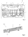
- the in FIG. 1 partly shown dishwasher 20 has a tub 1 for receiving dishes to be washed, also called ware on.
- a lower dish rack (not shown)
- an upper dish rack 2 and a first embodiment 3 of a cutlery drawer according to the invention are arranged in a conventional manner, wherein in the vertical direction of the upper crockery basket 2 above the lower crockery basket, not shown, and the cutlery drawer 3 above of the upper crockery basket 2 is arranged.
- the baskets and the cutlery drawer 3 are received in the tub 1 so that they can be at least partially pulled out of the tub 1 for loading and unloading.
- the baskets casters (not shown) may be provided, which are arranged on the side walls of the tub 1.
- the cutlery drawer 3 comprises a frame 4 and a receiving part 5 connected to the frame 4.
- the frame 4 consists, for example, of a bent metal rod and rests laterally on the rollers, not shown.
- the receiving part 5 is preferably designed in three parts and comprises a central part 6, a first wing 7 and a second wing 8, which are arranged laterally on the central part 6.
- the middle part 6 is fixed to the frame 4, and the wings 7, 8 are opposite to the central part 6 in a below with reference to the FIGS. 2 to 4 way described movably arranged.
- Both the central part 6 and the wings 7, 8 have a plurality of ribs, each forming a kind of basket in which small dishes can be accommodated.
- the ribs or the middle part 6 and the wings 7, 8 consist e.g. made of plastic and can be produced for example by injection molding.
- the bottom of the middle part 6 is in horizontal starting position of the wings 7, 8 preferably lower than the bottoms of the wings 7, 8, so that the middle part 6 and larger crockery, such.
- the wings 7, 8 are movable relative to the central part 6, so that the receiving part 5 can assume different configurations. This is in the FIGS. 2 to 4 illustrated.
- FIG. 2 also shows in FIG. 1 illustrated configuration of the receiving part 5 of the cutlery drawer 3.
- the wings 7, 8 are in their horizontal starting position and extend from the central part 6 laterally outwards, the bottoms of the wings 7, 8 extend horizontally.
- in the cutlery drawer 3 is relatively much space for receiving cutlery and the like.
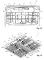
- FIG. 3 shows a second configuration of the receiving part 5, in which the two wings 7, 8 are pivoted relative to the central part 6, that they projecting obliquely upward from the middle part 6, ie their bottoms rise away from the middle part 6 or towards the outside. They are inclined relative to the bottom of the middle part 6 obliquely upwards.
- the two wings 7, 8 are pivoted relative to the central part 6, that they projecting obliquely upward from the middle part 6, ie their bottoms rise away from the middle part 6 or towards the outside. They are inclined relative to the bottom of the middle part 6 obliquely upwards.
- larger spoons with the Laffe must be arranged inwardly in the wings 7, 8.
- FIG. 4 shows finally a third configuration in which one of the wings, in the present example, the first wing 7, is inserted in the horizontal direction in the middle part 6, while the second wing 8 as in in FIG. 3 shown second configuration obliquely upwardly and outwardly from the central portion 6 protrudes.
- the space in the cutlery drawer 3 and in its receiving part 5 is further reduced, but stands for more to be set in the upper crockery basket 2 dishes 21 even more space upwards.
- FIG. 5 illustrates which the cutlery drawer 3 and the receiving part 5 in the configuration according to FIG. 4 shows.
- FIG. 5 It will be seen that with the shown configuration of the cutlery drawer 3 in the upper crockery basket 2, relatively large items to be washed 21 can be adjusted, such as, for example, long-handled glasses.
- one or both wings 7, 8 can be pivoted downwards relative to the middle part 6 so that even on the wings 7, 8 small dishes can be parked.
- the inventive cutlery drawer 3 guide means 22 which are preferably designed as slide guide (s) (also known as slide mechanism).
- slide guide also known as slide mechanism.
- a slotted guide 22 is provided in each case. If, for the sake of simplicity, only embodiments for the front side or the front wall of the receiving part 5 or of the middle part 6 and the wings 6, 7 of the cutlery drawer 3 are made below, the same applies to those on the rear side (s) / rear wall or rear walls arranged slotted guide.
- the slotted guide 22 has a first groove 12.1 with a curved section 23.1 with two end points which lie substantially one over the other at different heights.
- a first sliding block 10.1 is forcibly guided.
- the first groove 12.1 is arranged on an inner side (or outer side) of a front wall of the middle part 6, specifically in a region near the first wing 7.
- the first groove 12.1 is preferably designed in the form of a separate groove element 24, as shown in FIG FIG. 6 is shown, and which on the inside (or outside) of the front wall of the middle part 6 is attached.
- the first sliding block 10.1 is in turn arranged on an outer side (or inner side) of a front wall of the first wing 7, specifically in the transverse direction substantially in the middle.
- the first sliding block 10.1 may also be arranged on the inside (or outside) of the front wall of the central part 6 and the first groove 12.1 also on the outside (or inside) of the front wall of the first wing 7.
- first sliding block 10.1 In the in FIG. 2 shown horizontal starting position of the first wing 7 is the first sliding block 10.1 at unspecified lower end point of the curved portion 23.1 of the first groove 12.1.
- first sliding block 10.1 is guided along the curved section 23.1 of the first groove 12.1 until it comes to lie in its upper end point, as shown in FIG FIG. 3 is shown.
- the first groove 12.1 furthermore has a section running inwardly in a transverse direction from the curved section 23.1, towards the middle of the middle part 6 or receiving part 5 extending elongated portion 25 with a third, unspecified end point.
- the elongate portion 25 is (slightly) bent up or lowered towards its end, so that the first sliding block 10.1 can not easily slide back from the third end point along the elongated portion 25 when it has come to rest in the third end point ,
- the first guide block 10.1 is guided first the curved section 23.1 and then the elongated section 25 up to its end point, as shown in FIG FIG. 4 is shown.
- the slotted guide 22 has a second groove 12.2 with a curved portion 23.2, for which the above with respect to the curved portion 23.1 of the first groove 12.1 applies, except that the curved portion 23.2 mirrored to the curved portion 23.1 is aligned. Furthermore, the slotted guide 22 has a second sliding block 10.2, which is forcibly guided in the second groove 12.2 or the curved section 23.2.
- the sliding block 10.2 is preferably arranged according to the sliding block 10.1 on an outer side (or inner side) of a front wall of the second wing 8, preferably centrally in the transverse direction, while the groove 12.2 is preferably arranged on an inner side (or outer side) of the front wall of the middle section 6 and Although preferred in a second wing 8 near range.
- the second groove 12.2 is preferably also executed separate groove element 24, as exemplified in FIG. 6 is shown.
- the second sliding block 10.2 can be arranged on the middle part 6 and the second groove 12.2 on the second wing 8, as described above for the first wing 7.
- the second wing 8 is pivoted upwards, in which the second sliding block 10.2 is moved upward from the lower end point of the second groove 12.2 in the curved section 23.2 and comes to lie in the upper end point of the second groove 12.2.
- the groove 12.2 can also have a substantially transversely inwardly extending elongated section, such as the elongate section 25 of the first groove 12.1, and reference is made to the above remarks on the elongated section 25 ,
- the slotted guide 22 preferably has a third groove 11 extending on an inner side (or outer side) of the front wall of the central part 6 in the transverse direction and in a third sliding block 9.1, on an outer side (or inner side) of the front wall of the first wing 7 is arranged, and a fourth sliding block 9.2, which is arranged on an outer side (or inner side) of the outer wall of the second wing 8, are positively guided.
- the third groove 11 preferably extends in an upper region of the front wall of the middle part 6.
- the sliding blocks 9.1 and 9.2 are preferably on middle-part-side end regions of the wings 7, 8 arranged.
- the third groove 11 is preferably formed as a separate groove element 24, as in FIG. 6 is shown.
- the third groove 11 and the sliding blocks 9.1, 9.2 serve to stabilize the movements of the wings 7, 8. If the wings 7, 8 are pivoted, then the sliding blocks 9.1, 9.2 remain in the end points of the third groove 11. If the wings 7, 8 but shifted inward, so the sliding blocks 9.1, 9.2 along the third groove 11 move inward.
- the wings 7, 8 can be adjusted in a simple manner and with only one hand.
- the wings 7, 8 may be provided with a handle, in particular laterally or on the respective front wall.
- grooves 12.1, 12.2, 11 are preferably for reinforcement wires or corresponding reinforcing elements introduced, in particular snapped.
- FIG. 6 shows, as indicated above, a groove element 24 of the slotted guide 22, which is applied as a separate part in each case on the rear wall and front wall of the middle part 6 of the cutlery drawer 3, in particular plugged, and advantageously can be prepared separately, for example by injection molding.
- the groove element 24 has the first groove 12.1 and spaced apart in the transverse direction, the second groove 12.2. Furthermore, the groove element 24 has the third groove 11 extending from the center on both sides in the transverse direction. Reference is made to the above description of the grooves 12.1, 12.2, 11.
- the separate production of the groove elements 24 and the middle part 6 makes it possible to achieve a better demolding of the injection-molded parts.
- FIG. 7 shows in particular the design of the bottoms of the wings 7, 8 and the middle part 6 with unspecified ribs.
- the ribs are, in the usual way, designed so that they form a support for cutlery or dishes, but not obstruct the flow of process water as possible.
- each holding rake 14a-14f has two elongated, mutually parallel supports 15a, 15b provided for mounting to the bottom of the cutlery drawer, interconnected by cross braces 16 and from which upwardly extending rods or needles 17 protrude Rods / needles 17 may be different.
- each holder rake 14a-14f may also comprise more than two carriers. Between adjacent bars or needles 17 can be successively (along the carrier 15 a, 15 b) introduced cutlery in a lateral position and held individually (see FIG. 13 ).
- Each of the racks 14a-14f may be positioned by the user in a variety of positions and orientations in the cutlery drawer 3, as shown in FIGS FIGS. 14 and 15 is illustrated, to which reference is made below.
- FIGS. 8 to 13 essentially correspond to the FIGS. 1 to 7 However, they show a second embodiment 3 'of the inventive cutlery drawer.
- this embodiment 3 ' is now in the FIGS. 8 and 12 the storage of the frame 4 'is explicitly shown on rollers 28 provided on the side walls of the tub 1 of the dishwasher 20'.
- the cutlery drawer 3 ' according to the second embodiment has a receiving part 5' with a middle part 6 'and two wings 7, 8.
- the guide means 22 'instead of the third groove 11 of the first embodiment 3, which receives the sliding blocks 9.1, 9.2 of the first wing 7 and the second wing 8
- two grooves 11.1' and 11.2 '(third groove 11.1' and fourth groove 11.2 ') are provided, which extend substantially at the same height in the transverse direction and are preferably provided in an upper
- the groove 11.2 ' can be made substantially shorter than the groove 11.1'.
- a groove element corresponding to the in FIG. 6 for the first embodiment 3 shown groove member 24 corresponds, instead of the groove 11, the two grooves 11.1 'and 11.2' on.
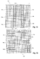
- FIGS. 14 and 15 show in the cutlery drawer 3, 3 'mounted holding rake 14a - 14f in different positions.
- the holding rakes 14a-14f are positioned in two rows, analogous to FIG FIG. 7 and FIG. 13
- the holding rakes 14a-14f are arranged in different positions.
- the holding ridges 14f, 14c, 14b, 14a are arranged at right angles to each other while the holding ridges 14f, 14e and 14d are arranged parallel to one another.
- one of the holding rakes 14a-14f can be inserted in the front area of the cutlery drawer 3, 3 'and serve to hold coffee spoons so that the user does not pull out the entire cutlery drawer 3, 3' in order to load the coffee spoons into the dishwasher 20, 20 ' but only the front area.
- FIGS. 14 and 15 illustrate further that the receiving part 5, 5 'of the cutlery drawer 3, 3' may consist only of a central part 6, 6 'and a wing 7, ie the dimensions of the central part 6, 6' in the transverse direction are in this case such that the middle part 6, 6 'replaces the second wing.
- a region 27 of the receiving part 5, 5 'of the cutlery drawer 3, 3' preferably has a higher static friction than the remaining regions of the receiving part 5, 5 '.
- the arranged in this region 27 ribs 26 have a higher static friction than the remaining, unspecified ribs of the receiving part 5, 5 ', by being preferably from non-slip or slip-resistant, (especially "softer") material such as silicone or coated with such a material at least on its upper side.
- the non-slip region 27 or the ribs 26 are provided in one or both wings 7, 8. This can advantageously be prevented that in this area 27 or on the ribs 26 stored cutlery, such as a knife with its handle, in the middle part 6, 6 'slips.
Abstract
Die Erfindung betrifft eine Besteckschublade (3; 3') für einen Geschirrspüler (20; 20'), umfassend einen Aufnahmeteil (5; 5') zur Aufnahme von zu spülenden Geschirrteilen, insbesondere Besteck, wobei der Aufnahmeteil (5; 5') einen Mittelteil (6; 6') und einen ersten seitlichen Flügel (7) aufweist, dadurch gekennzeichnet, dass der Aufnahmeteil (5; 5') mit Führungsmitteln (22; 22') versehen ist, über welche der erste Flügel (7) mit dem Mittelteil (6; 6') derart verbunden ist, dass er seitlich verschiebbar und in seiner Neigung gegenüber dem Mittelteil (6; 6') verschwenkbar ist.The invention relates to a cutlery drawer (3, 3 ') for a dishwasher (20, 20'), comprising a receiving part (5, 5 ') for receiving dishes to be washed, in particular cutlery, the receiving part (5, 5') having a Central part (6, 6 ') and a first lateral wing (7), characterized in that the receiving part (5, 5') with guide means (22, 22 ') is provided, via which the first wing (7) with the Middle part (6, 6 ') is connected such that it is laterally displaceable and in its inclination relative to the central part (6, 6') is pivotable.
Description
Die Erfindung betrifft eine Besteckschublade für einen Geschirrspüler. Unter einer Besteckschublade ist dabei eine im weitesten Sinne korbartige Aufnahmevorrichtung zu verstehen, welche zur Aufnahme von Besteck, insbesondere in liegender Position, geeignet ist und die herausziehbar im Geschirrspüler angeordnet werden kann. Die Besteckschublade kann, zumindest bereichsweise, auch zur Aufnahme von anderem Kleingeschirr geeignet sein, wie z.B. Espressotassen.The invention relates to a cutlery drawer for a dishwasher. Under a cutlery drawer is a basket-like receptacle in the broadest sense to understand, which is suitable for receiving cutlery, especially in a recumbent position, and which can be arranged to be pulled out in the dishwasher. The cutlery drawer may, at least in certain areas, also be suitable for receiving other small crockery, such as e.g. Espresso cups.
Aus der europäischen Patentanmeldung
Es ist Aufgabe der Erfindung eine Besteckschublade für einen Geschirrspüler bereitzustellen, deren Aufnahmevolumen flexibel eingestellt werden kann, sodass Art, Grösse und Ausdehnung des zu spülenden Geschirrs berücksichtigt werden kann, insbesondere desjenigen Geschirrs, welches in einen unmittelbar unter der Besteckschublade angeordneten Geschirrkorb eines Geschirrspülers gestellt werden soll, wobei die Besteckschublade weiterhin Aufnahmevolumen zur Aufnahme von Besteck und gegebenenfalls Kleingeschirr wie z.B. Espressotassen zur Verfügung stellen soll.It is an object of the invention to provide a cutlery drawer for a dishwasher whose receiving volume can be flexibly adjusted so that the type, size and extent of the dishes to be washed can be taken into account, in particular those dishes which are placed in a arranged directly below the cutlery drawer crockery of a dishwasher should, the cutlery drawer continue recording volume for receiving cutlery and, if necessary, small dishes such Espressotassen should provide.
Diese Aufgabe wird durch eine Besteckschublade mit den Merkmalen des Anspruchs 1 gelöst.This object is achieved by a cutlery drawer with the features of
Die erfindungsgemässe Besteckschublade umfasst einen Aufnahmeteil zur Aufnahme von zu spülenden Geschirrteilen, insbesondere von Besteck und Kleingeschirr wie z.B. Espressotassen. Der Aufnahmeteil umfasst einen Mittelteil und einen ersten seitlichen Flügel. Der Aufnahmeteil ist mit Führungsmitteln versehen, über welche der erste Flügel derart mit dem Mittelteil verbunden ist, dass er seitlich bzw. in Querrichtung verschiebbar und in seiner Neigung gegenüber dem Mittelteil verschwenkbar ist. Der erste Flügel ist aus seiner waagerechten Ausgangsstellung zumindest nach oben, bevorzugterweise jedoch auch nach unten verschwenkbar.The inventive cutlery drawer comprises a receiving part for receiving dishes to be washed, in particular cutlery and small dishes such. Espresso cups. The receiving part comprises a central part and a first lateral wing. The receiving part is provided with guide means, via which the first wing is connected to the central part in such a way that it can be displaced laterally or transversely and swiveled in its inclination relative to the central part. The first wing is from its horizontal starting position at least upwards, but preferably also pivoted downwards.
Vorzugsweise ist ein zweiter seitlicher Flügel vorgesehen, der am Mittelteil gegenüber von dem ersten seitlichen Flügel angeordnet ist, wobei der zweite Flügel derart über die Führungsmittel mit dem Mittelteil verbunden ist, dass er in seiner Neigung gegenüber dem Mittelteil verschwenkbar und bevorzugt auch seitlich bzw. in Querrichtung verschiebbar ist. Auch der zweite Flügel ist aus seiner waagerechten Ausgangslage vorzugsweise nach oben und nach unten verschwenkbar.Preferably, a second side wing is provided, which is arranged on the central part opposite to the first side wing, wherein the second wing is connected via the guide means with the central part, that it is pivotable in its inclination relative to the central part and preferably also laterally or in Transverse direction is displaced. Also, the second wing is preferably pivoted from its horizontal starting position up and down.
Die Führungsmittel sind vorzugsweise als Kulissenführung ausgestaltet, wobei sowohl der Vorderseite als auch der Rückseite der erfindungsgemässen Besteckschublade bzw. des Aufnahmeteils eine Kulissenführung zugeordnet ist. Zum Verschwenken des ersten Flügels gegenüber dem Mittelteil weist eine jede Kulissenführung bevorzugt eine erste Nut und einen ersten Kulissenstein auf, der in der ersten Nut zwangsgeführt ist. Die erste Nut weist einen gekrümmten Nutabschnitt mit wenigstens zwei Endpunkten auf, über die der erste Kulissenstein nicht hinaus kann, wobei der erste der Endpunkte oberhalb des zweiten Endpunktes angeordnet ist. Die beiden Endpunkte bilden Rastpunkte/ergeben Raststellungen, aus denen der erste Kulissenstein nicht ungewollt, d.h. insbesondere nicht ohne Krafteinwirkung durch den Benutzer, herausgleiten kann. Insbesondere ist die erste Nut in Richtung auf die Mitte des Mittelteils gekrümmt.The guide means are preferably designed as a slide guide, wherein both the front and the back of the inventive cutlery drawer or the receiving part is associated with a slotted guide. To pivot the first wing relative to the middle part, each link guide preferably has a first groove and a first sliding block, which is forcibly guided in the first groove. The first groove has a curved groove portion with at least two end points beyond which the first sliding block can not extend, the first of the end points being located above the second end point. The two end points form detent points / result in detent positions from which the first sliding block does not unintentionally, i. in particular not without force from the user, can slip out. In particular, the first groove is curved in the direction of the center of the middle part.
Zum seitlichen Verschieben des ersten Flügels weist die erste Nut vorzugsweise einen nach innen bzw. in Richtung auf die Mitte des Mittelteils verlaufenden länglichen Abschnitt auf, der zwischen dem ersten und dem zweiten Endpunkt von dem gekrümmten Abschnitt der ersten Nut abzweigt und dessen Ende einen dritten Endpunkt bildet, der ebenfalls einen Rastpunkt für den ersten Kulissenstein bildet.For laterally displacing the first wing, the first groove preferably has an elongated portion extending inwardly toward the center of the central portion, which branches off the curved portion of the first groove between the first and second endpoints and has a third endpoint at its end forms, which also forms a resting point for the first sliding stone.
Dabei sind bevorzugt die erste Nut an dem Mittelteil und der Kulissenstein an dem ersten Flügel angeordnet. Alternativ kann der erste Kulissenstein an dem Mittelteil und die erste Nut an dem ersten Flügel angeordnet sein.In this case, the first groove on the central part and the sliding block are preferably arranged on the first wing. Alternatively, the first sliding block may be arranged on the middle part and the first groove on the first wing.
Vorzugsweise weist die Kulissenführung zum Verschwenken und gegebenenfalls zum seitlichen Verschieben des zweiten Flügels, falls vorgesehen, eine zweite Nut und einen zweiten Kulissenstein auf, die bevorzugt wie für die erste Nut und den ersten Kulissenstein beschrieben ausgeführt und angeordnet sind (jedoch spiegelverkehrt). Ist kein seitliches Verschieben des zweiten Flügels vorgesehen, so kann auf den nach innen verlaufenden länglichen Abschnitt der zweiten Nut verzichtet werden. Ist dagegen nur ein seitliches Verschieben des zweiten Flügels angedacht, so kann bei der zweiten Nut auf den gekrümmten Abschnitt verzichtet werden.Preferably, the slotted guide for pivoting and optionally for lateral displacement of the second wing, if provided, a second groove and a second sliding block, which are preferably designed and arranged as described for the first groove and the first sliding block (but mirror-inverted). Is not a lateral shift of the second Sash provided so can be dispensed with the inwardly extending elongated portion of the second groove. If, on the other hand, only a lateral displacement of the second wing is envisaged, the curved section can be dispensed with in the second groove.
Sowohl die erste Nut als auch die gegebenenfalls vorgesehene zweite Nut können als ein oder mehrere Nutelemente ausgeführt sein, die separat von dem Mittelteil, dem ersten Flügel und dem zweiten Flügel ausgeführt, jedoch am Mittelteil oder an den Flügeln angebracht sind.Both the first groove and the optionally provided second groove may be embodied as one or more groove elements, which are executed separately from the middle part, the first wing and the second wing, but are attached to the middle part or to the wings.
Bei der erfindungsgemässen Besteckschublade lässt sich das Aufnahmevolumen flexibel einstellen, indem der erste Flügel und gegebenenfalls der zweite Flügel verschwenkt oder in Querrichtung verschoben werden. Soll beispielsweise in dem typischerweise in einem Geschirrspüler unterhalb der Besteckschublade vorgesehenen Geschirrkorb hohes Geschirr platziert werden, so können der erste und/oder der zweite Flügel der erfindungsgemässen Besteckschublade nach oben geklappt werden, um hierfür Raum zu schaffen. Genügt dies noch nicht, so können der erste und/oder der zweite Flügel in Querrichtung nach innen verschoben werden, um auf diese Weise noch mehr Platz für hohes, im Geschirrkorb zu platzierendes Geschirr zu schaffen. Ist der Geschirrkorb jedoch nur mit relativ niedrigem Geschirr beladen, so können der erste und/oder der zweite Flügel nach unten geklappt werden, sodass auf den Flügeln nicht nur Besteck, sondern Kleingeschirr platziert werden kann.In the inventive cutlery drawer, the receiving volume can be flexibly adjusted by the first wing and possibly the second wing pivoted or moved in the transverse direction. If, for example, high dishes are to be placed in the dish rack, which is typically provided in a dishwasher below the cutlery drawer, then the first and / or the second wing of the cutlery drawer according to the invention can be folded up in order to make room for this. If this is not enough, the first and / or the second wing can be displaced inwards in the transverse direction, in order to create even more space for high dishes to be placed in the dish rack. However, if the crockery basket is loaded only with relatively low crockery, the first and / or the second wing can be folded down so that not only cutlery, but small crockery can be placed on the wings.
Begriffe wie "oberhalb", "oben", "unterhalb", "unten", "waagerecht", "horizontal", "Querrichtung", "vertikal", "Frontwand", "Rückwand", "Frontseite", "Frontwand" beziehen sich dabei auf die Besteckschublade im in einen Geschirrspüler eingebrachten Zustand.Terms such as "above", "above", "below", "below", "horizontal", "horizontal", "transverse direction", "vertical", "front panel", "rear panel", "front panel", "front panel" thereby on the cutlery drawer in the state brought into a dishwasher.
Weitere vorteilhafte Ausgestaltungen der Erfindung ergeben sich aus den abhängigen Ansprüchen und den anhand der Zeichnungen nachfolgend dargestellten Ausführungsbeispielen. Es zeigen:
-
Fig. 1 eine Vorderansicht der oberen Hälfte des Bottichs eines Geschirrspülers mit einer ersten Ausführungsform der erfindungsgemässen Besteckschublade und oberem Geschirrkorb, -
Fig. 2 eine Vorderansicht des Aufnahmeteils der ersten Ausführungsform der Besteckschublade vonFig. 1 in einer ersten Konfiguration, -
Fig. 3 eine Vorderansicht des Aufnahmeteils der ersten Ausführungsform der Besteckschublade vonFig. 1 in einer zweiten Konfiguration, -
Fig. 4 eine Vorderansicht des Aufnahmeteils der ersten Ausführungsform der Besteckschublade vonFig. 1 in einer dritten Konfiguration, -
Fig. 5 eine Vorderansicht der inFig. 1 dargestellten oberen Hälfte des Bottichs eines Geschirrspülers mit der ersten Ausführungsform der Besteckschublade in der dritten Konfiguration, -
Fig. 6 eine perspektivische Ansicht eines Nutelements der Führungsmittel des ersten Ausführungsbeispiels der Besteckschublade, -
Fig. 7 eine perspektivische Ansicht der ersten Ausführungsform der Besteckschublade von oben, -
Fig. 8 eine Vorderansicht der oberen Hälfte des Bottichs eines Geschirrspülers mit einer zweiten Ausführungsform der erfindungsgemässen Besteckschublade und oberem Geschirrkorb, -
Fig. 9 eine Vorderansicht des Aufnahmeteils der zweiten Ausführungsform der Besteckschublade vonFig. 8 in einer ersten Konfiguration, -
Fig. 10 eine Vorderansicht des Aufnahmeteils der zweiten Ausführungsform der Besteckschublade vonFig. 8 in einer zweiten Konfiguration, -
Fig. 11 eine Vorderansicht des Aufnahmeteils der zweiten Ausführungsform der Besteckschublade vonFig. 8 in einer dritten Konfiguration, -
Fig. 12 eine Vorderansicht der inFig. 8 dargestellten oberen Hälfte des Bottichs eines Geschirrspülers mit der zweiten Ausführungsform der Besteckschublade in der dritten Konfiguration, -
Fig. 13 eine perspektivische Ansicht der zweiten Ausführungsform der Besteckschublade von oben, -
Fig. 14 eine Draufsicht auf den Aufnahmeteil einer erfindungsgemässen Besteckschublade mit Halterechen in einer ersten Konfiguration -
Fig. 15 die Besteckschublade nachFig. 14 mit den Halterechen in einer zweiten Konfiguration und -
Fig. 16 eine Draufsicht auf einen Abschnitt einer erfindungsgemässen Besteckschublade mit einem Bereich höherer Haftreibung.
-
Fig. 1 a front view of the upper half of the tub of a dishwasher with a first embodiment of the inventive cutlery drawer and upper dish rack, -
Fig. 2 a front view of the receiving part of the first embodiment of the cutlery drawer ofFig. 1 in a first configuration, -
Fig. 3 a front view of the receiving part of the first embodiment of the cutlery drawer ofFig. 1 in a second configuration, -
Fig. 4 a front view of the receiving part of the first embodiment of the cutlery drawer ofFig. 1 in a third configuration, -
Fig. 5 a front view of inFig. 1 illustrated upper half of the tub of a dishwasher with the first embodiment of the cutlery drawer in the third configuration, -
Fig. 6 a perspective view of a groove element of the guide means of the first embodiment of the cutlery drawer, -
Fig. 7 a perspective view of the first embodiment of the cutlery drawer from above, -
Fig. 8 a front view of the upper half of the tub of a dishwasher with a second embodiment of the inventive cutlery drawer and upper dish rack, -
Fig. 9 a front view of the receiving part of the second embodiment of the cutlery drawer ofFig. 8 in a first configuration, -
Fig. 10 a front view of the receiving part of the second embodiment of the cutlery drawer ofFig. 8 in a second configuration, -
Fig. 11 a front view of the receiving part of the second embodiment of the cutlery drawer ofFig. 8 in a third configuration, -
Fig. 12 a front view of inFig. 8 illustrated upper half of the tub of a dishwasher with the second embodiment of the cutlery drawer in the third configuration, -
Fig. 13 a perspective view of the second embodiment of the cutlery drawer from above, -
Fig. 14 a plan view of the receiving part of an inventive cutlery drawer with holding rakes in a first configuration -
Fig. 15 the cutlery drawer afterFig. 14 with the holding rakes in a second configuration and -
Fig. 16 a plan view of a portion of a cutlery drawer according to the invention with a region of higher static friction.
In den Figuren bezeichnen gleiche Bezugszeichen gleiche oder gleich wirkende Komponenten.In the figures, like reference numerals designate like or equivalent components.
Der in
Die Besteckschublade 3 umfasst einen Rahmen 4 und einen mit dem Rahmen 4 verbundenen Aufnahmeteil 5. Der Rahmen 4 besteht z.B. aus einer gebogenen Metallstange und ruht seitlich auf den nicht dargestellten Rollen. Der Aufnahmeteil 5 ist vorzugsweise dreiteilig ausgeführt und umfasst einen Mittelteil 6, einen ersten Flügel 7 und einen zweiten Flügel 8, die seitlich an dem Mittelteil 6 angeordnet sind. Der Mittelteil 6 ist am Rahmen 4 befestigt, und die Flügel 7, 8 sind gegenüber dem Mittelteil 6 in einer im Folgenden mit Bezug auf die
Sowohl der Mittelteil 6 als auch die Flügel 7, 8 besitzen eine Vielzahl von Rippen, die jeweils eine Art Korb bilden, in welchem Kleingeschirr aufgenommen werden kann. Die Rippen bzw. der Mittelteil 6 und die Flügel 7, 8 bestehen z.B. aus Kunststoff und können beispielsweise im Spritzgussverfahren hergestellt werden. Der Boden des Mittelteils 6 liegt in waagerechter Ausgangsstellung der Flügel 7, 8 vorzugsweise tiefer als die Böden der Flügel 7, 8, so dass der Mittelteil 6 auch sperrigeres Kleingeschirr, wie z.B. Espressotassen sowie Vorlage- und Kochbesteck, aufnehmen kann, während die Flügel 7, 8 zur Aufnahme von üblichem Besteck gedacht sind.Both the
Wie erwähnt, sind die Flügel 7, 8 gegenüber dem Mittelteil 6 beweglich, so dass der Aufnahmeteil 5 verschiedene Konfigurationen einnehmen kann. Dies ist in den
Dies ist in
Selbstverständlich sind weitere Konfigurationen der Besteckschublade 3 bzw. von deren Aufnahmeteil 5 möglich. Zum Beispiel können einer der oder beide Flügel 7, 8 gegenüber dem Mittelteil 6 nach unten verschwenkt werden, sodass auch auf den Flügeln 7, 8 Kleingeschirr abgestellt werden kann.Of course, further configurations of the
Damit die Flügel 7, 8 gegenüber dem Mittelteil 6 bezüglich ihrer Neigung verschwenkbar und in Querrichtung seitlich verschiebbar sind, weist die erfindungsgemässe Besteckschublade 3 Führungsmittel 22 auf, die vorzugsweise als Kulissenführung(en) (auch Kulissenmechanik genannt) ausgestaltet sind. Für die Frontseite der Besteckschublade 3 und für die Rückseite der Besteckschublade 3 ist jeweils eine Kulissenführung 22 vorgesehen. Werden im Folgenden der Einfachheit halber nur Ausführungen für die Frontseite bzw. die Frontwand des Aufnahmeteils 5 bzw. des Mittelteils 6 und der Flügel 6, 7 der Besteckschublade 3 gemacht, so gilt entsprechendes für die auf deren Rückseite(n)/Rückwand bzw. Rückwänden angeordnete Kulissenführung.Thus, the
Zum Verschwenken des ersten Flügels 7 gegenüber dem Mittelteil 6 weist die Kulissenführung 22 eine erste Nut 12.1 mit einem gekrümmten Abschnitt 23.1 auf mit zwei Endpunkten, die auf unterschiedlicher Höhe im Wesentlichen übereinander liegen. In der ersten Nut 12.1 ist ein erster Kulissenstein 10.1 zwangsgeführt. Vorzugsweise ist die erste Nut 12.1 an einer Innenseite (oder Aussenseite) einer Frontwand des Mittelteils 6 angeordnet und zwar insbesondere in einem dem ersten Flügel 7 nahen Bereich. Die erste Nut 12.1 ist vorzugsweise in Form eines separaten Nutelements 24 ausgeführt, wie es in
In der in
Um den ersten Flügel 7 seitlich in den Mittelteil 6 hinein bzw. entlang des Mittelteils 6 verschieben zu können, weist die erste Nut 12.1 ferner einen von dem gekrümmten Abschnitt 23.1 im Wesentlichen in Querrichtung nach innen verlaufenden, sich zur Mitte des Mittelteils 6 bzw. Aufnahmeteils 5 erstreckenden länglichen Abschnitt 25 mit einem dritten, nicht näher bezeichneten Endpunkt auf. Vorzugsweise ist der längliche Abschnitt 25 (leicht) nach oben gebogen bzw. gegen sein Ende hin abgesenkt, sodass der erste Kulissenstein 10.1 nicht einfach wieder von dem dritten Endpunkt den länglichen Abschnitt 25 entlang zurückgleiten kann, wenn er in dem dritten Endpunkt zu liegen gekommen ist.In order to be able to displace the
Um den ersten Flügel 7 also seitlich in den Mittelteil 6 hinein zu verschieben, wird der erste Führungsstein 10.1 erst den gekrümmten Abschnitt 23.1 und dann den länglichen Abschnitt 25 bis zu dessen Endpunkt geführt, wie dies in
Zum Verschwenken des zweiten Flügels 8 weist die Kulissenführung 22 eine zweite Nut 12.2 mit einem gekrümmten Abschnitt 23.2 auf, für den das oben in Bezug auf den gekrümmten Abschnitt 23.1 der ersten Nut 12.1 Gesagte gilt, bis auf dass der gekrümmte Abschnitt 23.2 spiegelverkehrt zum gekrümmten Abschnitt 23.1 ausgerichtet ist. Ferner weist die Kulissenführung 22 einen zweiten Kulissenstein 10.2 auf, der in der zweiten Nut 12.2 bzw. dem gekrümmten Abschnitt 23.2 zwangsgeführt ist.For pivoting the
Der Kulissenstein 10.2 ist vorzugsweise entsprechend dem Kulissenstein 10.1 an einer Aussenseite (oder Innenseite) einer Frontwand des zweiten Flügels 8 angeordnet und zwar in Querrichtung bevorzugt mittig, während die Nut 12.2 vorzugsweise an einer Innenseite (oder Aussenseite) der Frontwand des Mittelteils 6 angeordnet ist und zwar bevorzugt in einem dem zweiten Flügel 8 nahen Bereich. Die zweite Nut 12.2 ist dabei vorzugsweise ebenfalls separates Nutelement 24 ausgeführt, wie es beispielhaft in
Analog zum ersten Flügel 7 wird der zweite Flügel 8 nach oben verschwenkt, in dem der zweite Kulissenstein 10.2 von dem unteren Endpunkt der zweiten Nut 12.2 in dem gekrümmten Abschnitt 23.2 nach oben bewegt wird und im oberen Endpunkt der zweiten Nut 12.2 zu liegen kommt. Soll der zweite Flügel 8 auch seitlich nach innen verschiebbar sein, so kann die Nut 12.2 ebenfalls einen im Wesentlich in Querrichtung nach innen verlaufenden länglichen Abschnitt wie den länglichen Abschnitt 25 der ersten Nut 12.1 aufweisen und es wird auf die obigen Ausführungen zum länglichen Abschnitt 25 verwiesen.Analogously to the
Ferner weist die Kulissenführung 22 vorzugsweise eine dritte Nut 11 auf, die sich an einer Innenseite (oder Aussenseite) der Frontwand des Mittelteils 6 in Querrichtung erstreckt und in der ein dritter Kulissenstein 9.1, der an einer Aussenseite (oder Innenseite) der Frontwand des ersten Flügels 7 angeordnet ist, und ein vierter Kulissenstein 9.2, der an einer Aussenseite (oder Innenseite) der Aussenwand des zweiten Flügels 8 angeordnet ist, zwangsgeführt sind. Die dritte Nut 11 verläuft vorzugsweise in einem oberen Bereich der Frontwand des Mittelteils 6. Die Kulissensteine 9.1 und 9.2 sind vorzugsweise an mittelteilseitigen Endbereichen der Flügel 7, 8 angeordnet. Die dritte Nut 11 ist vorzugsweise als separates Nutelement 24 ausgebildet, wie es in
Selbstverständlich ist, wie eingangs erwähnt, an der Rückwand der erfindungsgemässen Besteckschublade 3 bzw. von deren Aufnahmeteil 5 eine der Kulissenführung 22 entsprechende Kulissenführung 22 vorgesehen. Mittels der Kulissenführung(en) 22 können die Flügel 7, 8 auf einfache Weise und mit nur einer Hand verstellt werden. Zur Verstellung der Flügel 7, 8 können die Flügel 7, 8 jeweils - insbesondere seitlich oder an der jeweiligen Frontwand - mit einem Griff versehen sein.Of course, as mentioned above, provided on the rear wall of the
In die Nuten 12.1, 12.2, 11 sind zur Verstärkung vorzugsweise Drähte oder entsprechende Verstärkungselemente eingebracht, insbesondere eingeschnappt.In the grooves 12.1, 12.2, 11 are preferably for reinforcement wires or corresponding reinforcing elements introduced, in particular snapped.
Die perspektivische Darstellung der
Weiter sind in der Besteckschublade 3 mehrere entfernbare Halterechen 14a - 14f vorgesehen (vergleiche auch
Die
Die Besteckschublade 3' unterscheidet sich von der in den
Die
Die
Gemäss
Claims (18)
Priority Applications (1)
| Application Number | Priority Date | Filing Date | Title |
|---|---|---|---|
| EP20130001879 EP2789286A1 (en) | 2013-04-11 | 2013-04-11 | Cutlery drawer for a dishwasher |
Applications Claiming Priority (1)
| Application Number | Priority Date | Filing Date | Title |
|---|---|---|---|
| EP20130001879 EP2789286A1 (en) | 2013-04-11 | 2013-04-11 | Cutlery drawer for a dishwasher |
Publications (1)
| Publication Number | Publication Date |
|---|---|
| EP2789286A1 true EP2789286A1 (en) | 2014-10-15 |
Family
ID=48092667
Family Applications (1)
| Application Number | Title | Priority Date | Filing Date |
|---|---|---|---|
| EP20130001879 Pending EP2789286A1 (en) | 2013-04-11 | 2013-04-11 | Cutlery drawer for a dishwasher |
Country Status (1)
| Country | Link |
|---|---|
| EP (1) | EP2789286A1 (en) |
Cited By (6)
| Publication number | Priority date | Publication date | Assignee | Title |
|---|---|---|---|---|
| US20150245761A1 (en) * | 2012-09-26 | 2015-09-03 | Foshan Shunde Midea Washing Appliances Mfg. Co., Ltd. | Tray supporting apparatus for dishwasher, cutlery tray assembly and dishwasher |
| WO2017030355A1 (en) | 2015-08-18 | 2017-02-23 | Lg Electronics Inc. | Rack and dishwasher including the same |
| EP3175766A1 (en) | 2015-12-02 | 2017-06-07 | Miele & Cie. KG | Cutlery drawer for a dishwasher |
| EP3175765A1 (en) | 2015-12-02 | 2017-06-07 | Miele & Cie. KG | Crockery basket, especially cutlery drawer for a dishwasher |
| WO2018082321A1 (en) * | 2016-11-01 | 2018-05-11 | 佛山市顺德区美的洗涤电器制造有限公司 | Cutlery tray assembly for use in dishwasher and dishwasher provided with same |
| EP3409182A1 (en) | 2017-06-01 | 2018-12-05 | Miele & Cie. KG | Dish rack, in particular cutlery drawer |
Citations (5)
| Publication number | Priority date | Publication date | Assignee | Title |
|---|---|---|---|---|
| EP1460929A1 (en) * | 2001-12-28 | 2004-09-29 | BSH Bosch und Siemens Hausgeräte GmbH | Cutlery basket for a dishwasher |
| DE102006055352A1 (en) * | 2006-11-23 | 2008-05-29 | BSH Bosch und Siemens Hausgeräte GmbH | Cutlery basket for a dishwasher and dishwasher |
| EP2433549A1 (en) | 2008-12-18 | 2012-03-28 | Miele & Cie. KG | Cutlery drawer for a dishwasher |
| DE102011081774A1 (en) * | 2011-08-30 | 2013-02-28 | BSH Bosch und Siemens Hausgeräte GmbH | Dishwasher, particularly domestic dishwasher for cleaning dishes or cutlery, has flat receiving structure for horizontal support of small washing goods pieces, particularly cutlery pieces |
| EP2754377A1 (en) | 2013-01-09 | 2014-07-16 | Miele & Cie. KG | Cutlery drawer for a dishwasher |
-
2013
- 2013-04-11 EP EP20130001879 patent/EP2789286A1/en active Pending
Patent Citations (5)
| Publication number | Priority date | Publication date | Assignee | Title |
|---|---|---|---|---|
| EP1460929A1 (en) * | 2001-12-28 | 2004-09-29 | BSH Bosch und Siemens Hausgeräte GmbH | Cutlery basket for a dishwasher |
| DE102006055352A1 (en) * | 2006-11-23 | 2008-05-29 | BSH Bosch und Siemens Hausgeräte GmbH | Cutlery basket for a dishwasher and dishwasher |
| EP2433549A1 (en) | 2008-12-18 | 2012-03-28 | Miele & Cie. KG | Cutlery drawer for a dishwasher |
| DE102011081774A1 (en) * | 2011-08-30 | 2013-02-28 | BSH Bosch und Siemens Hausgeräte GmbH | Dishwasher, particularly domestic dishwasher for cleaning dishes or cutlery, has flat receiving structure for horizontal support of small washing goods pieces, particularly cutlery pieces |
| EP2754377A1 (en) | 2013-01-09 | 2014-07-16 | Miele & Cie. KG | Cutlery drawer for a dishwasher |
Cited By (12)
| Publication number | Priority date | Publication date | Assignee | Title |
|---|---|---|---|---|
| US20150245761A1 (en) * | 2012-09-26 | 2015-09-03 | Foshan Shunde Midea Washing Appliances Mfg. Co., Ltd. | Tray supporting apparatus for dishwasher, cutlery tray assembly and dishwasher |
| US9380926B2 (en) * | 2012-09-26 | 2016-07-05 | Foshan Shunde Midea Washing Appliances Mfg. Co., Ltd. | Tray supporting apparatus for dishwasher, cutlery tray assembly and dishwasher |
| WO2017030355A1 (en) | 2015-08-18 | 2017-02-23 | Lg Electronics Inc. | Rack and dishwasher including the same |
| AU2016307599B2 (en) * | 2015-08-18 | 2018-09-20 | Lg Electronics Inc. | Rack and dishwasher including the same |
| US10779705B2 (en) | 2015-08-18 | 2020-09-22 | Lg Electronics Inc. | Rack and dishwasher including the same |
| EP3175766A1 (en) | 2015-12-02 | 2017-06-07 | Miele & Cie. KG | Cutlery drawer for a dishwasher |
| EP3175765A1 (en) | 2015-12-02 | 2017-06-07 | Miele & Cie. KG | Crockery basket, especially cutlery drawer for a dishwasher |
| DE102015120897A1 (en) | 2015-12-02 | 2017-06-08 | Miele & Cie. Kg | Cutlery drawer for a dishwasher |
| DE102015120890A1 (en) | 2015-12-02 | 2017-06-08 | Miele & Cie. Kg | Dish rack, in particular cutlery drawer for a dishwasher |
| WO2018082321A1 (en) * | 2016-11-01 | 2018-05-11 | 佛山市顺德区美的洗涤电器制造有限公司 | Cutlery tray assembly for use in dishwasher and dishwasher provided with same |
| EP3409182A1 (en) | 2017-06-01 | 2018-12-05 | Miele & Cie. KG | Dish rack, in particular cutlery drawer |
| EP3649912A1 (en) | 2017-06-01 | 2020-05-13 | Miele & Cie. KG | Dish rack, in particular cutlery drawer |
Similar Documents
| Publication | Publication Date | Title |
|---|---|---|
| EP2201887B1 (en) | Cutlery drawer for a dishwasher | |
| EP2754377B1 (en) | Cutlery drawer for a dishwasher | |
| EP2377455B1 (en) | Dishwasher basket insert | |
| EP2789286A1 (en) | Cutlery drawer for a dishwasher | |
| DE102010042409B4 (en) | Dishwasher with a pull-out frame and inserts that can be supported thereon | |
| DE102014223373B3 (en) | Dishwashing and household dishwasher | |
| EP3409182B1 (en) | Dish rack, in particular cutlery drawer | |
| EP2777475A1 (en) | Holding device for the goblet of a glass for insertion in a dish basket of a dishwasher | |
| WO2006010730A1 (en) | Dishwasher comprising a variable device for placing objects that are to be washed | |
| EP2865316A1 (en) | Washing basket | |
| DE102013103707A1 (en) | cutlery basket | |
| DE60130882T2 (en) | Dishwasher with an additional cutlery basket | |
| EP2896345B1 (en) | Tableware receiving device for a dish basket of a water-conducting household appliance, dish basket for a water-conducting household appliance and water-conducting household appliance. | |
| EP3175766A1 (en) | Cutlery drawer for a dishwasher | |
| DE102013211549B4 (en) | dishwasher | |
| EP2250935B1 (en) | Vertical drawer for cupboard section | |
| EP3090677B1 (en) | Cutlery drawer for a dishwasher | |
| DE102014216388A1 (en) | Holding device and Spülgutaufnahme | |
| DE202018003163U1 (en) | Cupboard, in particular cupboard and extract for a cupboard | |
| EP3175763A1 (en) | Dish rack, in particular cutlery drawer | |
| EP2581693B1 (en) | Mount for a food container, in particular a gastronorm container | |
| EP2353444B1 (en) | Cupboard drawer | |
| DE102015120882A1 (en) | Crockery basket, especially cutlery drawer | |
| EP2250931B1 (en) | Cupboard setup device | |
| EP2984980B1 (en) | Rack of a dishwasher |
Legal Events
| Date | Code | Title | Description |
|---|---|---|---|
| PUAI | Public reference made under article 153(3) epc to a published international application that has entered the european phase |
Free format text: ORIGINAL CODE: 0009012 |
|
| 17P | Request for examination filed |
Effective date: 20130411 |
|
| AK | Designated contracting states |
Kind code of ref document: A1 Designated state(s): AL AT BE BG CH CY CZ DE DK EE ES FI FR GB GR HR HU IE IS IT LI LT LU LV MC MK MT NL NO PL PT RO RS SE SI SK SM TR |
|
| AX | Request for extension of the european patent |
Extension state: BA ME |
|
| TPAC | Observations filed by third parties |
Free format text: ORIGINAL CODE: EPIDOSNTIPA |
|
| R17P | Request for examination filed (corrected) |
Effective date: 20141201 |
|
| RBV | Designated contracting states (corrected) |
Designated state(s): AL AT BE BG CH CY CZ DE DK EE ES FI FR GB GR HR HU IE IS IT LI LT LU LV MC MK MT NL NO PL PT RO RS SE SI SK SM TR |
|
| 17Q | First examination report despatched |
Effective date: 20150217 |
|
| STAA | Information on the status of an ep patent application or granted ep patent |
Free format text: STATUS: EXAMINATION IS IN PROGRESS |
|
| RAP1 | Party data changed (applicant data changed or rights of an application transferred) |
Owner name: V-ZUG AG |
|
| STAA | Information on the status of an ep patent application or granted ep patent |
Free format text: STATUS: EXAMINATION IS IN PROGRESS |
|
| STAA | Information on the status of an ep patent application or granted ep patent |
Free format text: STATUS: EXAMINATION IS IN PROGRESS |