EP2788818B1 - Two part camera module - Google Patents
Two part camera module Download PDFInfo
- Publication number
- EP2788818B1 EP2788818B1 EP12808577.6A EP12808577A EP2788818B1 EP 2788818 B1 EP2788818 B1 EP 2788818B1 EP 12808577 A EP12808577 A EP 12808577A EP 2788818 B1 EP2788818 B1 EP 2788818B1
- Authority
- EP
- European Patent Office
- Prior art keywords
- circular
- module
- component
- camera module
- snap
- Prior art date
- Legal status (The legal status is an assumption and is not a legal conclusion. Google has not performed a legal analysis and makes no representation as to the accuracy of the status listed.)
- Not-in-force
Links
Images


Classifications
-
- G—PHYSICS
- G03—PHOTOGRAPHY; CINEMATOGRAPHY; ANALOGOUS TECHNIQUES USING WAVES OTHER THAN OPTICAL WAVES; ELECTROGRAPHY; HOLOGRAPHY
- G03B—APPARATUS OR ARRANGEMENTS FOR TAKING PHOTOGRAPHS OR FOR PROJECTING OR VIEWING THEM; APPARATUS OR ARRANGEMENTS EMPLOYING ANALOGOUS TECHNIQUES USING WAVES OTHER THAN OPTICAL WAVES; ACCESSORIES THEREFOR
- G03B17/00—Details of cameras or camera bodies; Accessories therefor
- G03B17/02—Bodies
-
- G—PHYSICS
- G03—PHOTOGRAPHY; CINEMATOGRAPHY; ANALOGOUS TECHNIQUES USING WAVES OTHER THAN OPTICAL WAVES; ELECTROGRAPHY; HOLOGRAPHY
- G03B—APPARATUS OR ARRANGEMENTS FOR TAKING PHOTOGRAPHS OR FOR PROJECTING OR VIEWING THEM; APPARATUS OR ARRANGEMENTS EMPLOYING ANALOGOUS TECHNIQUES USING WAVES OTHER THAN OPTICAL WAVES; ACCESSORIES THEREFOR
- G03B17/00—Details of cameras or camera bodies; Accessories therefor
- G03B17/02—Bodies
- G03B17/08—Waterproof bodies or housings
-
- H—ELECTRICITY
- H04—ELECTRIC COMMUNICATION TECHNIQUE
- H04N—PICTORIAL COMMUNICATION, e.g. TELEVISION
- H04N23/00—Cameras or camera modules comprising electronic image sensors; Control thereof
- H04N23/57—Mechanical or electrical details of cameras or camera modules specially adapted for being embedded in other devices
-
- G—PHYSICS
- G08—SIGNALLING
- G08B—SIGNALLING SYSTEMS, e.g. PERSONAL CALLING SYSTEMS; ORDER TELEGRAPHS; ALARM SYSTEMS
- G08B13/00—Burglar, theft or intruder alarms
- G08B13/18—Actuation by interference with heat, light, or radiation of shorter wavelength; Actuation by intruding sources of heat, light, or radiation of shorter wavelength
- G08B13/189—Actuation by interference with heat, light, or radiation of shorter wavelength; Actuation by intruding sources of heat, light, or radiation of shorter wavelength using passive radiation detection systems
- G08B13/194—Actuation by interference with heat, light, or radiation of shorter wavelength; Actuation by intruding sources of heat, light, or radiation of shorter wavelength using passive radiation detection systems using image scanning and comparing systems
- G08B13/196—Actuation by interference with heat, light, or radiation of shorter wavelength; Actuation by intruding sources of heat, light, or radiation of shorter wavelength using passive radiation detection systems using image scanning and comparing systems using television cameras
- G08B13/19617—Surveillance camera constructional details
- G08B13/19619—Details of casing
-
- G—PHYSICS
- G08—SIGNALLING
- G08B—SIGNALLING SYSTEMS, e.g. PERSONAL CALLING SYSTEMS; ORDER TELEGRAPHS; ALARM SYSTEMS
- G08B13/00—Burglar, theft or intruder alarms
- G08B13/18—Actuation by interference with heat, light, or radiation of shorter wavelength; Actuation by intruding sources of heat, light, or radiation of shorter wavelength
- G08B13/189—Actuation by interference with heat, light, or radiation of shorter wavelength; Actuation by intruding sources of heat, light, or radiation of shorter wavelength using passive radiation detection systems
- G08B13/194—Actuation by interference with heat, light, or radiation of shorter wavelength; Actuation by intruding sources of heat, light, or radiation of shorter wavelength using passive radiation detection systems using image scanning and comparing systems
- G08B13/196—Actuation by interference with heat, light, or radiation of shorter wavelength; Actuation by intruding sources of heat, light, or radiation of shorter wavelength using passive radiation detection systems using image scanning and comparing systems using television cameras
- G08B13/19634—Electrical details of the system, e.g. component blocks for carrying out specific functions
- G08B13/19636—Electrical details of the system, e.g. component blocks for carrying out specific functions pertaining to the camera
Definitions
- This application is related to packaging of camera modules.
- Camera modules may be used in a variety of applications and industries. As a result, there are a variety of camera modules that are specific to an application and/or industry. These camera modules are not universal or interchangeable. Most of these camera modules have metal parts and have complex assembly mechanisms that use screws and glue. The manufacturing of camera modules using reusable parts and designs may provide low cost effective solutions that may be used in many applications.
- a first part includes a lens assembly, a lens assembly holder, a printed circuit board (PCB) with an image capture device and a terminal block.
- the second part includes mounting elements, a connector shroud, an endcap, and an o-ring.
- the first part and the second part are configured to interconnect using a snap assembly.
- the first part is universal for all device applications and the second part is adaptable/interchangeable for each device application.
- GB 2 433 172 A discloses a modular surveillance camera system, wherein the entire surveillance camera system does not need to be replaced as a unit if the system needs to be reconfigured, replaced, or upgraded.
- US 2005/275725 A1 teaches an O-ring seal seated in the groove of a coupling ring to provide a watertight seal.
- US 2006/177206 A1 discloses a waterproof housing for storing a camera having a lens barrel, wherein the waterproof housing includes a cylindrical lens barrel storage section for storing the lens barrel portion and being formed with a through hole which communicates the outside and the inside of the waterproof housing and a rotatable cylindrical operation ring supported on an outer periphery of the cylindrical lens barrel storage section and provided so as to enclose an outer periphery of a rotary ring on the stored lens barrel for rotating the same.
- CN 1 222 823 C discloses a monitor for a television camera, comprising a camera having a substrate coupled to a support structure, a camera fixed to a substrate holder, and a camera holder protrudes from the camera body.
- the non-limiting embodiments described herein are with respect to camera modules.
- the embodiments and variations described herein, and/or shown in the drawings, are presented by way of example only and are not limiting as to the scope and spirit.
- the camera modules may be used in a number of applications including automobile applications and other environmental exposure applications.
- Applicable parts may be made using known manufacturing methods including for example, thermoplastic molding techniques.
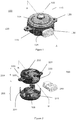
- FIG. 1 shows an assembled circular two part camera module 100.
- the camera module 100 includes a universal camera part 105 and an interchangeable endcap part 110.
- the camera part 105 includes a lens assembly 115 and a lens assembly holder 118.
- the endcap part 110 includes mounting flanges 120 and a connector shroud 125.
- the mounting flanges 120 and a connector shroud 125 may be modified in accordance with the application.
- the connector shroud 125 may be modified to accept an external connector 130.
- the circular design allows for numerous orientations and provides universal mounting for multiple vehicle platforms, for example.
- FIG. 2 shows a partially assembled two part camera module 200.
- the camera module 200 includes a camera part 205 and an endcap part 210.
- the camera part 205 includes a lens assembly (not shown) and lens assembly holder 208 and a camera or image capturing chip or device mounted on a printed circuit board (PCB) 215.
- the PCB 215 with image sensing microchip is placed onto the lens assembly holder 208 with heat activated glue in-between. The positioning is done by computer numerical control (CNC) machinery so that it is precisely aligned to a lens assembly (not shown). The glue is then cured to maintain this alignment.
- a terminal block 220 is positioned on one side of the PCB 215 and is moveably connected to the PCB 215.
- the endcap part 210 includes an endcap 222, mounting elements 225 and a connector shroud 230 as described herein above.
- the endcap part 210 may also include a vent 235 that is used for pressure relief.
- the connector shroud 230 and mounting elements 225 vary in view of the particular mounting and connector environment.
- An external connector 240 connects to the terminal block 220 through the connector shroud 230.
- the endcap part 210 may be changed or adapted for different connectors and mountings.
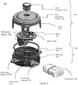
- FIG. 3 shows an exploded view of a two part camera module 300 that includes a universal module 305 and an interchangeable module 310.
- a universal module 305 includes a lens assembly 315 that is screwed into a lens assembly holder 320, a printed circuit board (PCB) 325 and a terminal block 330. Focusing of the lens assembly 315 is accomplished by screwing the lens assembly 315 in and out of the lens assembly holder 320.
- the PCB 325 includes an image capturing device 333.
- the interchangeable module 310 includes an endcap 335 with mounting elements 340 and a connector shroud 345.
- An o-ring 350 is positioned between the universal module 305 and the interchangeable module 310 to provide a water tight seal when the two part camera module 300 is in an assembled state. The o-ring 350 provides a radial seal as opposed to an axial seal.
- a connector 355 is shown that connects to the terminal block 330 via the connector shroud 345.
- the advantage of the radial seal is that the o-ring's sealing function depends on the robust circular shape of both the end cap 335 and lens assembly holder 320 for compression.
- An axial seal depends on the compression created by the attachment of the end cap 335 to the lens assembly holder 320.
- the attachment is facilitated by flexible snap arms 370 and protrusions 375 which provide 4 points of attachment. This may allow the housing to flex in the areas without attachment, providing reduced pressure against the seal in those locations.
- the advantage in using a radial o-ring seal is that there is no stress caused by the o-ring on the snap arms 370 which hold the two halves of the module together. If an axial o-ring seal is used the snap arms 370 will be under constant stress because the o-ring is trying to push the two halves of the module apart, which over time will cause the snap arms 370 to deform and the seal integrity will be lost. In the case of an axial seal, a more robust and expensive connection method needs to be used to attach the two halves together, such as with multiple screws at close intervals, (even with the screws the seal will only be satisfactory near the screws since the plastic will tend to bend and deform in the areas between the screws and reduce the seals integrity over time).
- the o-ring 350 is captured between two tubular surfaces where the structural shape of the parts is creating a seal which is not dependent on the method used to attach the two module halves together.
- the stress is equal through out the entire sealing surface and there are no weak areas that can deform and bend away from the o-ring 350. This means there is considerably more structural integrity when using a radial o-ring seal and the parts will remained sealed indefinitely.
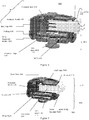
- FIG 4 shows a cross sectional view of a two part camera module 400 taken along line A-A in Figure 1 .
- the two part camera module 400 includes a camera component 405 and a connector component 410.
- the camera component 405 includes a lens assembly 415 positioned in a lens assembly holder 420, a PCB 425, and a terminal block 430.
- the terminal block 430 has terminal pins 433 and terminal legs 437 moveably mounted to the PCB 425.
- the connector component 410 includes an endcap 440 and a connector shroud 445.
- An o-ring 450 sealably connects the camera component 405 and the connector component 410.
- the o-ring seal 450 provides a high quality stress free water tight seal and is a more reliable radial seal as compared to typical axial seals.
- An external connector 455 connects to terminal pins 433 through connector shroud 445.
- FIG. 5 shows a cross sectional view of a two part camera module 500 taken along line B-B in Figure 2 .
- the two part camera module 500 includes a camera component 505 and a connector component 510.
- the camera component 505 includes a lens assembly 515 positioned in a lens assembly holder 520, a PCB 525, and a terminal block 530.
- the connector component 510 includes an endcap 540, a connector shroud 545 and a gore vent 548.
- the gore vent 548 eliminates pressure build-up in two part camera module 500.
- a gore vent may be used that is permeable to air but not to liquids.
- An o-ring 550 sealably connects the camera component 505 and the connector component 510.
- the o-ring seal 550 provides a high quality stress free water tight seal and is a more reliable radial seal as compared to typical axial seals.
- An external connector 555 connects to terminal block 530 through connector shroud 545
- FIG. 6 shows an example fastening process 600 for a two part camera module.
- a two part camera module 605 includes a camera submodule 610 and an endcap submodule 615.
- the camera submodule 610 includes flexible snap arms 620 and the endcap submodule 615 includes protrusions 625.
- the flexible snap arms 620 snap fit with the protrusions 625 to connect together the camera submodule 610 and the endcap submodule 615.
- the snap assembly mechanism allows for a simpler assembly as opposed to glue or screw assemblies. Other snap assembly mechanisms may be used.
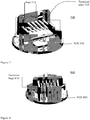
- Figures 7 and 8 show multiple views of a terminal block and PCB.
- Figure 7 shows a front view of an example terminal block 700 mounted on PCB 705.
- the terminal block 700 has terminal pins 710 for connecting with a connector (not shown) and feet 715 for minimal surface contact with the PCB 705.
- Figure 8 shows a rear view of the terminal block 800 mounted on a PCB 805.
- the terminal block 800 has terminal legs 810 for moveably connecting to the PCB 805.
- the terminal legs 810 may be soldered to PCB 805 or other similar means may be used.
- the terminal block 700 or 800 uses the terminal legs 810 and feet 715 to float or move across the PCB 705 or 805 surface to enable alignment. This will enable the body to move a small amount, (enough to align the terminal pins to the connector shroud on the endcap), after the terminal legs 810 have been soldered to the PCB 705 or 805.
- the terminal legs 810 may be metal or other materials suitable for terminals.
- the long flexible terminal legs 810 also ensure there is only minimal stress on the solder joints during movement.
- Figure 9 shows an internal bottom view of an endcap 900 and a bottom view of the terminal block 905.
- the endcap 900 aligns the terminal block 905 to an external connector and/or the connector shroud (neither shown).
- the terminal block 905 has alignment ribs 915 to guide it into endcap alignment pockets 920.
- the alignment ribs 915 will move the terminal block body across a PCB a small amount due to the features described herein above with respect to the terminal block construction.
- the alignment ribs 915 will also secure the terminal block 905 in the endcap 900, resisting connector insertion and removal forces acting upon on it.
- Certain parts may be constructed from plastic or other lightweight moldable materials to reduce weight and cost. These are however non-limiting examples. Parts such as the lens barrel may be made from metal or other materials.
- the methods described herein are not limited to any particular element(s) that perform(s) any particular function(s) and some steps of the methods presented need not necessarily occur in the order shown. For example, in some cases two or more method steps may occur in a different order or simultaneously. In addition, some steps of the described methods may be optional (even if not explicitly stated to be optional) and, therefore, may be omitted. These and other variations of the methods disclosed herein will be readily apparent, especially in view of the description of the camera module package described herein, and are considered to be within the full scope of the invention.
Landscapes
- Physics & Mathematics (AREA)
- General Physics & Mathematics (AREA)
- Engineering & Computer Science (AREA)
- Multimedia (AREA)
- Signal Processing (AREA)
- Studio Devices (AREA)
- Structure And Mechanism Of Cameras (AREA)
- Lens Barrels (AREA)
- Camera Bodies And Camera Details Or Accessories (AREA)
Description
- This application is related to packaging of camera modules.
- Camera modules may be used in a variety of applications and industries. As a result, there are a variety of camera modules that are specific to an application and/or industry. These camera modules are not universal or interchangeable. Most of these camera modules have metal parts and have complex assembly mechanisms that use screws and glue. The manufacturing of camera modules using reusable parts and designs may provide low cost effective solutions that may be used in many applications.
- Described herein is a two part camera module. A first part includes a lens assembly, a lens assembly holder, a printed circuit board (PCB) with an image capture device and a terminal block. The second part includes mounting elements, a connector shroud, an endcap, and an o-ring. The first part and the second part are configured to interconnect using a snap assembly. The first part is universal for all device applications and the second part is adaptable/interchangeable for each device application.
-
GB 2 433 172 A -
US 2005/275725 A1 teaches an O-ring seal seated in the groove of a coupling ring to provide a watertight seal. -
US 2006/177206 A1 discloses a waterproof housing for storing a camera having a lens barrel, wherein the waterproof housing includes a cylindrical lens barrel storage section for storing the lens barrel portion and being formed with a through hole which communicates the outside and the inside of the waterproof housing and a rotatable cylindrical operation ring supported on an outer periphery of the cylindrical lens barrel storage section and provided so as to enclose an outer periphery of a rotary ring on the stored lens barrel for rotating the same. -
CN 1 222 823 C discloses a monitor for a television camera, comprising a camera having a substrate coupled to a support structure, a camera fixed to a substrate holder, and a camera holder protrudes from the camera body. - A more detailed understanding may be had from the following description, given by way of example in conjunction with the accompanying drawings wherein:
-
Figure 1 is an embodiment of an assembled circular two part camera module; -
Figure 2 is an embodiment of a partially assembled two part camera module; -
Figure 3 is an exploded view of an embodiment of a two part camera module; -
Figure 4 is a cross sectional view of an embodiment of an assembled two part camera module; -
Figure 5 is another cross sectional view of an embodiment of an assembled two part camera module with a gore vent; -
Figure 6 shows an example fastening process for an embodiment of a two part camera module; -
Figure 7 shows a front view of an embodiment of a terminal block; -
Figure 8 shows a rear view of an embodiment of a terminal block; and -
Figure 9 shows an internal bottom view of an embodiment of an endcap and a bottom view of an embodiment of a terminal block. - It is to be understood that the figures and descriptions of embodiments of the camera module packaging have been simplified to illustrate elements that are relevant for a clear understanding, while eliminating, for the purpose of clarity, many other elements found in typical electronics packaging. Those of ordinary skill in the art may recognize that other elements and/or steps are desirable and/or required in implementing the camera module packaging. However, because such elements and steps are well known in the art, and because they do not facilitate a better understanding of the camera module packaging, a discussion of such elements and steps is not provided herein.
- The non-limiting embodiments described herein are with respect to camera modules. The embodiments and variations described herein, and/or shown in the drawings, are presented by way of example only and are not limiting as to the scope and spirit. The camera modules may be used in a number of applications including automobile applications and other environmental exposure applications. Applicable parts may be made using known manufacturing methods including for example, thermoplastic molding techniques.
-
Figure 1 shows an assembled circular twopart camera module 100. Thecamera module 100 includes auniversal camera part 105 and aninterchangeable endcap part 110. Thecamera part 105 includes alens assembly 115 and alens assembly holder 118. Theendcap part 110 includesmounting flanges 120 and aconnector shroud 125. Themounting flanges 120 and aconnector shroud 125 may be modified in accordance with the application. For example, theconnector shroud 125 may be modified to accept anexternal connector 130. The circular design allows for numerous orientations and provides universal mounting for multiple vehicle platforms, for example. -
Figure 2 shows a partially assembled twopart camera module 200. Thecamera module 200 includes acamera part 205 and anendcap part 210. Thecamera part 205 includes a lens assembly (not shown) andlens assembly holder 208 and a camera or image capturing chip or device mounted on a printed circuit board (PCB) 215. The PCB 215 with image sensing microchip is placed onto thelens assembly holder 208 with heat activated glue in-between. The positioning is done by computer numerical control (CNC) machinery so that it is precisely aligned to a lens assembly (not shown). The glue is then cured to maintain this alignment. Aterminal block 220 is positioned on one side of thePCB 215 and is moveably connected to the PCB 215. Theendcap part 210 includes anendcap 222,mounting elements 225 and aconnector shroud 230 as described herein above. Theendcap part 210 may also include avent 235 that is used for pressure relief. Theconnector shroud 230 andmounting elements 225 vary in view of the particular mounting and connector environment. Anexternal connector 240 connects to theterminal block 220 through theconnector shroud 230. Theendcap part 210 may be changed or adapted for different connectors and mountings. -
Figure 3 shows an exploded view of a twopart camera module 300 that includes auniversal module 305 and aninterchangeable module 310. Auniversal module 305 includes alens assembly 315 that is screwed into a lens assembly holder 320, a printed circuit board (PCB) 325 and aterminal block 330. Focusing of thelens assembly 315 is accomplished by screwing thelens assembly 315 in and out of the lens assembly holder 320. The PCB 325 includes an image capturingdevice 333. Theinterchangeable module 310 includes anendcap 335 withmounting elements 340 and aconnector shroud 345. An o-ring 350 is positioned between theuniversal module 305 and theinterchangeable module 310 to provide a water tight seal when the twopart camera module 300 is in an assembled state. The o-ring 350 provides a radial seal as opposed to an axial seal. Aconnector 355 is shown that connects to theterminal block 330 via theconnector shroud 345. - The advantage of the radial seal is that the o-ring's sealing function depends on the robust circular shape of both the
end cap 335 and lens assembly holder 320 for compression. An axial seal depends on the compression created by the attachment of theend cap 335 to the lens assembly holder 320. In this case, the attachment is facilitated byflexible snap arms 370 and protrusions 375 which provide 4 points of attachment. This may allow the housing to flex in the areas without attachment, providing reduced pressure against the seal in those locations. - In particular, the advantage in using a radial o-ring seal is that there is no stress caused by the o-ring on the
snap arms 370 which hold the two halves of the module together. If an axial o-ring seal is used thesnap arms 370 will be under constant stress because the o-ring is trying to push the two halves of the module apart, which over time will cause thesnap arms 370 to deform and the seal integrity will be lost. In the case of an axial seal, a more robust and expensive connection method needs to be used to attach the two halves together, such as with multiple screws at close intervals, (even with the screws the seal will only be satisfactory near the screws since the plastic will tend to bend and deform in the areas between the screws and reduce the seals integrity over time). - On the other hand with a radial o-ring seal, the o-
ring 350 is captured between two tubular surfaces where the structural shape of the parts is creating a seal which is not dependent on the method used to attach the two module halves together. The stress is equal through out the entire sealing surface and there are no weak areas that can deform and bend away from the o-ring 350. This means there is considerably more structural integrity when using a radial o-ring seal and the parts will remained sealed indefinitely. -
Figure 4 shows a cross sectional view of a twopart camera module 400 taken along line A-A inFigure 1 . The twopart camera module 400 includes acamera component 405 and aconnector component 410. Thecamera component 405 includes alens assembly 415 positioned in a lens assembly holder 420, aPCB 425, and aterminal block 430. Theterminal block 430 hasterminal pins 433 andterminal legs 437 moveably mounted to thePCB 425. Theconnector component 410 includes anendcap 440 and a connector shroud 445. An o-ring 450 sealably connects thecamera component 405 and theconnector component 410. The o-ring seal 450 provides a high quality stress free water tight seal and is a more reliable radial seal as compared to typical axial seals. Anexternal connector 455 connects toterminal pins 433 through connector shroud 445. -
Figure 5 shows a cross sectional view of a twopart camera module 500 taken along line B-B inFigure 2 . The twopart camera module 500 includes acamera component 505 and aconnector component 510. Thecamera component 505 includes alens assembly 515 positioned in alens assembly holder 520, aPCB 525, and a terminal block 530. Theconnector component 510 includes anendcap 540, aconnector shroud 545 and agore vent 548. Thegore vent 548 eliminates pressure build-up in twopart camera module 500. For example, a gore vent may be used that is permeable to air but not to liquids. An o-ring 550 sealably connects thecamera component 505 and theconnector component 510. The o-ring seal 550 provides a high quality stress free water tight seal and is a more reliable radial seal as compared to typical axial seals. Anexternal connector 555 connects to terminal block 530 throughconnector shroud 545. -
Figure 6 shows anexample fastening process 600 for a two part camera module. A two part camera module 605 includes acamera submodule 610 and anendcap submodule 615. Thecamera submodule 610 includes flexible snap arms 620 and theendcap submodule 615 includes protrusions 625. The flexible snap arms 620 snap fit with the protrusions 625 to connect together thecamera submodule 610 and theendcap submodule 615. The snap assembly mechanism allows for a simpler assembly as opposed to glue or screw assemblies. Other snap assembly mechanisms may be used. -
Figures 7 and 8 show multiple views of a terminal block and PCB.Figure 7 shows a front view of anexample terminal block 700 mounted onPCB 705. Theterminal block 700 has terminal pins 710 for connecting with a connector (not shown) andfeet 715 for minimal surface contact with thePCB 705.Figure 8 shows a rear view of theterminal block 800 mounted on aPCB 805. Theterminal block 800 hasterminal legs 810 for moveably connecting to thePCB 805. For example, theterminal legs 810 may be soldered toPCB 805 or other similar means may be used. - The
terminal block terminal legs 810 andfeet 715 to float or move across thePCB terminal legs 810 have been soldered to thePCB terminal legs 810 may be metal or other materials suitable for terminals. The long flexibleterminal legs 810 also ensure there is only minimal stress on the solder joints during movement. -
Figure 9 shows an internal bottom view of anendcap 900 and a bottom view of theterminal block 905. Theendcap 900 aligns theterminal block 905 to an external connector and/or the connector shroud (neither shown). Theterminal block 905 hasalignment ribs 915 to guide it into endcap alignment pockets 920. Thealignment ribs 915 will move the terminal block body across a PCB a small amount due to the features described herein above with respect to the terminal block construction. Thealignment ribs 915 will also secure theterminal block 905 in theendcap 900, resisting connector insertion and removal forces acting upon on it. - Certain parts may be constructed from plastic or other lightweight moldable materials to reduce weight and cost. These are however non-limiting examples. Parts such as the lens barrel may be made from metal or other materials.
- As described herein, the methods described herein are not limited to any particular element(s) that perform(s) any particular function(s) and some steps of the methods presented need not necessarily occur in the order shown. For example, in some cases two or more method steps may occur in a different order or simultaneously. In addition, some steps of the described methods may be optional (even if not explicitly stated to be optional) and, therefore, may be omitted. These and other variations of the methods disclosed herein will be readily apparent, especially in view of the description of the camera module package described herein, and are considered to be within the full scope of the invention.
- The invention is defined by the appended claims.
Claims (14)
- A circular camera module, comprising:a circular universal first module (105) including at least an image capture device; anda circular second module (110) including mounting elements and a connector shroud (125) whose opening is to an external radial surface of the circular second module (110),wherein the circular universal first module (105) and the circular second module (110) are configured to interconnect using a snap assembly, andthe circular universal first module (105) and the circular second module (110) are sealed against environmental conditions using a radially sealed O-ring, positioned between the circular universal first module (105) and the circular second module (110).
- The circular camera module of claim 1, wherein the mounting elements and the connector shroud (125) are modifiable to connect with different devices (130).
- The circular camera module of claim 1, wherein the circular universal first module (105) includes a lens assembly (115), a lens assembly holder (118), a printed circuit board (PCB) and a terminal block (220).
- The circular camera module of claim 1, wherein the snap assembly includes a first snap fit component including flexible snap arms (370) and a matching snap fit component including corresponding protrusions (375).
- The circular camera module of claim 1, wherein the circular second module (110) further comprises a vent (235) to mitigate internal gas build-up.
- The circular camera module of claim 1, wherein:the circular universal first module (105) is a circular camera component (405) including at least an imager; andthe circular second module (110) is a circular connector component (410) including mounting flanges and the connector shroud (125), whereinthe circular connector component (410) is modifiable to connect with multiple devices, andthe circular camera component (405) is configured for use with multiple devices.
- The circular camera module of claim 6, wherein the snap assembly includes a first snap component including flexible snap arms and a matching snap fit component including corresponding protrusions.
- The circular camera module of claim 6, wherein the mounting flanges (120) and the connector shroud (125) are adapted to connect with the different devices.
- The circular camera module of claim 6, wherein the circular camera component (405) includes a lens assembly (115), a lens assembly holder (118), a printed circuit board (PCB), and a terminal block (220).
- The circular camera module of claim 6, wherein the snap assembly comprises a first snap fit component included in the circular camera component (405) and a matching snap fit component included in the connector component (410).
- The circular camera module of claim 6, wherein the circular connector component (410) further comprises a vent (235) to mitigate internal gas build-up.
- An imaging system, comprising the circular camera module of claim 1, wherein:the circular universal first module (105) is a circular camera component (405) configured to connect with multiple devices; andthe circular second module (110) is an interchangeable mated endcap component, whereinthe interchangeable mated endcap component (440) comprises the mounting elements (120) and the connector shroud (125) that are modifiable to connect with the multiple devices, andthe connector shroud (125) opens to an external radial surface of the interchangeable mated endcap component (440).
- The imaging system of claim 12, wherein the circular camera module (405) and the interchangeable mated endcap component are configured to interconnect using the snap assembly.
- The imaging system of claim 12, wherein the circular camera module (405) includes a lens assembly (115), a lens assembly holder (118), a printed circuit board (PCB) and a terminal block (220).
Applications Claiming Priority (3)
| Application Number | Priority Date | Filing Date | Title |
|---|---|---|---|
| US201161567082P | 2011-12-05 | 2011-12-05 | |
| US13/436,470 US8861951B2 (en) | 2011-12-05 | 2012-03-30 | Two part camera module |
| PCT/US2012/067096 WO2013085796A1 (en) | 2011-12-05 | 2012-11-29 | Two part camera module |
Publications (2)
| Publication Number | Publication Date |
|---|---|
| EP2788818A1 EP2788818A1 (en) | 2014-10-15 |
| EP2788818B1 true EP2788818B1 (en) | 2019-07-24 |
Family
ID=48524083
Family Applications (1)
| Application Number | Title | Priority Date | Filing Date |
|---|---|---|---|
| EP12808577.6A Not-in-force EP2788818B1 (en) | 2011-12-05 | 2012-11-29 | Two part camera module |
Country Status (6)
| Country | Link |
|---|---|
| US (1) | US8861951B2 (en) |
| EP (1) | EP2788818B1 (en) |
| JP (1) | JP6139554B2 (en) |
| CN (1) | CN104136988B (en) |
| CA (1) | CA2858360C (en) |
| WO (1) | WO2013085796A1 (en) |
Families Citing this family (20)
| Publication number | Priority date | Publication date | Assignee | Title |
|---|---|---|---|---|
| WO2013103548A1 (en) | 2012-01-05 | 2013-07-11 | Magna Electronics, Inc. | Camera module for vehicle vision system |
| JP6027329B2 (en) * | 2012-03-30 | 2016-11-16 | シャープ株式会社 | Imaging device |
| US9871999B2 (en) | 2013-07-05 | 2018-01-16 | Flir Systems, Inc. | Modular camera monitoring systems and methods |
| DE102014113992A1 (en) * | 2014-09-26 | 2016-03-31 | Connaught Electronics Ltd. | Housing arrangement for a camera, camera, driver assistance system and motor vehicle |
| KR102248085B1 (en) * | 2014-10-17 | 2021-05-04 | 엘지이노텍 주식회사 | Camera module using for automobile |
| KR101627224B1 (en) * | 2014-10-28 | 2016-06-03 | 세종공업 주식회사 | Multi Function Holder and Connector having Multi Function Holder |
| KR102293357B1 (en) * | 2015-01-12 | 2021-08-25 | 엘지이노텍 주식회사 | Camera module |
| KR102283424B1 (en) * | 2015-01-15 | 2021-07-30 | 엘지이노텍 주식회사 | Camera module using for automobile |
| JP6547948B2 (en) * | 2015-07-07 | 2019-07-24 | ミツミ電機株式会社 | Foreign object adhesion preventing device and camera device provided with the same |
| DE102015115361B4 (en) * | 2015-09-11 | 2025-08-21 | Connaught Electronics Ltd. | Method for producing a camera for a motor vehicle depending on an interface device, camera and motor vehicle |
| CN108476279B (en) | 2016-01-22 | 2022-06-28 | 罗森伯格高频技术有限及两合公司 | camera module |
| US10369936B2 (en) | 2016-04-15 | 2019-08-06 | Veoneer Us, Inc. | Camera arrangements for motor vehicles |
| US10477080B2 (en) | 2016-07-07 | 2019-11-12 | Magna Electronics Inc. | Camera with curled lid and spring element for PCB positioning |
| CN205883388U (en) * | 2016-07-20 | 2017-01-11 | 新科实业有限公司 | Lens assembly and camera module |
| JP6749232B2 (en) * | 2016-12-27 | 2020-09-02 | ホシデン株式会社 | Receptacle connector and camera unit |
| CA3072642A1 (en) * | 2017-09-01 | 2019-03-07 | Mtd Products Inc | Optical sensor housing |
| KR102093416B1 (en) * | 2018-03-30 | 2020-05-27 | (주)파트론 | Camera for mounting on vehicle |
| JP7534082B2 (en) * | 2018-11-15 | 2024-08-14 | フィコサ アダス,ソシエダッド リミタダ ユニペルソナル | Automotive camera housing assembly and method for making same |
| EP4075782A1 (en) | 2021-04-14 | 2022-10-19 | Veoneer Sweden AB | A vehicle camera holding device |
| US12321085B2 (en) * | 2022-04-23 | 2025-06-03 | DeepWater Exploration, Inc. | Submersible camera for underwater vehicles |
Citations (2)
| Publication number | Priority date | Publication date | Assignee | Title |
|---|---|---|---|---|
| CN1222823C (en) * | 2000-03-27 | 2005-10-12 | 埃尔贝兹视频有限公司 | Arched camera with simple structure and positioning |
| US20060177206A1 (en) * | 2004-11-30 | 2006-08-10 | Olympus Corporation | Waterproof housing |
Family Cites Families (26)
| Publication number | Priority date | Publication date | Assignee | Title |
|---|---|---|---|---|
| JPH0687951U (en) * | 1993-05-24 | 1994-12-22 | 株式会社ニコン | Waterproof camera |
| JP4312880B2 (en) * | 1999-06-03 | 2009-08-12 | エルベックスビデオ株式会社 | TV camera |
| US6665455B1 (en) * | 2000-08-14 | 2003-12-16 | Opcom Inc. | Structure of an image-sensing module |
| JP2002262438A (en) * | 2001-03-05 | 2002-09-13 | Yazaki Corp | Intermediate parts for accessory modules and accessory modules |
| US6824317B2 (en) * | 2001-11-21 | 2004-11-30 | Thales Avionics, Inc. | Universal security camera |
| DE20200720U1 (en) * | 2002-01-18 | 2002-05-29 | HARTING Electric GmbH & Co. KG, 32339 Espelkamp | Modular control housing |
| WO2003077530A2 (en) | 2002-03-05 | 2003-09-18 | Hitron Usa | Quick-release sensor assembly and method |
| US7004787B2 (en) * | 2002-06-11 | 2006-02-28 | Henry Milan | Universal computer cable with quick connectors and interchangeable ends, and system and method utilizing the same |
| US7965336B2 (en) | 2002-11-14 | 2011-06-21 | Donnelly Corporation | Imaging system for vehicle |
| US20040169771A1 (en) * | 2003-01-02 | 2004-09-02 | Washington Richard G | Thermally cooled imaging apparatus |
| ATE527556T1 (en) * | 2003-05-22 | 2011-10-15 | Fico Mirrors Sa | IMAGE CAPTURE MODULE SUITABLE FOR MONITORING THE EXTERNAL ENVIRONMENT OF A VEHICLE |
| US6913402B2 (en) * | 2003-08-07 | 2005-07-05 | Stratos International, Inc. | Bulkhead mountable optoelectronic device |
| US8587648B2 (en) | 2004-06-01 | 2013-11-19 | SeeScan, Inc. | Self-leveling camera head |
| US7316590B2 (en) * | 2005-04-21 | 2008-01-08 | Kyocera Wireless Corp. | Data connector with changeable connector key and method of using the same |
| JP2007022364A (en) * | 2005-07-19 | 2007-02-01 | Auto Network Gijutsu Kenkyusho:Kk | Car camera |
| US7387453B2 (en) * | 2005-09-02 | 2008-06-17 | Pelco, Inc. | Camera support and mounting assembly |
| US20070126872A1 (en) | 2005-12-06 | 2007-06-07 | Michael Bolotine | Modular surveillance camera system |
| TWI437301B (en) * | 2006-02-03 | 2014-05-11 | Hitachi Maxell | Camera module |
| JP4249192B2 (en) * | 2006-02-17 | 2009-04-02 | Smk株式会社 | Electrical equipment for module equipment |
| US7983556B2 (en) * | 2006-11-03 | 2011-07-19 | Flextronics Ap Llc | Camera module with contamination reduction feature |
| US7718892B2 (en) * | 2007-04-06 | 2010-05-18 | Flextronics Automotive Inc. | Control module housing |
| JP4497193B2 (en) * | 2007-11-09 | 2010-07-07 | ソニー株式会社 | Camera mounting structure, camera mounting method, and vehicle exterior panel component |
| US8083416B2 (en) * | 2007-11-30 | 2011-12-27 | Adc Telecommunications, Inc. | Hybrid fiber/copper connector system and method |
| US8041201B2 (en) * | 2008-04-03 | 2011-10-18 | Nokia Corporation | Camera module having movable lens |
| JP2009265393A (en) | 2008-04-25 | 2009-11-12 | Yazaki Corp | Electric apparatus module |
| JP5183427B2 (en) * | 2008-11-13 | 2013-04-17 | 京セラ株式会社 | Imaging module |
-
2012
- 2012-03-30 US US13/436,470 patent/US8861951B2/en not_active Expired - Fee Related
- 2012-11-29 JP JP2014545950A patent/JP6139554B2/en not_active Expired - Fee Related
- 2012-11-29 CA CA2858360A patent/CA2858360C/en active Active
- 2012-11-29 EP EP12808577.6A patent/EP2788818B1/en not_active Not-in-force
- 2012-11-29 CN CN201280060044.2A patent/CN104136988B/en not_active Expired - Fee Related
- 2012-11-29 WO PCT/US2012/067096 patent/WO2013085796A1/en not_active Ceased
Patent Citations (2)
| Publication number | Priority date | Publication date | Assignee | Title |
|---|---|---|---|---|
| CN1222823C (en) * | 2000-03-27 | 2005-10-12 | 埃尔贝兹视频有限公司 | Arched camera with simple structure and positioning |
| US20060177206A1 (en) * | 2004-11-30 | 2006-08-10 | Olympus Corporation | Waterproof housing |
Also Published As
| Publication number | Publication date |
|---|---|
| CA2858360A1 (en) | 2013-06-13 |
| US8861951B2 (en) | 2014-10-14 |
| CA2858360C (en) | 2021-01-12 |
| CN104136988B (en) | 2017-07-18 |
| WO2013085796A1 (en) | 2013-06-13 |
| WO2013085796A8 (en) | 2013-12-19 |
| JP6139554B2 (en) | 2017-05-31 |
| CN104136988A (en) | 2014-11-05 |
| JP2015513339A (en) | 2015-05-07 |
| EP2788818A1 (en) | 2014-10-15 |
| US20130142504A1 (en) | 2013-06-06 |
Similar Documents
| Publication | Publication Date | Title |
|---|---|---|
| CA2858360C (en) | Two part camera module | |
| KR102708474B1 (en) | Camera module | |
| KR100995237B1 (en) | Camera device with image sensor sealed from environmental impact | |
| KR102468410B1 (en) | Camera module | |
| EP3384667B1 (en) | Camera module | |
| US20190320096A1 (en) | Camera device and assembling method for same | |
| US12124102B2 (en) | Lens assembly and camera incorporating a lens assembly | |
| CN111405148B (en) | Lens module and electronic device | |
| CN210720982U (en) | Casing, shooting equipment, cloud platform system and movable platform | |
| US12321085B2 (en) | Submersible camera for underwater vehicles | |
| JP2016184081A (en) | Lens unit and camera module | |
| US8811814B2 (en) | Method and system for camera module alignment | |
| JP2008148253A (en) | Camera module, imaging device, and method of assembling the same | |
| KR20180117306A (en) | Camera module | |
| JP6745013B2 (en) | Lens unit and imaging device | |
| CN218416520U (en) | Image pickup apparatus | |
| CN113960732B (en) | Camera module, electronic device and lens barrel processing method | |
| CN111699435B (en) | Waterproof structure for camera, waterproof lens unit, and camera module | |
| JP2006279353A (en) | Solid-state image sensing device, electronic equipment equipped with the same, and method of manufacturing solid-state image sensing device | |
| HK40035101B (en) | Waterproof structure for camera, waterproof lens unit, and camera set |
Legal Events
| Date | Code | Title | Description |
|---|---|---|---|
| PUAI | Public reference made under article 153(3) epc to a published international application that has entered the european phase |
Free format text: ORIGINAL CODE: 0009012 |
|
| 17P | Request for examination filed |
Effective date: 20140703 |
|
| AK | Designated contracting states |
Kind code of ref document: A1 Designated state(s): AL AT BE BG CH CY CZ DE DK EE ES FI FR GB GR HR HU IE IS IT LI LT LU LV MC MK MT NL NO PL PT RO RS SE SI SK SM TR |
|
| DAX | Request for extension of the european patent (deleted) | ||
| STAA | Information on the status of an ep patent application or granted ep patent |
Free format text: STATUS: EXAMINATION IS IN PROGRESS |
|
| 17Q | First examination report despatched |
Effective date: 20170512 |
|
| GRAP | Despatch of communication of intention to grant a patent |
Free format text: ORIGINAL CODE: EPIDOSNIGR1 |
|
| STAA | Information on the status of an ep patent application or granted ep patent |
Free format text: STATUS: GRANT OF PATENT IS INTENDED |
|
| RIC1 | Information provided on ipc code assigned before grant |
Ipc: G08B 13/196 20060101ALI20190114BHEP Ipc: H04N 5/225 20060101ALI20190114BHEP Ipc: G03B 17/08 20060101ALI20190114BHEP Ipc: G03B 17/02 20060101AFI20190114BHEP |
|
| INTG | Intention to grant announced |
Effective date: 20190213 |
|
| GRAJ | Information related to disapproval of communication of intention to grant by the applicant or resumption of examination proceedings by the epo deleted |
Free format text: ORIGINAL CODE: EPIDOSDIGR1 |
|
| STAA | Information on the status of an ep patent application or granted ep patent |
Free format text: STATUS: EXAMINATION IS IN PROGRESS |
|
| GRAR | Information related to intention to grant a patent recorded |
Free format text: ORIGINAL CODE: EPIDOSNIGR71 |
|
| GRAS | Grant fee paid |
Free format text: ORIGINAL CODE: EPIDOSNIGR3 |
|
| STAA | Information on the status of an ep patent application or granted ep patent |
Free format text: STATUS: GRANT OF PATENT IS INTENDED |
|
| INTC | Intention to grant announced (deleted) | ||
| RAP1 | Party data changed (applicant data changed or rights of an application transferred) |
Owner name: FLEXTRONICS AP LLC |
|
| INTG | Intention to grant announced |
Effective date: 20190516 |
|
| GRAA | (expected) grant |
Free format text: ORIGINAL CODE: 0009210 |
|
| STAA | Information on the status of an ep patent application or granted ep patent |
Free format text: STATUS: THE PATENT HAS BEEN GRANTED |
|
| AK | Designated contracting states |
Kind code of ref document: B1 Designated state(s): AL AT BE BG CH CY CZ DE DK EE ES FI FR GB GR HR HU IE IS IT LI LT LU LV MC MK MT NL NO PL PT RO RS SE SI SK SM TR |
|
| REG | Reference to a national code |
Ref country code: GB Ref legal event code: FG4D |
|
| REG | Reference to a national code |
Ref country code: CH Ref legal event code: EP |
|
| REG | Reference to a national code |
Ref country code: DE Ref legal event code: R096 Ref document number: 602012062307 Country of ref document: DE |
|
| REG | Reference to a national code |
Ref country code: AT Ref legal event code: REF Ref document number: 1158895 Country of ref document: AT Kind code of ref document: T Effective date: 20190815 |
|
| REG | Reference to a national code |
Ref country code: IE Ref legal event code: FG4D |
|
| REG | Reference to a national code |
Ref country code: NL Ref legal event code: MP Effective date: 20190724 |
|
| REG | Reference to a national code |
Ref country code: LT Ref legal event code: MG4D |
|
| REG | Reference to a national code |
Ref country code: AT Ref legal event code: MK05 Ref document number: 1158895 Country of ref document: AT Kind code of ref document: T Effective date: 20190724 |
|
| PG25 | Lapsed in a contracting state [announced via postgrant information from national office to epo] |
Ref country code: HR Free format text: LAPSE BECAUSE OF FAILURE TO SUBMIT A TRANSLATION OF THE DESCRIPTION OR TO PAY THE FEE WITHIN THE PRESCRIBED TIME-LIMIT Effective date: 20190724 Ref country code: SE Free format text: LAPSE BECAUSE OF FAILURE TO SUBMIT A TRANSLATION OF THE DESCRIPTION OR TO PAY THE FEE WITHIN THE PRESCRIBED TIME-LIMIT Effective date: 20190724 Ref country code: FI Free format text: LAPSE BECAUSE OF FAILURE TO SUBMIT A TRANSLATION OF THE DESCRIPTION OR TO PAY THE FEE WITHIN THE PRESCRIBED TIME-LIMIT Effective date: 20190724 Ref country code: NO Free format text: LAPSE BECAUSE OF FAILURE TO SUBMIT A TRANSLATION OF THE DESCRIPTION OR TO PAY THE FEE WITHIN THE PRESCRIBED TIME-LIMIT Effective date: 20191024 Ref country code: AT Free format text: LAPSE BECAUSE OF FAILURE TO SUBMIT A TRANSLATION OF THE DESCRIPTION OR TO PAY THE FEE WITHIN THE PRESCRIBED TIME-LIMIT Effective date: 20190724 Ref country code: NL Free format text: LAPSE BECAUSE OF FAILURE TO SUBMIT A TRANSLATION OF THE DESCRIPTION OR TO PAY THE FEE WITHIN THE PRESCRIBED TIME-LIMIT Effective date: 20190724 Ref country code: LT Free format text: LAPSE BECAUSE OF FAILURE TO SUBMIT A TRANSLATION OF THE DESCRIPTION OR TO PAY THE FEE WITHIN THE PRESCRIBED TIME-LIMIT Effective date: 20190724 Ref country code: BG Free format text: LAPSE BECAUSE OF FAILURE TO SUBMIT A TRANSLATION OF THE DESCRIPTION OR TO PAY THE FEE WITHIN THE PRESCRIBED TIME-LIMIT Effective date: 20191024 Ref country code: PT Free format text: LAPSE BECAUSE OF FAILURE TO SUBMIT A TRANSLATION OF THE DESCRIPTION OR TO PAY THE FEE WITHIN THE PRESCRIBED TIME-LIMIT Effective date: 20191125 |
|
| PG25 | Lapsed in a contracting state [announced via postgrant information from national office to epo] |
Ref country code: RS Free format text: LAPSE BECAUSE OF FAILURE TO SUBMIT A TRANSLATION OF THE DESCRIPTION OR TO PAY THE FEE WITHIN THE PRESCRIBED TIME-LIMIT Effective date: 20190724 Ref country code: LV Free format text: LAPSE BECAUSE OF FAILURE TO SUBMIT A TRANSLATION OF THE DESCRIPTION OR TO PAY THE FEE WITHIN THE PRESCRIBED TIME-LIMIT Effective date: 20190724 Ref country code: AL Free format text: LAPSE BECAUSE OF FAILURE TO SUBMIT A TRANSLATION OF THE DESCRIPTION OR TO PAY THE FEE WITHIN THE PRESCRIBED TIME-LIMIT Effective date: 20190724 Ref country code: GR Free format text: LAPSE BECAUSE OF FAILURE TO SUBMIT A TRANSLATION OF THE DESCRIPTION OR TO PAY THE FEE WITHIN THE PRESCRIBED TIME-LIMIT Effective date: 20191025 Ref country code: ES Free format text: LAPSE BECAUSE OF FAILURE TO SUBMIT A TRANSLATION OF THE DESCRIPTION OR TO PAY THE FEE WITHIN THE PRESCRIBED TIME-LIMIT Effective date: 20190724 Ref country code: IS Free format text: LAPSE BECAUSE OF FAILURE TO SUBMIT A TRANSLATION OF THE DESCRIPTION OR TO PAY THE FEE WITHIN THE PRESCRIBED TIME-LIMIT Effective date: 20191124 |
|
| PG25 | Lapsed in a contracting state [announced via postgrant information from national office to epo] |
Ref country code: TR Free format text: LAPSE BECAUSE OF FAILURE TO SUBMIT A TRANSLATION OF THE DESCRIPTION OR TO PAY THE FEE WITHIN THE PRESCRIBED TIME-LIMIT Effective date: 20190724 |
|
| PG25 | Lapsed in a contracting state [announced via postgrant information from national office to epo] |
Ref country code: PL Free format text: LAPSE BECAUSE OF FAILURE TO SUBMIT A TRANSLATION OF THE DESCRIPTION OR TO PAY THE FEE WITHIN THE PRESCRIBED TIME-LIMIT Effective date: 20190724 Ref country code: EE Free format text: LAPSE BECAUSE OF FAILURE TO SUBMIT A TRANSLATION OF THE DESCRIPTION OR TO PAY THE FEE WITHIN THE PRESCRIBED TIME-LIMIT Effective date: 20190724 Ref country code: RO Free format text: LAPSE BECAUSE OF FAILURE TO SUBMIT A TRANSLATION OF THE DESCRIPTION OR TO PAY THE FEE WITHIN THE PRESCRIBED TIME-LIMIT Effective date: 20190724 Ref country code: DK Free format text: LAPSE BECAUSE OF FAILURE TO SUBMIT A TRANSLATION OF THE DESCRIPTION OR TO PAY THE FEE WITHIN THE PRESCRIBED TIME-LIMIT Effective date: 20190724 |
|
| PG25 | Lapsed in a contracting state [announced via postgrant information from national office to epo] |
Ref country code: SM Free format text: LAPSE BECAUSE OF FAILURE TO SUBMIT A TRANSLATION OF THE DESCRIPTION OR TO PAY THE FEE WITHIN THE PRESCRIBED TIME-LIMIT Effective date: 20190724 Ref country code: IS Free format text: LAPSE BECAUSE OF FAILURE TO SUBMIT A TRANSLATION OF THE DESCRIPTION OR TO PAY THE FEE WITHIN THE PRESCRIBED TIME-LIMIT Effective date: 20200224 Ref country code: CZ Free format text: LAPSE BECAUSE OF FAILURE TO SUBMIT A TRANSLATION OF THE DESCRIPTION OR TO PAY THE FEE WITHIN THE PRESCRIBED TIME-LIMIT Effective date: 20190724 Ref country code: SK Free format text: LAPSE BECAUSE OF FAILURE TO SUBMIT A TRANSLATION OF THE DESCRIPTION OR TO PAY THE FEE WITHIN THE PRESCRIBED TIME-LIMIT Effective date: 20190724 |
|
| REG | Reference to a national code |
Ref country code: DE Ref legal event code: R097 Ref document number: 602012062307 Country of ref document: DE |
|
| REG | Reference to a national code |
Ref country code: CH Ref legal event code: PL |
|
| PLBE | No opposition filed within time limit |
Free format text: ORIGINAL CODE: 0009261 |
|
| STAA | Information on the status of an ep patent application or granted ep patent |
Free format text: STATUS: NO OPPOSITION FILED WITHIN TIME LIMIT |
|
| PG2D | Information on lapse in contracting state deleted |
Ref country code: IS |
|
| PG25 | Lapsed in a contracting state [announced via postgrant information from national office to epo] |
Ref country code: MC Free format text: LAPSE BECAUSE OF FAILURE TO SUBMIT A TRANSLATION OF THE DESCRIPTION OR TO PAY THE FEE WITHIN THE PRESCRIBED TIME-LIMIT Effective date: 20190724 Ref country code: LI Free format text: LAPSE BECAUSE OF NON-PAYMENT OF DUE FEES Effective date: 20191130 Ref country code: CH Free format text: LAPSE BECAUSE OF NON-PAYMENT OF DUE FEES Effective date: 20191130 Ref country code: LU Free format text: LAPSE BECAUSE OF NON-PAYMENT OF DUE FEES Effective date: 20191129 |
|
| 26N | No opposition filed |
Effective date: 20200603 |
|
| REG | Reference to a national code |
Ref country code: BE Ref legal event code: MM Effective date: 20191130 |
|
| PG25 | Lapsed in a contracting state [announced via postgrant information from national office to epo] |
Ref country code: SI Free format text: LAPSE BECAUSE OF FAILURE TO SUBMIT A TRANSLATION OF THE DESCRIPTION OR TO PAY THE FEE WITHIN THE PRESCRIBED TIME-LIMIT Effective date: 20190724 |
|
| PG25 | Lapsed in a contracting state [announced via postgrant information from national office to epo] |
Ref country code: IE Free format text: LAPSE BECAUSE OF NON-PAYMENT OF DUE FEES Effective date: 20191129 |
|
| PG25 | Lapsed in a contracting state [announced via postgrant information from national office to epo] |
Ref country code: BE Free format text: LAPSE BECAUSE OF NON-PAYMENT OF DUE FEES Effective date: 20191130 |
|
| PG25 | Lapsed in a contracting state [announced via postgrant information from national office to epo] |
Ref country code: CY Free format text: LAPSE BECAUSE OF FAILURE TO SUBMIT A TRANSLATION OF THE DESCRIPTION OR TO PAY THE FEE WITHIN THE PRESCRIBED TIME-LIMIT Effective date: 20190724 |
|
| PG25 | Lapsed in a contracting state [announced via postgrant information from national office to epo] |
Ref country code: MT Free format text: LAPSE BECAUSE OF FAILURE TO SUBMIT A TRANSLATION OF THE DESCRIPTION OR TO PAY THE FEE WITHIN THE PRESCRIBED TIME-LIMIT Effective date: 20190724 Ref country code: HU Free format text: LAPSE BECAUSE OF FAILURE TO SUBMIT A TRANSLATION OF THE DESCRIPTION OR TO PAY THE FEE WITHIN THE PRESCRIBED TIME-LIMIT; INVALID AB INITIO Effective date: 20121129 |
|
| PG25 | Lapsed in a contracting state [announced via postgrant information from national office to epo] |
Ref country code: MK Free format text: LAPSE BECAUSE OF FAILURE TO SUBMIT A TRANSLATION OF THE DESCRIPTION OR TO PAY THE FEE WITHIN THE PRESCRIBED TIME-LIMIT Effective date: 20190724 |
|
| PGFP | Annual fee paid to national office [announced via postgrant information from national office to epo] |
Ref country code: DE Payment date: 20221128 Year of fee payment: 11 |
|
| PGFP | Annual fee paid to national office [announced via postgrant information from national office to epo] |
Ref country code: GB Payment date: 20231121 Year of fee payment: 12 |
|
| PGFP | Annual fee paid to national office [announced via postgrant information from national office to epo] |
Ref country code: IT Payment date: 20231124 Year of fee payment: 12 Ref country code: FR Payment date: 20231123 Year of fee payment: 12 |
|
| REG | Reference to a national code |
Ref country code: DE Ref legal event code: R119 Ref document number: 602012062307 Country of ref document: DE |
|
| PG25 | Lapsed in a contracting state [announced via postgrant information from national office to epo] |
Ref country code: DE Free format text: LAPSE BECAUSE OF NON-PAYMENT OF DUE FEES Effective date: 20240601 |
|
| PG25 | Lapsed in a contracting state [announced via postgrant information from national office to epo] |
Ref country code: DE Free format text: LAPSE BECAUSE OF NON-PAYMENT OF DUE FEES Effective date: 20240601 |
|
| GBPC | Gb: european patent ceased through non-payment of renewal fee |
Effective date: 20241129 |
|
| PG25 | Lapsed in a contracting state [announced via postgrant information from national office to epo] |
Ref country code: IT Free format text: LAPSE BECAUSE OF NON-PAYMENT OF DUE FEES Effective date: 20241129 |
|
| PG25 | Lapsed in a contracting state [announced via postgrant information from national office to epo] |
Ref country code: GB Free format text: LAPSE BECAUSE OF NON-PAYMENT OF DUE FEES Effective date: 20241129 |
|
| PG25 | Lapsed in a contracting state [announced via postgrant information from national office to epo] |
Ref country code: FR Free format text: LAPSE BECAUSE OF NON-PAYMENT OF DUE FEES Effective date: 20241130 |