EP2787779B1 - Apparatus for regulating transmission power of repeater in long term evolution system - Google Patents
Apparatus for regulating transmission power of repeater in long term evolution system Download PDFInfo
- Publication number
- EP2787779B1 EP2787779B1 EP12854057.2A EP12854057A EP2787779B1 EP 2787779 B1 EP2787779 B1 EP 2787779B1 EP 12854057 A EP12854057 A EP 12854057A EP 2787779 B1 EP2787779 B1 EP 2787779B1
- Authority
- EP
- European Patent Office
- Prior art keywords
- synchronization signal
- repeater
- signal
- power
- lte
- Prior art date
- Legal status (The legal status is an assumption and is not a legal conclusion. Google has not performed a legal analysis and makes no representation as to the accuracy of the status listed.)
- Active
Links
Images



Classifications
-
- H—ELECTRICITY
- H04—ELECTRIC COMMUNICATION TECHNIQUE
- H04B—TRANSMISSION
- H04B7/00—Radio transmission systems, i.e. using radiation field
- H04B7/14—Relay systems
- H04B7/15—Active relay systems
- H04B7/155—Ground-based stations
- H04B7/15528—Control of operation parameters of a relay station to exploit the physical medium
- H04B7/15535—Control of relay amplifier gain
-
- H—ELECTRICITY
- H04—ELECTRIC COMMUNICATION TECHNIQUE
- H04W—WIRELESS COMMUNICATION NETWORKS
- H04W52/00—Power management, e.g. Transmission Power Control [TPC] or power classes
- H04W52/04—Transmission power control [TPC]
- H04W52/06—TPC algorithms
- H04W52/14—Separate analysis of uplink or downlink
- H04W52/143—Downlink power control
-
- H—ELECTRICITY
- H04—ELECTRIC COMMUNICATION TECHNIQUE
- H04W—WIRELESS COMMUNICATION NETWORKS
- H04W52/00—Power management, e.g. Transmission Power Control [TPC] or power classes
- H04W52/04—Transmission power control [TPC]
- H04W52/18—TPC being performed according to specific parameters
-
- H—ELECTRICITY
- H04—ELECTRIC COMMUNICATION TECHNIQUE
- H04W—WIRELESS COMMUNICATION NETWORKS
- H04W52/00—Power management, e.g. Transmission Power Control [TPC] or power classes
- H04W52/04—Transmission power control [TPC]
- H04W52/18—TPC being performed according to specific parameters
- H04W52/24—TPC being performed according to specific parameters using SIR [Signal to Interference Ratio] or other wireless path parameters
- H04W52/245—TPC being performed according to specific parameters using SIR [Signal to Interference Ratio] or other wireless path parameters taking into account received signal strength
-
- H—ELECTRICITY
- H04—ELECTRIC COMMUNICATION TECHNIQUE
- H04W—WIRELESS COMMUNICATION NETWORKS
- H04W52/00—Power management, e.g. Transmission Power Control [TPC] or power classes
- H04W52/04—Transmission power control [TPC]
- H04W52/18—TPC being performed according to specific parameters
- H04W52/24—TPC being performed according to specific parameters using SIR [Signal to Interference Ratio] or other wireless path parameters
- H04W52/246—TPC being performed according to specific parameters using SIR [Signal to Interference Ratio] or other wireless path parameters where the output power of a terminal is based on a path parameter calculated in said terminal
-
- H—ELECTRICITY
- H04—ELECTRIC COMMUNICATION TECHNIQUE
- H04W—WIRELESS COMMUNICATION NETWORKS
- H04W52/00—Power management, e.g. Transmission Power Control [TPC] or power classes
- H04W52/04—Transmission power control [TPC]
- H04W52/38—TPC being performed in particular situations
- H04W52/46—TPC being performed in particular situations in multi-hop networks, e.g. wireless relay networks
-
- H—ELECTRICITY
- H04—ELECTRIC COMMUNICATION TECHNIQUE
- H04W—WIRELESS COMMUNICATION NETWORKS
- H04W52/00—Power management, e.g. Transmission Power Control [TPC] or power classes
- H04W52/04—Transmission power control [TPC]
- H04W52/52—Transmission power control [TPC] using AGC [Automatic Gain Control] circuits or amplifiers
-
- H—ELECTRICITY
- H04—ELECTRIC COMMUNICATION TECHNIQUE
- H04L—TRANSMISSION OF DIGITAL INFORMATION, e.g. TELEGRAPHIC COMMUNICATION
- H04L5/00—Arrangements affording multiple use of the transmission path
- H04L5/0001—Arrangements for dividing the transmission path
- H04L5/0003—Two-dimensional division
- H04L5/0005—Time-frequency
- H04L5/0007—Time-frequency the frequencies being orthogonal, e.g. OFDM(A) or DMT
Definitions
- the amplification controller 150 performs control so that each of the one or more amplifiers 50-1, 50-2, and 50-3 amplifies a signal with a predetermined amplification gain.
Landscapes
- Engineering & Computer Science (AREA)
- Computer Networks & Wireless Communication (AREA)
- Signal Processing (AREA)
- Radio Relay Systems (AREA)
- Mobile Radio Communication Systems (AREA)
Description
- The present invention relates to an apparatus capable of flexibly regulating coverage of a repeater in a long term evolution system (hereinafter referred to as an LTE system).
- In a mobile communication system, a wired or wireless repeater is used to extend coverage of a base station. Further, intensity of a signal received from the base station to the repeater may vary over time. In other words, the intensity of the signal received from the base station to the repeater may vary according to the number of serviced communication terminals, an amount of transmitted traffic, or channel fading. Also, in general, the repeater generally transfers constant transmission power regardless of the intensity of the signal received from the base station.
FIG. 1 illustrates a general mobile communication system including a base station, a repeater, and a terminal. - The repeater has a constant range in which communication is possible, which is called coverage. From the viewpoint of cell planning, it is a very important matter to maintain constant coverage of the repeater. In other words, there are problems in that communication quality is degraded due to interference between adjacent coverage when the coverage of the repeater becomes wide, and an area in which service is impossible is generated when the coverage becomes narrow. The coverage of the repeater may be changed in a predetermined range (between
coverage 1 and coverage 2), as illustrated inFIG. 2. FIG. 2 is a schematic diagram illustrating a change in the coverage of the repeater. - Further, the coverage is actually determined based on intensity of a specific signal (e.g., a pilot signal) rather than total signal intensity. Therefore, there is a problem in that the constant coverage of the repeater cannot be maintained even when the repeater maintains constant transmission power.
- In other words, a scheme for maintaining the constant coverage of the repeater is required for such a reason.
- Document
WO2011146647
discloses a method, apparatus, and computer program product provided for detecting a change in power of received signals and adjusting amplification of the received signals based on the detected change in power prior to transmitting the signals. - A conventional technology proposed to solve such a problem (Korean Patent Laid-open Publication No.
10-2006-0084761 - However, in an orthogonal frequency division multiplexing (OFDM) technology, that is, an orthogonal frequency division multiplexing system, pilots are scattered on time/frequency and thus high complexity is required to detect a pilot signal.
FIG. 3 is a graph illustrating a pilot structure in an OFDM system. In the graph illustrated inFIG. 3 , a horizontal axis indicates time, a vertical axis indicates a frequency, and R0 indicates the pilot signal. - In other words, in the case of LTE that is an OFDM-based system, a position in a frequency domain of a reference signal serving as the pilot signal is changed according to a subframe number and a base station ID unlike a conventional technology. Accordingly, an additional apparatus for searching for the position of the pilot (reference) is required.
- According to one aspect of the present invention, an apparatus capable of flexibly regulating coverage of a repeater in a long term evolution system (hereinafter referred to as an LTE system) is provided.
- The invention is defined by the appended independent claim. Dependent claims constitute embodiments of the invention.
- According to one aspect of the present invention, it is possible to efficiently regulate the coverage of the repeater in a wired or wireless repeater.
- Further, it is possible to implement the apparatus with lower complexity in the LTE system in comparison with a conventional technology.
- Further, the apparatus is flexibly applicable to an LTE system that supports a scalable bandwidth.
- Furthermore, it is possible to effectively regulate the coverage of multiple LTE signals using the signal amplification for the multiple LTE signals.
-
-
FIG. 1 is a schematic diagram illustrating a general mobile communication system including a base station, a repeater, and a terminal. -
FIG. 2 is a schematic diagram illustrating a change in coverage of a repeater. -
FIG. 3 is a graph illustrating a pilot structure in an OFDM system. -
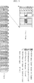
FIG. 4 is a schematic diagram illustrating a frame structure of an LTE system. -
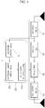
FIG. 5 is a functional block diagram illustrating a repeater including an apparatus for regulating transmission power of the repeater in an LTE system according to one embodiment of the present invention. -
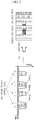
FIG. 6 is a schematic diagram illustrating detection of a timing of a sink signal through a sink signal detector according to one embodiment of the present invention. -
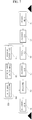
FIG. 7 is a schematic diagram illustrating an LTE system that supports a scalable bandwidth. -
FIG. 8 is a functional block diagram illustrating a repeater including an apparatus for regulating transmission power of the repeater in an LTE system according to another embodiment of the present invention. -
FIG. 9 is a functional block diagram illustrating a repeater including an apparatus for regulating transmission power of the repeater in an LTE system according to still another embodiment of the present invention. - Hereinafter, embodiments of the present invention will be described in detail with reference to the accompanying drawings.
- First, since an apparatus for regulating transmission power of a repeater according to one embodiment of the present invention is applied to an LTE system, the LTE system will be described hereinafter with reference to
FIG. 4 . -
FIG. 4 is a schematic diagram illustrating a frame structure of an LTE system. - One frame of the LTE system includes one or more subframes, as illustrated in
FIG. 4 . Further, the subframe includes at least one of a primary synchronization signal (PSS), a secondary synchronization signal (SSS), a physical broadcast channel (PBCH), a physical downlink control channel (PDCCH), and a reference signal. - The apparatus for regulating transmission power of a repeater according to one embodiment of the present invention regulates the transmission power of the repeater using a signal for which transmission power from a base station is constant, such as a reference signal existing in an LTE signal.
- Specifically, the apparatus for regulating transmission power of a repeater according to one embodiment of the present invention regulates the transmission power of the repeater using the PSS or the SSS which repeatedly appears every 5 msec in the frame of the LTE signal.
- Next, an apparatus that regulates the transmission power of the repeater according to one embodiment of the present invention will be described with reference to
FIGS. 5 and6 . -
FIG. 5 is a functional block diagram illustrating a repeater including an apparatus for regulating transmission power of the repeater in an LTE system according to one embodiment of the present invention, andFIG. 6 is a schematic diagram illustrating detection of a timing of a sink signal through a sink signal detector according to an embodiment of the present invention. - A
repeater 1 that receives a signal from a base station and retransmits the signal to a terminal includes an IF/RF receiver 10, anFA filter 30, anamplifier 50, an IF/RF transmitter 70, and anapparatus 100 for regulating the transmission power of the repeater, as illustrated inFIG. 5 . - Further, the
apparatus 100 for regulating transmission power of a repeater in an LTE system according to one embodiment of the present invention includes asink signal detector 110, a sinksignal power measurer 130, and anamplification controller 150. - The
sink signal detector 110 detects a sink signal of a reception signal (an analog signal or a digital signal) received from a base station (not illustrated) through the IF/RF receiver 10 of therepeater 1. Specifically, thesink signal detector 110 may detect the sink signal by causing the reception signal to pass through a low pass filter (LPF) having a predetermined bandwidth. Further, the sink signal may be detected by detecting a timing of the sink signal passing through the low pass filter. - The
repeater 1 receives the signal transmitted from the base station via the IF/RF receiver 10, and the received signal is transmitted to thesink signal detector 110. Thesink signal detector 110 performs filtering by causing the reception signal to pass through a low pass filter (LPF) having a bandwidth of the sink signal to be detected, as illustrated inFIG. 6 . - The signal obtained through the filtering indicates power according to time of the sink signal, as illustrated in
FIG. 6 . Here, the power of the sink signal according to the time may be the sink signal to be detected. - Further, the
sink signal detector 110 may detect a timing of each sink signal. InFIG. 6 , the respective sink signals appear at intervals of 5 msec. - Further, the respective sink signals to be detected are the PSS and the SSS described with reference to
FIG. 4 . - Further, the
sink signal detector 110 detects the sink signal by detecting the timing of the sink signal output from the low pass filter. Thesink signal detector 110 can detect a desired sink signal only by detecting a rough timing of the sink signal (i.e., roughly estimates the timing of the sink signal). - Further, the sink
signal power measurer 130 measures a size of the power of the sink signal detected through thesink signal detector 110. In other words, the sinksignal power measurer 130 obtains a moving average and measures average power for a portion corresponding to the timing of the sink signal detected through thesink signal detector 110. A size of the average power measured in this way indicates a size of average power of the signal received through the IF/RF receiver 10 of therepeater 1. - Further, the
amplification controller 150 calculates a gain of theamplifier 50 of therepeater 1 for maintaining the constant coverage of therepeater 1 based on the size of the (average) power of the sink signal measured through the sinksignal power measurer 130, and controls theamplifier 50 of therepeater 1 according to the calculated gain. - Here, the gain of the
amplifier 50 is determined by the following equation.
- GRepeater: The gain of the amplifier, PT: Target power, and PMA: The average power of the received signal
- Further, the
apparatus 100 for regulating transmission power of a repeater in an LTE system according to one embodiment of the present invention is also applicable to an LTE system that supports a scalable bandwidth. - The LTE system is standardized to be able to support various bandwidths within a standard. However, even in an LTE system having a different signal bandwidth, the sink signal maintains a predetermined bandwidth in the same position. Therefore, the
apparatus 100 for regulating transmission power of a repeater according to one embodiment of the present invention can regulate the transmission power of the repeater regardless of the bandwidth of the LTE system. - The
apparatus 100 for regulating transmission power of a repeater using the PSS, the SSS, or the BCH is also applicable to an LTE signal having various bandwidths, as illustrated inFIG. 7. FIG. 7 is a schematic diagram illustrating an LTE system that supports a scalable bandwidth. - Further, the
apparatus 100 for regulating transmission power of a repeater according to an embodiment of the present invention is also applicable to a digitally converted signal as illustrated inFIG. 8 , unlike that illustrated inFIG. 5 . - In other words, a
repeater 1 according to another embodiment of the present invention further includes an A/D converter 20 and a D/A converter 40. A signal of a base station received through an IF/RF receiver 10 of therepeater 1 is converted to a digital signal through the A/D converter and then transferred to asink signal detector 110.FIG. 8 is a functional block diagram illustrating a repeater including an apparatus for regulating transmission power of the repeater in an LTE system according to another embodiment of the present invention. - Finally, an
apparatus 100 for regulating transmission power of a repeater according to still another embodiment of the present invention will be described with reference toFIG. 9 . -
FIG. 9 is a functional block diagram illustrating a repeater including an apparatus for regulating transmission power of the repeater in an LTE system according to still another embodiment of the present invention. - An
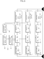
apparatus 100 for regulating transmission power of a repeater in an LTE system according to still another embodiment of the present invention can detect a sink signal for each of multiple LTE signals adjacent or separate in a frequency domain, measure power, and control a gain of each amplifier. In other words, theapparatus 100 for regulating transmission power of a repeater in an LTE system according to still another embodiment of the present invention can maintain coverage of therepeater 1 in a predetermined range by regulating an independent amplification gain for each of the multiple LTE signals. - The LTE signal includes one or more signals, and the
repeater 1 includes one or more IF/RF receivers 10-1, 10-2, and 10-3 that receive one or more LTE signals, FA filters 30-1, 30-2, and 30-3, amplifiers 50-1, 50-2, and 50-3, and IF/RF transmitters 70-1, 70-2, and 70-3, as illustrated inFIG. 9 . - Further, a
sink signal detector 110 of theapparatus 100 for regulating transmission power of a repeater in an LTE system according to still another embodiment of the present invention receives a signal from each of the one or more IF/RF receivers 10-1, 10-2, and 10-3. - Further, a sink
signal power measurer 130 measures a size of power of the sink signal detected through thesink signal detector 110 and transfers the power size to anamplification controller 150. - Further, the
amplification controller 150 performs control so that each of the one or more amplifiers 50-1, 50-2, and 50-3 amplifies a signal with a predetermined amplification gain.
Claims (7)
- An apparatus (100) for regulating transmission power of a repeater in an LTE - LONG TERM EVOLUTION - system, the apparatus comprising:a synchronization signal detector (110) that detects a synchronization signal of a reception signal received through an IF/RF receiver (10) of the repeater;a synchronization signal power measurer (130) that measures a size of power of the synchronization signal detected through the synchronization signal detector (110) ; andan amplification controller (150) that calculates a gain of an amplifier (50) of the repeater for maintaining coverage of the repeater based on the size of the power of the synchronization signal measured through the synchronization signal power measurer (130), and controls the amplifier of the repeater according to the calculated gain,wherein the repeater is provided to be electrically connected to the synchronization signal detector (110), the synchronization signal power measurer (130), the amplification controller (150), and the amplifier (50), andthe synchronization signal detector (110) detects the synchronization signal by causing the reception signal received through the IF/RF receiver (10) to pass through a low pass filter (LPF) having a bandwidth of the synchronization signal and estimating a timing of the synchronization signal from the passing signal.
- The apparatus according to claim 1, wherein:the synchronization signal detector (110) detects the synchronization signal through timing estimation of a primary synchronization signal -PSS-or a secondary synchronization signal -SSS- included in the synchronization signal.
- The apparatus according to claim 2, wherein:the PSS or the SSS of the synchronization signal detector (110) repeatedly appears every predetermined time in one frame of an LTE signal that is the reception signal.
- The apparatus according to claim 1, wherein:the synchronization signal power measurer (130) obtains average power of a timing part of the synchronization signal passing through the low pass filter -LPF-and calculates a size of the obtained average power as the size of the power of the synchronization signal.
- The apparatus according to claim 4, wherein the amplification controller (150) regulates the gain of the amplifier (50) based on the calculated power size of the synchronization signal and a predetermined target power determining the coverage of the repeater.
- The apparatus according to claim 1, wherein the reception signal received by the synchronization signal detector (110) is a signal obtained by converting the reception signal received through the IF/RF receiver (10) of the repeater to a digital signal.
- The apparatus according to claim 3, wherein:the LTE signal includes one or more signals,the synchronization signal detector receives all of respective signals of one or more IF/RF receivers (10-1, 10-2, 10-3) of the repeater included to receive the one or more LTE signals, andthe amplification controller (150) controls respective amplifiers (50-1, 50-2, 50-3) included to correspond to the number of the LTE signals.
Applications Claiming Priority (2)
| Application Number | Priority Date | Filing Date | Title |
|---|---|---|---|
| KR1020110127594A KR101243333B1 (en) | 2011-12-01 | 2011-12-01 | Apparatus for regulating trnasmission power of repeater in long term evolution system |
| PCT/KR2012/010272 WO2013081403A1 (en) | 2011-12-01 | 2012-11-30 | Apparatus for regulating transmission power of repeater in long term evolution system |
Publications (3)
| Publication Number | Publication Date |
|---|---|
| EP2787779A1 EP2787779A1 (en) | 2014-10-08 |
| EP2787779A4 EP2787779A4 (en) | 2015-07-01 |
| EP2787779B1 true EP2787779B1 (en) | 2018-04-18 |
Family
ID=48181832
Family Applications (1)
| Application Number | Title | Priority Date | Filing Date |
|---|---|---|---|
| EP12854057.2A Active EP2787779B1 (en) | 2011-12-01 | 2012-11-30 | Apparatus for regulating transmission power of repeater in long term evolution system |
Country Status (5)
| Country | Link |
|---|---|
| US (1) | US9231689B2 (en) |
| EP (1) | EP2787779B1 (en) |
| JP (1) | JP5852263B2 (en) |
| KR (1) | KR101243333B1 (en) |
| WO (1) | WO2013081403A1 (en) |
Families Citing this family (7)
| Publication number | Priority date | Publication date | Assignee | Title |
|---|---|---|---|---|
| KR101791635B1 (en) * | 2014-12-22 | 2017-10-30 | 주식회사 쏠리드 | Multi-band repeater having frequency selective gain control function |
| KR101825417B1 (en) * | 2014-12-30 | 2018-02-06 | 주식회사 쏠리드 | Interference cancellation repeater |
| KR101825416B1 (en) * | 2014-12-30 | 2018-03-22 | 주식회사 쏠리드 | Interference cancellation repeater |
| KR102006916B1 (en) * | 2015-12-31 | 2019-10-08 | 주식회사 쏠리드 | Repeater and method for attenuating a signal |
| KR102129063B1 (en) * | 2015-12-31 | 2020-07-01 | 주식회사 쏠리드 | Repeater and method for attenuating a signal |
| KR102153434B1 (en) * | 2019-07-09 | 2020-09-21 | 에스케이텔레콤 주식회사 | Apparatus for setting gain of a wireless repeater using a synchronous signal and method for the same |
| EP3863191B1 (en) | 2020-02-04 | 2025-11-05 | Nokia Solutions and Networks Oy | Communication system |
Family Cites Families (8)
| Publication number | Priority date | Publication date | Assignee | Title |
|---|---|---|---|---|
| US5583648A (en) * | 1993-04-07 | 1996-12-10 | Victor Company Of Japan, Ltd. | Picture signal recording/reproducing method and apparatus for recording/reproducing a high-definition picture signal and a normal picture signal |
| KR100924982B1 (en) | 2005-01-20 | 2009-11-04 | 주식회사 엠투테크 | Repeater with coverage adjustment by pilot signal tracking |
| JP2007028511A (en) | 2005-07-21 | 2007-02-01 | Sony Corp | Wireless communication apparatus, wireless communication method, and program thereof |
| KR20090063853A (en) | 2007-12-14 | 2009-06-18 | 주식회사 엠티아이 | Repeater Reverse Gain Control System, and Method |
| EP2323299A4 (en) | 2008-08-27 | 2013-11-06 | Ntt Docomo Inc | MOBILE STATION AND MOBILE COMMUNICATION METHOD |
| JP4887413B2 (en) | 2009-09-24 | 2012-02-29 | 東芝デジタルメディアエンジニアリング株式会社 | Non-regenerative wireless relay device and wireless relay system |
| KR101298590B1 (en) * | 2009-12-21 | 2013-08-26 | 한국전자통신연구원 | Apparatus and method of repeating in wireless communication systems |
| US9094083B2 (en) * | 2010-05-18 | 2015-07-28 | Qualcomm Incorporated | Systems, apparatus and methods to facilitate efficient repeater usage |
-
2011
- 2011-12-01 KR KR1020110127594A patent/KR101243333B1/en active Active
-
2012
- 2012-11-30 JP JP2014544669A patent/JP5852263B2/en active Active
- 2012-11-30 EP EP12854057.2A patent/EP2787779B1/en active Active
- 2012-11-30 WO PCT/KR2012/010272 patent/WO2013081403A1/en not_active Ceased
- 2012-11-30 US US14/362,391 patent/US9231689B2/en active Active
Non-Patent Citations (1)
| Title |
|---|
| None * |
Also Published As
| Publication number | Publication date |
|---|---|
| EP2787779A4 (en) | 2015-07-01 |
| US20140335779A1 (en) | 2014-11-13 |
| US9231689B2 (en) | 2016-01-05 |
| JP5852263B2 (en) | 2016-02-03 |
| WO2013081403A1 (en) | 2013-06-06 |
| KR101243333B1 (en) | 2013-03-13 |
| EP2787779A1 (en) | 2014-10-08 |
| JP2015500586A (en) | 2015-01-05 |
Similar Documents
| Publication | Publication Date | Title |
|---|---|---|
| EP2787779A1 (en) | Apparatus for regulating transmission power of repeater in long term evolution system | |
| JP7289189B2 (en) | Terminal device, location server and method | |
| US8248997B2 (en) | Apparatus and method for positioning a wireless user equipment | |
| US11726163B2 (en) | Position detection of user equipment within a wireless telecommunication network | |
| CN110071791B (en) | Switching subsystem for distributed antenna system utilizing time division duplexing | |
| CN109997404B (en) | Random Access Method for Multiple Parameter Set Operation | |
| EP2319203B1 (en) | Method and apparatus for determining an end of a subframe in a tdd system | |
| EP3254135B1 (en) | Locating the source of a wireless signal | |
| KR101931849B1 (en) | Radio network node, user equipment and methods therein | |
| EP3108600B1 (en) | A self-optimizing network entity for a telecommunications system | |
| EP3193465A2 (en) | Configuration sub-system for telecommunication systems | |
| EP4044663A1 (en) | Method and apparatus for transmitting channel state information | |
| EP1903695A3 (en) | Mobile user terminal, mobile communication system, base station, and communication method | |
| EP2498436A2 (en) | Method and apparatus for transmitting and receiving control information in a wireless communication system | |
| US9844012B2 (en) | Automatic gain control gain adjustment | |
| EP2209250B1 (en) | Pilot arrangement for mobile radio communication systems | |
| JP5364537B2 (en) | Radio relay apparatus and radio relay method | |
| US20130003644A1 (en) | Mobile communication method, mobile station, and relay node | |
| US10006984B2 (en) | Method, apparatuses and system for improved wireless device location in shared cells | |
| US9537517B2 (en) | Method of controlling uplink noise level in multi-RU environment | |
| US20180034533A1 (en) | Interference cancellation repeater | |
| KR101741355B1 (en) | Apparatus and method for extending coverage in lte communication system | |
| KR101115516B1 (en) | Transmitter of wireless communication system and power control method thereof | |
| JP2012249319A (en) | Pilot arrangement method for mobile radio communication system, and transceiver device applying the same | |
| JP2016015605A (en) | Radio communication device |
Legal Events
| Date | Code | Title | Description |
|---|---|---|---|
| PUAI | Public reference made under article 153(3) epc to a published international application that has entered the european phase |
Free format text: ORIGINAL CODE: 0009012 |
|
| 17P | Request for examination filed |
Effective date: 20140701 |
|
| AK | Designated contracting states |
Kind code of ref document: A1 Designated state(s): AL AT BE BG CH CY CZ DE DK EE ES FI FR GB GR HR HU IE IS IT LI LT LU LV MC MK MT NL NO PL PT RO RS SE SI SK SM TR |
|
| DAX | Request for extension of the european patent (deleted) | ||
| RA4 | Supplementary search report drawn up and despatched (corrected) |
Effective date: 20150603 |
|
| RIC1 | Information provided on ipc code assigned before grant |
Ipc: H04W 52/46 20090101AFI20150528BHEP Ipc: H04J 11/00 20060101ALI20150528BHEP Ipc: H04W 52/18 20090101ALI20150528BHEP Ipc: H04B 7/14 20060101ALI20150528BHEP Ipc: H04W 52/52 20090101ALI20150528BHEP Ipc: H04W 52/14 20090101ALN20150528BHEP Ipc: H04W 52/24 20090101ALN20150528BHEP |
|
| REG | Reference to a national code |
Ref country code: DE Ref legal event code: R079 Ref document number: 602012045459 Country of ref document: DE Free format text: PREVIOUS MAIN CLASS: H04W0052180000 Ipc: H04W0052460000 |
|
| GRAP | Despatch of communication of intention to grant a patent |
Free format text: ORIGINAL CODE: EPIDOSNIGR1 |
|
| RIC1 | Information provided on ipc code assigned before grant |
Ipc: H04W 52/52 20090101ALI20171101BHEP Ipc: H04J 11/00 20060101ALI20171101BHEP Ipc: H04W 52/14 20090101ALN20171101BHEP Ipc: H04W 52/18 20090101ALI20171101BHEP Ipc: H04B 7/14 20060101ALI20171101BHEP Ipc: H04W 52/24 20090101ALN20171101BHEP Ipc: H04W 52/46 20090101AFI20171101BHEP |
|
| RAP1 | Party data changed (applicant data changed or rights of an application transferred) |
Owner name: SOLID TECHNOLOGIES INC. |
|
| INTG | Intention to grant announced |
Effective date: 20171120 |
|
| GRAS | Grant fee paid |
Free format text: ORIGINAL CODE: EPIDOSNIGR3 |
|
| GRAA | (expected) grant |
Free format text: ORIGINAL CODE: 0009210 |
|
| AK | Designated contracting states |
Kind code of ref document: B1 Designated state(s): AL AT BE BG CH CY CZ DE DK EE ES FI FR GB GR HR HU IE IS IT LI LT LU LV MC MK MT NL NO PL PT RO RS SE SI SK SM TR |
|
| REG | Reference to a national code |
Ref country code: GB Ref legal event code: FG4D |
|
| REG | Reference to a national code |
Ref country code: CH Ref legal event code: EP |
|
| REG | Reference to a national code |
Ref country code: AT Ref legal event code: REF Ref document number: 991752 Country of ref document: AT Kind code of ref document: T Effective date: 20180515 |
|
| REG | Reference to a national code |
Ref country code: IE Ref legal event code: FG4D |
|
| REG | Reference to a national code |
Ref country code: DE Ref legal event code: R096 Ref document number: 602012045459 Country of ref document: DE |
|
| REG | Reference to a national code |
Ref country code: NL Ref legal event code: MP Effective date: 20180418 |
|
| REG | Reference to a national code |
Ref country code: LT Ref legal event code: MG4D |
|
| PG25 | Lapsed in a contracting state [announced via postgrant information from national office to epo] |
Ref country code: NL Free format text: LAPSE BECAUSE OF FAILURE TO SUBMIT A TRANSLATION OF THE DESCRIPTION OR TO PAY THE FEE WITHIN THE PRESCRIBED TIME-LIMIT Effective date: 20180418 |
|
| PG25 | Lapsed in a contracting state [announced via postgrant information from national office to epo] |
Ref country code: ES Free format text: LAPSE BECAUSE OF FAILURE TO SUBMIT A TRANSLATION OF THE DESCRIPTION OR TO PAY THE FEE WITHIN THE PRESCRIBED TIME-LIMIT Effective date: 20180418 Ref country code: AL Free format text: LAPSE BECAUSE OF FAILURE TO SUBMIT A TRANSLATION OF THE DESCRIPTION OR TO PAY THE FEE WITHIN THE PRESCRIBED TIME-LIMIT Effective date: 20180418 Ref country code: BG Free format text: LAPSE BECAUSE OF FAILURE TO SUBMIT A TRANSLATION OF THE DESCRIPTION OR TO PAY THE FEE WITHIN THE PRESCRIBED TIME-LIMIT Effective date: 20180718 Ref country code: LT Free format text: LAPSE BECAUSE OF FAILURE TO SUBMIT A TRANSLATION OF THE DESCRIPTION OR TO PAY THE FEE WITHIN THE PRESCRIBED TIME-LIMIT Effective date: 20180418 Ref country code: NO Free format text: LAPSE BECAUSE OF FAILURE TO SUBMIT A TRANSLATION OF THE DESCRIPTION OR TO PAY THE FEE WITHIN THE PRESCRIBED TIME-LIMIT Effective date: 20180718 Ref country code: FI Free format text: LAPSE BECAUSE OF FAILURE TO SUBMIT A TRANSLATION OF THE DESCRIPTION OR TO PAY THE FEE WITHIN THE PRESCRIBED TIME-LIMIT Effective date: 20180418 Ref country code: SE Free format text: LAPSE BECAUSE OF FAILURE TO SUBMIT A TRANSLATION OF THE DESCRIPTION OR TO PAY THE FEE WITHIN THE PRESCRIBED TIME-LIMIT Effective date: 20180418 Ref country code: PL Free format text: LAPSE BECAUSE OF FAILURE TO SUBMIT A TRANSLATION OF THE DESCRIPTION OR TO PAY THE FEE WITHIN THE PRESCRIBED TIME-LIMIT Effective date: 20180418 |
|
| PG25 | Lapsed in a contracting state [announced via postgrant information from national office to epo] |
Ref country code: LV Free format text: LAPSE BECAUSE OF FAILURE TO SUBMIT A TRANSLATION OF THE DESCRIPTION OR TO PAY THE FEE WITHIN THE PRESCRIBED TIME-LIMIT Effective date: 20180418 Ref country code: HR Free format text: LAPSE BECAUSE OF FAILURE TO SUBMIT A TRANSLATION OF THE DESCRIPTION OR TO PAY THE FEE WITHIN THE PRESCRIBED TIME-LIMIT Effective date: 20180418 Ref country code: GR Free format text: LAPSE BECAUSE OF FAILURE TO SUBMIT A TRANSLATION OF THE DESCRIPTION OR TO PAY THE FEE WITHIN THE PRESCRIBED TIME-LIMIT Effective date: 20180719 Ref country code: RS Free format text: LAPSE BECAUSE OF FAILURE TO SUBMIT A TRANSLATION OF THE DESCRIPTION OR TO PAY THE FEE WITHIN THE PRESCRIBED TIME-LIMIT Effective date: 20180418 |
|
| REG | Reference to a national code |
Ref country code: AT Ref legal event code: MK05 Ref document number: 991752 Country of ref document: AT Kind code of ref document: T Effective date: 20180418 |
|
| PG25 | Lapsed in a contracting state [announced via postgrant information from national office to epo] |
Ref country code: PT Free format text: LAPSE BECAUSE OF FAILURE TO SUBMIT A TRANSLATION OF THE DESCRIPTION OR TO PAY THE FEE WITHIN THE PRESCRIBED TIME-LIMIT Effective date: 20180820 |
|
| REG | Reference to a national code |
Ref country code: DE Ref legal event code: R097 Ref document number: 602012045459 Country of ref document: DE |
|
| PG25 | Lapsed in a contracting state [announced via postgrant information from national office to epo] |
Ref country code: CZ Free format text: LAPSE BECAUSE OF FAILURE TO SUBMIT A TRANSLATION OF THE DESCRIPTION OR TO PAY THE FEE WITHIN THE PRESCRIBED TIME-LIMIT Effective date: 20180418 Ref country code: SK Free format text: LAPSE BECAUSE OF FAILURE TO SUBMIT A TRANSLATION OF THE DESCRIPTION OR TO PAY THE FEE WITHIN THE PRESCRIBED TIME-LIMIT Effective date: 20180418 Ref country code: RO Free format text: LAPSE BECAUSE OF FAILURE TO SUBMIT A TRANSLATION OF THE DESCRIPTION OR TO PAY THE FEE WITHIN THE PRESCRIBED TIME-LIMIT Effective date: 20180418 Ref country code: AT Free format text: LAPSE BECAUSE OF FAILURE TO SUBMIT A TRANSLATION OF THE DESCRIPTION OR TO PAY THE FEE WITHIN THE PRESCRIBED TIME-LIMIT Effective date: 20180418 Ref country code: DK Free format text: LAPSE BECAUSE OF FAILURE TO SUBMIT A TRANSLATION OF THE DESCRIPTION OR TO PAY THE FEE WITHIN THE PRESCRIBED TIME-LIMIT Effective date: 20180418 Ref country code: EE Free format text: LAPSE BECAUSE OF FAILURE TO SUBMIT A TRANSLATION OF THE DESCRIPTION OR TO PAY THE FEE WITHIN THE PRESCRIBED TIME-LIMIT Effective date: 20180418 |
|
| PLBE | No opposition filed within time limit |
Free format text: ORIGINAL CODE: 0009261 |
|
| STAA | Information on the status of an ep patent application or granted ep patent |
Free format text: STATUS: NO OPPOSITION FILED WITHIN TIME LIMIT |
|
| PG25 | Lapsed in a contracting state [announced via postgrant information from national office to epo] |
Ref country code: IT Free format text: LAPSE BECAUSE OF FAILURE TO SUBMIT A TRANSLATION OF THE DESCRIPTION OR TO PAY THE FEE WITHIN THE PRESCRIBED TIME-LIMIT Effective date: 20180418 Ref country code: SM Free format text: LAPSE BECAUSE OF FAILURE TO SUBMIT A TRANSLATION OF THE DESCRIPTION OR TO PAY THE FEE WITHIN THE PRESCRIBED TIME-LIMIT Effective date: 20180418 |
|
| 26N | No opposition filed |
Effective date: 20190121 |
|
| PG25 | Lapsed in a contracting state [announced via postgrant information from national office to epo] |
Ref country code: SI Free format text: LAPSE BECAUSE OF FAILURE TO SUBMIT A TRANSLATION OF THE DESCRIPTION OR TO PAY THE FEE WITHIN THE PRESCRIBED TIME-LIMIT Effective date: 20180418 |
|
| REG | Reference to a national code |
Ref country code: CH Ref legal event code: PL |
|
| PG25 | Lapsed in a contracting state [announced via postgrant information from national office to epo] |
Ref country code: MC Free format text: LAPSE BECAUSE OF FAILURE TO SUBMIT A TRANSLATION OF THE DESCRIPTION OR TO PAY THE FEE WITHIN THE PRESCRIBED TIME-LIMIT Effective date: 20180418 Ref country code: LU Free format text: LAPSE BECAUSE OF NON-PAYMENT OF DUE FEES Effective date: 20181130 |
|
| REG | Reference to a national code |
Ref country code: BE Ref legal event code: MM Effective date: 20181130 |
|
| REG | Reference to a national code |
Ref country code: IE Ref legal event code: MM4A |
|
| PG25 | Lapsed in a contracting state [announced via postgrant information from national office to epo] |
Ref country code: LI Free format text: LAPSE BECAUSE OF NON-PAYMENT OF DUE FEES Effective date: 20181130 Ref country code: CH Free format text: LAPSE BECAUSE OF NON-PAYMENT OF DUE FEES Effective date: 20181130 |
|
| PG25 | Lapsed in a contracting state [announced via postgrant information from national office to epo] |
Ref country code: IE Free format text: LAPSE BECAUSE OF NON-PAYMENT OF DUE FEES Effective date: 20181130 |
|
| PG25 | Lapsed in a contracting state [announced via postgrant information from national office to epo] |
Ref country code: BE Free format text: LAPSE BECAUSE OF NON-PAYMENT OF DUE FEES Effective date: 20181130 |
|
| PG25 | Lapsed in a contracting state [announced via postgrant information from national office to epo] |
Ref country code: MT Free format text: LAPSE BECAUSE OF NON-PAYMENT OF DUE FEES Effective date: 20181130 |
|
| PG25 | Lapsed in a contracting state [announced via postgrant information from national office to epo] |
Ref country code: TR Free format text: LAPSE BECAUSE OF FAILURE TO SUBMIT A TRANSLATION OF THE DESCRIPTION OR TO PAY THE FEE WITHIN THE PRESCRIBED TIME-LIMIT Effective date: 20180418 |
|
| PG25 | Lapsed in a contracting state [announced via postgrant information from national office to epo] |
Ref country code: HU Free format text: LAPSE BECAUSE OF FAILURE TO SUBMIT A TRANSLATION OF THE DESCRIPTION OR TO PAY THE FEE WITHIN THE PRESCRIBED TIME-LIMIT; INVALID AB INITIO Effective date: 20121130 Ref country code: CY Free format text: LAPSE BECAUSE OF FAILURE TO SUBMIT A TRANSLATION OF THE DESCRIPTION OR TO PAY THE FEE WITHIN THE PRESCRIBED TIME-LIMIT Effective date: 20180418 Ref country code: MK Free format text: LAPSE BECAUSE OF NON-PAYMENT OF DUE FEES Effective date: 20180418 |
|
| PG25 | Lapsed in a contracting state [announced via postgrant information from national office to epo] |
Ref country code: IS Free format text: LAPSE BECAUSE OF FAILURE TO SUBMIT A TRANSLATION OF THE DESCRIPTION OR TO PAY THE FEE WITHIN THE PRESCRIBED TIME-LIMIT Effective date: 20180818 |
|
| PGFP | Annual fee paid to national office [announced via postgrant information from national office to epo] |
Ref country code: DE Payment date: 20251118 Year of fee payment: 14 |
|
| PGFP | Annual fee paid to national office [announced via postgrant information from national office to epo] |
Ref country code: GB Payment date: 20251120 Year of fee payment: 14 |
|
| PGFP | Annual fee paid to national office [announced via postgrant information from national office to epo] |
Ref country code: FR Payment date: 20251125 Year of fee payment: 14 |