EP2787719A1 - Method and apparatus for generating multi-bit deep halftone amplitude modulation dot - Google Patents
Method and apparatus for generating multi-bit deep halftone amplitude modulation dot Download PDFInfo
- Publication number
- EP2787719A1 EP2787719A1 EP12853124.1A EP12853124A EP2787719A1 EP 2787719 A1 EP2787719 A1 EP 2787719A1 EP 12853124 A EP12853124 A EP 12853124A EP 2787719 A1 EP2787719 A1 EP 2787719A1
- Authority
- EP
- European Patent Office
- Prior art keywords
- line
- value
- matrix
- bit depth
- setting
- Prior art date
- Legal status (The legal status is an assumption and is not a legal conclusion. Google has not performed a legal analysis and makes no representation as to the accuracy of the status listed.)
- Ceased
Links
Images


Classifications
-
- H—ELECTRICITY
- H04—ELECTRIC COMMUNICATION TECHNIQUE
- H04N—PICTORIAL COMMUNICATION, e.g. TELEVISION
- H04N1/00—Scanning, transmission or reproduction of documents or the like, e.g. facsimile transmission; Details thereof
- H04N1/40—Picture signal circuits
- H04N1/40087—Multi-toning, i.e. converting a continuous-tone signal for reproduction with more than two discrete brightnesses or optical densities, e.g. dots of grey and black inks on white paper
-
- G—PHYSICS
- G06—COMPUTING OR CALCULATING; COUNTING
- G06K—GRAPHICAL DATA READING; PRESENTATION OF DATA; RECORD CARRIERS; HANDLING RECORD CARRIERS
- G06K15/00—Arrangements for producing a permanent visual presentation of the output data, e.g. computer output printers
- G06K15/02—Arrangements for producing a permanent visual presentation of the output data, e.g. computer output printers using printers
- G06K15/18—Conditioning data for presenting it to the physical printing elements
- G06K15/1867—Post-processing of the composed and rasterized print image
- G06K15/1872—Image enhancement
- G06K15/1881—Halftoning
-
- H—ELECTRICITY
- H04—ELECTRIC COMMUNICATION TECHNIQUE
- H04N—PICTORIAL COMMUNICATION, e.g. TELEVISION
- H04N1/00—Scanning, transmission or reproduction of documents or the like, e.g. facsimile transmission; Details thereof
- H04N1/40—Picture signal circuits
- H04N1/405—Halftoning, i.e. converting the picture signal of a continuous-tone original into a corresponding signal showing only two levels
- H04N1/4055—Halftoning, i.e. converting the picture signal of a continuous-tone original into a corresponding signal showing only two levels producing a clustered dots or a size modulated halftone pattern
Definitions
- the present application relates to a technical field of printing, in particular, to a method and an apparatus for generating multi-bit depth halftone amplitude-modulation dots.
- the hard copying for image duplication generally relates to the screening and plate-making technology for printers and the advanced printing and plate-making device.
- the screening technology used for duplicating an image with hard copying is also called the digital image halftone technology.
- the digital image halftone technology comprises amplitude-modulation (AM) screening and frequency-modulation (FM) screening.
- AM amplitude-modulation
- FM frequency-modulation
- the amplitude-modulation screening technique is also called ordered dithering of gathered dots, characterizing in that, the colored points in a produced halftone image are gathered in pairs geometrically to form clusters of colored regions, which are called dots. Since the technology controls the size of the dots to represent the gray level of the original image, the dots are called amplitude-modulation dots.
- the output gradations of the apparatus increase up to the power of 2 depending on the imaging depth.
- the general 2-bit or 4-bit output apparatus can represent 4 or 16 gradations, respectively.
- the final object of the multi-bit depth imaging apparatus is to obtain the output effect with high resolution under low resolution so as to overcome the problem of imaging quality under low resolution.
- PWM Pulse Width Modification
- the amplitude-modulation dot with one-bit depth is usually used in the conventional halftone screening process. Therefore, it is important for improving the high-quality amplitude-modulation effect of the multi-bit depth apparatus that how to transfer an one-bit amplitude-modulation dot data to the multi-bit amplitude-modulation dots associated with the characteristics of the apparatus, how to make full use of existing characteristics of the apparatus, and to obtain the output effect with high resolution under low resolution.
- image zoom technology is usually applied to achieve the multi-bit depth amplitude-modulation.
- the image zooming technology first the original one-bit depth amplitude-modulation dot data may be expanded to one-bit dot with a high resolution. Then the one-bit dot with a high resolution may be transferred to lattice data with a lower resolution supported by the current apparatus through the image zooming technology. Meanwhile, dot gradation required by the bit depth of the apparatus may be defined so as to achieve the multi-bit depth dots effect.
- the present application intents to provide a method and an apparatus for generating multi-bit depth halftone amplitude-modulation dots to solve the problem of a bad timeliness.
- L represents the number of a frequency-modulation screen gradation
- L 2 e
- e represents a bit depth value of the printer
- i is an integer and i ⁇ [0 ,L -1]
- g j is the element value of the i th line and j th row in G .
- an apparatus for generating multi-bit depth halftone amplitude-modulation dots may comprise a scanning module, a generating module and a repeating module.
- the scanning module may be configured to scan an input image to obtain a value of a current pixel P xy , where x represents a lateral position index of the current pixel, and y represents a vertical position index of the current pixel.
- the repeating module may be configured to increase i and to invoke the generating module.
- L represents the number of a frequency-modulation screen gradation
- L 2 e
- e represents a bit depth value of the printer
- i is an integer and i ⁇ [0, L -1]
- g j is the element value of the i th line and j th row in G.
- the method and the apparatus for generating multi-bit depth halftone amplitude-modulation dots can solve the problem of a bad timeliness and improve the speed for generating the multi-bit depth halftone amplitude-modulation dots without transferring the dots data for many times.
- Fig. 1 is a flowchart illustrating a method for generating multi-bit depth halftone amplitude-modulation dots according to an embodiment of the present application. The method may include the following steps.
- Step S10 scanning an input image to obtain a value of a current pixel P xy , where x represents a lateral position index of the current pixel, and y represents a vertical position index of the current pixel.
- Step 320 increasing i and proceeding step S20 .
- L represents the number of a frequency-modulation screen gradation
- L 2 e , where e represents a bit depth value of the printer, i is an integer and i ⁇ [0, L -1].
- g j is the element value of the i th line and j th row in G.
- the dots data does not need to be transferred for many times, such that the problem of bad timeliness can be solved. Meanwhile, the speed for generating the multi-bit depth halftone dots can be improved.
- the transferred dots data in related technology belong to quasi multi-bit depth dots data, and there are too many pixels with high gray level in the center of the amplitude-modulation screen. This will result in a serious impact to subsequent color correction and saturation, and thus the transferred dots data in related technology are not real multi-bit amplitude-modulation screen to achieve a stable output quality and color quality.
- the threshold matrix screening controlling gradation which has the same number as the bit depth gradation of the apparatus can be used to achieve a stable output quality and color quality.
- the multi-bit depth threshold matrix G is preset to: Line 1 : g 1 , g 2 , g 3 , ... ... ... ... ... g n ⁇ m
- Line 2 : g n ⁇ m + 1 , g n ⁇ m + 2 , g n ⁇ m + 3 ... ... ... ... ... g 2 ⁇ n ⁇ m ⁇ Line i : ... ... ... ... g j
- Line i - 1 : g L - 2 ⁇ n ⁇ m + 1 , g L - 2 ⁇ n ⁇ m + 2 ⁇ ⁇ ⁇ ⁇ g L - 1 ⁇ n ⁇ m
- m represents a width of the matrix
- n represents a height of the matrix.
- the presetting step of the multi-bit depth threshold matrix G may include the following steps.
- Step 2) transferring logic are given as follows:
- the initial halftone one-bit amplitude-modulation screen threshold matrix T is preset to: t 11 , t 12 , t 13 , ... ... ... ... t 1 ⁇ m t 21 , t 22 , t 23 , ... ... ... ... t 2 ⁇ m ⁇ t xy ⁇ t n ⁇ 1 , t n ⁇ 2 , t n ⁇ 3 , ... ... ... ... t nm where t xy ⁇ [1, m ⁇ n ] and t xy in the matrix meets element anisotropy for each two.
- the permutation matrix A i is preset to: Line 0 : a 01 , a 02 , a 03 , ... ... ... ... a 0 ⁇ U 0 , Line 1 : a 11 , a 12 , a 13 , ... ... ... ... ... a 1 ⁇ U 1 - L + 1 , ⁇ Line i : a i ⁇ 1 , a i ⁇ 2 , a i ⁇ 3 , ... ... ... ... a xy , ... ... ... ... ... a i ⁇ U i , ⁇ Line L - 3 : a L - 3 ⁇ 1 , a L - 3 ⁇ 2 , a L - 3 ⁇ 3 , a L - 3 ⁇ 4 , Line L - 2 : a L - 2 ⁇ 1 , a L - 2 ⁇ 2 , a L - 2
- Fig. 2 the flowchart of the method for generating multi-bit depth halftone dots is shown in Fig. 2 .
- Fig. 3 is a flowchart illustrating a method for transferring a single threshold matrix to a multi-bit depth threshold matrix according to a preferable embodiment of the present application. The method may include the following steps.
- Step S102 providing the initial halftone one-bit amplitude-modulation screen threshold matrix T t 11 , t 12 , t 13 , ... ... ... ... t 1 ⁇ m t 21 , t 22 , t 23 , ... ... ... ... t 2 ⁇ m ⁇ t xy ⁇ t n ⁇ 1 , t n ⁇ 2 , t n ⁇ 3 , ... ... ... ... t nm
- t xy is corresponding to a single element in the matrix
- x and y represent indexes of a lateral and a vertical position, respectively
- m represents a width of the matrix
- the initial halftone one-bit amplitude-modulation screen threshold matrix T is known to one skilled in the art.
- the threshold matrix T description cover all related or similar data when it is taken as an input parameter of the process of the present application.
- L is set to 8
- the permutation matrix A i can be calculated to: 0 , 0 , 0 , 0 , 0 , 0 , 0 , 0 , 0 , 0 , 0 , 0 , 0 , 0 , 0 , 0 , 0 , 0 , 0 , 0 , 0 , 0 , 0 , 0 , 0 , 0 , 0 , 0 , 0 , 0 , 0 , 0 , 0 , 0 , 0 , 0 , 0 , 0 , 0 , 0 , 0 , 0 , 0 , 0 , 0 , 0 , 1 , 1 , 1 , 1 , 1 , 1 , 1 , 1 , 1 ,
- the threshold matrix T is transferred to multi-bit depth threshold matrix G through the permutation matrix A i , and the matrix G is set to Line 1 : g 1 , g 2 , g 3 , ... ... ... ... ... g n ⁇ m Line 2 : g n ⁇ m + 1 , g n ⁇ m + 2 , g n ⁇ m + 3 ... ... ... ... ... g 2 ⁇ n ⁇ m ⁇ Line i : ... ... ... ... g j Line i - 1 : g L - 2 ⁇ n ⁇ m + 1 , g L - 2 ⁇ n ⁇ m + 2 ⁇ ⁇ ⁇ ⁇ g L - 1 ⁇ n ⁇ m in which there are n ⁇ m elements in each line, and g j represent an element in i th line.
- Step S106 setting initial parameters as follows:
- Step S110 when a xy ⁇ ( L -1) and S a ⁇ ( m ⁇ n ) (condition 1), proceeding the following operations.
- Step S120 repeating the steps S108 to S118 until C > M (condition 3), and then ending the operations.
- Fig. 5 shows the flowchart of screening process, and the screening process may include the following steps.
- Step S202 scanning an input image to obtain a value of a current pixel P xy , where x represents a lateral position index of the current pixel, and y represents a vertical position index of the current pixel.
- Step S206 traversing the multi-bit depth threshold matrix G, and obtaining the threshold g j corresponding to the matrix G based on the index h.
- Step S208 comparing the screening threshold under the condition P xy ⁇ g j (condition 4).
- Step S212 determining whether all the pixels of the image are processed, if not, returning to the step S202, otherwise, ending the process.
- final halftone 3-bit dots are output through the above transferring and calculating steps.
- Fig. 6 shows a screening effect diagram.
- Fig. 7 is a schematic diagram illustrating an apparatus for generating multi-bit depth halftone amplitude-modulation dots according to an embodiment of the present application, and the apparatus may include a scanning module 10, a generating module 20 and a repeating module 30.
- the scanning module 10 may be configured to scan an input image to obtain a value of a current pixel P xy , where x represents a lateral position index of the current pixel, and y represents a vertical position index of the current pixel.
- the repeating module 30 may be configured to increase i and to invoke the generating module 20.
- L represents the number of a frequency-modulation screen gradation
- L 2 e
- e represents a bit depth value of the printer
- g j is the element value of the i th line and j th row in G
- i is an integer and i ⁇ [0, L -1].
- the characteristics of the multi-bit imaging apparatus can be used to their full potential according to requirements for dots.
- the output device with a multi-bit depth imaging depth can output a level full multi-bit halftone image with a high quality.
- the phenomenon of contour jaggies of the one-bit depth apparatus can be effectively resolved in order to output the amplitude-modulation dots with high resolution under low resolution.
- modules or steps of the present application may be implemented with a common computing device.
- the modules or steps of the present application can be concentrated or run in a single computing device or distributed in a network composed of multiple computing devices.
- the modules or steps may be achieved by using codes of the executable program, so that they can be stored in the storage medium, or the plurality of the modules or steps can be fabricated into an individual integrated circuit module. Therefore, the present application is not limited to any particular hardware, software or combination thereof.
Landscapes
- Engineering & Computer Science (AREA)
- Multimedia (AREA)
- Signal Processing (AREA)
- Physics & Mathematics (AREA)
- General Physics & Mathematics (AREA)
- Discrete Mathematics (AREA)
- General Engineering & Computer Science (AREA)
- Theoretical Computer Science (AREA)
- Facsimile Image Signal Circuits (AREA)
- Image Processing (AREA)
Abstract
Description
- The present application relates to a technical field of printing, in particular, to a method and an apparatus for generating multi-bit depth halftone amplitude-modulation dots.
- The hard copying for image duplication generally relates to the screening and plate-making technology for printers and the advanced printing and plate-making device. The screening technology used for duplicating an image with hard copying is also called the digital image halftone technology. The digital image halftone technology comprises amplitude-modulation (AM) screening and frequency-modulation (FM) screening. The amplitude-modulation screening technique is also called ordered dithering of gathered dots, characterizing in that, the colored points in a produced halftone image are gathered in pairs geometrically to form clusters of colored regions, which are called dots. Since the technology controls the size of the dots to represent the gray level of the original image, the dots are called amplitude-modulation dots.
- In the prior art there are some multi-bit depth imaging apparatus. The output gradations of the apparatus increase up to the power of 2 depending on the imaging depth. The general 2-bit or 4-bit output apparatus can represent 4 or 16 gradations, respectively. The final object of the multi-bit depth imaging apparatus is to obtain the output effect with high resolution under low resolution so as to overcome the problem of imaging quality under low resolution. Furthermore, in combination with the Pulse Width Modification (PWM) gradation offset technology embedded in the multi-bit depth imaging apparatus, the halftone dots are output stably and the optimized quality of the halftone dots output by the apparatus is obtained.
- In view of the characteristics of the multi-bit depth apparatus, new demands and challenges for different ways of halftone screening emerge. The amplitude-modulation dot with one-bit depth is usually used in the conventional halftone screening process. Therefore, it is important for improving the high-quality amplitude-modulation effect of the multi-bit depth apparatus that how to transfer an one-bit amplitude-modulation dot data to the multi-bit amplitude-modulation dots associated with the characteristics of the apparatus, how to make full use of existing characteristics of the apparatus, and to obtain the output effect with high resolution under low resolution.
- At present, image zoom technology is usually applied to achieve the multi-bit depth amplitude-modulation. With the image zooming technology, first the original one-bit depth amplitude-modulation dot data may be expanded to one-bit dot with a high resolution. Then the one-bit dot with a high resolution may be transferred to lattice data with a lower resolution supported by the current apparatus through the image zooming technology. Meanwhile, dot gradation required by the bit depth of the apparatus may be defined so as to achieve the multi-bit depth dots effect. However, it is required to transfer the dots data for many times and thus this method is too complicate to achieve and has a big problem of timeliness.
- The present application intents to provide a method and an apparatus for generating multi-bit depth halftone amplitude-modulation dots to solve the problem of a bad timeliness.
- According to one embodiment of the present application, a method for generating multi-bit depth halftone amplitude-modulation dots is provided. The method may comprise: scanning an input image to obtain a value of a current pixel Pxy, where x represents a lateral position index of the current pixel, and y represents a vertical position index of the current pixel; obtaining gj from a preset multi-bit depth threshold matrix G by starting with i=0, and determining if Pxy < gj, if yew, providing a screening output gray level gradation value of the printer to Out=L-1-i; otherwise, increasing i and repeating the determining and providing steps. L represents the number of a frequency-modulation screen gradation, L = 2 e , e represents a bit depth value of the printer, i is an integer and i∈[0,L-1], h is an index number of an element g arranged sequentially in G and h is provided to h = (y%n) × m + (x%m) + i × m × n, and gj is the element value of the ith line and jth row in G.
- According to another embodiment of the present application, an apparatus for generating multi-bit depth halftone amplitude-modulation dots is provided. The apparatus may comprise a scanning module, a generating module and a repeating module. The scanning module may be configured to scan an input image to obtain a value of a current pixel Pxy, where x represents a lateral position index of the current pixel, and y represents a vertical position index of the current pixel. The
generating module 20 may be configured to obtain gj from a preset multi-bit depth threshold matrix G by starting with i=0. If Pxy < gj, if yes, the generating module may further be configured to set a screening output gray level gradation value of the printer as Out=L-1-i. The repeating module may be configured to increase i and to invoke the generating module. L represents the number of a frequency-modulation screen gradation, L = 2 e , e represents a bit depth value of the printer, i is an integer and i∈[0,L-1], h is an index number of an element g arranged sequentially in G and h is provided to h = (y%n) × m + (x%m) + i × m × n, and gj is the element value of the ith line and jth row in G. - In the embodiments of the present application, the method and the apparatus for generating multi-bit depth halftone amplitude-modulation dots can solve the problem of a bad timeliness and improve the speed for generating the multi-bit depth halftone amplitude-modulation dots without transferring the dots data for many times.
- The drawings described herein are used to provide a further understanding to the present application and constitute a part of this specification. Exemplary embodiments of the present application and their descriptions serve to explain the present application and do not constitute improper limitation on the present application. In the drawings
-
Fig. 1 is a flowchart illustrating a method for generating multi-bit depth halftone amplitude-modulation dots according to an embodiment of the present application; -
Fig. 2 is a principle diagram illustrating a method for generating multi-bit depth amplitude-modulation screening gradation according to a preferable embodiment of the present application; -
Fig. 3 is a flowchart illustrating a method for transferring a single threshold matrix to a multi-bit depth threshold matrix according to a preferable embodiment of the present application; -
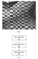
Fig. 4 is a schematic diagram illustrating effect of an input dot threshold matrix according to a preferable embodiment of the present application; -
Fig. 5 is a flowchart illustrating a multi-bit depth amplitude-modulation threshold screening method according to a preferable embodiment of the present application; and -
Fig. 6 is an effect diagram illustrating 3-bit amplitude-modulation screening output dots according to a preferable embodiment of the present application; and -
Fig. 7 is a schematic diagram illustrating an apparatus for generating multi-bit depth halftone amplitude-modulation dots according to an embodiment of the present application. - Hereinafter, the present application will be explained in detail with reference to the accompanying drawings in connection with the embodiments.
-
Fig. 1 is a flowchart illustrating a method for generating multi-bit depth halftone amplitude-modulation dots according to an embodiment of the present application. The method may include the following steps. - Step S10: scanning an input image to obtain a value of a current pixel Pxy, where x represents a lateral position index of the current pixel, and y represents a vertical position index of the current pixel.
- Step S20: obtaining gj from a preset multi-bit depth threshold matrix G by starting with i=0; if Pxy < gj, providing a screening output gray level gradation value of the printer Out=L-1-i.
- Step 320: increasing i and proceeding step S20 .
- L represents the number of a frequency-modulation screen gradation, L = 2 e , where e represents a bit depth value of the printer, i is an integer and i∈[0,L-1]. h is an index number of an element g arranged sequentially in G and h is provided to h = (y%n) × m + (x%m) + i × m × n. For example, for a 3*4 matrix, the index number of element a02 is 3, and the index number of element a23 is 12. gj is the element value of the ith line and jth row in G.
- As mentioned above, there is a need to transfer the dots data for many times in the related technology. However, according to the embodiments of the present application, the dots data does not need to be transferred for many times, such that the problem of bad timeliness can be solved. Meanwhile, the speed for generating the multi-bit depth halftone dots can be improved.
- In addition, the transferred dots data in related technology belong to quasi multi-bit depth dots data, and there are too many pixels with high gray level in the center of the amplitude-modulation screen. This will result in a serious impact to subsequent color correction and saturation, and thus the transferred dots data in related technology are not real multi-bit amplitude-modulation screen to achieve a stable output quality and color quality. However, in the embodiments of the present application, the threshold matrix screening controlling gradation which has the same number as the bit depth gradation of the apparatus can be used to achieve a stable output quality and color quality.
- Preferably, the multi-bit depth threshold matrix G is preset to:

- Preferably, the presetting step of the multi-bit depth threshold matrix G may include the following steps.
- Step 1): setting initial parameters as follows:
- a) M = (L-1) × n × m, where M represents the maximum of G;
- b) setting (L-1) cumulative arrays Si and initializing Si to Si =0; meanwhile, setting an index I of the cumulative arrays and the initial value of the index I is 0;
- c) setting a cumulative value of the threshold to C and the initial value of the threshold is 1.
- Step 2): transferring logic are given as follows:
- a) setting a = axy, where x = I%m, if x > Ui, x = Ui, y = I(L-1); and when I%(n × m) = 0, i = i + 1, % represents a modulo operation, axy represents a value of an element in xth line and yth row in a permutation matrix Ai, Ui represents the number of elements in ith line in the matrix Ai ;
- b) when axy ≤ (L-1) and Sa < (m × n), proceeding the following operations:
- traversing each value in a preset initial halftone one-bit amplitude-modulation screen threshold matrix T until tru = Sa ,
- where tru represents a value of an element in rth line and uth row in T;
- setting gj =C in the ith line of G, where j = u × m + r;
- increasing the threshold cumulative value C: C = C +1;
- increasing the cumulative array Sa : Sa = Sa + 1;
- correcting a = L-1, if it is not satisfied with the condition axy ≤ (L-1) and Sa < (m×n);
- c) setting I = I + 1;
- d) repeating the steps (a) to (c) until C > M , and then ending the operations.
- Preferably, the initial halftone one-bit amplitude-modulation screen threshold matrix T is preset to:

- The permutation matrix Ai is preset to:

where - 1) a i1 = a i2 = a i3 = ...... = aiU
i = i - 2) the number of elements in each line decreases from
line 0 to line L-1, and (U i-1 -Ui )-(Ui-U i+1)=1. - According to the preferable embodiments of the present application, the flowchart of the method for generating multi-bit depth halftone dots is shown in
Fig. 2 . -
Fig. 3 is a flowchart illustrating a method for transferring a single threshold matrix to a multi-bit depth threshold matrix according to a preferable embodiment of the present application. The method may include the following steps. - Step S102: providing the initial halftone one-bit amplitude-modulation screen threshold matrix T

- Parameters of the banner screen threshold matrix applied in the embodiment are given to m = n = 226, data effect of dot threshold matrix is shown in
Fig. 4 . - The initial halftone one-bit amplitude-modulation screen threshold matrix T is known to one skilled in the art. The threshold matrix T description cover all related or similar data when it is taken as an input parameter of the process of the present application.
- Step S104: calculating the gradation number L of the frequency-modulation screen based on bit depth value e of the apparatus via L = 2 e , in which the step S104 may further include:
- generating the permutation matrix Ai based on the value L, and permutation matrix Ai is preset to:

where i is an integer and i∈[0,L-1]; Ui represents the number of elements in ith line; axy represents any element in the permutation matrix Ai ; x represents the line index and y represents the serial number in each line from left to right. - Furthermore, the elements in the permutation matrix Ai meet the following conditions:
- 1) a i1 = a i2 = a i3 = ...... = aiU
i = i - 2) the number of elements in each line decreases from
line 0 to line L-1, and (U i-1-Ui )-(Ui-U i+1)=1. - In the embodiment, the bit depth of the apparatus is set to e = 3, i.e. 3-bit depth, L is set to 8, and thus the permutation matrix Ai can be calculated to:

- Then, the threshold matrix T is transferred to multi-bit depth threshold matrix G through the permutation matrix Ai , and the matrix G is set to

in which there are n×m elements in each line, and gj represent an element in ith line. - The specific transferring steps are given as follows.
- Step S106: setting initial parameters as follows:
- a) M = (L-1)×n×m, where M represents the maximum of G;
- b) setting (L-1) cumulative arrays Si and initialize Si to Si = 0 (i∈[0,L-1]); meanwhile, setting an index I of the cumulative arrays and the initial value of the index I is 0;
- c) setting a cumulative value of the threshold to C and the initial value of the threshold is 1.
- Step S108: obtaining a permutation matrix element a of the index I of the current cumulative array, a = axy, and searching for S based on the element a, where x = I%m, if x>Ui , x = Ui, y = I(L-1); and when I%(n×m) = 0, i = i + 1, % represents a modulo operation.
- Step S110: when axy ≤ (L-1) and Sa < (m×n) (condition 1), proceeding the following operations.
- Step S112: traversing each value in the matrix T until tru = Sa (condition 2), where r and u correspond to indexes in T in X and Y directions, respectively.
- Step S114: setting gj =C in the ith line of the threshold matrix G, and when j = u x m + r , increasing the threshold cumulative value C: C = C + 1, and increasing the cumulative array Sa : Sa = Sa + 1.
- Step S116: if the
condition 1 is not satisfied, then correcting a according to a = L - 1. - Step S118: increasing the index I of the current cumulative array I = I + 1.
- Step S120: repeating the steps S108 to S118 until C > M (condition 3), and then ending the operations.
- Next, image thresholds are compared by using the multi-bit depth threshold matrix G, and the corresponding screening data are output.
Fig. 5 shows the flowchart of screening process, and the screening process may include the following steps. - Step S202: scanning an input image to obtain a value of a current pixel Pxy, where x represents a lateral position index of the current pixel, and y represents a vertical position index of the current pixel.
- Step S204: calculating an index h corresponding to the current pixel Pxy in the multi-bit depth threshold matrix G according to h = (y%n) × m + (x%m) + i × m × n, where i represents the ith line in the threshold matrix G and i∈[0,L-1].
- Step S206: traversing the multi-bit depth threshold matrix G, and obtaining the threshold gj corresponding to the matrix G based on the index h.
- Step S208: comparing the screening threshold under the condition Pxy < gj (condition 4).
- Step S210: if Pxy < gj, then Out = L-1-i; otherwise, repeating the steps S204 to S206 until Pxy < gj, where Out represents the screening output gray level gradation, and Out∈[0,L-1].
- Step S212: determining whether all the pixels of the image are processed, if not, returning to the step S202, otherwise, ending the process.
- According to the embodiment, final halftone 3-bit dots are output through the above transferring and calculating steps.
Fig. 6 shows a screening effect diagram. -
Fig. 7 is a schematic diagram illustrating an apparatus for generating multi-bit depth halftone amplitude-modulation dots according to an embodiment of the present application, and the apparatus may include ascanning module 10, a generatingmodule 20 and a repeatingmodule 30. - The
scanning module 10 may be configured to scan an input image to obtain a value of a current pixel Pxy, where x represents a lateral position index of the current pixel, and y represents a vertical position index of the current pixel. - The generating
module 20 may be configured to obtain gj from a preset multi-bit depth threshold matrix G by starting with i=0. If Pxy < gj, then the generatingmodule 20 may further be configured to set a screening output gray level gradation value of the printer to Out=L-1-i. - The repeating
module 30 may be configured to increase i and to invoke thegenerating module 20. - L represents the number of a frequency-modulation screen gradation, L = 2 e , where e represents a bit depth value of the printer, gj is the element value of the ith line and jth row in G, and i is an integer and i∈[0,L-1].
- In view of the above, based on the existing halftone amplitude-modulation screening data obtained by searching in the threshold matrix, the characteristics of the multi-bit imaging apparatus can be used to their full potential according to requirements for dots. With the method and apparatus according to the present application, the output device with a multi-bit depth imaging depth can output a level full multi-bit halftone image with a high quality. Furthermore, the phenomenon of contour jaggies of the one-bit depth apparatus can be effectively resolved in order to output the amplitude-modulation dots with high resolution under low resolution.
- It will be readily apparent to those skilled in the art that the modules or steps of the present application may be implemented with a common computing device. In addition, the modules or steps of the present application can be concentrated or run in a single computing device or distributed in a network composed of multiple computing devices. Optionally, the modules or steps may be achieved by using codes of the executable program, so that they can be stored in the storage medium, or the plurality of the modules or steps can be fabricated into an individual integrated circuit module. Therefore, the present application is not limited to any particular hardware, software or combination thereof.
- The foregoing is only preferred embodiments of the present application, and it is not intended to limit the present application. Moreover, it will be apparent to those skilled in the art that various modifications and variations can be made to the present application. Thus, any modifications, equivalent substitutions, improvements etc. within the spirit and principle of the present application should be included within the scope of protection of the application.
Claims (8)
- A method for generating multi-bit depth halftone amplitude-modulation dots comprising:scanning an input image to obtain a value of a current pixel Pxy, where x represents a lateral position index of the current pixel, and y represents a vertical position index of the current pixel;obtaining gj from a preset multi-bit depth threshold matrix G by starting with i=0, anddetermining if Pxy < gj,if yes, providing a screening output gray level gradation value of a printer Out=L-1-i; otherwise,increasing i and repeating the determining and providing steps;where L represents the number of a frequency-modulation screen gradation, L = 2 e , e represents a bit depth value of the printer, i is an integer and i∈[0,L-1], h is an index number of an element g arranged sequentially in G and h is provided as h = (y%n) × m + (x%m) + i × m × n, andgj is an element value of ith line and jth row in G.
- The method according to claim 1, wherein the multi-bit depth threshold matrix G is preset as

where m represents a width of the matrix, and n represents a height of the matrix. - The method according to claim 2, wherein the multi-bit depth threshold matrix G is preset by:1) setting initial parameters, comprising:a) M = (L - 1) × n × m, where M represents a maximum of G;b) setting (L-1) cumulative arrays Si and initializing Si to Si = 0; meanwhile, setting an index I of the cumulative arrays and an initial value of the index I is 0;c) setting a cumulative threshold as C and the initial value of C is 1;2) transferring logic are given as follows:a) setting a = axy,
where x=I%m, if x>Ui, x=Ui, y = I(L - 1);
when I%(n × m) = 0, i = i + 1, wherein % represents a modulo operation,
axy represents a value of an element in xth line and yth row in a permutation matrix Ai , Ui represents a number of elements in ith line in the matrix Ai ;b) when axy ≤ (L-1) and Sa < (m × n), proceeding the following operations:traversing each value in a preset initial halftone one-bit amplitude-modulation screen threshold matrix T until tru = Sa, where tru represents a value of an element in rth line and uth row in T;setting gj =C in ith line of G, where j = u × m + r;increasing the threshold cumulative value C: C = C + 1;increasing the cumulative array Sa : Sa = Sa +1;correcting a = L-1 if it is not satisfied with a condition of axy ≤ (L-1) and Sa < (m×n);c) setting I = I + 1;d) repeating the steps (a) to (c) until C > M, and then ending the operations. - The method according to claim 3, wherein the initial halftone one-bit amplitude-modulation screen threshold matrix T is preset as

where txy ∈[1,m×n] and txy in the matrix T meets element anisotropy for each two; and
the permutation matrix Ai is preset to
wherein1) a i1 = a i2 = a i3 = ...... = aiUi = i2) the number of elements in each line decreases from line 0 to line L-1, and (U i-1 - Ui) - (Ui - U i+1) = 1. - An apparatus for generating multi-bit depth halftone amplitude-modulation dots, comprising:a scanning module configured to scan an input image to obtain a value of a current pixel Pxy, wherein x represents a lateral position index of the current pixel, and y represents a vertical position index of the current pixel;a generating module configured to obtain gi from a preset multi-bit depth threshold matrix G by starting with i=0, if Pxy < gj, then the generating module is further configured to set a screening output gray level gradation value of a printer as Out=L-1-i; anda repeating module configured to increase i and to invoke the generating module;wherein L represents number of a frequency-modulation screen gradation, L = 2 e , e represents a bit depth value of the printer, i is an integer and i∈[0,L-1], h is an index number of an element g arranged sequentially in G and h is provided to h = (y%n) × m + (x%m) + i × m × n, and gj is an element value of the ith line and jth row in G.
- The apparatus according to claim 5, wherein the multi-bit depth threshold matrix G is preset as

where m represents a width of the matrix, and n represents a height of the matrix. - The apparatus according to claim 6, wherein the presetting step of the multi-bit depth threshold matrix G comprises:1) setting initial parameters comprising:a) M = (L - 1) × n × m, where M represents the maximum of G;b) setting (L-1) cumulative arrays Si and initializing Si to Si = 0; meanwhile, setting an index I of the cumulative arrays and an initial value of the index I is 0;c) setting a cumulative threshold as C and the initial value of the threshold C is 1;2) transferring logic are given as follows:a) setting a = axy, where x = I%m, if x > Ui, x = Ui, y = I(L - 1); and when I%(n × m) = 0, i=i+1, % represents a modulo operation, axy represents a value of an element in xth line and yth row in a permutation matrix Ai , Ui represents the number of elements in ith line in the matrix Ai ;b) when axy ≤ (L-1) and Sa < (m × n), proceeding the following operations:traversing each value in a preset initial halftone one-bit amplitude-modulation screen threshold matrix T until tru = Sa,where tru represents a value of an element in rth line and uth row in T;setting gj =C in the ith line of G, where j = u × m + r;increasing the threshold cumulative value C: C = C + 1;increasing the cumulative array Sa : Sa = Sa +1;correcting a = L - 1 if it is not satisfied a condition of axy ≤ (L - 1) and Sa < (m × n),;c) setting I = I + 1;d) repeating the steps (a) to (c) until C > M, and then ending the operations.
- The apparatus according to claim 7, wherein the initial halftone one-bit amplitude-modulation screen threshold matrix T is preset as

where txy∈[1,m×n] and txy in the matrix meets element anisotropy for each two; and
the permutation matrix Ai is preset to
wherein1) a i1 = a i2 = a i3 = ...... = aiUi = i2) the number of elements in each line decreases from line 0 to line L-1, and (U i-1 - Ui ) - (Ui - U i+1) = 1.
Applications Claiming Priority (2)
| Application Number | Priority Date | Filing Date | Title |
|---|---|---|---|
| CN201110390759.1A CN103139440B (en) | 2011-11-30 | 2011-11-30 | Method and device for multi-bit-depth halftone amplitude modulation dot generating |
| PCT/CN2012/075724 WO2013078836A1 (en) | 2011-11-30 | 2012-05-18 | Method and apparatus for generating multi-bit deep halftone amplitude modulation dot |
Publications (2)
| Publication Number | Publication Date |
|---|---|
| EP2787719A1 true EP2787719A1 (en) | 2014-10-08 |
| EP2787719A4 EP2787719A4 (en) | 2015-01-07 |
Family
ID=48498706
Family Applications (1)
| Application Number | Title | Priority Date | Filing Date |
|---|---|---|---|
| EP12853124.1A Ceased EP2787719A4 (en) | 2011-11-30 | 2012-05-18 | METHOD AND APPARATUS FOR GENERATING MULTI-BIT DEHIN DAMPING AMPLITUDE POINT IN DEPTH |
Country Status (5)
| Country | Link |
|---|---|
| US (1) | US8861034B2 (en) |
| EP (1) | EP2787719A4 (en) |
| JP (1) | JP5740539B2 (en) |
| CN (1) | CN103139440B (en) |
| WO (1) | WO2013078836A1 (en) |
Families Citing this family (7)
| Publication number | Priority date | Publication date | Assignee | Title |
|---|---|---|---|---|
| CN103978783B (en) * | 2014-05-31 | 2015-11-11 | 齐鲁工业大学 | A kind of control method for electrostatic digital printed site contrast |
| JP6580091B2 (en) * | 2017-07-05 | 2019-09-25 | キヤノン株式会社 | Image processing apparatus, image processing method, and program |
| CN111988488B (en) * | 2020-09-03 | 2021-12-17 | 北大方正集团有限公司 | Network point generation method, device, electronic device and storage medium |
| CN115482365B (en) * | 2021-06-16 | 2025-09-16 | 深圳市汉森软件股份有限公司 | Halftone processing method, device, equipment and storage medium for three-dimensional model |
| US12373661B2 (en) | 2023-12-14 | 2025-07-29 | Ricoh Company, Ltd. | Vectorized interleave of bit planes |
| CN119444883B (en) * | 2024-09-26 | 2025-05-30 | 北京大学 | Halftone image generation method, device and equipment |
| CN120543666B (en) * | 2025-04-18 | 2026-02-03 | 北京大学 | Halftone dot generation method, device and equipment based on amplitude modulation screening |
Family Cites Families (15)
| Publication number | Priority date | Publication date | Assignee | Title |
|---|---|---|---|---|
| DE3130207C2 (en) * | 1980-07-31 | 1986-03-06 | Matsushita Research Institute Tokyo, Inc., Kawasaki, Kanagawa | Dot printer with a recording head |
| WO1995002938A1 (en) * | 1993-07-12 | 1995-01-26 | Agfa-Gevaert Naamloze Vennootschap | High quality multilevel halftoning for colour images with reduced memory requirements |
| JP2001088356A (en) * | 1999-09-27 | 2001-04-03 | Ricoh Co Ltd | Printer control device |
| JP2004025621A (en) * | 2002-06-25 | 2004-01-29 | Canon Inc | Halftone dot expression method, computer program, and computer-readable storage medium |
| CN1172263C (en) * | 2002-12-30 | 2004-10-20 | 北京北大方正电子有限公司 | Frequency modulation Internet access method for copying images on multiple position imaging depth equipment |
| JP4282467B2 (en) * | 2003-12-24 | 2009-06-24 | Necエンジニアリング株式会社 | Image area separation method |
| JP4260714B2 (en) * | 2004-09-16 | 2009-04-30 | 大日本印刷株式会社 | Printing method of image consisting of halftone dots and image conversion method and apparatus |
| US7616347B2 (en) * | 2005-04-29 | 2009-11-10 | International Business Machines Corporation | System and method for multi-bit halftoning |
| CN100377567C (en) * | 2005-10-26 | 2008-03-26 | 北京北大方正电子有限公司 | Control method of frequency modulation and amplitude modulation mixed dot pattern on multi-bit imaging depth equipment |
| CN100377566C (en) * | 2005-10-26 | 2008-03-26 | 北京北大方正电子有限公司 | FM-AM Mixed Halftone Image Processing Method on Multi-bit Imaging Depth Device |
| US7830569B2 (en) * | 2006-03-31 | 2010-11-09 | Eastman Kodak Company | Multilevel halftone screen and sets thereof |
| CN100393099C (en) * | 2006-08-31 | 2008-06-04 | 北京北大方正电子有限公司 | Control Method of Frequency Modulation and AM Hybrid Dot Hierarchy Continuous Modulation |
| JP5132496B2 (en) * | 2008-02-06 | 2013-01-30 | キヤノン株式会社 | Image processing apparatus, image processing method, program thereof, and storage medium |
| JP5342357B2 (en) * | 2009-07-27 | 2013-11-13 | 大日本スクリーン製造株式会社 | Image data creation apparatus and image data creation method |
| JP5482189B2 (en) * | 2009-12-24 | 2014-04-23 | セイコーエプソン株式会社 | Print control apparatus, print control method, and computer program |
-
2011
- 2011-11-30 CN CN201110390759.1A patent/CN103139440B/en not_active Expired - Fee Related
-
2012
- 2012-05-18 WO PCT/CN2012/075724 patent/WO2013078836A1/en not_active Ceased
- 2012-05-18 US US14/128,351 patent/US8861034B2/en active Active
- 2012-05-18 JP JP2014543752A patent/JP5740539B2/en not_active Expired - Fee Related
- 2012-05-18 EP EP12853124.1A patent/EP2787719A4/en not_active Ceased
Also Published As
| Publication number | Publication date |
|---|---|
| CN103139440A (en) | 2013-06-05 |
| US20140132992A1 (en) | 2014-05-15 |
| WO2013078836A1 (en) | 2013-06-06 |
| JP5740539B2 (en) | 2015-06-24 |
| EP2787719A4 (en) | 2015-01-07 |
| US8861034B2 (en) | 2014-10-14 |
| CN103139440B (en) | 2015-06-17 |
| JP2014533919A (en) | 2014-12-15 |
Similar Documents
| Publication | Publication Date | Title |
|---|---|---|
| US8861034B2 (en) | Method and apparatus for generating multi-bit depth halftone amplitude-modulation dots | |
| US8649061B2 (en) | Laser print apparatus with dual halftones | |
| JP2003046777A (en) | Mask creation method, image processing apparatus, software program, and mask data | |
| CN101404714B (en) | An image processing method and device | |
| JP2014533919A5 (en) | ||
| EP2518991B1 (en) | Halftone screen producing apparatus and method of producing halftone screen | |
| US20190116291A1 (en) | Selecting color states | |
| CN100393099C (en) | Control Method of Frequency Modulation and AM Hybrid Dot Hierarchy Continuous Modulation | |
| EP2180687A1 (en) | Image processing apparatus and image processing method | |
| Chandu et al. | Direct multi-bit search (DMS) screen algorithm | |
| JP3762800B2 (en) | How to create a mesh screen | |
| JP4596473B2 (en) | Dither matrix creation method, apparatus, image forming apparatus, program, and recording medium | |
| CN102263881B (en) | Method and device for processing halftone image frequency modulation mesh hanging | |
| EP3054663B1 (en) | Image processing device, printing apparatus, image processing method, and program | |
| JP3688938B2 (en) | Image data generation method, apparatus and recording medium | |
| JP4479663B2 (en) | Image processing apparatus, image processing method, and image processing program for halftone processing using fixed cells | |
| JP3917634B2 (en) | How to create a mesh screen | |
| JPS60226279A (en) | Half tone recording device | |
| US20020060812A1 (en) | Image processing method and image processing apparatus | |
| JP5838087B2 (en) | Image processing apparatus, image processing method, and image processing program | |
| JP4222187B2 (en) | Image processing apparatus, image processing method, and image processing program | |
| US20060139666A1 (en) | Method for converting printing data and device using the same | |
| JP2012134890A (en) | Image processing system | |
| JP2011160490A (en) | Image forming apparatus, image forming method, and image forming program | |
| JP2001036745A (en) | Apparatus and method for creating matrix for image processing |
Legal Events
| Date | Code | Title | Description |
|---|---|---|---|
| PUAI | Public reference made under article 153(3) epc to a published international application that has entered the european phase |
Free format text: ORIGINAL CODE: 0009012 |
|
| 17P | Request for examination filed |
Effective date: 20131218 |
|
| AK | Designated contracting states |
Kind code of ref document: A1 Designated state(s): AL AT BE BG CH CY CZ DE DK EE ES FI FR GB GR HR HU IE IS IT LI LT LU LV MC MK MT NL NO PL PT RO RS SE SI SK SM TR |
|
| A4 | Supplementary search report drawn up and despatched |
Effective date: 20141208 |
|
| RIC1 | Information provided on ipc code assigned before grant |
Ipc: G06K 15/02 20060101ALI20141202BHEP Ipc: H04N 1/405 20060101ALI20141202BHEP Ipc: H04N 1/40 20060101AFI20141202BHEP |
|
| DAX | Request for extension of the european patent (deleted) | ||
| 17Q | First examination report despatched |
Effective date: 20151214 |
|
| REG | Reference to a national code |
Ref country code: DE Ref legal event code: R003 |
|
| STAA | Information on the status of an ep patent application or granted ep patent |
Free format text: STATUS: THE APPLICATION HAS BEEN REFUSED |
|
| 18R | Application refused |
Effective date: 20170207 |