EP2787581A1 - Implantable cable connection device - Google Patents
Implantable cable connection device Download PDFInfo
- Publication number
- EP2787581A1 EP2787581A1 EP13162255.7A EP13162255A EP2787581A1 EP 2787581 A1 EP2787581 A1 EP 2787581A1 EP 13162255 A EP13162255 A EP 13162255A EP 2787581 A1 EP2787581 A1 EP 2787581A1
- Authority
- EP
- European Patent Office
- Prior art keywords
- cable
- cable connector
- connector
- connection device
- elements
- Prior art date
- Legal status (The legal status is an assumption and is not a legal conclusion. Google has not performed a legal analysis and makes no representation as to the accuracy of the status listed.)
- Withdrawn
Links
Images


Classifications
-
- H—ELECTRICITY
- H01—ELECTRIC ELEMENTS
- H01R—ELECTRICALLY-CONDUCTIVE CONNECTIONS; STRUCTURAL ASSOCIATIONS OF A PLURALITY OF MUTUALLY-INSULATED ELECTRICAL CONNECTING ELEMENTS; COUPLING DEVICES; CURRENT COLLECTORS
- H01R31/00—Coupling parts supported only by co-operation with counterpart
- H01R31/02—Intermediate parts for distributing energy to two or more circuits in parallel, e.g. splitter
-
- A—HUMAN NECESSITIES
- A61—MEDICAL OR VETERINARY SCIENCE; HYGIENE
- A61M—DEVICES FOR INTRODUCING MEDIA INTO, OR ONTO, THE BODY; DEVICES FOR TRANSDUCING BODY MEDIA OR FOR TAKING MEDIA FROM THE BODY; DEVICES FOR PRODUCING OR ENDING SLEEP OR STUPOR
- A61M60/00—Blood pumps; Devices for mechanical circulatory actuation; Balloon pumps for circulatory assistance
- A61M60/10—Location thereof with respect to the patient's body
- A61M60/122—Implantable pumps or pumping devices, i.e. the blood being pumped inside the patient's body
- A61M60/165—Implantable pumps or pumping devices, i.e. the blood being pumped inside the patient's body implantable in, on, or around the heart
- A61M60/178—Implantable pumps or pumping devices, i.e. the blood being pumped inside the patient's body implantable in, on, or around the heart drawing blood from a ventricle and returning the blood to the arterial system via a cannula external to the ventricle, e.g. left or right ventricular assist devices
- A61M60/183—Implantable pumps or pumping devices, i.e. the blood being pumped inside the patient's body implantable in, on, or around the heart drawing blood from a ventricle and returning the blood to the arterial system via a cannula external to the ventricle, e.g. left or right ventricular assist devices drawing blood from both ventricles, e.g. bi-ventricular assist devices [BiVAD]
-
- A—HUMAN NECESSITIES
- A61—MEDICAL OR VETERINARY SCIENCE; HYGIENE
- A61M—DEVICES FOR INTRODUCING MEDIA INTO, OR ONTO, THE BODY; DEVICES FOR TRANSDUCING BODY MEDIA OR FOR TAKING MEDIA FROM THE BODY; DEVICES FOR PRODUCING OR ENDING SLEEP OR STUPOR
- A61M60/00—Blood pumps; Devices for mechanical circulatory actuation; Balloon pumps for circulatory assistance
- A61M60/80—Constructional details other than related to driving
- A61M60/855—Constructional details other than related to driving of implantable pumps or pumping devices
- A61M60/871—Energy supply devices; Converters therefor
- A61M60/878—Electrical connections within the patient's body
-
- A—HUMAN NECESSITIES
- A61—MEDICAL OR VETERINARY SCIENCE; HYGIENE
- A61M—DEVICES FOR INTRODUCING MEDIA INTO, OR ONTO, THE BODY; DEVICES FOR TRANSDUCING BODY MEDIA OR FOR TAKING MEDIA FROM THE BODY; DEVICES FOR PRODUCING OR ENDING SLEEP OR STUPOR
- A61M60/00—Blood pumps; Devices for mechanical circulatory actuation; Balloon pumps for circulatory assistance
- A61M60/80—Constructional details other than related to driving
- A61M60/855—Constructional details other than related to driving of implantable pumps or pumping devices
- A61M60/871—Energy supply devices; Converters therefor
- A61M60/88—Percutaneous cables
-
- A—HUMAN NECESSITIES
- A61—MEDICAL OR VETERINARY SCIENCE; HYGIENE
- A61M—DEVICES FOR INTRODUCING MEDIA INTO, OR ONTO, THE BODY; DEVICES FOR TRANSDUCING BODY MEDIA OR FOR TAKING MEDIA FROM THE BODY; DEVICES FOR PRODUCING OR ENDING SLEEP OR STUPOR
- A61M2205/00—General characteristics of the apparatus
- A61M2205/04—General characteristics of the apparatus implanted
-
- A—HUMAN NECESSITIES
- A61—MEDICAL OR VETERINARY SCIENCE; HYGIENE
- A61M—DEVICES FOR INTRODUCING MEDIA INTO, OR ONTO, THE BODY; DEVICES FOR TRANSDUCING BODY MEDIA OR FOR TAKING MEDIA FROM THE BODY; DEVICES FOR PRODUCING OR ENDING SLEEP OR STUPOR
- A61M2205/00—General characteristics of the apparatus
- A61M2205/35—Communication
- A61M2205/3507—Communication with implanted devices, e.g. external control
- A61M2205/3523—Communication with implanted devices, e.g. external control using telemetric means
-
- A—HUMAN NECESSITIES
- A61—MEDICAL OR VETERINARY SCIENCE; HYGIENE
- A61M—DEVICES FOR INTRODUCING MEDIA INTO, OR ONTO, THE BODY; DEVICES FOR TRANSDUCING BODY MEDIA OR FOR TAKING MEDIA FROM THE BODY; DEVICES FOR PRODUCING OR ENDING SLEEP OR STUPOR
- A61M2205/00—General characteristics of the apparatus
- A61M2205/82—Internal energy supply devices
- A61M2205/8262—Internal energy supply devices connectable to external power source, e.g. connecting to automobile battery through the cigarette lighter
-
- A—HUMAN NECESSITIES
- A61—MEDICAL OR VETERINARY SCIENCE; HYGIENE
- A61M—DEVICES FOR INTRODUCING MEDIA INTO, OR ONTO, THE BODY; DEVICES FOR TRANSDUCING BODY MEDIA OR FOR TAKING MEDIA FROM THE BODY; DEVICES FOR PRODUCING OR ENDING SLEEP OR STUPOR
- A61M60/00—Blood pumps; Devices for mechanical circulatory actuation; Balloon pumps for circulatory assistance
- A61M60/10—Location thereof with respect to the patient's body
- A61M60/122—Implantable pumps or pumping devices, i.e. the blood being pumped inside the patient's body
- A61M60/126—Implantable pumps or pumping devices, i.e. the blood being pumped inside the patient's body implantable via, into, inside, in line, branching on, or around a blood vessel
- A61M60/148—Implantable pumps or pumping devices, i.e. the blood being pumped inside the patient's body implantable via, into, inside, in line, branching on, or around a blood vessel in line with a blood vessel using resection or like techniques, e.g. permanent endovascular heart assist devices
-
- A—HUMAN NECESSITIES
- A61—MEDICAL OR VETERINARY SCIENCE; HYGIENE
- A61M—DEVICES FOR INTRODUCING MEDIA INTO, OR ONTO, THE BODY; DEVICES FOR TRANSDUCING BODY MEDIA OR FOR TAKING MEDIA FROM THE BODY; DEVICES FOR PRODUCING OR ENDING SLEEP OR STUPOR
- A61M60/00—Blood pumps; Devices for mechanical circulatory actuation; Balloon pumps for circulatory assistance
- A61M60/20—Type thereof
- A61M60/205—Non-positive displacement blood pumps
- A61M60/216—Non-positive displacement blood pumps including a rotating member acting on the blood, e.g. impeller
-
- H—ELECTRICITY
- H01—ELECTRIC ELEMENTS
- H01R—ELECTRICALLY-CONDUCTIVE CONNECTIONS; STRUCTURAL ASSOCIATIONS OF A PLURALITY OF MUTUALLY-INSULATED ELECTRICAL CONNECTING ELEMENTS; COUPLING DEVICES; CURRENT COLLECTORS
- H01R2201/00—Connectors or connections adapted for particular applications
- H01R2201/12—Connectors or connections adapted for particular applications for medicine and surgery
Definitions
- the invention is in the field of mechanics and electrical engineering and is particularly applicable in medical technology.
- the invention particularly relates to a cable connection device which is implantable.
- Such percutaneous cables d.
- cables located in a region of their course within the patient's body and in another area of their course outside the patient's body present a risk of infection and inflammation. It is therefore desirable to have a corresponding cable in the event of complications can be easily removed and / or replaced.
- a cable connector is known, which is designed as a so-called Y-cable, ie with a connector and a permanently attached to this cable with multiple lines, which branch to two separate cables, each of the separate cables in turn a connector having.
- a cable connector is provided for the electrical connection of a percutaneous cable with two implantable pumps. The pumps are used to pump blood in the bloodstream.
- the present invention is based on the background of the prior art, the object to provide an implantable cable connector, which is particularly simple and stable and is particularly easy to handle in the implantation and the production of the connectors.
- the invention relates to an implantable cable connection device with a cable connector having two or more connector elements, with each of which an implantable cable is connectable by a plug connection, wherein the cable connector is formed as a rigid body made of a biocompatible material.
- a particularly advantageous embodiment of the invention provides that at least two, in particular three or more connector elements are arranged on the same side of the cable connector.
- a further advantageous embodiment of the invention provides that all plug connection elements are arranged on the same side of the cable connector.
- the cable connector this can be implanted so that the connector elements are each on the side of the cable connector, which can be easily reached from the outside by a minimal intervention by a minimum opening of the patient's body. The cable connector itself must then not be removed from the patient's body to replace the connectors.
- the plug connection elements can advantageously be arranged on the smallest or narrowest of the side surfaces of the cable connector.
- the invention can also be advantageously configured in that the plug-in axes of the connector elements, which are arranged together on one side of the cable connector, are aligned parallel to each other. Also, by a parallel, in particular rigid arrangement of the plug-in axes of the connector elements on the cable connector, the handling of the connectors can be simplified. Under the plug-in axes of the connector elements is in each case understood the direction in which a cable is plugged with the respective complementary connector element on the cable connector arranged on the connector element. In common hermaphrodisiac connectors, the plug-in axis is parallel to the longitudinal axis of the connector pins or the corresponding sockets.
- a parallel orientation of the stub axles of the connector elements also means that they can be performed with minimal distance from each other and that the corresponding complementary connector elements of cables can be arranged in the same way with minimum distance from each other outside of the cable connector. The overall space required and required space of the cable connection device is thus minimized.
- the invention is also realized in that the cable connector has a flat surface formed side on which the connector elements are arranged, and that all other boundary surfaces of the cable connector are convex rounded.
- a cable connector which is largely rounded off on its outer sides, can be readily implanted in a patient's body, in particular without the risk of special tissue loads in the rounded regions of the cable connector. Even with a movement of the tissue in which the cable connector is embedded, no injuries are to be feared.
- the cable connector is formed substantially hemispherical rounded.
- the cable connector may also take the form of a halved ellipsoidal or other rounded body.
- the basic form may be that of a cuboid.
- a further advantageous embodiment of the invention provides that the cable connector is designed as a housing with at least one interior.
- a cable connector produced as a compact body can on the one hand connect the various plug connection elements to one another by means of the favorable internal guidance of lines in a small space and furthermore also have an interior in which, for example, an electrical energy storage / accumulator or an electrically active element, for example an electrical circuit,
- a device for wireless communication can be arranged.
- a transponder can be arranged, which allows identification without a power supply is necessary (radio-tag).
- the interior can be filled with an adhesive, a potting compound or a fluid, but it can also remain a cavity free.
- a control device for one or more blood pump motors may be arranged.
- a microcontroller or another programmable device can be provided there.
- the cable connector consists exclusively of metal and / or glass and / or ceramic on its outer sides.
- These materials are highly biocompatible, i. H. tissue-compatible, and long-term stability, so that an existing of such a material cable connector is long-term implantable.
- the outer surfaces are advantageously designed smooth.
- the housing of the cable connector can also consist of several parts, which are joined gas-tight to the outside of the cable connector, in particular welded together, glued or potted.
- a metal element of the cable connector with a glass part be merged.
- the glass part can in turn be sealed gas-tight with a ceramic.
- a metal can also be gas-tightly connected to a ceramic or a glass by means of a metal brazing. All these joining techniques have in common that they combine a reliable fixation with simultaneous gas-tight sealing and chemical and physical strength.
- a cable connector when used in conjunction with one or more cardiac assistive blood pumps, may be placed in the space between the then-usually somewhat-reduced heart muscle and pericardium. It is also a subcutaneous arrangement of the cable connector possible, and it can be provided on this example, eyelets for sewing on the body tissue.
- the invention also relates to a cable connection device with a cable connector, a first percutaneous cable inserted therein and at least one second cable inserted into the cable connector and an implant connected to the second cable, in particular a blood pump.
- a third cable connected to the cable connector by a plug connection and a further implant connected to this third cable, in particular also an implanted blood pump, may be provided.
- the cable connection device may potentially include not only the cable connector with connector devices, but also the corresponding cables inserted therein and blood pumps or alternative implants connected thereto. Also, an inserted percutaneous cable connected to the cable connector may be part of the cable connection device.
- the cable connecting device may thus comprise a total of a system of a plurality of implants, in particular pumps, which are connected by means of cable connections via a cable connector with a percutaneous cable, which is easily accessible outside the patient's body to a cable connection.
- the cable connector in particular its housing, can also have at least one, in particular two coupling elements, for example screw threads, bayonet receptacles or the like for a fixing element, by means of which the connector is easy to manipulate, especially in a cable plugging operation.
- at least one, in particular two coupling elements for example screw threads, bayonet receptacles or the like for a fixing element, by means of which the connector is easy to manipulate, especially in a cable plugging operation.
- An advantageous embodiment of the invention also provides that on the outside of the cable connector at least two connector elements are provided side by side and that in addition a locking device is provided which, as long as one of the connectors is released, the release of the other connector blocked, in which case in particular a Locking element is provided which has two cover elements for at least partial cover each of a plug connection, wherein the locking element between two end positions is movable and in each of the end positions in each case a plug connection is blocked.
- Such a locking device prevents inadvertent release of two connectors on the cable connector at the same time, which can lead to reversed cables when reinserting. This is particularly undesirable and risky when two cable connections are made to two blood pumps located in different parts of a patient's heart or at various locations with respect to the heart in the periphery or generally in the bloodstream, the exchange of which can be detrimental.
- An advantageous method for implanting a cable connection device of the type according to the invention can also provide that the cable connector is arranged in the patient's body and then at least one, in particular two or three implantable cables are connected to the cable connector by means of plug connections.
- implantable elements such as blood pumps, which are to be connected to the cable connector can advantageously already before the implantation of the cable connector or after the implantation of the cable connector In any case, they do not have to be inserted simultaneously with the cable connector.
- the invention also relates to a method for exchanging a plurality of implantable cables connected to a cable connector according to the invention, in which first the plug connection of a first cable is released and a new first cable is connected to the cable connector by means of the plug connection and the plug connection of a second cable is released thereon a connector of the cable connector is made to a new second cable, wherein in particular the first and the second cable are each connected to a blood pump.
- connection also relates to a method for exchanging an implanted cable connected to a cable connector according to the invention, in which first a holding tool is connected to a coupling element of the cable connector, then the plug connection of the cable is released and a new cable is connected to the cable connector by means of a plug connection ,
- the cable connector can be easily held as a rigid body from the outside, while connectors are dissolved or plugged.
- the cable connector can remain implanted, and it comes only minimally in contact with alien instruments.
- a coupling element may in principle have a mechanical fit, such as a screw thread or a bayonet closure, or it may also be formed magnetically, for example, by a magnet attached to the cable connector and / or a holding tool.
- An advantageous use of the cable connection device provides that the cable connection device is connected to two heart support pumps and arranged together with these directly on a heart, in particular fixed on this or on the pericardium.
- An advantageous method for implanting a cable connecting device provides that the cable connector with two heart support pumps is electrically connected and temporally before or after the pericardium of a patient's heart is fixed.
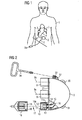
- FIG. 1 schematically shows a front view of a patient's body 1, in which a cable connector 2 of a cable connection device is implanted.
- the cable connector 2 is connected by means of a first implantable cable 3, which is designed as a percutaneous cable, with a first plug connection 3a outside the patient's body.
- percutaneous cable usually refers to a cable that penetrates the skin or other part of the boundary surface between the patient's body and the outside world.
- a percutaneous cable may also refer to an implantable cable that extends completely within the patient's body and terminates at a terminal device with which a cable extending outside of the patient's body can, for example, be inductively coupled through the skin. It can also be provided that only one plug connection 3a of the percutaneous cable is let into the skin and penetrates it.
- a second implantable cable 4 which connects the cable connector 2 to a first blood pump 5, is connected to the cable connector 2.
- a third implanted cable 6 is connected to the cable connector 2 on the one hand and a second blood pump 7 on the other hand.
- the implanted cables 3, 4, 6 are electrically connected to the cable connector 2 in each case via plug connections.
- the implanted cables are connected at their ends remote from the cable connector 2 by means of a respective further connector 3a, in each case with a further element, for example with the blood pumps 5, 7.
- the implanted cables 4, 6 can also be permanently and permanently connected to the respective blood pumps 5, 7.
- the two blood pumps 5, 7, via a single, percutaneous cable 3 can be controlled from outside the patient's body, required for the implementation of a cable portion of the skin, which is opened and permanently is traversed by a foreign body, minimized.
- a particularly advantageous embodiment results from the fact that the percutaneous cable 3 is circular in cross-section, in order to minimize the contact area between the cable and the skin of the patient's body as a whole and especially at the point of penetration through the skin.
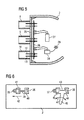
- FIG. 2 shows schematically and partially in section a cable connector 2 in more detail, wherein the cable connector 2 has three connector elements 8, 9, 10.
- the individual connector elements On the cable connector 2 each have a hollow metal cylinder 11 which is fixed as a plug sleeve on the cable connector 2 and which has a cylinder bottom 11 a, which is fluid-tightly connected to the cable connector 2.
- the cylinder bottom 11a has recesses, through which the plug pins 12, 13 are electrically insulated and fluid-tight in that they are sealed in the cylinder bottom 11a by means of a glass filling 14 in a fluid-tight manner.
- the plug pins 12, 13 are each connected via solder joints 15 with a line, such as a copper wire 16, in turn, the contact of the connector pins 12, 13 with other connector pins of the remaining connector elements 8, 9 or electronic elements in the interior of the cable connector 2 or an energy storage in the interior of the cable connector 2 produces.
- the plug 17 has plug sleeves 18 which can be plugged onto the plug pins 12, 13 in order to produce galvanic contact therewith.
- the plug sleeves 18 are in turn connected to conductors which are guided within the plug 17 to the connected implanted cable.
- a connector housing 19 is provided which has a shape corresponding to the cylinder 11 and which is attachable to the cylinder 11.
- an O-ring 20 is provided in the plug housing 19 in an inner circumferential groove made of an elastomer which seals fluid-tight on the metal cylinder 11 outside.
- a fuse may be provided which holds the plug 17 to the cable connector 2, for example by a union nut which is screwed to the cable connector 2, or by a bayonet connection between the plug 17 and the metal cylinder eleventh
- FIG. 2 shows that the cable connector 2 has a flat front surface 21 to which the connector elements 8, 9, 10 are fixed such that their through axles 8a, 9a, 10a are parallel to each other.
- the housing part of the cable connector 2, which adjoins the flat front plate, which forms the flat front surface 21, is formed, for example, as a spherical cap or as part of a rotational ellipsoid and consists for example, made of metal, in particular titanium, or a ceramic.
- the connections between the metal and the ceramic can be made fluid-tight by melting the metal or by interim storage of a glass solder or metal solder. It is also conceivable a fluid-tight pressing of the elements by pressure application.
- Fig. 2 are also exemplary coupling elements, namely holding eyes 30, 31, shown, and a housing projection 32 in which a threaded bore 33 is located, into which a holding tool 34 can be screwed for manipulation.
- FIG. 3 shows a cable connector 2 'with only two connector elements 8, 9 on a flat front surface, wherein the connector elements 8, 9 are aligned with their respective through axles 8a, 9a parallel to each other.
- an external thread 21 is shown on the metal cylinder in the base area near the front surface of the cable connector 2 ', which cooperates for fastening the connector with an internal thread 22 of a plug housing 19'.
- FIG. 4 shows in comparison a cable connector 2 "with a rounded housing part 23 and a front plate 24, which is also rounded, but it has a weaker rounding than the housing part 23.
- On the front panel 24 of the cable connector 2" are three connector elements 8 ', 9', 10 'attached. These are due to the curvature of the front plate 24 with its through axles 8'a, 9'a, 10'a not parallel to each other, but at an angle between 10 ° and 30 ° to each other. Nevertheless, all plug-in elements from one side of the cable connector 2 "are plugged in and also released again.
- FIG. 5 a cable connector with connector elements 8, 9, 10 is shown, where there are plug pins 12, 13, the front panel 25 of the cable connector gas-tight, for example, sealed through molten glass, enforce.
- the plug pins 12, 13 are continued in the interior of the housing of the cable connector 2 and enforce there a circuit board 26.
- the connector pins 12, 13 are soldered to the circuit board 26 and various conductors located on this.
- On the circuit board 26 can also electrical or electronic elements and a conductor track guide may be provided which desirably connects different connector pins of the cable connector 2 with each other or with an electronic component which is located in the interior of the cable connector 2.
- An electronic device 28 may also be connected to the printed circuit board 26 via plug pins, serving for wireless communication between implants connected to the cable connector and a device outside the patient's body.
- the electronic device 28 with an antenna 29 is inside the cable connector or a cavity in the cable connector 2 is provided.
- the cable connecting device according to the invention with a cable connector and corresponding implanted cables and optionally connected to these implanted blood pumps or other elements is used for safe operation of the implants, which can easily be replaced in case of errors in the connection technology cables without implanted, to the cable connected elements must necessarily be removed or replaced.
- FIG. 6 shows a front view of a cable connector 2 with connector elements 35, 36, 37, 38 in the form of connector pins, which are each surrounded by sockets and can be plugged onto the corresponding female cable connector.
- the cable plug can be secured, for example, in the inserted state against unintentional removal by a union nut or a bayonet lock.
- a locking element 39 is shown for the connector elements 35, 36, which has two cover members 40, 41, of which the cover 40 covers the connector element 36 in the position shown and blocked by it prevents touch / turn of a plugged cable connector , If the locking element 39 is displaced to the left in the direction of the arrow 42, the cover element 41 covers the plug connection element 35.
- the locking element may, for example, be displaceably guided in a guide on the cable connector 2.
- a locking element 43 which has two cover elements 44, 45 for the connector elements 37, 38, which are alternately covered and blocked during pivoting about the pivot axis 46 in the direction of the arrow 47.
- the locking elements 39, 43 may also be kept bistable, so that they are stabilized only in their respective end positions under cover of a respective connector element.
- a bus system may be provided which allows the addressing of a particular, connected via a cable to the cable connector implant, in particular a blood pump, regardless of which plug connector element on the cable connector, the cable is inserted.
- yet another implanted cable may be connected to the cable connector 2 by means of a plug connection, on the other hand connected to a power supply or communication module, which is directly under the Skin of a patient is arranged and percutaneously over fields and / or waves allows an energy or information transmission.
- each cable connected to the cable connector can be connected at its end facing away from the cable connector with one or more parallel, further cables in the sense of cascading.
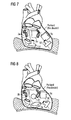
- FIGS. 7 to 12 each show advantageous possibilities for using a cable connector in cooperation with two heart support pumps, each having a projecting into the left or right ventricle heart stump.
- the cable connector is advantageously connected in each case with supply cables of the two pumps, which are connected to the cable connector by means of plug connections.
- the cable connector can advantageously be arranged directly on the heart, for example in contact with the pericardium, advantageously also inside the pericardial sac. This is particularly beneficial if the heart is already reduced by a dysfunction.
- the cable connector can advantageously be fastened to the pericardial sac, for example sewn thereto.
- the cable connector should have a sufficient distance to the cardiac assistance pumps.
Abstract
Die Erfindung bezieht sich auf eine implantierbare Kabelverbindungseinrichtung mit einem Kabelverbinder (2), der zwei oder mehr Steckverbindungselemente (8, 9, 10) aufweist, mit denen je ein implantierbares Kabel durch eine Steckverbindung verbindbar ist, wobei der Kabelverbinder als steifer Körper aus einem biokompatiblen Material ausgebildet ist.The invention relates to an implantable cable connecting device with a cable connector (2) having two or more connector elements (8, 9, 10), with each of which an implantable cable is connectable by a plug connection, wherein the cable connector as a rigid body of a biocompatible Material is formed.
Description
Die Erfindung liegt auf dem Gebiet der Mechanik und Elektrotechnik und ist mit besonderem Vorteil in der Medizintechnik anwendbar. Die Erfindung bezieht sich speziell auf eine Kabelverbindungseinrichtung, die implantierbar ist.The invention is in the field of mechanics and electrical engineering and is particularly applicable in medical technology. The invention particularly relates to a cable connection device which is implantable.
In der Medizintechnik sind unterschiedliche aktive Implantate üblich, die teilweise Körperteile ersetzen oder ergänzen. Sie beinhalten oft Sensoren oder Aktoren und können mechanische oder elektrische Funktionsweisen realisieren. Viele solche Implantate sind mit elektrischen Einrichtungen, beispielsweise Sensoren oder auch Motoren oder Steuerungseinrichtungen, versehen, die, beispielsweise zum Zweck der Energieversorgung oder der Kommunikation, mittels perkutaner Kabel mit dem Bereich außerhalb des Patientenkörpers, in den sie implantiert sind, verbunden werden sollen.In medical technology, different active implants are common, some of which replace or supplement body parts. They often contain sensors or actuators and can realize mechanical or electrical functions. Many such implants are provided with electrical devices, such as sensors or motors or controls, which, for example, for power or communication purposes, are to be connected by percutaneous cables to the area outside the patient's body into which they are implanted.
Derartige perkutane Kabel, d. h, Kabel, die in einem Bereich ihres Verlaufs innerhalb des Patientenkörpers und in einem anderen Bereich ihres Verlaufs außerhalb des Patientenkörpers angeordnet sind, stellen grundsätzlich ein Risiko für Infektionen und Entzündungen dar. Es ist daher wünschenswert, dass beim Eintreten von Komplikationen ein entsprechendes Kabel in einfacher Weise entfernt und/oder ausgetauscht werden kann. Zu diesem Zweck ist es grundsätzlich bekannt, innerhalb des Körpers eines Patienten bei einem implantierbaren Kabel eine Steckverbindung vorzusehen.Such percutaneous cables, d. In general, cables located in a region of their course within the patient's body and in another area of their course outside the patient's body present a risk of infection and inflammation. It is therefore desirable to have a corresponding cable in the event of complications can be easily removed and / or replaced. For this purpose, it is generally known to provide a connector within the body of a patient with an implantable cable.
Aus der internationalen Patentanmeldung
Der vorliegenden Erfindung liegt vor dem Hintergrund des Standes der Technik die Aufgabe zugrunde, einen implantierbaren Kabelverbinder zu schaffen, der besonders einfach und stabil aufgebaut ist und bei der Implantation und der Herstellung der Steckverbindungen besonders einfach zu handhaben ist.The present invention is based on the background of the prior art, the object to provide an implantable cable connector, which is particularly simple and stable and is particularly easy to handle in the implantation and the production of the connectors.
Die Aufgabe wird mit den Merkmalen der Erfindung gemäß Patentanspruch 1 gelöst.The object is achieved with the features of the invention according to claim 1.
Die Erfindung bezieht sich dabei auf eine implantierbare Kabelverbindungseinrichtung mit einem Kabelverbinder, der zwei oder mehr Steckverbindungselemente aufweist, mit denen je ein implantierbares Kabel durch eine Steckverbindung verbindbar ist, wobei der Kabelverbinder als steifer Körper aus einem biokompatiblen Material ausgebildet ist.The invention relates to an implantable cable connection device with a cable connector having two or more connector elements, with each of which an implantable cable is connectable by a plug connection, wherein the cable connector is formed as a rigid body made of a biocompatible material.
Durch die Anordnung mehrerer Steckverbindungselemente an dem Kabelverbinder ist es möglich, diesen vollständig zu implantieren und sowohl ein perkutanes Kabel, das die Verbindung von dem Kabelverbinder zum Körper-äußeren herstellt, als auch ein weiteres, vollständig implantiertes Kabel und gegebenenfalls weitere, insbesondere ebenfalls vollständig implantierte Kabel an den Kabelverbinder anzuschließen. Dadurch, dass dieser als steifer Körper ausgebildet ist, liegen die Eingangs- und Abgangsrichtungen der Steckverbindungselemente zuverlässig fest, und zum Herstellen und Lösen der Steckverbindungen ist es lediglich notwendig, den Kabelverbinder kurzfristig oder dauerhaft zu fixieren. Der Kabelverbinder kann sich nicht im Gebrauch verformen, und hierdurch ist auch verhindert oder erschwert, dass die eingesteckten Kabel durch eine Verformung des Kabelverbinders in eine ungewollte Position gebracht werden. Zudem ist der Kabelverbinders als steifer Körper sehr kompakt herstellbar und leicht in einem Patientenkörper unterzubringen.By arranging a plurality of connector elements on the cable connector, it is possible to completely implant this and both a Percutaneous cable that makes the connection from the cable connector to the body-outer, as well as another, fully implanted cable and possibly other, in particular also completely implanted cable to the cable connector to connect. The fact that this is designed as a rigid body, the input and output directions of the connector elements are reliably fixed, and for the manufacture and release of the connectors, it is only necessary to fix the cable connector short-term or permanent. The cable connector can not deform in use, and thereby also prevents or impedes that the inserted cables are brought by an deformation of the cable connector in an unwanted position. In addition, the cable connector as a rigid body is very compact to produce and easy to accommodate in a patient's body.
Eine besonders vorteilhafte Ausgestaltung der Erfindung sieht vor, dass mindestens zwei, insbesondere drei oder mehr Steckverbindungselemente auf derselben Seite des Kabelverbinders angeordnet sind. Durch diese Geometrie lassen sich mehrere Kabel an die Steckverbindungselemente des Kabelverbinders anstecken, wie es anatomisch günstig ist, insbesondere ohne diesen drehen zu müssen. Dies ist insbesondere dann wichtig, wenn Kabel nach dem Einsetzen des Kabelverbinders in den Patientenkörper gesteckt werden müssen, beispielsweise auch bei der Auswechslung von defekten Kabeln.A particularly advantageous embodiment of the invention provides that at least two, in particular three or more connector elements are arranged on the same side of the cable connector. Through this geometry, several cables can be plugged into the connector elements of the cable connector, as it is anatomically favorable, especially without having to turn this. This is particularly important when cables have to be inserted after insertion of the cable connector in the patient's body, for example, in the replacement of defective cables.
Eine weitere vorteilhafte Ausgestaltung der Erfindung sieht vor, dass alle Steckverbindungselemente auf derselben Seite des Kabelverbinders angeordnet sind. Bei dieser Ausgestaltung des Kabelverbinders kann dieser so implantiert werden, dass die Steckverbindungselemente jeweils auf der Seite des Kabelverbinders liegen, die durch einen minimalen Eingriff durch eine minimale Öffnung des Patientenkörpers leicht von außen zu erreichen sind. Der Kabelverbinder selbst muss dann zum Auswechseln der Steckverbindungen nicht dem Patientenkörper entnommen werden. Die Steckverbindungselemente können vorteilhaft an den kleinsten oder schmalsten der Seitenflächen des Kabelverbinders angeordnet sein.A further advantageous embodiment of the invention provides that all plug connection elements are arranged on the same side of the cable connector. In this embodiment, the cable connector, this can be implanted so that the connector elements are each on the side of the cable connector, which can be easily reached from the outside by a minimal intervention by a minimum opening of the patient's body. The cable connector itself must then not be removed from the patient's body to replace the connectors. The plug connection elements can advantageously be arranged on the smallest or narrowest of the side surfaces of the cable connector.
Die Erfindung kann außerdem vorteilhaft dadurch ausgestaltet werden, dass die Steckachsen der Steckverbindungselemente, die gemeinsam auf einer Seite des Kabelverbinders angeordnet sind, parallel zueinander ausgerichtet sind. Auch durch eine parallele, insbesondere steife Anordnung der Steckachsen der Steckverbindungselemente an dem Kabelverbinder lässt sich die Handhabung der Steckverbindungen vereinfachen. Unter den Steckachsen der Steckverbindungselemente wird jeweils die Richtung verstanden, in der ein Kabel mit dem jeweils komplementären Steckverbindungselement auf das an dem Kabelverbinder angeordnete Steckverbindungselement aufgesteckt wird. Bei gängigen hermaphrodisischen Steckverbindungen ist die Steckachse parallel zur Längsachse der Steckerstifte bzw. der entsprechenden Buchsen.The invention can also be advantageously configured in that the plug-in axes of the connector elements, which are arranged together on one side of the cable connector, are aligned parallel to each other. Also, by a parallel, in particular rigid arrangement of the plug-in axes of the connector elements on the cable connector, the handling of the connectors can be simplified. Under the plug-in axes of the connector elements is in each case understood the direction in which a cable is plugged with the respective complementary connector element on the cable connector arranged on the connector element. In common hermaphrodisiac connectors, the plug-in axis is parallel to the longitudinal axis of the connector pins or the corresponding sockets.
Eine parallele Ausrichtung der Steckachsen der Steckverbindungselemente führt auch dazu, dass diese mit minimalem Abstand zueinander ausgeführt werden können und dass die entsprechenden komplementären Steckverbindungselemente von Kabeln in gleicher Weise mit minimalem Abstand zueinander außerhalb des Kabelverbinders angeordnet werden können. Der insgesamt verwendete und benötigte Bauraum der Kabelverbindungseinrichtung wird somit minimiert.A parallel orientation of the stub axles of the connector elements also means that they can be performed with minimal distance from each other and that the corresponding complementary connector elements of cables can be arranged in the same way with minimum distance from each other outside of the cable connector. The overall space required and required space of the cable connection device is thus minimized.
In besonders vorteilhafter Form wird die Erfindung außerdem dadurch verwirklicht, dass der Kabelverbinder eine als ebene Fläche ausgebildete Seite aufweist, an der die Steckverbindungselemente angeordnet sind, und dass alle übrigen Begrenzungsflächen des Kabelverbinders konvex gerundet sind. Ein derartiger, weitgehend an seinen Außenseiten abgerundet ausgeführter Kabelverbinder lässt sich ohne weiteres, insbesondere ohne die Gefahr von besonderen Gewebebelastungen in den abgerundeten Bereichen des Kabelverbinders, in einen Patientenkörper implantieren. Auch bei einer Bewegung des Gewebes, in das der Kabelverbinder eingebettet ist, sind keine Verletzungen zu befürchten.In a particularly advantageous form, the invention is also realized in that the cable connector has a flat surface formed side on which the connector elements are arranged, and that all other boundary surfaces of the cable connector are convex rounded. Such a cable connector, which is largely rounded off on its outer sides, can be readily implanted in a patient's body, in particular without the risk of special tissue loads in the rounded regions of the cable connector. Even with a movement of the tissue in which the cable connector is embedded, no injuries are to be feared.
Es kann außerdem vorteilhaft vorgesehen sein, dass der Kabelverbinder im Wesentlichen halbkugelförmig abgerundet ausgebildet ist. Außer einer Halbkugel kann der Kabelverbinder auch die Form eines halbierten ellipsoiden oder eines anderen abgerundeten Körpers annehmen.It can also be advantageously provided that the cable connector is formed substantially hemispherical rounded. Apart from a hemisphere, the cable connector may also take the form of a halved ellipsoidal or other rounded body.
Besonders vorteilhaft ist auch eine flache Form des Kabelverbinders, bei der die Länge und Breite ein Mehrfaches der Höhe betragen, wobei die Ecken und Kanten abgerundet sind. Dabei kann die Grundform die eines Quaders sein.Also particularly advantageous is a flat shape of the cable connector, in which the length and width amount to a multiple of the height, wherein the corners and edges are rounded. The basic form may be that of a cuboid.
Eine weitere vorteilhafte Ausgestaltung der Erfindung sieht vor, dass der Kabelverbinder als Gehäuse mit wenigstens einem Innenraum ausgebildet ist. Ein als kompakter Körper hergestellter Kabelverbinder kann einerseits durch die günstige interne Führung von Leitungen auf kleinem Raum die verschiedenen Steckverbindungselemente miteinander verbinden und zudem noch einen Innenraum aufweisen, in dem vorteilhaft beispielsweise ein elektrischer Energiespeicher/Akkumulator oder ein elektrisch aktives Element, beispielsweise ein elektrischer Schaltkreis, insbesondere eine Einrichtung zur drahtlosen Kommunikation, angeordnet sein kann. Beispielsweise kann in dem Kabelverbinder auch ein Transponder angeordnet sein, der eine Identifikation erlaubt, ohne dass eine Energieversorgung notwendig ist (radio-tag). Der Innenraum kann mit einem Kleber, einer Vergussmasse oder einem Fluid gefüllt sein, es kann jedoch auch ein Hohlraum frei bleiben.A further advantageous embodiment of the invention provides that the cable connector is designed as a housing with at least one interior. A cable connector produced as a compact body can on the one hand connect the various plug connection elements to one another by means of the favorable internal guidance of lines in a small space and furthermore also have an interior in which, for example, an electrical energy storage / accumulator or an electrically active element, for example an electrical circuit, In particular, a device for wireless communication, can be arranged. For example, in the cable connector, a transponder can be arranged, which allows identification without a power supply is necessary (radio-tag). The interior can be filled with an adhesive, a potting compound or a fluid, but it can also remain a cavity free.
In dem Innenraum kann beispielsweise auch eine Steuereinrichtung für einen oder mehrere Blutpumpenmotoren angeordnet sein. Dazu kann dort ein Mikrocontroller oder eine andere programmierbare Einrichtung vorgesehen sein.In the interior, for example, a control device for one or more blood pump motors may be arranged. For this purpose, a microcontroller or another programmable device can be provided there.
Um eine besonders gewebeverträgliche Ausführungsform der Erfindung zu schaffen, kann zudem vorgesehen sein, dass der Kabelverbinder an seinen Außenseiten ausschließlich aus Metall und/oder Glas und/oder Keramik besteht. Diese Materialien sind in höchstem Maße biokompatibel, d. h. gewebeverträglich, und langzeitstabil, so dass ein aus einem solchen Material bestehender Kabelverbinder langzeitimplantierbar ist. Die Außenflächen sind vorteilhaft glatt gestaltet.In order to create a particularly tissue-compatible embodiment of the invention, it can also be provided that the cable connector consists exclusively of metal and / or glass and / or ceramic on its outer sides. These materials are highly biocompatible, i. H. tissue-compatible, and long-term stability, so that an existing of such a material cable connector is long-term implantable. The outer surfaces are advantageously designed smooth.
Als Metall kommt in diesem Zusammenhang besonders vorteilhaft Titan in Frage. Das Gehäuse des Kabelverbinders kann dabei auch aus mehreren Teilen bestehen, die zur Außenseite des Kabelverbinders gasdicht zusammengefügt, insbesondere miteinander verschweißt, verklebt oder vergossen sind. Beispielsweise kann ein Metallelement des Kabelverbinders mit einem Glasteil verschmolzen sein. Der Glasteil kann seinerseits wieder mit einer Keramik gasdicht verschmolzen sein. Ein Metall kann auch mit einer Keramik oder einem Glas mittels einer Metalllötung gasdicht verbunden werden. All diesen Verbindungstechniken ist gemein, dass sie eine zuverlässige Fixierung bei gleichzeitiger gasdichter Abdichtung und chemischer sowie physikalischer Festigkeit verbinden.As metal comes in this context particularly advantageous titanium in question. The housing of the cable connector can also consist of several parts, which are joined gas-tight to the outside of the cable connector, in particular welded together, glued or potted. For example, a metal element of the cable connector with a glass part be merged. The glass part can in turn be sealed gas-tight with a ceramic. A metal can also be gas-tightly connected to a ceramic or a glass by means of a metal brazing. All these joining techniques have in common that they combine a reliable fixation with simultaneous gas-tight sealing and chemical and physical strength.
Ein Kabelverbinder kann beispielsweise, wenn er zusammen mit einer oder mehreren herzunterstützenden Blutpumpen verwendet wird, im Zwischenraum zwischen dem dann üblicherweise etwas verkleinerten Herzmuskel und dem Herzbeutel untergebracht werden. Es ist auch eine subkutane Anordnung des Kabelverbinders möglich, und es können an diesem beispielsweise Ösen zum Vernähen am Körpergewebe vorgesehen sein.For example, a cable connector, when used in conjunction with one or more cardiac assistive blood pumps, may be placed in the space between the then-usually somewhat-reduced heart muscle and pericardium. It is also a subcutaneous arrangement of the cable connector possible, and it can be provided on this example, eyelets for sewing on the body tissue.
Die Erfindung bezieht sich zudem auf eine Kabelverbindungseinrichtung mit einem Kabelverbinder, einem in diesen eingesteckten ersten perkutanen Kabel und wenigstens einem in den Kabelverbinder eingesteckten zweiten Kabel sowie einem mit dem zweiten Kabel verbundenen Implantat, insbesondere einer Blutpumpe. Zudem kann optional noch ein mit dem Kabelverbinder durch eine Steckverbindung verbundenes drittes Kabel sowie ein mit diesem dritten Kabel verbundenes weiteres Implantat, insbesondere ebenfalls eine implantierte Blutpumpe, vorgesehen sein.The invention also relates to a cable connection device with a cable connector, a first percutaneous cable inserted therein and at least one second cable inserted into the cable connector and an implant connected to the second cable, in particular a blood pump. In addition, optionally, a third cable connected to the cable connector by a plug connection and a further implant connected to this third cable, in particular also an implanted blood pump, may be provided.
Die Kabelverbindungseinrichtung kann also potenziell nicht nur den Kabelverbinder mit Steckverbindungseinrichtungen umfassen, sondern auch die entsprechenden in diesen eingesteckten Kabel und mit diesen verbundene Blutpumpen oder alternative Implantate. Auch ein eingestecktes perkutanes Kabel, das mit dem Kabelverbinder verbunden ist, kann zu der Kabelverbindungseinrichtung gehören.Thus, the cable connection device may potentially include not only the cable connector with connector devices, but also the corresponding cables inserted therein and blood pumps or alternative implants connected thereto. Also, an inserted percutaneous cable connected to the cable connector may be part of the cable connection device.
Die Kabelverbindungseinrichtung kann somit insgesamt ein System aus mehreren Implantaten, insbesondere Pumpen, umfassen, die mittels Kabelverbindungen über einen Kabelverbinder mit einem perkutanen Kabel verbunden sind, das außerhalb des Patientenkörpers an einem Kabelanschluß einfach zugänglich ist.The cable connecting device may thus comprise a total of a system of a plurality of implants, in particular pumps, which are connected by means of cable connections via a cable connector with a percutaneous cable, which is easily accessible outside the patient's body to a cable connection.
Der Kabelverbinder, insbesondere sein Gehäuse, kann zudem wenigstens ein, insbesondere zwei Koppelelemente, beispielsweise Schraubengewinde, Bajonettaufnahmen oder Ähnliches für ein Fixierelement aufweisen, mittels dessen der Verbinder gut manipulierbar ist, besonders auch bei einem Kabelsteckvorgang.The cable connector, in particular its housing, can also have at least one, in particular two coupling elements, for example screw threads, bayonet receptacles or the like for a fixing element, by means of which the connector is easy to manipulate, especially in a cable plugging operation.
Eine vorteilhafte Ausgestaltung der Erfindung sieht zudem vor, dass an der Außenseite des Kabelverbinders wenigstens zwei Steckverbindungselemente nebeneinander vorgesehen sind und dass zudem eine Verriegelungseinrichtung vorgesehen ist, die, solange jeweils eine der Steckverbindungen gelöst ist, das Lösen der anderen Steckverbindung blockiert, wobei hierzu insbesondere ein Verriegelungselement vorgesehen ist, das zwei Abdeckelemente zur wenigstens teilweisen Abdeckung je einer Steckverbindung aufweist, wobei das Verriegelungselement zwischen zwei Endpositionen bewegbar ist und in jeder der Endpositionen jeweils eine Steckverbindung blockiert ist.An advantageous embodiment of the invention also provides that on the outside of the cable connector at least two connector elements are provided side by side and that in addition a locking device is provided which, as long as one of the connectors is released, the release of the other connector blocked, in which case in particular a Locking element is provided which has two cover elements for at least partial cover each of a plug connection, wherein the locking element between two end positions is movable and in each of the end positions in each case a plug connection is blocked.
Eine solche Verriegelungseinrichtung verhindert, dass unbeabsichtigt zwei Steckverbindungen an dem Kabelverbinder gleichzeitig gelöst werden, was dazu führen kann, dass beim Wiedereinstecken Kabel vertauscht werden. Dies ist insbesondere dann ungewollt und riskant, wenn zwei Kabelverbindungen zu zwei Blutpumpen gelöst werden, die in verschiedenen Teilen eines Patientenherzens oder an verschiedenen Stellen bezüglich des Herzens in dessen Peripherie oder allgemein im Blutkreislauf angeordnet sind, deren Vertauschung schädlich sein kann. Zusätzlich oder alternativ zu dieser Maßnahme kann auch eine mechanische Kodierung der Steckverbinder zu deren Unterscheidung vorgesehen sein.Such a locking device prevents inadvertent release of two connectors on the cable connector at the same time, which can lead to reversed cables when reinserting. This is particularly undesirable and risky when two cable connections are made to two blood pumps located in different parts of a patient's heart or at various locations with respect to the heart in the periphery or generally in the bloodstream, the exchange of which can be detrimental. In addition or as an alternative to this measure, it is also possible to provide a mechanical coding of the plug connectors for their differentiation.
Ein vorteilhaftes Verfahren zum Implantieren einer Kabelverbindungseinrichtung der erfindungsgemäßen Art kann außerdem vorsehen, dass der Kabelverbinder im Patientenkörper angeordnet und danach wenigstens ein, insbesondere zwei oder drei implantierbare Kabel mittels Steckverbindungen mit dem Kabelverbinder verbunden werden.An advantageous method for implanting a cable connection device of the type according to the invention can also provide that the cable connector is arranged in the patient's body and then at least one, in particular two or three implantable cables are connected to the cable connector by means of plug connections.
Weitere implantierbare Elemente, wie Blutpumpen, die mit dem Kabelverbinder verbunden werden sollen, können vorteilhaft schon vor der Implantation des Kabelverbinders oder auch nach der Implantation des Kabelverbinders implantiert werden, jedenfalls müssen sie nicht gleichzeitig mit dem Kabelverbinder eingebracht werden.Other implantable elements, such as blood pumps, which are to be connected to the cable connector can advantageously already before the implantation of the cable connector or after the implantation of the cable connector In any case, they do not have to be inserted simultaneously with the cable connector.
Die Erfindung bezieht sich auch auf ein Verfahren zum Austauschen mehrerer mit einem erfindungsgemäßen Kabelverbinder verbundener implantierbarer Kabel, bei dem zuerst die Steckverbindung eines ersten Kabels gelöst und ein neues erstes Kabel mit dem Kabelverbinder mittels der Steckverbindung verbunden wird und darauf die Steckverbindung eines zweiten Kabels gelöst und eine Steckverbindung des Kabelverbinders zu einem neuen zweiten Kabel hergestellt wird, wobei insbesondere das erste und das zweite Kabel mit je einer Blutpumpe verbunden sind. Durch ein derartiges Vorgehen wird die Vertauschung zweier Kabel und/oder Steckverbindungen verhindert.The invention also relates to a method for exchanging a plurality of implantable cables connected to a cable connector according to the invention, in which first the plug connection of a first cable is released and a new first cable is connected to the cable connector by means of the plug connection and the plug connection of a second cable is released thereon a connector of the cable connector is made to a new second cable, wherein in particular the first and the second cable are each connected to a blood pump. By doing so, the interchange of two cables and / or connectors is prevented.
Außerdem bezieht sich die Verbindung auch auf ein Verfahren zum Austauschen eines mit einem erfindungsgemäßen Kabelverbinder verbundenen implantierten Kabels, bei dem zuerst mit einem Koppelelement des Kabelverbinders ein Haltewerkzeug verbunden, darauf die Steckverbindung des Kabels gelöst und ein neues Kabel mittels einer Steckverbindung mit dem Kabelverbinder verbunden wird. Auf diese Weise kann der Kabelverbinder als steifer Körper problemlos von außen festgehalten werden, während Steckverbindungen gelöst oder gesteckt werden. Der Kabelverbinder kann dabei implantiert bleiben, und er kommt nur minimal mit körperfremden Instrumenten in Kontakt.In addition, the connection also relates to a method for exchanging an implanted cable connected to a cable connector according to the invention, in which first a holding tool is connected to a coupling element of the cable connector, then the plug connection of the cable is released and a new cable is connected to the cable connector by means of a plug connection , In this way, the cable connector can be easily held as a rigid body from the outside, while connectors are dissolved or plugged. The cable connector can remain implanted, and it comes only minimally in contact with alien instruments.
Ein Koppelelement kann grundsätzlich eine mechanische Passung aufweisen, wie ein Schraubengewinde oder einen Bajonettverschluss, oder es kann beispielsweise durch einen an dem Kabelverbinder und/oder einem Haltewerkzeug befestigten Magneten auch magnetisch ausgebildet sein.A coupling element may in principle have a mechanical fit, such as a screw thread or a bayonet closure, or it may also be formed magnetically, for example, by a magnet attached to the cable connector and / or a holding tool.
Eine vorteilhafte Verwendung der Kabelverbindungseinrichtung sieht vor, dass die Kabelverbindungseinrichtung mit zwei Herzunterstützungspumpen verbunden und gemeinsam mit diesen unmittelbar an einem Herzen angeordnet, insbesondere an diesem oder am Herzbeutel fixiert ist.An advantageous use of the cable connection device provides that the cable connection device is connected to two heart support pumps and arranged together with these directly on a heart, in particular fixed on this or on the pericardium.
Ein vorteilhaftes Verfahren zum Implantieren einer Kabelverbindungseinrichtung sieht vor, dass der Kabelverbinders mit zwei Herzunterstützungspumpen elektrisch verbunden und zeitlich vorher oder danach am Herzbeutel eines Patientenherzens fixiert wird.An advantageous method for implanting a cable connecting device provides that the cable connector with two heart support pumps is electrically connected and temporally before or after the pericardium of a patient's heart is fixed.
Im Folgenden wird die Erfindung anhand eines Ausführungsbeispiels in einer Zeichnung gezeigt und nachfolgend beschrieben. Dabei zeigt
- Fig. 1
- in einer Übersichtsdarstellung eine Kabelverbindungseinrichtung mit zwei Blutpumpen und einem perkutanen Kabel im implantierten Zustand,
- Fig. 2
- einen Kabelverbinder im Querschnitt mit drei Steckverbindungselementen,
- Fig. 3
- einen Kabelverbinder im Querschnitt mit zwei Steckverbindungselementen und einer ebenen Frontfläche,
- Fig. 4
- einen Kabelverbinder mit einer gekrümmten Frontfläche und zwei Steckverbindungselementen,
- Fig. 5
- einen Kabelverbinder mit detaillierterer Darstellung der internen Leiterführung,
- Fig. 6
- eine Verriegelungseinrichtung für zwei Steckverbindungen an einem Kabelverbinder, sowie
- Fig.7 bis Fig. 12
- verschiedene Szenarien zur Platzierung von jeweils zwei Herzunterstützungspumpen für die Herzventrikel und einen Kabelverbinder.
- Fig. 1
- in an overview, a cable connection device with two blood pumps and a percutaneous cable in the implanted state,
- Fig. 2
- a cable connector in cross section with three connector elements,
- Fig. 3
- a cable connector in cross section with two connector elements and a flat front surface,
- Fig. 4
- a cable connector with a curved front surface and two connector elements,
- Fig. 5
- a cable connector with a more detailed representation of the internal conductor guide,
- Fig. 6
- a locking device for two connectors on a cable connector, as well
- 7 to FIG. 12
- various scenarios for the placement of two cardiac ventricular assistive pumps each and a cable connector.
Der Begriff "perkutanes Kabel" bezeichnet üblicherweise ein Kabel, das die Haut oder einen anderen Teil der Begrenzungsfläche zwischen dem Patientenkörper und der Außenwelt durchdringt. Im Zusammenhang mit der vorliegenden Erfindung kann ein perkutanes Kabel jedoch auch ein implantierbares Kabel bezeichnen, das vollständig innerhalb des Patientenkörpers verläuft und an einer Anschlusseinrichtung endet, mit der ein außerhalb des Patientenkörpers weiterführendes Kabel beispielsweise induktiv durch die Haut koppelbar ist. Es kann auch vorgesehen sein, dass nur ein Steckanschluss 3a des perkutanen Kabels in die Haut eingelassen ist und diese durchdringt.The term "percutaneous cable" usually refers to a cable that penetrates the skin or other part of the boundary surface between the patient's body and the outside world. However, in the context of the present invention, a percutaneous cable may also refer to an implantable cable that extends completely within the patient's body and terminates at a terminal device with which a cable extending outside of the patient's body can, for example, be inductively coupled through the skin. It can also be provided that only one
An den Kabelverbinder 2 ist außer dem perkutanen Kabel 3 ein zweites implantierbares Kabel 4 angeschlossen, das den Kabelverbinder 2 mit einer ersten Blutpumpe 5 verbindet. Ein drittes implantiertes Kabel 6 ist mit dem Kabelverbinder 2 einerseits und einer zweiten Blutpumpe 7 andererseits verbunden. Die implantierten Kabel 3, 4, 6 sind mit dem Kabelverbinder 2 jeweils über Steckverbindungen elektrisch leitend verbunden. Vorteilhaft sind die implantierten Kabel an ihren dem Kabelverbinder 2 abgewandten Enden mittels je eines weiteren Steckverbinders 3a jeweils mit einem weiteren Element, beispielsweise mit den Blutpumpen 5, 7 verbunden. Die implantierten Kabel 4, 6 können jedoch mit den jeweiligen Blutpumpen 5, 7 auch dauerhaft und unlösbar verbunden sein.In addition to the percutaneous cable 3, a second implantable cable 4, which connects the
Da mittels des Kabelverbinders 2 mehrere implantierte Elemente, im dargestellten Beispiel die beiden Blutpumpen 5, 7, über ein einziges, perkutanes Kabel 3 von außerhalb des Patientenkörpers ansteuerbar sind, wird der für die Durchführung eines Kabels benötigte Bereich der Haut, der geöffnet wird und dauerhaft von einem Fremdkörper durchsetzt ist, minimiert. Eine besonders vorteilhafte Ausgestaltung ergibt sich dadurch, dass das perkutane Kabel 3 im Querschnitt kreisrund ausgeführt ist, um die Berührungsfläche zwischen dem Kabel und der Haut des Patientenkörpers insgesamt und speziell an der Durchtrittsstelle durch die Haut zu minimieren.Since by means of the cable connector 2 a plurality of implanted elements, in the example shown, the two blood pumps 5, 7, via a single, percutaneous cable 3 can be controlled from outside the patient's body, required for the implementation of a cable portion of the skin, which is opened and permanently is traversed by a foreign body, minimized. A particularly advantageous embodiment results from the fact that the percutaneous cable 3 is circular in cross-section, in order to minimize the contact area between the cable and the skin of the patient's body as a whole and especially at the point of penetration through the skin.
Der auf den Metallzylinder 11 am Kabelverbinder 2 aufgesteckte Stecker 17 weist Steckerhülsen 18 auf, die auf die Steckerstifte 12, 13 aufsteckbar sind, um einen galvanischen Kontakt zu diesen herzustellen. Die Steckerhülsen 18 sind ihrerseits mit Leitern verbunden, die innerhalb des Steckers 17 zu dem angeschlossenen implantierten Kabel geführt sind. Es ist ein Steckergehäuse 19 vorgesehen, das eine Form aufweist, die dem Zylinder 11 entspricht und die auf den Zylinder 11 aufsteckbar ist. Dabei ist in dem Steckergehäuse 19 in einer innen umlaufenden Nut ein O-Ring 20 aus einem Elastomer vorgesehen, der an dem Metallzylinder 11 außen fluiddicht dichtet.Plugged onto the
Zudem kann eine Sicherung vorgesehen sein, die den Stecker 17 an dem Kabelverbinder 2 festhält, beispielsweise durch eine Überwurfmutter, die an dem Kabelverbinder 2 verschraubbar ist, oder durch eine Bajonettverbindung zwischen dem Stecker 17 und dem Metallzylinder 11.In addition, a fuse may be provided which holds the
Der Gehäuseteil des Kabelverbinders 2, der sich an die ebene Frontplatte anschließt, welche die ebene Frontfläche 21 bildet, ist beispielsweise als Kugelkalotte oder als Teil eines Rotationsellipsoids ausgebildet und besteht beispielsweise aus Metall, insbesondere Titan, oder einer Keramik. Die Verbindungen zwischen dem Metall und der Keramik können durch Aufschmelzen des Metalls oder durch Zwischenlagern eines Glaslots oder Metalllots fluiddicht ausgeführt werden. Es ist auch eine fluiddichte Verpressung der Elemente durch Druckanwendung denkbar.The housing part of the
In
In
Mit der Leiterplatte 26 kann über Steckerstifte auch eine elektronische Einrichtung 28 verbunden sein, die der drahtlosen Kommunikation zwischen Implantaten, die an den Kabelverbinder angeschlossen sind, und einer Einrichtung außerhalb des Patientenkörpers dient, Zu diesem Zweck ist die elektronische Einrichtung 28 mit einer Antenne 29 innerhalb des Kabelverbinders bzw. eines Hohlraums im Kabelverbinder 2 versehen.An
Die erfindungsgemäße Kabelverbindungseinrichtung mit einem Kabelverbinder und entsprechenden implantierten Kabeln sowie gegebenenfalls an diese angeschlossenen implantierten Blutpumpen oder anderen Elementen dient dem sicheren Betrieb der Implantate, wobei beim Auftreten von Fehlern in der Anschlusstechnik in einfacher Weise Kabel ersetzt werden können, ohne dass implantierte, an die Kabel angeschlossene Elemente notwendigerweise entfernt bzw. ersetzt werden müssen.The cable connecting device according to the invention with a cable connector and corresponding implanted cables and optionally connected to these implanted blood pumps or other elements is used for safe operation of the implants, which can easily be replaced in case of errors in the connection technology cables without implanted, to the cable connected elements must necessarily be removed or replaced.
In der Figur ist für die Steckverbindungselemente 35, 36 ein Verriegelungselement 39 dargestellt, das zwei Abdeckelemente 40, 41 aufweist, von denen das Abdeckelement 40 das Steckverbindungselement 36 in der gezeigten Stellung abdeckt und damit blockiert, indem es ein Anfassen/Drehen eines aufgesteckten Kabelsteckers verhindert. Wird das Verriegelungselement 39 nach links in Richtung des Pfeils 42 verschoben, so deckt das Abdeckelement 41 das Steckverbindungselement 35 ab. Somit ist, wenn das Verriegelungselement 39 zwischen den Endpositionen verschoben wird, jeweils eines der Steckverbindungselemente 35, 36 blockiert, so dass zumindest nicht unbeabsichtigt beide Steckverbindungen gelöst werden. Das Verriegelungselement kann beispielsweise in einer Führung auf dem Kabelverbinder 2 verschiebbar geführt sein.In the figure, a locking
In
Alternativ oder zusätzlich zu einer Verriegelungseinrichtung der oben beschriebenen Art kann auch ein Bussystem vorgesehen sein, das die Adressierung eines bestimmten, über ein Kabel an den Kabelverbinder angeschlossenen Implantats, insbesondere einer Blutpumpe, unabhängig davon ermöglicht, in welches Steckverbindungselement am Kabelverbinder das Kabel eingesteckt ist.Alternatively, or in addition to a locking device of the type described above, a bus system may be provided which allows the addressing of a particular, connected via a cable to the cable connector implant, in particular a blood pump, regardless of which plug connector element on the cable connector, the cable is inserted.
Zusätzlich zu oder anstelle des Kabels 3, das perkutan ausgebildet und mit dem Kabelverbinder 2 verbunden ist, kann noch ein weiteres implantiertes Kabel mit dem Kabelverbinders 2 mittels einer Steckverbindung verbunden sein, das andererseits mit einem Energieversorgungs- oder Kommunikationsmodul verbunden ist, welches direkt unter der Haut eines Patienten angeordnet ist und perkutan über Felder und/oder Wellen eine Energie- oder Informationsübertragung erlaubt. Grundsätzlich kann jedes an dem Kabelverbinder angeschlossene Kabel an seinem dem Kabelverbinder abgewandten Ende mit einem oder mehreren parallelen weiterführenden Kabeln im Sinne einer Kaskadierung verbunden sein.In addition to or instead of the cable 3, which is percutaneously formed and connected to the
Die Kabelverbindungseinrichtung, die, wie in
- Perkutanes Kabel: 100 bis 160 cm Länge; erstes implantierbares Verbindungskabel zu einem Implantat: 20
bis 40 cm Länge; sowie zweites implantierbares Verbindungskabel zu einem weiteren Implantat: 20bis 40 cm.
- Percutaneous cable: 100 to 160 cm in length; first implantable connection cable to an implant: 20 to 40 cm in length; and second implantable connection cable to another implant: 20 to 40 cm.
Die
Der Kabelverbinder kann vorteilhaft unmittelbar am Herzen, beispielsweise im Kontakt mit dem Herzbeutel, vorteilhaft auch innerhalb des Herzbeutels, angeordnet sein. Dies ist besonders dann günstig, wenn das Herz ohnehin durch eine Dysfunktion verkleinert ist.The cable connector can advantageously be arranged directly on the heart, for example in contact with the pericardium, advantageously also inside the pericardial sac. This is particularly beneficial if the heart is already reduced by a dysfunction.
Weiter kann der Kabelverbinder vorteilhaft am Herzbeutel befestigt, beispielsweise an diesem festgenäht sein.Furthermore, the cable connector can advantageously be fastened to the pericardial sac, for example sewn thereto.
Der Kabelverbinder sollte dabei einen ausreichenden Abstand zu den Herzunterstützungspumpen aufweisen.The cable connector should have a sufficient distance to the cardiac assistance pumps.
Im Folgenden sind verschiedene Möglichkeiten für eine optimierte Platzierung des Kabelverbinders in Abhängigkeit von der Position der Herzunterstützungspumpen aufgezeigt, entsprechend den Darstellungen der
-
Figur 7 : Platzierung Kabelverbinder und BVAD (Herzunterstützungspumpen für beide Ventrikel): Szenario 1- 1. LVAD (left ventricular assist device): Einlass-Stutzen der Pumpe in Apex des linken Ventrikels (LV)
- 2. RVAD (right ventricular assist device): Einlass-Stutzen in inferiorer (diaphragmaler) Wand des rechten Ventrikels (RV)
- 3. Kabelverbinder wird positioniert:
- a) Zwischen rechtem Vorhof (RA) und Perikard (Herzbeutel)
- b) Zwischen anteriorer (freier) Wand des RV und Brustbein (Sternum)
- c) Zwischen lateraler Wand des LV und Perikard.
-
Figur 8 : Platzierung Kabelverbinder und BVAD:Szenario 2- 1. LVAD: Einlass-Stutzen der Pumpe 50 in Apex des linken Ventrikels (LV)
- 2. RVAD: Einlass-Stutzen der Pumpe 51 in anteriorer (freier) Wand des rechten Ventrikels (RV)
- 3. Kabelverbinder wird positioniert:
- a) Zwischen inferiorer (diaphragmaler) Wand des rechten Ventrikels (RV) und Pars diaphragmatica des Perikards
- b) Zwischen rechtem Vorhof (RA) und Perikard
- c) Zwischen lateraler Wand des LV und Perikard.
-
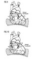
Figur 9 : Platzierung Kabelverbinder und BVAD: Szenario 3- 1. LVAD: Einlass-Stutzen der Pumpe in Apex des linken Ventrikels (LV)
- 2. RVAD: Einlass-Stutzen in rechtem Vorhof (RA)
- 3. Kabelverbinder wird positioniert:
- a) Zwischen inferiorer (diaphragmaler) Wand des rechten Ventrikels (RV) und Pars diaphragmatica des Perikards
- b) Zwischen anteriorer (freier) Wand des RV und Brustbein (Sternum)
- c) Zwischen lateraler Wand des LV und Perikard.
-
Figur 10 : Platzierung Kabelverbinder und BVAD: Szenario 4- 1. LVAD: Einlass-Stutzen der Pumpe in linkem Vorhof (LA)
- 2. RVAD: Einlass-Stutzen in inferiorer (diaphragmaler) Wand des rechten Ventrikels (RV)
- 3. Kabelverbinder wird positioniert:
- a) Zwischen rechtem Vorhof (RA) und Perikard
- b) Zwischen anteriorer (freier) Wand des RV und Brustbein (Sternum)
- c) Zwischen Apex des linken Ventrikels (LV) und Perikard.
-
Figur 11 : Platzierung Kabelverbinder und BVAD: Szenario 5- 1. LVAD: Einlass-Stutzen der Pumpe in linkem Vorhof (LA)
- 2. RVAD: Einlass-Stutzen in anteriorer (freier) Wand des rechten Ventrikels (RV)
- 3. Kabelverbinder wird positioniert:
- a) Zwischen rechtem Vorhof (RA) und Perikard
- b) Zwischen inferiorer (diaphragmaler) Wand des RV und Pars diaphragmatica des Perikards
- c) Zwischen Apex des linken Ventrikels (LV) und Perikard.
-
Figur 12 : Platzierung Kabelverbinder und BVAD: Szenario 6- 1. LVAD: Einlass-Stutzen der Pumpe in linkem Vorhof (LA)
- 2. RVAD: Einlass-Stutzen in rechtem Vorhof (RA)
- 3. Kabelverbinder wird positioniert:
- a) Zwischen anteriorer (freier) Wand des rechten Ventrikels (RV) und Brustbein (Sternum)
- b) Zwischen inferiorer (diaphragmaler) Wand des RV und Pars diaphragmatica des Perikards
- c) Zwischen Apex des linken Ventrikels (LV) und Perikard.
-
FIG. 7 : Placement of cable connector and BVAD (cardiac assist pump for both ventricles): Scenario 1- 1. LVAD (left ventricular assist device): inlet port of pump in apex of left ventricle (LV)
- 2. RVAD (right ventricular assist device): Inlet neck in inferior (diaphragm) wall of the right ventricle (RV)
- 3. Cable connector is positioned:
- a) Between right atrium (RA) and pericardium (pericardium)
- b) Between anterior (free) wall of the RV and sternum (sternum)
- c) Between the lateral wall of the LV and the pericardium.
-
FIG. 8 : Placement Cable Connector and BVAD:Scenario 2- 1. LVAD: pump 50 inlet port in left ventricular apex (LV)
- 2. RVAD:
Pump 51 inlet port in the anterior (free) wall of the right ventricle (RV) - 3. Cable connector is positioned:
- a) Between inferior (diaphragm) wall of the right ventricle (RV) and pars diaphragmatica of the pericardium
- b) Between right atrium (RA) and pericardium
- c) Between the lateral wall of the LV and the pericardium.
-
FIG. 9 : Placement Cable Connector and BVAD: Scenario 3- 1. LVAD: inlet port of pump in apex of left ventricle (LV)
- 2. RVAD: inlet nozzle in right atrium (RA)
- 3. Cable connector is positioned:
- a) Between inferior (diaphragm) wall of the right ventricle (RV) and pars diaphragmatica of the pericardium
- b) Between anterior (free) wall of the RV and sternum (sternum)
- c) Between the lateral wall of the LV and the pericardium.
-
FIG. 10 : Placement Cable Connector and BVAD: Scenario 4- 1. LVAD: inlet port of pump in left atrium (LA)
- 2. RVAD: inlet socket in inferior (diaphragm) wall of the right ventricle (RV)
- 3. Cable connector is positioned:
- a) Between right atrium (RA) and pericardium
- b) Between anterior (free) wall of the RV and sternum (sternum)
- c) Between the apex of the left ventricle (LV) and pericardium.
-
FIG. 11 : Placement Cable Connector and BVAD: Scenario 5- 1. LVAD: inlet port of pump in left atrium (LA)
- 2. RVAD: inlet socket in the anterior (free) wall of the right ventricle (RV)
- 3. Cable connector is positioned:
- a) Between right atrium (RA) and pericardium
- b) Between inferior (diaphragm) wall of the RV and pars diaphragmatica of the pericardium
- c) Between the apex of the left ventricle (LV) and pericardium.
-
FIG. 12 : Placement Cable Connector and BVAD: Scenario 6- 1. LVAD: inlet port of pump in left atrium (LA)
- 2. RVAD: inlet nozzle in right atrium (RA)
- 3. Cable connector is positioned:
- a) Between Anterior (Free) Wall of Right Ventricle (RV) and Sternum (Sternum)
- b) Between inferior (diaphragm) wall of the RV and pars diaphragmatica of the pericardium
- c) Between the apex of the left ventricle (LV) and pericardium.
Claims (13)
Priority Applications (4)
| Application Number | Priority Date | Filing Date | Title |
|---|---|---|---|
| EP13162255.7A EP2787581A1 (en) | 2013-04-04 | 2013-04-04 | Implantable cable connection device |
| DE112014001602.0T DE112014001602A5 (en) | 2013-04-04 | 2014-04-04 | Implantable cable connection device |
| US14/782,245 US20160030652A1 (en) | 2013-04-04 | 2014-04-04 | Implantable Cable-Connecting Device |
| PCT/EP2014/056775 WO2014161978A1 (en) | 2013-04-04 | 2014-04-04 | Implantable cable-connecting device |
Applications Claiming Priority (1)
| Application Number | Priority Date | Filing Date | Title |
|---|---|---|---|
| EP13162255.7A EP2787581A1 (en) | 2013-04-04 | 2013-04-04 | Implantable cable connection device |
Publications (1)
| Publication Number | Publication Date |
|---|---|
| EP2787581A1 true EP2787581A1 (en) | 2014-10-08 |
Family
ID=48092705
Family Applications (1)
| Application Number | Title | Priority Date | Filing Date |
|---|---|---|---|
| EP13162255.7A Withdrawn EP2787581A1 (en) | 2013-04-04 | 2013-04-04 | Implantable cable connection device |
Country Status (4)
| Country | Link |
|---|---|
| US (1) | US20160030652A1 (en) |
| EP (1) | EP2787581A1 (en) |
| DE (1) | DE112014001602A5 (en) |
| WO (1) | WO2014161978A1 (en) |
Cited By (1)
| Publication number | Priority date | Publication date | Assignee | Title |
|---|---|---|---|---|
| EP3936186A1 (en) * | 2020-07-07 | 2022-01-12 | Maxon International AG | Electrical connection for an actuator unit |
Families Citing this family (6)
| Publication number | Priority date | Publication date | Assignee | Title |
|---|---|---|---|---|
| DE102013208038B4 (en) | 2013-05-02 | 2016-09-08 | Michael Siegenthaler | Catheter-based cardiac assist system |
| EP3299044B1 (en) | 2016-09-22 | 2020-12-02 | Berlin Heart GmbH | Medical device |
| TWI590753B (en) * | 2016-11-02 | 2017-07-01 | 和碩聯合科技股份有限公司 | Pin protective cover and bi-directional optical sub-assemblies device using the same |
| EP3615104A1 (en) * | 2017-04-28 | 2020-03-04 | Tc1 Llc | Patient adapter for driveline cable and methods |
| DE102017213469A1 (en) * | 2017-08-03 | 2019-02-07 | Robert Bosch Gmbh | Device for connection to a cable of an implant and associated system |
| EP3922299A1 (en) * | 2020-06-11 | 2021-12-15 | Berlin Heart GmbH | Connection system for energy and / or data transmission from and / or to an implantable blood pump and cardiac assistance system |
Citations (4)
| Publication number | Priority date | Publication date | Assignee | Title |
|---|---|---|---|---|
| US20040034392A1 (en) * | 2002-08-16 | 2004-02-19 | Cardiac Pacemakers, Inc. | Connector module replacement for implantable medical stimulators |
| US20080208267A1 (en) * | 2007-02-26 | 2008-08-28 | Medtronic, Inc. | Implantable bifurcated neurostimulator adapters |
| US20110160516A1 (en) * | 2009-12-30 | 2011-06-30 | Thoratec Corporation | Mobility-Enhancing Blood Pump System |
| WO2011156391A2 (en) | 2010-06-07 | 2011-12-15 | Thoratec Corporation | Bi-ventricular percutaneous cable |
Family Cites Families (7)
| Publication number | Priority date | Publication date | Assignee | Title |
|---|---|---|---|---|
| US5366496A (en) * | 1993-04-01 | 1994-11-22 | Cardiac Pacemakers, Inc. | Subcutaneous shunted coil electrode |
| US6486407B1 (en) * | 2001-06-14 | 2002-11-26 | Trident Design Llc | Power strip with adjustable outlets |
| WO2007006080A1 (en) * | 2005-07-12 | 2007-01-18 | Ventracor Limited | Restraining device for a percutaneous lead assembly |
| US7347746B1 (en) * | 2006-10-27 | 2008-03-25 | Boston Scientific Neuromodulation Corporation | Receptacle connector assembly |
| US8162684B1 (en) * | 2008-08-07 | 2012-04-24 | Jerzy Roman Sochor | Implantable connector with contact-containing feedthrough pins |
| EP3025676B1 (en) * | 2007-10-11 | 2019-12-25 | Implantica Patent Ltd. | Implantable tissue connector |
| WO2012012552A1 (en) * | 2010-07-22 | 2012-01-26 | Thoratec Corporation | Controlling implanted blood pumps |
-
2013
- 2013-04-04 EP EP13162255.7A patent/EP2787581A1/en not_active Withdrawn
-
2014
- 2014-04-04 DE DE112014001602.0T patent/DE112014001602A5/en not_active Withdrawn
- 2014-04-04 WO PCT/EP2014/056775 patent/WO2014161978A1/en active Application Filing
- 2014-04-04 US US14/782,245 patent/US20160030652A1/en not_active Abandoned
Patent Citations (4)
| Publication number | Priority date | Publication date | Assignee | Title |
|---|---|---|---|---|
| US20040034392A1 (en) * | 2002-08-16 | 2004-02-19 | Cardiac Pacemakers, Inc. | Connector module replacement for implantable medical stimulators |
| US20080208267A1 (en) * | 2007-02-26 | 2008-08-28 | Medtronic, Inc. | Implantable bifurcated neurostimulator adapters |
| US20110160516A1 (en) * | 2009-12-30 | 2011-06-30 | Thoratec Corporation | Mobility-Enhancing Blood Pump System |
| WO2011156391A2 (en) | 2010-06-07 | 2011-12-15 | Thoratec Corporation | Bi-ventricular percutaneous cable |
Cited By (3)
| Publication number | Priority date | Publication date | Assignee | Title |
|---|---|---|---|---|
| EP3936186A1 (en) * | 2020-07-07 | 2022-01-12 | Maxon International AG | Electrical connection for an actuator unit |
| WO2022008178A1 (en) * | 2020-07-07 | 2022-01-13 | Maxon International Ag | Electrical connection for an actuator unit |
| EP4287419A3 (en) * | 2020-07-07 | 2024-02-14 | Maxon International AG | Electrical connection for an actuator unit |
Also Published As
| Publication number | Publication date |
|---|---|
| WO2014161978A1 (en) | 2014-10-09 |
| US20160030652A1 (en) | 2016-02-04 |
| DE112014001602A5 (en) | 2016-01-21 |
Similar Documents
| Publication | Publication Date | Title |
|---|---|---|
| WO2014161978A1 (en) | Implantable cable-connecting device | |
| EP2130566B1 (en) | Elongated implant with external energy coupling | |
| DE602004009585T2 (en) | Connecting pieces for connecting a line to an implantable medical device | |
| EP2111895B1 (en) | Connection housing for an electromedical implant | |
| DE69824425T2 (en) | CONNECTION SYSTEM FOR PACING PIPES | |
| DE60104428T2 (en) | JOINT PROSTHESIS | |
| DE102006018851A1 (en) | Active medical device implant with at least two diagnostic and / or therapeutic functions | |
| DE19818505A1 (en) | Medical lead adapter, method of making the same and making a quick electrical connection | |
| DE60114291T2 (en) | Device for implanting a cardiac stimulation lead in coronary vessels | |
| WO2017089440A1 (en) | Implantable fluid pump system | |
| EP2140909A1 (en) | Medical implant | |
| EP2676698A1 (en) | Adapter for mechanically and electrically connecting an implantable electrode to at least one test terminal contact | |
| EP2564889B1 (en) | Guide wire insertion aid | |
| EP3090767A1 (en) | Heart pumping device and heart pumping device system | |
| WO2016177836A1 (en) | Heart pump arrangement, and heart pump arrangement system | |
| EP3630266B1 (en) | Electromedical adapter, electromedical electrode and electromedical pulse generator | |
| EP3416577A1 (en) | Surgical device multi-socket, electro-surgical high-frequency generator, electro-surgical device plug and electro-surgical system | |
| WO2019229207A1 (en) | Device for attaching a heart support system to an insertion device, and method for producing same | |
| DE102004062398B4 (en) | Intravenous pacemaker electrode | |
| EP3922299A1 (en) | Connection system for energy and / or data transmission from and / or to an implantable blood pump and cardiac assistance system | |
| EP2756867A1 (en) | External pacemaker with an electrode that can be connected using a connector and temporarily connected to a heart | |
| WO2022002543A1 (en) | Medical handling set | |
| WO2015139839A1 (en) | Adapter for attaching an electromedical signal transmitter to an implantable electromedical device | |
| DE202023106883U1 (en) | Implantable medical device | |
| DE202021102721U1 (en) | Self-sealing strain relief mechanism for implantable pulse generators |
Legal Events
| Date | Code | Title | Description |
|---|---|---|---|
| PUAI | Public reference made under article 153(3) epc to a published international application that has entered the european phase |
Free format text: ORIGINAL CODE: 0009012 |
|
| 17P | Request for examination filed |
Effective date: 20130404 |
|
| AK | Designated contracting states |
Kind code of ref document: A1 Designated state(s): AL AT BE BG CH CY CZ DE DK EE ES FI FR GB GR HR HU IE IS IT LI LT LU LV MC MK MT NL NO PL PT RO RS SE SI SK SM TR |
|
| AX | Request for extension of the european patent |
Extension state: BA ME |
|
| STAA | Information on the status of an ep patent application or granted ep patent |
Free format text: STATUS: THE APPLICATION IS DEEMED TO BE WITHDRAWN |
|
| 18D | Application deemed to be withdrawn |
Effective date: 20150409 |